CN107128532B - A fully automatic equipment for gold finger placement, wrapping, high temperature glue and labeling - Google Patents
A fully automatic equipment for gold finger placement, wrapping, high temperature glue and labeling Download PDFInfo
- Publication number
- CN107128532B CN107128532B CN201710465379.7A CN201710465379A CN107128532B CN 107128532 B CN107128532 B CN 107128532B CN 201710465379 A CN201710465379 A CN 201710465379A CN 107128532 B CN107128532 B CN 107128532B
- Authority
- CN
- China
- Prior art keywords
- wrapping
- glue
- temperature glue
- rubberizing
- plate
- Prior art date
- Legal status (The legal status is an assumption and is not a legal conclusion. Google has not performed a legal analysis and makes no representation as to the accuracy of the status listed.)
- Active
Links
- 239000003292 glue Substances 0.000 title claims abstract description 119
- 238000002372 labelling Methods 0.000 title claims abstract description 37
- 239000010931 gold Substances 0.000 title abstract description 24
- 229910052737 gold Inorganic materials 0.000 title abstract description 24
- PCHJSUWPFVWCPO-UHFFFAOYSA-N gold Chemical compound [Au] PCHJSUWPFVWCPO-UHFFFAOYSA-N 0.000 title abstract description 23
- 230000007246 mechanism Effects 0.000 claims abstract description 55
- 238000010008 shearing Methods 0.000 claims description 25
- 239000000853 adhesive Substances 0.000 claims description 19
- 230000001070 adhesive effect Effects 0.000 claims description 19
- 238000003825 pressing Methods 0.000 claims description 16
- 230000000007 visual effect Effects 0.000 claims description 3
- 239000004831 Hot glue Substances 0.000 claims 5
- 238000004806 packaging method and process Methods 0.000 claims 5
- 238000012797 qualification Methods 0.000 abstract description 2
- 238000004026 adhesive bonding Methods 0.000 description 25
- 230000006872 improvement Effects 0.000 description 9
- 238000010586 diagram Methods 0.000 description 8
- 238000009434 installation Methods 0.000 description 7
- 238000000034 method Methods 0.000 description 7
- 230000007547 defect Effects 0.000 description 6
- 238000004519 manufacturing process Methods 0.000 description 6
- 230000008569 process Effects 0.000 description 6
- 238000012545 processing Methods 0.000 description 4
- 230000009471 action Effects 0.000 description 2
- 238000005520 cutting process Methods 0.000 description 2
- 230000000694 effects Effects 0.000 description 2
- 239000011324 bead Substances 0.000 description 1
- 230000009286 beneficial effect Effects 0.000 description 1
- 230000006835 compression Effects 0.000 description 1
- 238000007906 compression Methods 0.000 description 1
- 230000008094 contradictory effect Effects 0.000 description 1
- 230000007812 deficiency Effects 0.000 description 1
- 238000011161 development Methods 0.000 description 1
- 150000002343 gold Chemical class 0.000 description 1
- 238000012986 modification Methods 0.000 description 1
- 230000004048 modification Effects 0.000 description 1
- 238000003466 welding Methods 0.000 description 1
- 230000037303 wrinkles Effects 0.000 description 1
Images


Classifications
-
- B—PERFORMING OPERATIONS; TRANSPORTING
- B65—CONVEYING; PACKING; STORING; HANDLING THIN OR FILAMENTARY MATERIAL
- B65B—MACHINES, APPARATUS OR DEVICES FOR, OR METHODS OF, PACKAGING ARTICLES OR MATERIALS; UNPACKING
- B65B33/00—Packaging articles by applying removable, e.g. strippable, coatings
- B65B33/02—Packaging small articles, e.g. spare parts for machines or engines
-
- B—PERFORMING OPERATIONS; TRANSPORTING
- B65—CONVEYING; PACKING; STORING; HANDLING THIN OR FILAMENTARY MATERIAL
- B65B—MACHINES, APPARATUS OR DEVICES FOR, OR METHODS OF, PACKAGING ARTICLES OR MATERIALS; UNPACKING
- B65B61/00—Auxiliary devices, not otherwise provided for, for operating on sheets, blanks, webs, binding material, containers or packages
- B65B61/26—Auxiliary devices, not otherwise provided for, for operating on sheets, blanks, webs, binding material, containers or packages for marking or coding completed packages
-
- Y—GENERAL TAGGING OF NEW TECHNOLOGICAL DEVELOPMENTS; GENERAL TAGGING OF CROSS-SECTIONAL TECHNOLOGIES SPANNING OVER SEVERAL SECTIONS OF THE IPC; TECHNICAL SUBJECTS COVERED BY FORMER USPC CROSS-REFERENCE ART COLLECTIONS [XRACs] AND DIGESTS
- Y02—TECHNOLOGIES OR APPLICATIONS FOR MITIGATION OR ADAPTATION AGAINST CLIMATE CHANGE
- Y02P—CLIMATE CHANGE MITIGATION TECHNOLOGIES IN THE PRODUCTION OR PROCESSING OF GOODS
- Y02P70/00—Climate change mitigation technologies in the production process for final industrial or consumer products
- Y02P70/50—Manufacturing or production processes characterised by the final manufactured product
Landscapes
- Engineering & Computer Science (AREA)
- Mechanical Engineering (AREA)
- Labeling Devices (AREA)
Abstract
本发明公开了一种用于金手指贴装包裹高温胶及贴标签的全自动设备,包括设备安装架及安装在所述设备安装架上的皮带输送线、高温胶贴装机构、高温胶包裹机构、旋转横移机构及贴标机构,所述皮带输送线具有三条,所述高温胶贴装机构对PCB板进行高温胶贴胶工作,所述高温胶包裹机构对PCB板进行高温胶包裹工作,所述贴标机构对PCB板进行贴标。该种用于金手指贴装包裹高温胶及贴标签的全自动设备具有自动化程度高、工作效率高、加工产品质量好、性能稳定可靠、产品合格率高、降低人力成本等现有技术所不具备的优点。
The invention discloses a fully automatic equipment for gold finger mounting, wrapping, high-temperature glue and labeling, including an equipment mounting frame, a belt conveying line installed on the equipment mounting frame, a high-temperature glue mounting mechanism, and a high-temperature glue wrapping mechanism , a rotary and lateral movement mechanism and a labeling mechanism, the belt conveying lines have three, the high-temperature glue mounting mechanism performs high-temperature glue pasting on the PCB board, and the high-temperature glue wrapping mechanism performs high-temperature glue wrapping on the PCB board, The labeling mechanism labels the PCB board. This kind of automatic equipment for gold finger mounting, wrapping high-temperature glue and labeling has the advantages of high automation, high work efficiency, good quality of processed products, stable and reliable performance, high product qualification rate, and reduced labor costs. The advantages.
Description
技术领域technical field
本发明涉及一种SMT生产领域的自动化设备,特别是一种用于金手指贴装包裹高温胶及贴标签的全自动设备。The invention relates to an automatic equipment in the field of SMT production, in particular to an automatic equipment for gold finger mounting, wrapping high-temperature glue and labeling.
背景技术Background technique
目前,SMT生产工艺针对金手指的保护普遍采用高温胶包裹覆盖,使其不会沾上脏污,焊珠等一物。此金手指的包裹工艺目前多采用人工作业,工作量非常大,品质有皱褶,露金,漏贴等不良,影响产品的加工质量及降低。另外,目前市面上的自动贴标机普遍存在占用空间大、结构复杂、操作麻烦等缺陷。所述种种缺陷严重限制了本领域进一步向前发展和推广应用。At present, the protection of gold fingers in SMT production process is generally covered by high-temperature glue wrapping, so that it will not be stained with dirt, welding beads and other things. At present, the wrapping process of this gold finger is mostly manual work, the workload is very heavy, and the quality has wrinkles, exposed gold, missing stickers and other defects, which affect and reduce the processing quality of the product. In addition, the current automatic labeling machines on the market generally have defects such as large space occupation, complex structure, and troublesome operation. All these defects seriously limit the further development and popularization and application of this field.
有鉴于此,本发明的目的在于提供一种新的技术方案以解决现存的技术缺陷。In view of this, the purpose of the present invention is to provide a new technical solution to solve the existing technical defects.
发明内容Contents of the invention
为了克服现有技术的不足,本发明提供一种用于金手指贴装包裹高温胶及贴标签的全自动设备,解决了现有人工贴装包裹高温胶中存在的工作效率低、贴装包裹高温胶质量差、加工质量参差不齐、产品合格率低等技术缺陷。In order to overcome the deficiencies of the prior art, the present invention provides a fully automatic equipment for gold finger mounting and wrapping high-temperature glue and labeling, which solves the problems of low work efficiency and high temperature of mounting and wrapping existing in the existing manual mounting and wrapping high-temperature glue. Technical defects such as poor glue quality, uneven processing quality, and low product pass rate.
本发明解决其技术问题所采用的技术方案是:The technical solution adopted by the present invention to solve its technical problems is:
一种用于金手指贴装包裹高温胶及贴标签的全自动设备,包括设备安装架及安装在所述设备安装架上的皮带输送线、高温胶贴装机构、高温胶包裹机构、旋转横移机构及贴标机构,所述皮带输送线具有三条,设备开始工作后,被加工的PCB板首先置于第一条皮带输送线上并到达高温胶贴装工位,所述高温胶贴装机构对PCB板进行高温胶贴胶工作,贴装完高温胶的PCB板在第二条皮带输送线中输送到高温胶包裹工位,所述高温胶包裹机构对PCB板进行高温胶包裹工作,包裹完高温胶的PCB板被旋转横移机构旋转90度并放置于第三条皮带输送线上,第三条皮带输送线将PCB板送到贴标工位,所述贴标机构对PCB板进行贴标。A fully automatic equipment for gold finger mounting and wrapping high-temperature glue and labeling, including an equipment mounting frame and a belt conveyor line installed on the equipment mounting frame, a high-temperature glue mounting mechanism, a high-temperature glue wrapping mechanism, and a rotary and lateral movement Mechanism and labeling mechanism, the belt conveying line has three, after the equipment starts to work, the processed PCB board is first placed on the first belt conveying line and reaches the high temperature glue placement station, the high temperature glue placement mechanism Carry out high-temperature glue sticking work on the PCB board, and the PCB board after the high-temperature glue is mounted is transported to the high-temperature glue wrapping station in the second belt conveyor line, and the high-temperature glue wrapping mechanism performs high-temperature glue wrapping work on the PCB board, and the wrapping The PCB board finished with high-temperature glue is rotated 90 degrees by the rotary traverse mechanism and placed on the third belt conveyor line. The third belt conveyor line sends the PCB board to the labeling station, and the labeling mechanism carries out the process on the PCB board. Labeling.
作为上述技术方案的改进,所述高温胶贴装机构包括贴胶顶升装置及贴胶装置,所述贴胶顶升装置上设置有磁力座支撑组件,所述贴胶装置包括贴胶两轴移动组件及安装在所述贴胶两轴移动组件上的贴胶安装板、高温胶供料装置,所述贴胶安装板上安装有贴胶驱动气缸、贴胶头、压胶驱动气缸、压胶头及高温胶剪切组件,所述贴胶驱动气缸可驱动贴胶头抵靠到金手指上并贴高温胶,所述压胶驱动气缸可驱动压胶头压到金手指上的高温胶上并实现二次压紧,所述高温胶剪切组件可将贴装完成的高温胶剪切断。As an improvement of the above-mentioned technical solution, the high-temperature glue placement mechanism includes a glue sticking lifting device and a glue sticking device. The mobile assembly and the adhesive mounting plate and high-temperature adhesive feeding device installed on the adhesive two-axis mobile assembly. The adhesive mounting plate is equipped with an adhesive driving cylinder, an adhesive head, an adhesive pressing drive cylinder, a pressing Glue head and high-temperature glue cutting assembly, the glue-applying drive cylinder can drive the glue-applying head against the gold finger and apply high-temperature glue, and the glue-pressing driving cylinder can drive the glue-pressing head to press the high-temperature glue on the gold finger The high-temperature glue shearing assembly can cut off the high-temperature glue that has been mounted.
作为上述技术方案的进一步改进,所述磁力座支撑组件包括磁力座及设置在所述磁力座上的齿形支撑座,所述齿形支撑座上配合设置有与其匹配的金手指支撑板。As a further improvement of the above technical solution, the magnetic base support assembly includes a magnetic base and a tooth-shaped support base arranged on the magnetic base, and a golden finger support plate matched with the tooth-shaped support base is arranged on the tooth-shaped support base.
作为上述技术方案的进一步改进,所述高温胶剪切组件包括剪切驱动气缸及设置在所述剪切驱动气缸输出端的剪切刀片,所述剪切驱动气缸可驱动剪切刀片将高温胶剪切断;所述贴胶头铰接在所述贴胶安装板上,所述贴胶驱动气缸的一端铰接在贴胶安装板上,贴胶驱动气缸的输出端铰接在贴胶头的自由端并可驱动贴胶头绕着其铰接点转动。As a further improvement of the above technical solution, the high-temperature rubber shearing assembly includes a shearing drive cylinder and a shearing blade arranged at the output end of the shearing drive cylinder, and the shearing drive cylinder can drive the shearing blade to shear the high-temperature rubber Cut off; the glue application head is hinged on the glue application mounting plate, one end of the glue application drive cylinder is hinged on the glue application installation plate, the output end of the glue application drive cylinder is hinged on the free end of the glue application head and The applicator head can be driven to rotate around its hinge point.
作为上述技术方案的进一步改进,所述贴胶顶升装置包括贴胶顶升气缸及安装在所述贴胶顶升气缸输出端的贴胶顶升板,所述贴胶顶升板的四个边角处连接有贴胶顶升导柱;所述贴胶两轴移动组件包括贴胶X轴驱动组件及贴胶Y轴组件,所述X轴驱动组件及贴胶Y轴组件可分别驱动贴胶安装板在X轴方向及Y轴方向移动。As a further improvement of the above technical solution, the adhesive jacking device includes an adhesive jacking cylinder and an adhesive jacking plate installed at the output end of the adhesive jacking cylinder, and the four sides of the adhesive jacking plate are The corner is connected with a glue-applied jacking guide column; the glue-applied two-axis moving assembly includes a glue-applied X-axis drive assembly and a glue-applied Y-axis assembly, and the X-axis drive assembly and the glue-applied Y-axis assembly can respectively drive the glue-applied The mounting plate moves in the X-axis direction and the Y-axis direction.
作为上述技术方案的进一步改进,所述高温胶包裹机构包括包裹顶升组件及高温胶包裹组件,所述包裹顶升组件上设置有包裹磁力支撑组件,所述高温胶包裹组件包括左安装架及右安装架,所述左安装架上设置有左斜角导向板、左包裹气缸及左包裹支撑气缸,所述左斜角导向板上设置有左包裹支撑板,所述左包裹气缸及左包裹支撑气缸可分别推动左斜角导向板及左包裹支撑板滑动,所述右安装架上设置有右斜角导向板、右包裹气缸及右包裹支撑气缸,所述右斜角导向板上设置有右包裹支撑板,所述右包裹气缸及右包裹支撑气缸可分别推动右斜角导向板及右包裹支撑板滑动,所述左斜角导向板及右斜角导向板上均设置有包裹橡胶块。As a further improvement of the above technical solution, the high-temperature glue wrapping mechanism includes a wrapping jacking assembly and a high-temperature glue wrapping assembly, the wrapping jacking assembly is provided with a wrapping magnetic support assembly, and the high-temperature glue wrapping assembly includes a left mounting frame and a The right mounting frame, the left mounting frame is provided with a left oblique guide plate, a left package cylinder and a left package support cylinder, the left package support plate is arranged on the left oblique guide plate, the left package cylinder and the left package The supporting cylinder can respectively push the left oblique guide plate and the left package support plate to slide, and the right installation frame is provided with a right oblique guide plate, a right package cylinder and a right package support cylinder, and the right oblique guide plate is provided with The right package support plate, the right package cylinder and the right package support cylinder can respectively push the right oblique angle guide plate and the right package support plate to slide, and the left oblique angle guide plate and the right oblique angle guide plate are provided with package rubber .
作为上述技术方案的进一步改进,所左安装架上设置有第一左导轨,所述左斜角导向板设置在所述第一左导轨上,所述左包裹气缸的输出端连接到左斜角导向板上并可推动左斜角导向板在第一左导轨上滑动,所述左斜角导向板上设置有第二左导轨,所述左包裹支撑板设置在所述第二左导轨上,所述左包裹支撑气缸的输出端连接到左包裹支撑板上并可推动左包裹支撑板在第二左导轨上滑动;所右安装架上设置有第一右导轨,所述右斜角导向板设置在所述第一右导轨上,所述右包裹气缸的输出端连接到右斜角导向板上并可推动右斜角导向板在第一右导轨上滑动,所述右斜角导向板上设置有第二右导轨,所述右包裹支撑板设置在所述第二右导轨上,所述右包裹支撑气缸的输出端连接到右包裹支撑板上并可推动右包裹支撑板在第二右导轨上滑动。As a further improvement of the above technical solution, the left mounting frame is provided with a first left guide rail, the left bevel guide plate is arranged on the first left guide rail, and the output end of the left wrapping cylinder is connected to the left bevel The guide plate can also push the left bevel guide plate to slide on the first left guide rail, the second left guide rail is arranged on the left bevel guide plate, and the left package support plate is arranged on the second left guide rail, The output end of the left package support cylinder is connected to the left package support plate and can push the left package support plate to slide on the second left guide rail; the right mounting frame is provided with a first right guide rail, and the right bevel guide plate Set on the first right guide rail, the output end of the right wrapped cylinder is connected to the right bevel guide plate and can push the right bevel guide plate to slide on the first right guide rail, and the right bevel guide plate A second right guide rail is provided, and the right package support plate is arranged on the second right guide rail, and the output end of the right package support cylinder is connected to the right package support plate and can push the right package support plate on the second right Slide on the rail.
作为上述技术方案的进一步改进,所述包裹橡胶块为D形橡胶块;所述左安装架底部设置有左安装架支撑板,所述左安装架支撑板通过左支撑导轨安装在设备的固定安装件上。As a further improvement of the above technical solution, the wrapped rubber block is a D-shaped rubber block; the bottom of the left mounting frame is provided with a left mounting frame support plate, and the left mounting frame support plate is installed on the fixed installation of the equipment through the left support guide rail. on file.
作为上述技术方案的进一步改进,所述包裹磁力支撑组件包括包裹磁力支撑座及设置在所述包裹磁力支撑座上的包裹吸盘;所述包裹顶升组件包括包裹顶升驱动直线电机及包裹顶升板,所述包裹磁力支撑组件设置在所述包裹顶升板上。As a further improvement of the above technical solution, the package magnetic support assembly includes a package magnetic support base and a package suction cup arranged on the package magnetic support base; the package jacking assembly includes a package jacking drive linear motor and a parcel jacking The package magnetic support assembly is arranged on the package lifting plate.
作为上述技术方案的进一步改进,旋转横移机构包括旋转装置,所述贴标机构包括自动送标装置、吸标装置、视觉对位装置、贴装标签装置及扫码装置。As a further improvement of the above technical solution, the rotary and traverse mechanism includes a rotating device, and the labeling mechanism includes an automatic label feeding device, a label absorbing device, a visual alignment device, a labeling device and a code scanning device.
本发明的有益效果是:本发明提供了一种用于金手指贴装包裹高温胶及贴标签的全自动设备,该种用于金手指贴装包裹高温胶及贴标签的全自动设备设置有高温胶贴装机构、高温胶包裹机构及贴标机构,通过高温胶贴装机构、高温胶包裹机构及贴标机构可实现自动贴装高温胶、自动包裹高温胶及自动贴标,有效提升生产效率,提高产品的加工质量,提高产品的生产合格率,进一步可提升生产企业的生产效益。The beneficial effects of the present invention are: the present invention provides a fully automatic equipment for gold finger mounting and wrapping high temperature glue and labeling, this kind of fully automatic equipment for gold finger mounting and wrapping high temperature glue and labeling Mounting mechanism, high temperature glue wrapping mechanism and labeling mechanism, through the high temperature glue placement mechanism, high temperature glue wrapping mechanism and labeling mechanism, it can realize automatic placement of high temperature glue, automatic wrapping of high temperature glue and automatic labeling, effectively improving production efficiency, Improve the processing quality of products, improve the production qualification rate of products, and further improve the production efficiency of production enterprises.
总之,该种用于金手指贴装包裹高温胶及贴标签的全自动设备解决了现有人工贴装包裹高温胶中存在的工作效率低、贴装包裹高温胶质量差、加工质量参差不齐、产品合格率低等技术缺陷。In short, this kind of automatic equipment for gold finger mounting and wrapping high-temperature glue and labeling solves the problems of low work efficiency, poor quality of mounting and wrapping high-temperature glue, uneven processing quality, and Technical defects such as low product pass rate.
附图说明Description of drawings
下面结合附图和实施例对本发明进一步说明。The present invention will be further described below in conjunction with the accompanying drawings and embodiments.
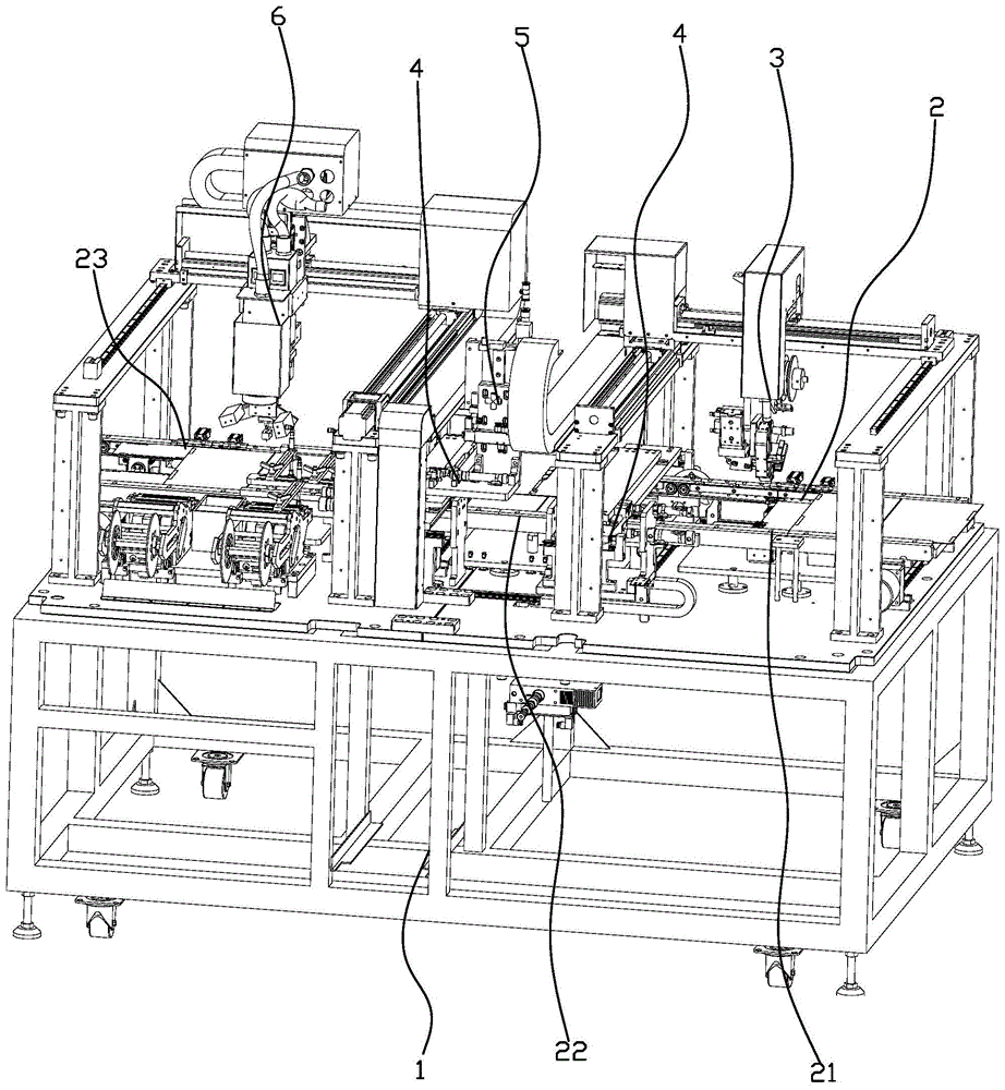
图1是本发明的装配示意图;Fig. 1 is the assembly schematic diagram of the present invention;
图2是本发明另一角度的装配示意图;Fig. 2 is the assembly schematic diagram of another angle of the present invention;
图3是本发明第三角度的装配示意图;Fig. 3 is the assembly diagram of the third angle of the present invention;
图4是本发明第四角度的装配示意图;Fig. 4 is the assembly diagram of the fourth angle of the present invention;
图5是本发明中高温胶贴装机构装配示意图;Fig. 5 is a schematic diagram of the assembly of the high-temperature glue mounting mechanism in the present invention;
图6是本发明中高温胶贴装机构另一角度的装配示意图;Fig. 6 is an assembly schematic diagram of another angle of the high-temperature glue mounting mechanism in the present invention;
图7是本发明中磁力座支撑组件的结构示意图;Fig. 7 is a schematic structural view of the magnetic base support assembly in the present invention;
图8是本发明中高温胶包裹机构的装配示意图;Fig. 8 is a schematic diagram of the assembly of the high-temperature glue wrapping mechanism in the present invention;
图9是本发明中高温胶包裹机构另一角度的装配示意图。Fig. 9 is an assembly schematic diagram of another angle of the high-temperature glue wrapping mechanism in the present invention.
具体实施方式Detailed ways
以下将结合实施例和附图对本发明的构思、具体结构及产生的技术效果进行清楚、完整地描述,以充分地理解本发明的目的、特征和效果。显然,所描述的实施例只是本发明的一部分实施例,而不是全部实施例,基于本发明的实施例,本领域的技术人员在不付出创造性劳动的前提下所获得的其他实施例,均属于本发明保护的范围。另外,专利中涉及到的所有联接/连接关系,并非单指构件直接相接,而是指可根据具体实施情况,通过添加或减少联接辅件,来组成更优的联接结构。本发明创造中的各个技术特征,在不互相矛盾冲突的前提下可以交互组合,参照图1-9。The idea, specific structure and technical effects of the present invention will be clearly and completely described below in conjunction with the embodiments and accompanying drawings, so as to fully understand the purpose, features and effects of the present invention. Apparently, the described embodiments are only some of the embodiments of the present invention, rather than all of them. Based on the embodiments of the present invention, other embodiments obtained by those skilled in the art without creative efforts belong to The protection scope of the present invention. In addition, all the connection/connection relationships involved in the patent do not simply refer to the direct connection of components, but mean that a better connection structure can be formed by adding or reducing connection accessories according to specific implementation conditions. Each technical feature in the present invention can be combined interactively on the premise of not contradicting each other, refer to Fig. 1-9.
一种用于金手指贴装包裹高温胶及贴标签的全自动设备,包括设备安装架1及安装在所述设备安装架1上的皮带输送线2、高温胶贴装机构3、高温胶包裹机构4、旋转横移机构5及贴标机构6,所述皮带输送线2具有三条,分别为皮带输送线A21、皮带输送线B22及皮带输送线C23,设备开始工作后,被加工的PCB板首先置于第一条皮带输送线2上并到达高温胶贴装工位,所述高温胶贴装机构3对PCB板进行高温胶贴胶工作,贴装完高温胶的PCB板在第二条皮带输送线2中输送到高温胶包裹工位,所述高温胶包裹机构4对PCB板进行高温胶包裹工作,包裹完高温胶的PCB板被旋转横移机构5旋转90度并放置于第三条皮带输送线2上,第三条皮带输送线2将PCB板送到贴标工位,所述贴标机构6对PCB板进行贴标。A fully automatic equipment for gold finger placement, wrapping, high-temperature glue and labeling, including an
优选地,所述高温胶贴装机构3包括贴胶顶升装置31及贴胶装置32,所述贴胶顶升装置31上设置有磁力座支撑组件33,所述贴胶装置32包括贴胶两轴移动组件321及安装在所述贴胶两轴移动组件321上的贴胶安装板322、高温胶供料装置323,所述贴胶安装板322上安装有贴胶驱动气缸324、贴胶头325、压胶驱动气缸326、压胶头327及高温胶剪切组件328,所述贴胶驱动气缸324可驱动贴胶头325抵靠到金手指上并贴高温胶,所述压胶驱动气缸326可驱动压胶头327压到金手指上的高温胶上并实现二次压紧,所述高温胶剪切组件328可将贴装完成的高温胶剪切断。Preferably, the high-temperature
优选地,所述磁力座支撑组件33包括磁力座331及设置在所述磁力座331上的齿形支撑座332,所述齿形支撑座332上配合设置有与其匹配的金手指支撑板333。Preferably, the magnetic
优选地,所述高温胶剪切组件328包括剪切驱动气缸及设置在所述剪切驱动气缸输出端的剪切刀片,所述剪切驱动气缸可驱动剪切刀片将高温胶剪切断;所述贴胶头325铰接在所述贴胶安装板322上,所述贴胶驱动气缸324的一端铰接在贴胶安装板322上,贴胶驱动气缸324的输出端铰接在贴胶头325的自由端并可驱动贴胶头325绕着其铰接点转动。Preferably, the high-temperature
优选地,所述贴胶顶升装置31包括贴胶顶升气缸311及安装在所述贴胶顶升气缸311输出端的贴胶顶升板312,所述贴胶顶升板312的四个边角处连接有贴胶顶升导柱313;所述贴胶两轴移动组件321包括贴胶X轴驱动组件及贴胶Y轴组件,所述X轴驱动组件及贴胶Y轴组件可分别驱动贴胶安装板322在X轴方向及Y轴方向移动。Preferably, the
在具体实施本发明时,通过所述贴胶顶升气缸311将贴胶顶升板312向上顶升起来,安装在贴胶顶升板312上的磁力座支撑组件33上升并抵靠在PCB板上的金手指下方;进一步所述两轴移动组件321配合运动,将贴胶头325的位置移动到金手指的起贴地点的上方,贴胶头325在贴胶驱动气缸324的驱动作用下向下移动并将高温胶贴在金手指前端的上表面;两轴移动组件321的Y轴组件匀速驱动贴胶头325运动,贴胶头325在摩擦力的作用下沿金手指的上表面滚动,同时不断地将高温胶贴在金手指上;在这个过程中,所述压胶驱动气缸326驱动压胶头327压向金手指上表面的高温胶上进行二次压紧,使得高温胶贴得更加稳固及平整,贴胶质量更好。当高温胶被贴到终点后,所述贴胶驱动气缸324驱动贴胶头325松开金手指,同时Y轴组件向后回退一小段距离,然后高温胶剪切组件328的剪切驱动气缸驱动剪切刀片将高温胶切断;高温胶被切断后,Y轴组件继续运动,直至切断的高温胶完全被压胶头327全部压紧在金手指上。至此,一次贴胶过程完成,机构复位。不断重复上述过程,就可以实现自动化贴胶,工作效率高,贴胶质量好。When implementing the present invention, the
在上述贴胶过程中,贴胶的起点和终点可以通过工作人员预设值进行操作,进而可根据不同种类的金手指设定不同的起点及终点,通用性强。In the above-mentioned gluing process, the starting point and end point of gluing can be operated through the preset values of the staff, and then different starting points and ending points can be set according to different types of golden fingers, which has strong versatility.
优选地,所述高温胶包裹机构4包括包裹顶升组件41及高温胶包裹组件42,所述包裹顶升组件41上设置有包裹磁力支撑组件44,所述高温胶包裹组件42包括左安装架421及右安装架422,所述左安装架421上设置有左斜角导向板423、左包裹气缸424及左包裹支撑气缸425,所述左斜角导向板423上设置有左包裹支撑板426,所述左包裹气缸424及左包裹支撑气缸425可分别推动左斜角导向板423及左包裹支撑板426滑动,所述右安装架422上设置有右斜角导向板427、右包裹气缸428及右包裹支撑气缸429,所述右斜角导向板427上设置有右包裹支撑板430,所述右包裹气缸428及右包裹支撑气缸429可分别推动右斜角导向板427及右包裹支撑板430滑动,所述左斜角导向板423及右斜角导向板427上均设置有包裹橡胶块431。Preferably, the high-temperature
优选地,所左安装架421上设置有第一左导轨,所述左斜角导向板423设置在所述第一左导轨上,所述左包裹气缸424的输出端连接到左斜角导向板423上并可推动左斜角导向板423在第一左导轨上滑动,所述左斜角导向板423上设置有第二左导轨,所述左包裹支撑板426设置在所述第二左导轨上,所述左包裹支撑气缸425的输出端连接到左包裹支撑板426上并可推动左包裹支撑板426在第二左导轨上滑动;所右安装架422上设置有第一右导轨,所述右斜角导向板427设置在所述第一右导轨上,所述右包裹气缸428的输出端连接到右斜角导向板427上并可推动右斜角导向板427在第一右导轨上滑动,所述右斜角导向板427上设置有第二右导轨,所述右包裹支撑板430设置在所述第二右导轨上,所述右包裹支撑气缸429的输出端连接到右包裹支撑板430上并可推动右包裹支撑板430在第二右导轨上滑动。Preferably, the left mounting frame 421 is provided with a first left guide rail, the left oblique guide plate 423 is arranged on the first left guide rail, and the output end of the left wrapped cylinder 424 is connected to the left oblique guide plate 423 and can push the left bevel guide plate 423 to slide on the first left guide rail, the left bevel guide plate 423 is provided with the second left guide rail, and the left package support plate 426 is arranged on the second left guide rail Above, the output end of the left package support cylinder 425 is connected to the left package support plate 426 and can push the left package support plate 426 to slide on the second left guide rail; the right mounting frame 422 is provided with the first right guide rail, so The right bevel guide plate 427 is arranged on the first right guide rail, the output end of the right package cylinder 428 is connected to the right bevel guide plate 427 and can push the right bevel guide plate 427 on the first right guide rail sliding, the right oblique guide plate 427 is provided with a second right guide rail, the right package support plate 430 is arranged on the second right guide rail, and the output end of the right package support cylinder 429 is connected to the right package support plate 430 and can push the right package support plate 430 to slide on the second right guide rail.
优选地,所述包裹橡胶块431为D形橡胶块;所述左安装架421底部设置有左安装架支撑板420,所述左安装架支撑板420通过左支撑导轨432安装在设备的固定安装件上。Preferably, the wrapped
所述包裹磁力支撑组件44包括包裹磁力支撑座441及设置在所述包裹磁力支撑座441上的包裹吸盘442;所述包裹顶升组件41包括包裹顶升驱动直线电机及包裹顶升板,所述包裹磁力支撑组件44设置在所述包裹顶升板上。The package
实施本发明时,首先,包裹顶升组件41在其包裹顶升驱动直线电机的驱动作用下推动包裹顶升板上升,设置在包裹顶升板上的包裹磁力支撑座组件44上升;当包裹磁力支撑座组件44上的包裹吸盘442将PCB板背面的高度时,包裹顶升组件41停止工作,所述包裹吸盘442的真空源开始工作并将PCB板吸住;进一步,包裹顶升组件41继续工作并将PCB板顶升,当PCB板通过所述左斜角导向板423及右斜角导向板427时,PCB板边沿伸出的高温胶会被左斜角导向板423及右斜角导向板427向下弯折90度;再进一步,所述包裹顶升组件41继续工作,PCB板继续上升,直到PCB板的上表面抵靠到左包裹支撑板426及右包裹支撑板430的下表面后,包裹顶升组件41停止工作,这时候,所述左包裹气缸424及右包裹气缸428分别驱动左斜角导向板423及右斜角导向板427相向运动,带动左斜角导向板423及右斜角导向板427上的包裹橡胶块431相向运动,所述包裹橡胶块431将已经弯折490度的高温胶包裹到PCB板的下表面。高温胶被包裹后,所述左包裹气缸424及右包裹气缸428分别驱动左斜角导向板423及右斜角导向板427向后运动,所述左包裹支撑气缸425及右包裹支撑气缸429分别驱动左包裹支撑板426及右包裹支撑板430向后运动,所述包裹顶升组件41继续工作并将完成高温胶包裹工作的PCB板顶升到预设位置(等待旋转横移机构5将PCB板取走)。When implementing the present invention, at first, the
至此,一块PCB板的高温胶自动包裹工作完成,实现自动化工作,效率高,质量稳定可靠。So far, the automatic wrapping of a PCB board with high-temperature glue is completed, realizing automatic work with high efficiency and stable and reliable quality.
优选地,旋转横移机构5包括旋转装置,所述贴标机构6包括自动送标装置、吸标装置、视觉对位装置、贴装标签装置及扫码装置。Preferably, the rotating and
以上是对本发明的较佳实施进行了具体说明,但本发明创造并不限于所述实施例,熟悉本领域的技术人员在不违背本发明精神的前提下还可做出种种的等同变形或替换,这些等同的变形或替换均包含在本申请权利要求所限定的范围内。The above is a specific description of the preferred implementation of the present invention, but the invention is not limited to the described embodiments, those skilled in the art can also make various equivalent deformations or replacements without violating the spirit of the present invention , these equivalent modifications or replacements are all within the scope defined by the claims of the present application.
Claims (6)
Priority Applications (1)
| Application Number | Priority Date | Filing Date | Title |
|---|---|---|---|
| CN201710465379.7A CN107128532B (en) | 2017-06-19 | 2017-06-19 | A fully automatic equipment for gold finger placement, wrapping, high temperature glue and labeling |
Applications Claiming Priority (1)
| Application Number | Priority Date | Filing Date | Title |
|---|---|---|---|
| CN201710465379.7A CN107128532B (en) | 2017-06-19 | 2017-06-19 | A fully automatic equipment for gold finger placement, wrapping, high temperature glue and labeling |
Publications (2)
| Publication Number | Publication Date |
|---|---|
| CN107128532A CN107128532A (en) | 2017-09-05 |
| CN107128532B true CN107128532B (en) | 2023-05-26 |
Family
ID=59735539
Family Applications (1)
| Application Number | Title | Priority Date | Filing Date |
|---|---|---|---|
| CN201710465379.7A Active CN107128532B (en) | 2017-06-19 | 2017-06-19 | A fully automatic equipment for gold finger placement, wrapping, high temperature glue and labeling |
Country Status (1)
| Country | Link |
|---|---|
| CN (1) | CN107128532B (en) |
Families Citing this family (3)
| Publication number | Priority date | Publication date | Assignee | Title |
|---|---|---|---|---|
| CN110589150A (en) * | 2019-09-09 | 2019-12-20 | 珠海冠宇电源有限公司 | Fully automatic PET and easy-to-pull glue all-in-one machine |
| CN112216769B (en) * | 2020-09-23 | 2025-01-28 | 苏州晟成光伏设备有限公司 | A photovoltaic module lead bending and barcode pasting machine |
| CN117383027B (en) * | 2023-12-11 | 2024-02-20 | 荣旗工业科技(苏州)股份有限公司 | Surface attaching equipment and attaching method |
Family Cites Families (6)
| Publication number | Priority date | Publication date | Assignee | Title |
|---|---|---|---|---|
| CN101457128A (en) * | 2007-12-14 | 2009-06-17 | 3M创新有限公司 | Composite high temperature gummed tape and method for producing the same |
| CN103956522B (en) * | 2014-05-14 | 2016-02-03 | 山东爱通工业机器人科技有限公司 | A kind of lithium battery sheet group left and right sides tape sticking device |
| CN205069782U (en) * | 2015-08-13 | 2016-03-02 | 深圳市东博自动化设备有限公司 | Multi -functional side of lithium cell rubberizing machine |
| CN105609880A (en) * | 2015-12-18 | 2016-05-25 | 深圳吉阳智云科技有限公司 | Battery core encapsulating machine |
| CN106602127B (en) * | 2017-01-10 | 2019-07-05 | 深圳市欧盛自动化有限公司 | Full-automatic patch head high tempreture tape machine |
| CN207191530U (en) * | 2017-06-19 | 2018-04-06 | 深圳市宝尔威精密机械有限公司 | A kind of fully-automatic equipment that high-temp glue and labelling are wrapped up for golden finger attachment |
-
2017
- 2017-06-19 CN CN201710465379.7A patent/CN107128532B/en active Active
Also Published As
| Publication number | Publication date |
|---|---|
| CN107128532A (en) | 2017-09-05 |
Similar Documents
| Publication | Publication Date | Title |
|---|---|---|
| CN110884938A (en) | Adhesive tape cutting and sticking equipment | |
| WO2021120907A1 (en) | Automatic adhesive coating mechanism for pcbs | |
| CN219132648U (en) | Edge sealing mechanism for furniture plate | |
| CN209274161U (en) | A kind of code-spraying equipment | |
| CN110696430A (en) | A kind of production process of heaven and earth cover packaging box | |
| CN107128532A (en) | A kind of fully-automatic equipment that parcel high-temp glue and labelling are mounted for golden finger | |
| CN113860053A (en) | Automatic paste beautiful line of battery and glue equipment | |
| CN105729885B (en) | A kind of carton forming equipment | |
| CN207191530U (en) | A kind of fully-automatic equipment that high-temp glue and labelling are wrapped up for golden finger attachment | |
| CN216400689U (en) | An automatic packaging production line | |
| CN108033067A (en) | A kind of carton forming packing machine and its packing method | |
| CN115763935A (en) | A battery hot-pressing encapsulation device | |
| CN105729886B (en) | A kind of automatic bonding mechanism of lid and box body | |
| CN211310366U (en) | Adhesive tape cutting and sticking equipment | |
| CN110733682B (en) | Bulb shell packaging device | |
| CN209740364U (en) | Automatic tape pasting mechanism with high tape pasting efficiency | |
| CN209615829U (en) | A kind of full automatic edge bander | |
| CN205573131U (en) | Carton former | |
| CN217512594U (en) | Bending device is used in processing of aviation metal product | |
| CN109823645B (en) | Automatic paste sponge equipment | |
| CN213134396U (en) | Glass sheet belt cleaning device | |
| CN216659070U (en) | Intelligent integrated online assembling device | |
| CN211994385U (en) | Punching and L-shaped hook mounting integrated equipment for top and bottom cover box | |
| CN214931341U (en) | Automatic labeling equipment for carton | |
| CN215044454U (en) | Quick mark device that pastes of cosmetic packaging bottle lid |
Legal Events
| Date | Code | Title | Description |
|---|---|---|---|
| PB01 | Publication | ||
| PB01 | Publication | ||
| SE01 | Entry into force of request for substantive examination | ||
| SE01 | Entry into force of request for substantive examination | ||
| GR01 | Patent grant | ||
| GR01 | Patent grant | ||
| PE01 | Entry into force of the registration of the contract for pledge of patent right | ||
| PE01 | Entry into force of the registration of the contract for pledge of patent right |
Denomination of invention: A fully automatic device for wrapping high-temperature adhesive and labeling with gold fingers Granted publication date: 20230526 Pledgee: Shenzhen Branch of Guangdong Huaxing Bank Co.,Ltd. Pledgor: SHENZHEN BORWIN PRECISION MACHINERY Co.,Ltd. Registration number: Y2024980004703 |
|
| PC01 | Cancellation of the registration of the contract for pledge of patent right | ||
| PC01 | Cancellation of the registration of the contract for pledge of patent right |
Granted publication date: 20230526 Pledgee: Shenzhen Branch of Guangdong Huaxing Bank Co.,Ltd. Pledgor: SHENZHEN BORWIN PRECISION MACHINERY Co.,Ltd. Registration number: Y2024980004703 |
|
| PE01 | Entry into force of the registration of the contract for pledge of patent right | ||
| PE01 | Entry into force of the registration of the contract for pledge of patent right |
Denomination of invention: A fully automatic device for attaching and wrapping high-temperature adhesive and labeling with gold fingers Granted publication date: 20230526 Pledgee: Shenzhen Branch of Guangdong Huaxing Bank Co.,Ltd. Pledgor: SHENZHEN BORWIN PRECISION MACHINERY Co.,Ltd. Registration number: Y2025980002239 |