CN107072486B - Coordinated positioning distal tip for an endoscope with suction device - Google Patents
Coordinated positioning distal tip for an endoscope with suction device Download PDFInfo
- Publication number
- CN107072486B CN107072486B CN201680002365.5A CN201680002365A CN107072486B CN 107072486 B CN107072486 B CN 107072486B CN 201680002365 A CN201680002365 A CN 201680002365A CN 107072486 B CN107072486 B CN 107072486B
- Authority
- CN
- China
- Prior art keywords
- tip
- aperture
- colon
- endoscope
- distal
- Prior art date
- Legal status (The legal status is an assumption and is not a legal conclusion. Google has not performed a legal analysis and makes no representation as to the accuracy of the status listed.)
- Active
Links
Images


Classifications
-
- A—HUMAN NECESSITIES
- A61—MEDICAL OR VETERINARY SCIENCE; HYGIENE
- A61B—DIAGNOSIS; SURGERY; IDENTIFICATION
- A61B1/00—Instruments for performing medical examinations of the interior of cavities or tubes of the body by visual or photographical inspection, e.g. endoscopes; Illuminating arrangements therefor
- A61B1/00064—Constructional details of the endoscope body
- A61B1/00071—Insertion part of the endoscope body
- A61B1/0008—Insertion part of the endoscope body characterised by distal tip features
- A61B1/00089—Hoods
-
- A—HUMAN NECESSITIES
- A61—MEDICAL OR VETERINARY SCIENCE; HYGIENE
- A61B—DIAGNOSIS; SURGERY; IDENTIFICATION
- A61B1/00—Instruments for performing medical examinations of the interior of cavities or tubes of the body by visual or photographical inspection, e.g. endoscopes; Illuminating arrangements therefor
- A61B1/00064—Constructional details of the endoscope body
- A61B1/00071—Insertion part of the endoscope body
- A61B1/0008—Insertion part of the endoscope body characterised by distal tip features
- A61B1/00094—Suction openings
-
- A—HUMAN NECESSITIES
- A61—MEDICAL OR VETERINARY SCIENCE; HYGIENE
- A61B—DIAGNOSIS; SURGERY; IDENTIFICATION
- A61B1/00—Instruments for performing medical examinations of the interior of cavities or tubes of the body by visual or photographical inspection, e.g. endoscopes; Illuminating arrangements therefor
- A61B1/00064—Constructional details of the endoscope body
- A61B1/00071—Insertion part of the endoscope body
- A61B1/0008—Insertion part of the endoscope body characterised by distal tip features
- A61B1/00101—Insertion part of the endoscope body characterised by distal tip features the distal tip features being detachable
-
- A—HUMAN NECESSITIES
- A61—MEDICAL OR VETERINARY SCIENCE; HYGIENE
- A61B—DIAGNOSIS; SURGERY; IDENTIFICATION
- A61B1/00—Instruments for performing medical examinations of the interior of cavities or tubes of the body by visual or photographical inspection, e.g. endoscopes; Illuminating arrangements therefor
- A61B1/00112—Connection or coupling means
- A61B1/00121—Connectors, fasteners and adapters, e.g. on the endoscope handle
- A61B1/00128—Connectors, fasteners and adapters, e.g. on the endoscope handle mechanical, e.g. for tubes or pipes
-
- A—HUMAN NECESSITIES
- A61—MEDICAL OR VETERINARY SCIENCE; HYGIENE
- A61B—DIAGNOSIS; SURGERY; IDENTIFICATION
- A61B1/00—Instruments for performing medical examinations of the interior of cavities or tubes of the body by visual or photographical inspection, e.g. endoscopes; Illuminating arrangements therefor
- A61B1/00131—Accessories for endoscopes
- A61B1/0014—Fastening element for attaching accessories to the outside of an endoscope, e.g. clips, clamps or bands
-
- A—HUMAN NECESSITIES
- A61—MEDICAL OR VETERINARY SCIENCE; HYGIENE
- A61B—DIAGNOSIS; SURGERY; IDENTIFICATION
- A61B1/00—Instruments for performing medical examinations of the interior of cavities or tubes of the body by visual or photographical inspection, e.g. endoscopes; Illuminating arrangements therefor
- A61B1/012—Instruments for performing medical examinations of the interior of cavities or tubes of the body by visual or photographical inspection, e.g. endoscopes; Illuminating arrangements therefor characterised by internal passages or accessories therefor
- A61B1/015—Control of fluid supply or evacuation
-
- A—HUMAN NECESSITIES
- A61—MEDICAL OR VETERINARY SCIENCE; HYGIENE
- A61B—DIAGNOSIS; SURGERY; IDENTIFICATION
- A61B1/00—Instruments for performing medical examinations of the interior of cavities or tubes of the body by visual or photographical inspection, e.g. endoscopes; Illuminating arrangements therefor
- A61B1/31—Instruments for performing medical examinations of the interior of cavities or tubes of the body by visual or photographical inspection, e.g. endoscopes; Illuminating arrangements therefor for the rectum, e.g. proctoscopes, sigmoidoscopes, colonoscopes
Abstract
Devices for engaging an endoscope with a system for cleaning the colon or other body cavity are disclosed. Embodiments include variable placement of the distal portion of the suction component relative to the endoscope, the plurality of suction tubes and/or suction inlets, and a means for protecting the colon wall from suction damage.
Description
RELATED APPLICATIONS
This application claims priority from U.S. patent application No. 14/722,400 filed on day 27 of 5/2015 according to 35 (e) of the U.S. code, which is part of the continuation-in-part application (CIP) of PCT patent application No. PCT/IL2014/051014 filed on day 20 of 11/2014, and claims priority from U.S. code 35 (e) of the U.S. code, which claims priority from U.S. provisional patent application No. 62/012,997 filed on day 17 of 6/2014 and 61/906,982 filed on day 21 of 11/2013. The contents of the above applications are incorporated by reference in their entirety as if fully set forth herein.
Technical field and background
In some embodiments thereof, the present invention relates to a tool for use with an endoscope, and more particularly, but not exclusively, to components for insertion with an endoscope into a body cavity and for cleaning the body cavity to facilitate visualization of the lumen by means of the endoscope. For example, some embodiments may be used with a colonoscope to clean the colon during colonoscopy.
During colonoscopy, fecal matter is removed from the colon using tubes dedicated to the flushing and draining tasks. Typically, the colonoscope wash channel carries fluid for loosening, dissolving and/or breaking up fecal material into the colon; and the working channel discharges the material.
Automated cleaning systems have been described that add irrigation and/or drainage channels to the colonoscope probe; for example, in international patent publication No. WO2009/143201 filed on 5/20 th 2009 and WO2010/138521 filed on 12/2 th 2010.
Disclosure of Invention
According to an aspect of some embodiments of the present invention there is provided a tip adaptor for a colon cleaning system for use with a colonoscope probe, the tip adaptor comprising a housing having a hollow region sized to fittingly receive an insert, the insert comprising a plurality of sockets, each fittingly receiving a distal end of one or more respective fluid transfer tubes, wherein one of the insert and the housing comprises a resiliently deformable material and the other comprises a relatively rigid material.
According to some embodiments of the invention, the shell is comprised of a softer material than the insert, and the shell is deformable around the insert in response to an external force while the insert remains in place and is substantially undeformed.
According to some embodiments of the invention, the bladder defines at least one elastically collapsible hollow.
According to some embodiments of the invention, the collapsible hollow comprises a guard wall extending across the aperture of at least one of the sockets and spaced from the aperture along the longitudinal axis of the socket.
According to some embodiments of the invention, the guard wall comprises an aperture of the collapsible hollow.
According to some embodiments of the invention, the aperture of the socket is a suction intake aperture.
According to some embodiments of the invention, the apertures of the retaining wall have substantially the same size and shape as the suction intake apertures.
According to some embodiments of the invention, the guard wall is spaced from the aperture along the longitudinal axis of the socket by at least 5 mm.
According to some embodiments of the invention, the collapsible hollow is sufficiently flexible to elastically collapse when pressed from within against a portion of the colon wall, the collapse occurring at a force less than the force damaging the portion of the colon wall.
According to some embodiments of the invention, the housing comprises an aperture surrounding the aperture of at least one of the sockets.
According to some embodiments of the invention, the orifice of the socket is an irrigation orifice.
According to some embodiments of the invention, the flushing orifice is shaped to form the fluid into a jet when the fluid is supplied through the flushing orifice, and the orifice of the housing is large enough to avoid interference with the jet.
According to some embodiments of the invention, the shell is constructed of a harder material than the insert, and the insert is deformable between the receptacles.
According to some embodiments of the invention, the soft insert is sufficiently flexible to deform as the fluid transport tube moves while maintaining mating contact with the fluid transport tube and the hollow region.
According to some embodiments of the invention, the shape of the harder shell is maintained during deformation.
According to some embodiments of the invention, the tip adaptor comprises a socket sized to receive a distal portion of a colonoscope probe.
According to some embodiments of the invention, the tip adaptor is attached to a distal end of an evacuation channel sized for insertion into a distal segment of the colon.
According to some embodiments of the invention, the adaptor is attached such that it is positioned to aspirate waste from the distal segment of the colon to the evacuation channel when inserted therein.
According to some embodiments of the invention, the tip adaptor comprises a colon barrier integrally formed with the shell, attached to a circumference of the tip adaptor and extending radially therefrom; the colon barrier is sufficiently flexible that it collapses upon receiving pressure as the tip adaptor is moved forward into the radially restricted colon region.
According to an aspect of some embodiments of the present invention there is provided a method of navigating a tip adapter at a distal end of a colon cleaning device, comprising: advancing the tip adapter to press against a portion of the soft tissue; and collapsing a portion of the tip adapter against the soft tissue, thereby reducing a maximum pressure of the tip adapter against the soft tissue.
According to some embodiments of the invention, the tip adaptor comprises a plurality of sockets attached to a corresponding plurality of lumens of the colon cleaning device; and the socket remains undeformed while the portion of the tip adaptor collapses.
According to an aspect of some embodiments of the present invention there is provided a cleaning system for evacuating waste from a lumen of a tubular alimentary tract, comprising: at least one evacuation lumen having a distal end configured for insertion into the distal section of the alimentary tract lumen; the at least one discharge lumen is configured to deliver suction to the distal end; a guard wall defining a suction inlet at a distal end, the suction inlet being distal to the proximal tissue of the alimentary tract lumen when inserted therein.
According to some embodiments of the invention, the guard wall extends distally from an air intake cross-section of the evacuation lumen, the evacuation lumen comprising a distal-most region having substantially the same cross-section as a main proximal region of the evacuation lumen.
According to some embodiments of the invention, a portion of the distal extension of the retaining wall extends medially with respect to a central axis perpendicular to the air intake cross-section.
According to some embodiments of the invention, the area of the suction inlet defined by the retaining wall is at least 2 times greater than the area of the intake cross-section.
According to some embodiments of the invention, the guard wall extends circumferentially around at least a portion of a cross-section of the distal portion of the colonoscope probe when the adaptor is attached to the distal portion.
According to some embodiments of the invention, the retaining wall extends completely around the cross-section.
According to an aspect of some embodiments of the invention (including, for example, any of the embodiments described herein), there is provided a cleaning system for evacuating waste from a lumen of a tubular digestive tract, comprising: at least one evacuation lumen having a distal access aperture configured for insertion into a distal segment of an alimentary tract lumen; the at least one exhaust cavity is configured to impart suction to the inlet aperture; a retaining wall that separates the air intake orifice from the proximal tissue of the alimentary tract lumen when inserted therein; the retaining wall defines a suction inlet positioned to divert suction away from proximate tissue.
According to some embodiments of the invention, including, for example, any of the embodiments described herein, the guard wall extends distally from the air intake aperture.
According to some embodiments of the invention, including, for example, any of the embodiments described herein, a portion of the distal extension of the guard wall extends medially with respect to a central axis perpendicular to the air intake aperture.
According to some embodiments of the invention, including, for example, any of the embodiments described herein, a portion of the retaining wall continues from the medially extending portion beyond the central axis.
According to some embodiments of the invention, including for example any of the embodiments described herein, the area of the suction inlet defined by the retaining wall is at least 2 times greater than the area of the air intake aperture.
According to some embodiments of the invention, including, for example, any of the embodiments described herein, the distal extension is at least 5 mm.
According to some embodiments of the invention, including, for example, any of the embodiments described herein, the system comprises an adapter attachable to a distal portion of a colonoscope probe, wherein the adapter comprises a retaining wall.
According to some embodiments of the invention, including, for example, any of the embodiments described herein, the guard wall extends circumferentially from a portion of the air intake aperture around at least a portion of a cross-section of the distal portion of the colonoscope probe when the adaptor is attached to the distal portion.
According to some embodiments of the invention, including, for example, any of the embodiments described herein, the retaining wall extends completely around the cross-section.
According to some embodiments of the invention, including, for example, any of the embodiments described herein, the guard wall tapers in a distal direction.
According to some embodiments of the invention, the taper distally ends with a blunt face.
According to some embodiments of the invention, including, for example, any of the embodiments described herein, the guard wall comprises a tapered portion that extends into a region defined by a vertical projection of a distal circumference of a distal portion of the colonoscope probe distally therefrom when the adaptor and the colonoscope probe are attached.
According to some embodiments of the invention, including, for example, any of the embodiments described herein, the tapered portion extends around its entire circumference into the region defined by the protrusion.
According to some embodiments of the invention, including, for example, any of the embodiments described herein, the diverting comprises deviating the suction inlet at least 30 degrees from a direction parallel or perpendicular to a distal-proximal axis of the distal portion of the discharge lumen.
According to some embodiments of the invention, including, for example, any of the embodiments described herein, the distal extension is at least 20% around a circumference surrounding the air intake aperture, extends distally at least 5mm from the air intake aperture, and comprises a wall at least 0.1mm thick.
According to some embodiments of the invention, including, for example, any of the embodiments described herein, the guard wall extends distally to a limit defined by exclusion from a field of view of an imaging device included in the colonoscope probe.
According to some embodiments of the invention, including, for example, any of the embodiments described herein, the guard wall comprises at least one vent hole positioned to allow fluid to pass therethrough to a side facing the air intake aperture when receiving suction.
According to some embodiments of the invention, including for example any of the embodiments described herein, the at least one vent hole comprises an open area that is less than 50% of the area of the suction inlet.
According to some embodiments of the invention, including, for example, any of the embodiments described herein, the pressure differential across the at least one vent hole is less than half of a maximum pressure differential associated with the suction force.
According to some embodiments of the invention, the at least one vent hole is axially aligned with the suction inlet and is spaced therefrom by a chamber having an axial cross-section at least as large as the suction inlet.
According to some embodiments of the invention, the chamber further comprises a pressure relief aperture in fluid communication with the alimentary tract lumen through the at least one additional lumen, the pressure relief aperture positioned along a chamber wall extending between the at least one vent and the suction inlet.
According to some embodiments of the invention, including for example any of the embodiments described herein, the suction inlet comprises a mouth that is non-planar around its lip.
According to some embodiments of the invention, including for example any of the embodiments described herein, the suction inlet comprises a plurality of apertures positioned so as not to be simultaneously obstructed by a wall region extending around less than a quarter of the circumference, including a portion of the aperture.
According to some embodiments of the invention, including, for example, any of the embodiments described herein, the guard wall separates the air intake aperture of at least the second evacuation lumen from the nearest tissue.
According to some embodiments of the invention, including, for example, any of the embodiments described herein, the lumen of the alimentary tract is a colon.
According to some embodiments of the invention, including for example any of the embodiments described herein, the suction inlet is sufficiently large to prevent complete blockage by a protruding portion of the wall having a height of less than 5 mm.
According to some embodiments of the invention, including for example any of the embodiments described herein, the suction inlet is protected from at least one side so that it cannot be completely blocked by a continuous wall portion extending more than 10mm beyond the contact area.
According to an aspect of some embodiments of the invention, including for example any of the embodiments described herein, there is provided a cleaning system for use with a colonoscope probe, comprising: an adaptor attached to a distal end of an evacuation channel sized for insertion into a distal segment of a colon; an adapter may be attached to a distal portion of the colonoscope probe; the distal portion, when attached, approximates a portion of the colonoscope probe having an outer diameter greater than the inner diameter of the adapter.
According to some embodiments of the invention, including, for example, any of the embodiments described herein, the adaptor is attached such that it is positioned to aspirate waste from the distal segment of the colon to the evacuation channel when inserted therein.
According to an aspect of some embodiments of the invention, including for example any of the embodiments described herein, there is provided a cleaning system for use with a colonoscope probe, comprising: an adaptor attached to a distal end of an evacuation lumen, the evacuation lumen configured for insertion into a distal segment of a colon; the adapter includes a gap; the gap is capable of passing through a sidewall of the distal portion of the colonoscope probe and from a direction perpendicular to the sidewall for attaching the adaptor thereto.
According to some embodiments of the invention, including, for example, any of the embodiments described herein, the adapter is attached to the distal end of the irrigation channel.
According to some embodiments of the invention, including for example any of the embodiments described herein, the gap may widen to pass over the widest extent of the side wall, the widened gap narrowing again after the widest extent to form the attachment.
According to some embodiments of the invention, including, for example, any of the embodiments described herein, the gap may be widened by pulling apart portions of the adapter on either side of the gap.
According to some embodiments of the invention, including, for example, any of the embodiments described herein, the widening and narrowing of the gap comprises an elastic deformability of the adapter.
According to some embodiments of the invention, including, for example, any of the embodiments described herein, the adapter including the gap is sized to surround more than 180 degrees of the circumference of the sidewall.
According to some embodiments of the invention, including, for example, any of the embodiments described herein, the adapter including the gap is sized to surround more than 270 degrees of the circumference of the sidewall.
According to an aspect of some embodiments of the present invention there is provided a tip adaptor for a colon cleaning system for use with a colonoscope probe, comprising: an evacuation inlet region located on a distal surface of the tip adaptor and offset from a radial center of the surface, the evacuation inlet region comprising an aperture configured for connection to a suction source operable when the tip adaptor is inserted into the distal end of the colon while attached to a colonoscope probe; a colon barrier attached to the circumference of the tip adaptor on the side of the exit portal region offset and extending radially therefrom; the colon barrier is sufficiently flexible that it collapses upon receiving pressure as the tip adaptor is moved forward into the radially restricted colon region.
According to some embodiments of the invention, the colon barrier is directed to one side of the tip adaptor.
According to some embodiments of the invention, collapsing comprises bending proximally and substantially parallel to the body of the tip adapter during passage through the restriction.
According to an aspect of some embodiments of the present invention there is provided a method of navigating a colon cleaning device through a colon, comprising: orienting a colon partition extending radially from a distal tip adapter of a colon cleaning system while applying evacuation suction through a colon cleaning device to push the tip adapter away from a wall portion of a colon; and collapsing the colon barrier such that the tip adaptor is proximate the wall portion.
According to some embodiments of the invention, collapsing comprises translating the tip adaptor along the proximal-distal axis while a portion of the colon isolator is dragged over the colon, such that the flexible member collapses and the tip adaptor approaches the colon wall portion.
According to some embodiments of the invention, the method comprises re-extending the collapsed colon spacer by again translating the tip adaptor.
According to an aspect of some embodiments of the present invention there is provided a tip adaptor for a colon cleaning system for use with a colonoscope probe, the tip adaptor comprising a rigid shell having a hollow region sized to fittingly receive a soft insert, the soft insert comprising a plurality of deformable sockets, each fittingly receiving a distal end of one or more respective fluid transfer tubes.
According to some embodiments of the invention, the soft insert is sufficiently flexible to deform as the fluid transport tube moves while maintaining mating contact with the fluid transport tube and the hollow region.
According to some embodiments of the invention, the shape of the hard shell is maintained during deformation.
Unless defined otherwise, all technical and/or scientific terms used herein have the same meaning as commonly understood by one of ordinary skill in the art to which this invention belongs. Although methods and materials similar or equivalent to those described herein can be used in the practice or testing of embodiments of the present invention, exemplary methods and/or materials are described below. In case of conflict, the present specification, including definitions, will control. In addition, the materials, methods, and embodiments are illustrative only and not intended to be necessarily limiting.
Drawings
Some embodiments of the invention are described herein, by way of example only, with reference to the accompanying drawings. Referring now in detail to the drawings, it is stressed that the particulars shown are by way of example and for purposes of illustrative discussion of the embodiments of the present invention. In this regard, the description taken with the drawings make apparent to those skilled in the art how the embodiments of the invention may be embodied.
In the drawings:
1A-1B show simplified schematic diagrams of cleaning systems that may be used with an endoscope, according to some exemplary embodiments of the present invention;
2A-2C schematically illustrate a tip adapter including a shield according to some exemplary embodiments of the invention;
2D-2E illustrate an encounter between a portion of an intestinal wall and a vacuum drawn through an evacuation lumen of a tip adapter according to some exemplary embodiments of the present invention;
3A-3B illustrate an encounter between a portion of an intestinal wall and a vacuum drawn through an extended evacuation lumen of a tip adapter according to some exemplary embodiments of the present invention;
4A-4B schematically illustrate a tip adapter including a shield having at least one aperture according to some example embodiments of the invention;
5A-5B illustrate drainage of fluid and suspended waste from the intestinal lumen according to some exemplary embodiments of the present invention;
6A-6B illustrate a shield associated with an imaging aperture according to some exemplary embodiments of the present invention;
7A-7C schematically illustrate examples of tip adapters including full circumferential shielding according to some exemplary embodiments of the present invention;
8A-8C schematically illustrate examples of tip adapters including end-female shields according to some exemplary embodiments of the invention;
9A-9D illustrate attachment of an adapter tip to an endoscope distal end having a variable diameter according to some exemplary embodiments of the present invention;
10A-10D illustrate end-to-end attachment of an adapter tip to the distal end of an endoscope according to some exemplary embodiments of the present invention;
11A-11C schematically illustrate a configuration of a cleaning system tip adapter mountable on a distal portion of an endoscope, according to some exemplary embodiments of the present invention;
fig. 11D illustrates a tip adapter for end-to-end application associated with a distal portion of an endoscope, according to some exemplary embodiments of the present invention;
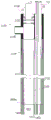
12A-12B illustrate front and side cross-sectional views, respectively, of a tip adapter associated with the distal end of an endoscope, according to some exemplary embodiments of the present invention;
13A-13C schematically illustrate a configuration of a cleaning system tip adapter mountable on a distal portion of an endoscope, according to some exemplary embodiments of the present invention;
14A-14C illustrate attachment of a tip adapter to an endoscopic probe including an expanded distal portion according to some exemplary embodiments of the present invention;
15A-15B schematically illustrate different circumferential extents of an elastically deformable tip adapter according to some exemplary embodiments of the present invention;
fig. 15C shows an extension of the housing region of the tip adapter on the distal flare according to some exemplary embodiments of the present invention;
16A-16C illustrate an elastically deformable tip adapter in three configurations relative to a distal portion of an endoscope, according to some exemplary embodiments of the present invention;
17A-17B schematically illustrate a configuration of a cleaning system tip adapter mountable on a distal portion of an endoscope, according to some exemplary embodiments of the present invention;
18A-18C schematically illustrate tip adapters including housings and inserts of different durometers according to some exemplary embodiments of the invention;
19A-19C schematically illustrate a tip adapter including a pre-evacuation chamber according to some exemplary embodiments of the invention;
fig. 20 schematically illustrates a tip adapter including a flexible retaining wall according to some exemplary embodiments of the invention;
fig. 21 schematically illustrates a sleeve assembly in a sleeve placement jig according to some exemplary embodiments of the invention and components of an irrigation system and a colonoscope;
fig. 22 shows the position of the distal region of the cleaning system (including, for example, the adapter tip) relative to the intestinal wall and the flexible retaining wall; and is
Fig. 23 schematically illustrates particles entering a distal tip adapter according to some exemplary embodiments of the invention.
Detailed Description
In some embodiments thereof, the present invention relates to a tool for use with an endoscope, and more particularly, but not exclusively, to components for insertion with an endoscope into a body cavity and for cleaning the body cavity to facilitate visualization of the lumen by means of the endoscope. For example, some embodiments may be used with a colonoscope to clean the colon during colonoscopy.
Overview
A broad aspect of some embodiments of the invention relates to a tip adaptor for connecting a distal portion of an endoscope with a distal portion of a cleaning module for cleaning a colon or other body cavity.
In some embodiments of the invention, the probe of the lumen cleaning module (cleaning system) is sized for reaching the end of the colon or another portion of the gastrointestinal tract. In some embodiments, the lumen cleaning module is adapted to pump a flushing fluid to the distal end of the probe to remove, disaggregate, dissolve and/or suspend fecal matter in the colon. In some embodiments, the lumen cleaning module is adapted to drain loose fecal matter from the colon through the lumen of the probe.
An aspect of some embodiments of the invention relates to a dual durometer or multi-durometer construction of the tip adapter, e.g., such that the outer portion of the tip adapter is relatively rigid and the insert to the outer portion is relatively soft, and/or such as such that the outer portion of the tip adapter is relatively soft and the insert to the outer portion is relatively hard.
In some embodiments of the invention, a soft insert and a hard outer portion are provided.
In some embodiments of the invention, the soft insert includes a socket sized to receive a connection to a fluid transfer tube, such as an exhaust channel, irrigation fluid supply conduit, and/or pressure sensing tube. In some embodiments, the soft insert serves to absorb and/or dampen movement of the fluid transfer tube such that displacements due to movement of the tube relative to the tip are distributed in the body of the soft insert rather than being concentrated in the interface region between the fluid transfer tube and its respective socket. In some embodiments, the hard portion of the tip adaptor is sufficiently hard to resist deformation due to direct external forces that may be encountered during colon navigation. Potentially, this helps shield the jack connection from deformation that may tend to loosen the connection. Potentially, the relatively inflexible construction of the hard portion of the tip adaptor resists deformation which may tend to allow the tip to be struck rather than slipping over a protrusion in the intestinal wall.
In some embodiments, the deformable property of the soft insert comprises a movement of about 0.1mm in response to a force of between 1-10 newtons. In some embodiments, the movement corresponds to a range of movement of about 0.1-0.25mm, 0.15-0.2mm, 0.25-0.5mm, or with the same, larger, smaller, and/or intermediate limits.
In some embodiments of the invention, a hard insert and a soft outer portion are provided.
Optionally, the hard insert includes a socket sized to receive a connection with a fluid delivery tube, such as a drain channel, irrigation fluid supply conduit, and/or pressure sensing tube. Optionally, the use of a relatively hard insert connected to the soft outer portion allows for tight tolerances in manufacturing the socket for receiving the fluid transfer tube and/or the pressure sensing tube, while still allowing for the soft outer portion, thereby mitigating potential traumatic interaction between the device head and surrounding tissue during operation.
Potentially, the use of relatively hard inserts provides dimensional stability during storage and/or use. For example, the stability of the connection of the socket to the pipe is maintained by the hard insert substantially resisting deformation under the forces of use and/or resisting forces or creep due to storage. Optionally, the relatively hard insert provides dimensional stability of the orifice, e.g., an orifice shaped to form and/or direct a jet of fluid for cleaning. Without the dimensional stability of the ejection orifice, the ejection force, shape and/or direction may change during storage and/or use.
In some embodiments, the bladder of the tip adapter reduces the likelihood of tissue damage due to interaction with the tip adapter. For example, the surface of the tip adapter itself has some rubber-like properties to allow distribution of the force, potentially preventing the force from concentrating on small areas of soft tissue. In some embodiments, one or more portions of the tip adapter bladder are configured to partially and elastically collapse upon receiving a force, thereby further providing a tip adapter shape.
In some embodiments, the orifice (e.g., jet and/or orifice) defined by the hard insert portion and formed to be dimensionally stable is protected by a surrounding portion of the bladder. For example, the bladder has a hole wide enough to avoid interfering with the function (e.g., shape and/or aiming) of the ejection orifice and surrounds the ejection orifice to prevent direct tissue interaction therewith. Optionally, the soft shell aperture is disposed spaced apart from and in front of the suction aperture defined by the hard insert, thereby potentially protecting tissue from the hard edges of the suction aperture.
In some embodiments, the deformable properties of the soft shell (e.g., the shell that directly covers the hard insert portion) include a movement of about 0.1mm in response to a force of between 1-10 newtons. In some embodiments, the movement corresponds to a range of movement of about 0.1-0.25mm, 0.15-0.2mm, 0.25-0.5mm, or with the same, larger, smaller, and/or intermediate limits. In some embodiments, the bladder includes one or more collapsible chambers and/or hollows and is configured to allow elastic collapse to a degree (e.g., 1mm, 2mm, 3mm, 4mm, 5mm, or another greater or lesser range) determined at least in part by the size of the chamber or hollow, e.g., in response to a force between 1-10 newtons. The hollow likewise has a length in the direction of collapse of, for example, about 1mm, 2mm, 3mm, 4mm, 5mm or another greater or lesser distance. Or, for example, in embodiments where the chamber is sealed, collapse to an intermediate extent governed by the compressibility of the chamber wall and/or contents.
It should be understood that the extent and/or abutment of the relatively hard and relatively soft portions of the tip adapter optionally undergo further variations and combinations. Optionally, for example, the shell includes a hard portion and a soft portion. For example, the corners, leading surfaces, and/or other surfaces of the shell are formed as soft, yielding, and/or compressible portions of the shell, while other portions of the shell (exposed as surfaces and/or supporting the compressible portions from within) are formed as relatively hard portions of the shell. Additionally or alternatively, the insertion portion is formed of a hard, rigid and/or incompressible portion that provides dimensional stability of the components, such as the socket shape and irrigation inlet shape, and e.g. a soft lining of the socket (potentially allowing slight deformation upon application of force, but thin enough that functionally important dimensional stability provided by the hard portion is not affected). Additionally or alternatively, the hard socket and/or irrigation inlet is embedded within a matrix of softer material. Potentially, this allows some given and/or relative movement of the socket to absorb forces exerted on the tip while maintaining the required dimensional stability, e.g., to securely hold the fitting and/or reliably form the jet. Thus, the tip adapter is optionally provided with multiple layers of alternating hardness and softness within the housing and/or within the insert, potentially allowing at least some of the advantages of each material type to be provided.
Further, while embodiments herein are described with respect to "housings" and "inserts" that are optionally separable, it should be understood that the two elements are optionally manufactured as a single unit. Alternatively, any of the elements are optionally manufactured as multiple pieces, which are optionally interconnected to each other, and/or held to the tip adapter by complementary portions or components of the pieces. For example, in some embodiments, the insert is optionally formed as a plurality of inserts that fit individually into the housing. Additionally or alternatively, the housing is formed from components that are separately attached to the insert, for example by molding in place, by snap-fitting, and/or by adhesive attachment.
Further, it should be understood that the terms "soft" and "hard" as used herein relate to materials and/or constructions (including plastic polymer compositions such as polyurethane and/or constructions including hollow, thin-walled, or other deformable and/or reducible shapes), and in particular, deformability in response to compressive forces.
An aspect of some embodiments of the invention relates to a structure for protecting colon tissue from accidental damage caused by suction used to expel fecal material.
In some embodiments of the invention, the air intake guard is provided as part of the tip adaptor. In some embodiments, the air intake guard includes a wall positioned to divert suction into an inlet of an evacuation channel away from tissue of the lumen wall during insertion into the colon. Providing such a retaining wall is a potential advantage because in some embodiments the inlet aperture of the exhaust port is subject to suction.
Tissue proximate the unshielded exhaust port may be damaged by aspiration, particularly when the tissue is sealed across the port such that a pressure gradient drop occurs substantially across the tissue. Another potential advantage of the retaining wall is the function of protecting the discharge port itself. In some embodiments, the sensor system allows the controller to reduce and/or reverse the intensity of suction when an occlusion of the system is detected. To maintain a high discharge rate through the cleaning system, it is a potential advantage to reduce tissue-induced clogging.
The "inlet aperture" or "inlet cross-section" of the discharge chamber refers to the most distal region of the discharge chamber in which the cross-section of the discharge chamber is substantially uniform (e.g., within ± 10% of its diameter and/or cross-sectional area along the body of the discharge chamber). In embodiments where the retaining wall forms the last part of the discharge chamber, the inlet aperture or inlet cross-section terminates at a location where the shape of the retaining wall defines a significant change in the shape of the discharge chamber cross-section (or, alternatively, at a location where the change continues, for example, defined by the beginning of a ramp change). The "suction inlet" or "suction inlet" marks a region beyond which fluid is not present in the exhaust chamber at all. In some embodiments, a region interconnecting the suction air intake and the air intake aperture or cross-section is defined by the retaining wall. In some embodiments, the interconnected region comprises an exhaust antechamber.
In some embodiments, the suction intake opening defined by the retaining wall has a diameter greater than the diameter of the one or more discharge lumens it protects, e.g., 50%, 100%, 200%, 500% greater in area, or another intermediate, smaller, or greater difference. A larger suction inlet is a potential advantage, making it more difficult to bring the tissue close to the location where the tissue experiences high pressure gradients. In some embodiments of the invention, the suction inlet is formed in a non-circular shape, such as an oval, a crescent and/or a slit. In some embodiments of the invention, the shortest distance through the suction air inlet is less than the smallest dimension through the discharge chamber, e.g. 75%, 50%, 25% or an intermediate, larger or smaller relative dimension. In some embodiments, the distance of the maximum distal extension of the retaining wall is, for example, 3-5mm, 4-10mm, 6-15mm, 10-20mm, or another shorter or longer distance. In some embodiments, the thickness of the air intake retaining wall is at least 0.1 to 0.2mm, 0.1 to 0.3mm, 0.2 to 0.5mm, 0.4 to 1.0mm, or another greater or lesser thickness.
According to an embodiment, the inner diameter of the discharge channel extending from the retaining wall is for example 2.1mm, 3mm, 4mm, 4.2mm, 4.5mm, 5mm, 5.5mm, 6mm, another larger or smaller diameter or any diameter in between. According to embodiments, the number of discharge channels protected by the retaining wall may be 1,2, 3, 4 or more discharge channels.
A potential advantage of having such a small relative size of the suction inlet is to help ensure that particles passing through it are small enough in at least one dimension to pass through the discharge chamber without blocking it. It is also a potential advantage that the suction intake has a relatively large extent of dimension (e.g. the length of a slit or ellipse, which may itself be straight and/or curved) so that it is unlikely that any single large particle will completely block it. In some embodiments, the ratio of the longest to shortest dimension of the suction intake is, for example, 1:2, 1:3, 1:5, 1:10 or another intermediate, smaller or larger ratio.
In some embodiments of the invention, the air intake guard is adapted to avoid interfering with and/or support one or more additional features of the function of the endoscope probe and/or the cleaning system. In some embodiments, the air intake guard extending distally from the endoscope probe end has a tapered shape. In some embodiments, the intake shield is more complete than the circumference (optionally, a complete circumference) required to merely shield the exhaust port. For example, it is a potential advantage to provide a taper on the air intake guard so that the narrower tip provided thereby can be inserted (and potentially help pry apart) into the bowel constriction during forward navigation. For example, the walls of the air intake guard taper to the diameter of the distal end of the colonoscope probe. In some embodiments, the guard tapers more or less, for example, within about 120% of the colonoscope probe diameter, or within about 100%, 90%, 80%, 50%, or another larger or smaller relative tapered diameter. In some embodiments, the degree of taper is different at different circumferential locations. For example, in some embodiments, the taper is shorter (distally) and/or wider (radially) at a portion of the adapter that is closer to the imaging and/or illumination device included within the colonoscope. Potentially, this avoids blocking the view and/or casting visible shadows. In some embodiments, the taper begins behind the distal end of the colonoscope and terminates around the distal end.
In some embodiments, the intake guard is provided with one or more vent holes that allow fluid to pass through the intake retaining wall while still preventing tissue of the cavity wall from accessing the high negative pressure zone. In some embodiments, the orifices are located at a location on the retaining wall that is sufficiently far from the region of greatest pressure drop that there is no detrimental pressure drop therebetween. This may for example be near the open end of the retaining wall defining the suction aperture. Additionally or alternatively, the orifice is located at or near the relatively large internal cross-section defined by the retaining wall, so that the flow is slower and the pressure drop is correspondingly smaller. Potentially, having dedicated wall and/or debris-protected suction ports separate from the vent reduces the pressure gradient across the vent to a level that cannot grasp and/or injure intestinal tissue.
The vent provides the potential advantage of allowing more complete removal of fluid from the body cavity. For example, the retaining wall may additionally act as a barrier (e.g., due to an inward taper) to prevent fluid from reaching the vicinity of the discharge port.
In some embodiments, the intake guard is shaped as a rounded distal surface, such as a surface approximating a sphere, oval, or other generally circular shaped surface having a radius of about 10-20 mm. In some embodiments, the surface curvature approximates a radius or has the same, larger, smaller, and/or intermediate boundaries in the range of about 5-15mm, 10-25mm, 15-25mm, 20-30 mm.
In some embodiments, the intake guard positions the vent hole (vent passage entry aperture) such that the vent pre-chamber is located between the vent hole and the intake aperture of the vent chamber itself. In some embodiments, the exhaust antechamber comprises an open area fluidly interconnecting the plurality of exhaust admission apertures proximally. In some embodiments, the antechamber includes another port positioned at a location that avoids aspiration contact with waste and/or the intestinal wall (e.g., a location in fluid communication with a lumen of the tip that is difficult to occlude due to its size, shape, and/or location of its own opening). Potentially, if one or more vent holes are blocked (e.g., by waste particles), the blinding hole acts as a pressure shunt to prevent the suction gradient from increasing across the one or more vent holes.
In some embodiments, the vent/inlet aperture is axially aligned with the exhaust inlet aperture and is approximately equal to or smaller in size than the inlet aperture. Potentially, such relative positioning and relative size allows the inlet aperture to operate as a size and/or orientation selected filter for waste particles entering the exit antechamber, such that less large and/or oriented to block its waste particles from reaching the relatively high suction gradient of the inlet aperture.
An aspect of some embodiments of the invention relates to variable position positioning of a tip adapter for mating a cleaning system probe with an endoscope probe.
In some embodiments of the invention, the tip adapter can be directly side-fitted to the distal end of the endoscopic probe. In some embodiments, this is achieved by a slit along the side of the tip adapter that is expandable to receive the endoscopic probe and collapsible to lock the tip around the endoscopic probe. Optionally, the expandability and contractibility includes elasticity of the tip adapter material. In some embodiments of the invention, the tip adapter is mateable with the distal end of the endoscope probe on the distal end of the endoscope probe and is configured to be secured around a portion of the endoscope probe proximal to the tip. Potentially, one or both of these configurations allow the tip adapter to be positioned in a desired balance between: far enough to provide colon cleansing, but close enough to reduce interference with intra-lumen probe navigation.
In some embodiments, the endoscopic probe is provided with a flared tip (e.g., to accommodate structure for endoscopic functions), and a cleaning system tip adapter may be attached to the proximal side of the flared portion. Attaching the proximal side to the expanded region is a potential advantage as it allows the tip adapter to conform to a smaller diameter region in some embodiments. Conforming to the smaller diameter region in turn potentially reduces the overall diameter added to the distal portion of the endoscope probe by the cleaning system probe.
An aspect of some embodiments of the invention relates to a flexible retaining wall for use as a variable distance stent between a cleaning system tip adapter and an intestinal wall.
In some embodiments, the guard wall is positioned radially away from the location of the fluid inlet and/or the air intake aperture of the evacuation channel such that suction applied to the evacuation channel is limited from pulling the bowel wall portion onto the aperture itself (which may cause injury). In some embodiments, the wall has sufficient stiffness to act as a spring that flexes to convert distal-proximal motion of the colon cleansing distal end into motion across a transverse cross-section of the colon. For example, as the guard wall curves back (proximally) from the tip adapter, the tip body moves toward or away from the wall as the tip is advanced distally or proximally, respectively. In some embodiments, the motion is used to aim the jet, set the level of tip immersion for discharge, and/or select a tip location for navigating the restriction, constriction, and/or barrier to distal movement.
Before explaining at least one embodiment of the invention in detail, it is to be understood that the invention is not necessarily limited in its application to the details of construction and the arrangement of the components and/or methods set forth in the following description and/or illustrated in the drawings. The invention is capable of other embodiments or of being practiced or carried out in various ways.
For ease of description, the cleaning systems, modules, and/or methods described herein are sometimes referred to as "colon cleaning" systems, modules, and/or methods. Colon cleansing is considered a common use of embodiments of the present invention. However, it should be understood that the methods and devices taught herein may also be used to clean other portions of the bowel and/or other body lumens.
Thus, the term "colon cleansing" as applied to these methods and devices includes cleansing not only the colon, but also other portions of the intestine and/or other body cavities. For example, some embodiments of the invention are potentially useful in cleansing as part of a procedure for diagnosing and treating upper gastrointestinal bleeding.
Reference to the embodiments
Reference is now made to fig. 1A-1B, which are simplified schematic illustrations of a cleaning system 100 that may be used with an endoscope 10 (which may be a colonoscope), according to some exemplary embodiments of the present invention. FIG. 1B shows the inset region 100A of FIG. 1A in greater detail.
In some embodiments, the cleaning system 100 includes the endoscope 10, and in some embodiments, the cleaning system 100 is separate from the endoscope 10 and optionally can be used with the endoscope 10. In some embodiments, the system 100 can also be used independently as an insertable cleaning system that is not connected to or used with an endoscope.
The system 100 includes an interface device 20, which in some embodiments, the interface device 20 is designed to be disposable, i.e., for a single use. In some embodiments, the interface 20 is a distal portion of the cleaning system 100 and, as shown, is used to connect the system 100 to a distal portion of the endoscope 10. In some embodiments, endoscope 10 is a colonoscope. In some embodiments, the endoscope 10 includes an imaging port 107 and/or other imaging device at its distal portion 21.
The interface 20 is optionally attached to at least one flexible tube 110, and optionally to a plurality of flexible tubes 110, the flexible tubes 110 also optionally being disposable. In some embodiments, flexible tube 110 is long enough to connect interface 20 to a proximal component of cleaning system 100 while advancing interface 20 and the distal portion of endoscope 10 into a body cavity such as the colon. In an exemplary embodiment, the length of the tube 110 is 4 meters. In other embodiments, the length of the tube 110 is between 2 meters and 5 meters. Optionally, tube 110 is taped or otherwise temporarily attached to endoscope 10 by an attachment 112 (e.g., a biocompatible tape or releasable clamp positioned at convenient intervals (e.g., about every 10-20cm, every 5-35cm) or at another longer or shorter interval). The tape may optionally be a partial tape portion, and may optionally be one or more long pieces of tape wrapped around the spiral of the endoscope and its accompanying tube.
In some embodiments (e.g., any of the interface device embodiments described herein), the distal portion of the colonoscope probe 21 has a diameter of, for example, 5-8mm, 6-10mm, 8-12mm, 10-15mm, 14-20mm, or another range of diameters whose boundaries are equal to, above, below, or in the middle of the given range. The colonoscope distal diameter may be variable, for example, within 1-10cm distal of its length, due to irregularities in the configuration, the structure used for steering, and/or the structure used for containing the colonoscope apparatus. The interface device for connection to the distal end of the colonoscope probe extends, for example, 1-2mm, 2-5mm, 4-8mm, 6-12mm, 10-20mm, 10-30mm, or another range of distances having limits equal to, intermediate, smaller, or larger.
In some embodiments, the tubes 110 are positioned around the endoscope 10, may be wrapped around the endoscope 10 and/or wrapped around each other, and are generally positioned relative to the endoscope 10 according to convenience and/or in a manner that enhances simplicity of operation and/or flexibility of the body-insertable portion of the system 100 with the endoscope 10.
In some embodiments, the tubing 110 includes an exhaust channel 22 that connects the interface device 20 to a vacuum source, which may be, for example, a pump 120 and/or a connection to a centralized vacuum system 122, such as is made available in some hospitals and clinics. In some embodiments, the system 100 includes a plurality of discharge channels 22 (also referred to herein as "aspiration tubes 22"), such as, for example, two, three, or four or more tubes 22. In some embodiments, the lumen of the endoscope working channel 23 may serve as an evacuation channel. In some embodiments, the pump 120 is reversible so as to purge the discharge passage. According to an embodiment, the inner diameter of the discharge channel is for example 2.1mm, 3mm, 4mm, 4.2mm, 4.5mm, 5mm, 5.5mm, 6mm, another larger or smaller diameter, or any diameter in between.
In some embodiments, the interface device 20 (and/or any other interface devices described herein) includes structure that fits from the intake aperture of the exhaust channel 22 to another shape at the distal-most portion of the drawn intake air, such as a slit, oval, ring, and/or partial ring. In some embodiments, two or more evacuation channels are combined into a single suction inlet through an interface device. In some embodiments, the single discharge channel is divided into two or more separate suction inlets. In some embodiments, the area of the suction inlet aperture is greater than the cross-section of the discharge channel lumen, e.g., by 50%, 100%, 150%, 300%, 500%, or another intermediate, greater, or lesser area difference.
In some embodiments, one or more tubes 110 are used as the irrigation tube 101, which is connected to a fluid source that is a water source or another source of fluid and/or a combination of fluid/gas sources. In some embodiments, one or more working channels of the endoscope 10 are used as irrigation tubes 101.
In some methods of use, the irrigation tube 101 supplies cleaning fluid to the interface device 20, the interface device 20 optionally delivering the cleaning fluid under pressure into a body cavity, such as the colon, where it is used to wash the colon and loosen and partially dissolve fecal matter, which is then drawn into one or more suction ports (also referred to herein as "suction inlets") 95B in the interface 20 (as shown in the figures discussed below) and from there into discharge channels 22 and/or 23, which discharge channels 22 and/or 23 transport material out of the body and to an optional fecal matter collector 118. The vacuum (i.e., suction) in the tube is optionally regulated by a valve or regulator or variable pump 120 optionally connected to a vacuum source 122. Delivery of suction to tube 22 and delivery of irrigation fluid to tube 101 are optionally regulated by a controller 125, which controller 125 optionally receives commands (such as a computer console and/or knobs or levers or other manual commands) from an operator via a user interface 130.
Vacuum shield
Reference is now made to fig. 2A-2C, which schematically illustrate the tip adaptor 20 including the wall of the air intake guard 41, according to some exemplary embodiments of the invention.
For some embodiments of the present invention, fig. 2C and 2A-2B show side and end cross-sectional views, respectively, at different depths of the tip adaptor 20, the tip adaptor 20 including an air intake guard 41 designed to separate body tissue from an exhaust inlet 95 that may be blocked by body tissue and/or may damage body tissue.
In some embodiments, the access guard 41 is positioned between an exit portal (such as portal 95) and body tissue when the tip adaptor is inserted into a body cavity. For example, the air intake guard 41 protects colon wall tissue when suction is applied to the colon through the exhaust inlet 95. In some embodiments, the air intake guard 41 extends along at least 20% of the circumference of the tip adapter 20, extending distally from the tip adapter 20. In some embodiments, the air intake guard 41 extends along at least 35%, 50%, 80%, or 100% of the circumference of the tip adapter 20, or a smaller portion of the circumference or any intermediate circumferential portion. In some embodiments, the maximum extension distance of the air intake guard 41 is, for example, 3-5mm, 4-10mm, 6-15mm, 10-20mm, or another shorter or longer distance. In some embodiments, the shortest extension at any given point around its circumference is between 0mm and any distance up to the longest extension. In some embodiments, the thickness of the air intake guard 41 is at least 0.1-0.2mm, 0.1-0.3mm, 0.2-0.5mm, 0.4-1.0mm, or another greater or lesser thickness. In some embodiments, the air intake guard 41 is rigid or semi-rigid such that it maintains its shape under at least the pressures used to normally advance the endoscopic probe into the body cavity. A rigid or semi-rigid air intake guard 41 may assist in forward penetration of the advancing distal end of the endoscope probe. In some embodiments, air intake guard 41 is sufficiently flexible such that it collapses, for example, when pressed directly against the lumen wall. This is a potential advantage for reducing trauma as the endoscopic probe is advanced. In some embodiments, intake shield 41 is designed to have a flexibility/rigidity that includes navigation assistance and safe collapse such that it collapses, for example, at a forward pressure of 1-4PSI, 3-8PSI, 5-10PSI, 8-15PSI, or another higher or lower pressure threshold. The air intake guard 41 is an optional feature of any of the cleaning systems and/or tip adapters described herein.
The protection provided by the intake guard 41 may be through selection of one or more mechanisms as now described and/or through another mechanism. In some embodiments, the shield 41 positions the suction inlet in fluid communication with the exhaust cavity 22 to a position and/or orientation that is less exposed to wall contact than the exposed air intake aperture 95 of the exhaust cavity 22.
Optionally, the location is a more intermediate location, thereby potentially increasing the distance between the body lumen wall and the high pressure gradient zone. Optionally, the orientation is offset so as to make contact with the wall less likely, for example, rotation approximately halfway between an orientation perpendicular to the distal-proximal axis of the device (which may tend to make contact with the wall protrusion during distal movement), and an orientation parallel to the distal-proximal axis (which may tend to make contact with a flat region of the wall). In some embodiments of the invention, midway comprises an angle of at least 30 °, or at least 35 °,40 °, or another intermediate, greater or lesser angle of separation away from the two axes. In some embodiments, the aperture is both moving and rotating. For example, the suction inlet shown in fig. 2A-2C, defined by the protruding wall section of the intake guard 41, rotates the suction inlet by approximately 90 ° so as to point in a medial direction and moves the aperture in the medial direction.
In some embodiments of the invention, the air intake guard 41 is protected by adopting a shape that is unlikely to be matched by a blocking section of the wall. For example, the lip of the air intake guard may be formed to define a non-planar orifice (e.g., the edge of the air intake guard forms a lip that is not substantially contained within a single plane), and/or the orifice may be shielded on one or more sides by a structure that prevents the wall segment from covering the aperture. For example, the distal end of the colonoscope itself prevents the holes of the air intake guard 41 in fig. 2C from being completely blocked by a large amount of the intestinal wall. In some embodiments, the interference in the suction inlet mouth region is prevented from being completely blocked by a quantity of walls that continuously exceeds 10mm from the point of contact, or exceeds 5-10mm, 10-15mm, 8-20mm, or another continuous range of quantities having the same, intermediate, smaller, or larger boundaries.
In some embodiments of the invention, the intake guard 41 protects by creating a larger suction inlet area, thereby reducing the likelihood of a complete blockage. For example, the irregularities 1A of the intestinal wall are limited in size, and therefore do not block sufficiently large pores even if oriented to the surface of the irregularities. In some embodiments of the invention, the suction inlet is large enough to prevent complete occlusion by a tissue flap protruding less than 5 mm. In some embodiments, tissue flaps having a protrusion amount of less than 5-10mm, 2-5mm, 8-12mm, or another range of amounts equal to, in the middle, larger, or smaller boundaries are prevented from occluding.
Another potential advantage of a large suction inlet area is to help ensure that the region with the high pressure differential of the pressure in the colon is located deep within the exhaust passage and/or the air intake structure of the air intake shield, rather than being exposed near the air intake itself.
Reference is now made to fig. 7A-7C, which schematically illustrate an example of a tip adapter 19A including a full circumference intake guard 41, according to some exemplary embodiments of the invention. Fig. 7A-7B show front views at different cross-sections. Fig. 7C shows a horizontal cross-sectional view.
In some embodiments, the intake shield portion 42 protrudes away from the tip a shorter distance than the region 41A of the protective exhaust cavity 22. A potential advantage of the full circumference intake shield 41 is to provide a narrower entry point into the body cavity.
In some embodiments, the shorter zone 42 may be positioned radially closer to the imaging device 50 so as to reduce or prevent obstruction of the field of view 72 of the imaging device 50 by extension of the air intake guard 41. In some embodiments, one or more positioning elements 17A, 17B are used to ensure proper relative positioning of the tip adapter 19A with respect to the end of the distal endoscopic region 21.
Reference is now made to fig. 8A-8C, which schematically illustrate an example of a tip adaptor 19B including a recessed intake guard 41B, according to some exemplary embodiments of the invention. Fig. 8A-8B show front views at different cross-sections. Fig. 8C shows a horizontal cross-sectional view.
In some embodiments, the intake guard 41B is recessed away from the distal end of the tip adapter 19B. A potential advantage of this position is that the evacuation lumen 22 is protected while reducing obstruction to the progress and/or view of the distal endoscopic region 21. In particular, the distal-most end of the distal advancement end expands only the thickness of the tip adapter 19A for receiving the anchoring structure of the adapter. In some embodiments, one or more positioning elements 17A, 17B are used to ensure proper relative positioning of the tip adapter 19A with respect to the end of the distal endoscopic region 21.
Referring again to fig. 2A-2C, chamber 43 of tip adapter 20 is used to receive the distal end of endoscope 21. The chamber 220 in the figure is used to house and/or connect to (and functionally extend) a tube 22, which tube 22 is optionally connected proximally to a vacuum source as described above. In some embodiments, suction 71 generated by the proximal vacuum source is delivered by tube 22 and chamber 220 to exhaust inlet 95.
In some embodiments of the invention, the tip adapter 20 includes a distal air intake guard 41. Possibly, the air intake guard 41 serves to separate body cavity wall tissue or other body tissue from direct exposure to high levels of vacuum that may be present in the exhaust inlet 95.
Reference is now made to fig. 2D and 2E, which illustrate the encounter between a portion 1A of the intestinal wall 1 and a vacuum pulled in a direction 71 through the evacuation lumen 22 of the tip adaptor 20, according to some exemplary embodiments of the present invention. In fig. 2D, the advancing distal end of the endoscope 21 approaches the irregularity 1A in the wall 1. In fig. 2E, the irregularity 1A is pulled to the hole of the discharge chamber 22. However, preventing this mode of contact between the active ejection portal and the soft tissue is a potential advantage. Faults that may occur in this case include:
bodily tissue is drawn toward and into the discharge port thereby blocking the port, preventing proper operation of the lumen cleaning process; and
causing trauma to the body tissue drawn into the exhaust inlet.
A strong suction sufficient to provide effective and rapid evacuation of fecal matter from the colon, for example, may be strong enough to create a hematoma, ruptured blood vessel, or other undesirable result in the tissue subjected to the strong suction.
Reference is now made to fig. 3A and 3B, which illustrate the encounter between a portion 1A of the intestinal wall 1 according to some exemplary embodiments of the present invention and a vacuum pulled in direction 71 through the evacuation lumen 22 of the tip adaptor 20 provided with extension 41. In fig. 3A, the advancing distal end of the endoscope 21 approaches the irregularity 1A in the wall 1. In fig. 3B, the irregularity 1A is pushed forward, away from the hole of the discharge chamber 22, thereby protecting it from the suction force 71.
Turning now to fig. 2A-2C, in some embodiments, extension 41 is positioned between exhaust inlet 95 and sensitive tissue, such as the colon wall, and protects the tissue from damage while preventing exhaust inlet 95 from being blocked by body tissue. In some embodiments, the intake shield 41 is positioned near the exhaust inlet 95.
Optionally, a plurality of shields 41 are positioned adjacent the plurality of exhaust inlets 95. Optionally, the air intake guard 41 is positioned around all or a substantial portion of the tip adapter 20 and is not limited to a location directly adjacent the discharge inlet 95.
Optionally, the intake guard 41 is curved toward the central axis of the tip adapter 20, as shown in fig. 2C.
Reference is now made to fig. 6A-6B, which illustrate an air intake guard 41 relative to an imaging aperture 50, according to some exemplary embodiments of the present invention.
Optionally, the air intake guard 41 is positioned to avoid or partially avoid restricting the field of view 72 of the optical components of the endoscope 10.
Reference is now made to fig. 4A-4B, which schematically illustrate a tip adaptor 20 including an air intake guard 41 having at least one orifice 60, according to some exemplary embodiments of the invention.
In some embodiments of the invention, the air intake guard 41 may include one or more (optionally small) apertures 60 through which cleaning may be performed. A side section of this configuration is shown in fig. 4B, and a front section of this configuration is shown in fig. 4A.
Optionally, the holes 60 may have rounded edges so that they do not cut or scrape the cavity wall tissue as the tip adapter 20 is advanced in the body cavity.
The appropriate size and location of the apertures 60 may depend on the characteristics of the material to be cleaned, the nature of the irrigation used, the strength of the suction provided, and various other operating parameters. Fig. 4A and 4B illustrate exemplary and non-limiting embodiments. In some embodiments, the holes 60 are placed such that they cover the interior region exposed to suction, which experiences a relatively small pressure differential in the pressure within the colon. For example, the holes may be placed near the distal end of the air intake retaining wall 41, and/or may be placed such that the closest portion of the chamber formed on the inside of the air intake retaining wall 41 is relatively larger.
In some embodiments, this larger chamber region corresponds to an effectively increased "tube" diameter, resulting in a lower pressure drop, e.g., according to bernoulli's principle. This is a potential advantage for tissue safety and/or reducing the tendency of suction to clamp against the adjacent tissue.
In some embodiments, there is potential tension due to the goal of draining as much waste volume as practical while exposing the colon segment tissue to a practically moderate pressure gradient. In this compromised embodiment, the suction itself does not rely on particle removal. It is also a potential advantage to locate the orifice leading to the discharge passage at a location where it is exposed to a minimum pressure differential. Another potential advantage of the structure leading to the drainage channel is the wide cross-section near the holes, which narrows as they exit from the area that may be exposed to tissue.
According to some optional methods of use, the physician turns on suction in tube 22 when aperture 60 is properly positioned over the area to be cleaned, and turns off or reduces suction when aperture 60 is positioned over the vulnerable tissue.
Reference is now made to fig. 5A and 5B, which illustrate evacuation of fluid and suspended waste 30 from the intestinal lumen, according to some exemplary embodiments of the present invention. In each figure, the lumen contained by the intestinal wall 1 is evacuated by vacuum pulled in direction 71 through the evacuation lumen 22 of the tip adaptor 20 provided with the extension 41.
In fig. 5A, the distal end portion of the endoscope 21 is partially submerged in the fluid and suspended waste 30. The suction portion 71 cannot completely discharge the waste suspension 30 due to the barrier including the extension 41. In fig. 5A, the distal end portion of the endoscope 21 is partially submerged in the fluid and suspended waste 30. Suction 71 is provided to access the remainder of the discharged waste suspension 30 through one or more holes 60 provided in the extension 41.
Note that in some embodiments, the tip adaptor 20 is configured to keep the colonoscope elements located at the colonoscope tip clean, including, for example (as shown in fig. 2A), the illumination LED 105, the imaging port 107, the working channel 102, and the irrigation channel 103.
Exemplary tip adapter
Reference is now made to fig. 11A-11D, 13A-13C, and 17A-17B, which schematically illustrate a configuration of a tip adapter 20 of a cleaning system 100, the tip adapter 20 being mountable on a distal portion 21 of an endoscope 10, according to some exemplary embodiments of the present invention.
It should be understood that in some embodiments, "tip adapters" shown in these figures and referenced elsewhere herein may be connected to the tube 110 and other portions of a cleaning system (such as the cleaning system 100 of fig. 1A-1B).
It should also be understood that the configuration of the components herein generally referred to as "tip adapter 20" should be understood to include (as needed to change) all of the separately described tip adapters described herein (e.g., tip adapters 11A-11C, 12, 13, and 19A-19B), as well as all other devices consistent with the description of "tip adapters" presented herein as embodiments of the present invention.
FIGS. 11A-11D schematically illustrate cross-sectional side views of the tip adapters 11A-11C (and 20) mounted on the distal end of the endoscope 10.
In the exemplary embodiment shown in fig. 11A-11C, the tip adapters 11A, 11B are shaped to fit the distal end of the endoscope, optionally with full or partial circumferential protrusions 16, or other features thereof that ensure that the tip adapters 11A, 11B will be positioned in a fixed positional relationship at the distal end of the endoscope 21.
Reference is now made to fig. 12A-12B, which respectively illustrate front and side cross-sectional views of a tip adapter 11B associated with an endoscope distal end 21, according to some exemplary embodiments of the present invention.
The function of adapting the shape of the protrusion 16 to the features located at the end of the distal endoscope portion 21 is a potential advantage. In some embodiments, for example, the protrusion 16 may be retracted from a portion of the tip adapter 11B that may be positioned proximate to the field of view 72 of the imaging device 50. Such retraction allows the positioning function to operate without compromising functional operation of the endoscope optics and/or other features, such as irrigation, working channel and/or illumination.
Fig. 11D, 13A-13C, and 17A-17B are simplified schematic illustrations of a tip adapter according to some embodiments of the present invention that can be variably positioned on a distal portion of an endoscope 21, or fixedly positioned near but not at a distal end of an endoscope 21.
Fig. 13A-C show a front view and front and side cross-sectional views of the tip adapter 12 (which is tip adapter 20) configured to be applied over the distal portion of an endoscope 21 from a side-to-side fit. In some embodiments, interface tip adapter 12 is elastically deformable and sized to clamp endoscope end 21 under pressure clamping (e.g., the direction of the clamping pressure is indicated by arrow 26). Optionally, the user fits the tip adapter 12 to a selectable location at or near the distal portion end of the endoscope 21. In some embodiments, the tip adapter 12 is optionally slidable for positioning along the distal body of the endoscope 21. In some embodiments, the tip adapter 12 grips the endoscope distal end 21 with sufficient strength to resist movement on the endoscope distal end 21 under the influence of pressure normally applied to the endoscope 21 during insertion into the colon or other body cavity.
Reference is now made to fig. 15A-15B, which schematically illustrate different circumferential extents of elastically deformable tip adapters 12B, 12C, according to some exemplary embodiments of the present invention.
In some embodiments, the circumferential extent of the tip adapters 12B, 12C is any angle sufficient to allow a grip to be established from behind the endoscope distal portion 21 to which the tip adapters are attached. In some embodiments, the angle is also selected so that the adapter can be opened wide enough to pass through the endoscope portion 21 from the side.
In some embodiments, for example, the tip adapter 12B (fig. 15A) extends around about 2/3 of the endoscope circumference. It will be appreciated that the degree of circumferential wrapping is variable, depending on the diameter of the endoscope at the attachment point.
In some embodiments, for example, tip adapter 12C (fig. 15B) extends only a small amount beyond 180 ° of the endoscope circumference at the attachment point in some embodiments, the safety of the attachment is increased by reducing the flexibility of tip adapter 12C to make it more difficult to press on the underlying endoscope.
Thus, in some embodiments, a tip adapter that is self-attaching through its own elastic restoring force may be configured to have a relaxed state aperture sized anywhere from 0% of the endoscope diameter (slit-like) to a value just small enough to allow a grip to be established. The relaxed state aperture size may thus be, for example, 20% -80% of the endoscope diameter, or another larger or smaller size. In some embodiments, the adapter extends from about 50% around the endoscope probe profile fit to any larger value. A more fully enclosed adapter may provide a more robust grip with a compromise involving a greater increase in the diameter of the endoscope probe.
The material of the tip adaptor body (for adaptors 12B, 12C or any other tip adaptor described herein) may be silicone rubber or another polymeric material, such as a polymeric resin used to manufacture colonoscope or colon cleaning system insertion tubes. An exemplary Shore A durometer value for the tip adapter material is between 50-70 Shore A durometer units. In some embodiments, the following shore a durometer ranges are used: 50-55 Shore A, 50-60 Shore A, 55-65 Shore A, 70-80 Shore A, 70-90 Shore A, or another durometer range with equal, intermediate, higher, or lower bounds.
In some embodiments, a transparent material is used to form the tip adapter (e.g., tip adapters 12B, 12C, or any other tip adapter described herein). A potential advantage of transparency is a more direct determination of the positioning of the adapter on the end of the colonoscope.
Reference is now made to fig. 16A-16C, which illustrate the elastically deformable tip adapter 12 in three configurations relative to the distal portion of the endoscope 21, according to some exemplary embodiments of the present invention.
The configurations shown are pre-attachment (fig. 16A), mid-attachment (fig. 16B), and post-attachment (fig. 16C). The sequence illustrates the flexibility of the adapter 12 to be inserted over the endoscope from the side, and its ability to be attached by shape recovery once pressed against the endoscope tube.
In some embodiments, the user selects the position of the tip adapter 20 relative to the distal end of the endoscope 21 according to preference and/or according to a given clinical situation, and attaches the tip adapter 20 to the endoscope distal end 21 according to the selected position. In some embodiments, the tip adapter 20 and/or the attachment tube 110 are disposable objects that are intended to be disposable.
In some embodiments, the distal interface 20 is fixedly attached to the endoscope distal region 21 at a location spaced proximally from the end itself (fig. 13C). Distances are at least, for example, 0.5-1.5cm, 1-2.5cm, 2-5cm, or shorter or longer distances from the distal end of the endoscope.
A potential advantage of the configuration shown in fig. 13A-13C and 17A-17B is to ensure that the optics of the endoscope 10 have a full field of view. If the tip adapter 20 is located near the end of the endoscope 21, but slightly away from the end, even a very large tip adapter cannot interfere with the full field of view of the endoscope optics.
In some methods of use in some embodiments, the endoscope 10 with the cleaning system 100 attached may be advanced over the entire length of the colon, with the cleaning system being used during advancement to cause the cleaning system to clean fecal matter from the length of the colon. Optionally, the endoscope is then gradually retracted through the cleaned colon for examination and/or treatment. Under this approach, the fact that the tip adapter 20 is located near the distal end of the endoscope during advancement/cleaning and during retraction/viewing is convenient. During advancement, possibly, the distal tip is more easily able to penetrate confined spaces because the increased volume of the adapter tip does not have to be supported at the point of penetration. During retraction, possibly, the adapter tip does not interfere with the illumination and/or imaging elements as it is physically outside its illumination range and/or field of view.
Fig. 17A-17B illustrate (in elevation and side views) a tip adapter 13, which is optionally mounted on endoscope 21 from the side of the endoscope, and is in contact with or proximate to the distal portion of endoscope 21 along a portion (e.g., about 40%, or about 50%, or about 60%, or about 70%, or about 80%) of the endoscope circumference. In some embodiments, it does not surround as much as 50% of its circumference. In some embodiments, the interface tip adapter 13 may be attached at various locations along the distal portion of the endoscope 21. Optionally, the tip adapter 13 is held in place by an attachment 14, such as an adhesive tape, a clamp, and/or any other mechanical, adhesive, and/or gluing device; attachment 112 by straps and/or along connecting tube 110, which connects to tip adaptor 13 along the length of endoscope 10, as described above with reference to fig. 1A-1B.
In some embodiments, the interface tip adapters 12 and 13 may be positioned at any location on the distal portion of the endoscope 21 in order to suit the convenience of the physician and/or to suit the clinical needs of a particular case. A potential advantage of tip adapters having flexible and/or side attachable tip adapters 13 is that they can be attached for use with endoscopes of various shapes and/or diameters. In some embodiments, the tip adapter 13 is constructed of a resiliently flexible material to further make it adaptable to different sized endoscopes. For similar reasons, the tip adapter 13 is optionally adaptable for mounting on a portion of a distal endoscope 21 having a non-circular or asymmetric cross-section.
The embodiments shown in fig. 11D, 13A-13C, and 17A-17B optionally can be used to position the distal outlet of a "cleaning tube" (i.e., one or more irrigation tubes and/or one or more drainage tubes) at a user-selected location relative to the distal end of the endoscope.
Reference is now made to fig. 10A-10D, which illustrate the attachment of an adapter tip 20 to the end of an endoscope distal end 21, according to some exemplary embodiments of the present invention.
In some embodiments, the tip adapter 20 may be attached to a range of positions relative to the distal end on the end of the endoscope distal region 21 (fig. 10B). The position may be flush or nearly flush with the end (FIG. 10C), or it may be offset proximally by a distance 28, for example, 0.5-1.5cm, 1-2cm, 1.5-3cm, or another longer or shorter offset length.
Reference is now made to fig. 9A-9D, which illustrate problems associated with attaching an adapter tip 20 to an endoscope distal end 21 having a variable diameter, according to some exemplary embodiments of the present invention.
In some embodiments, the endoscope distal portion 21 includes a relatively uniform diameter 36 (fig. 9A-9B) extending proximally from the endoscope distal end. In some embodiments of the invention, the endoscope distal portion does not have a uniform diameter, as shown here, but may include irregularities due to, for example, endoscope wrapping, steering mechanisms, and/or other structures. The segmented appearance of the endoscope distal portion 21 in FIGS. 1A-1B reflects these irregularities. It should be noted that a potential advantage of elastically deformable embodiments (e.g., those of fig. 13A-13C) is that they may automatically adjust to such irregularities.
In some embodiments, the irregularities are large enough to interfere with the assembly of the adapter tip 20 on the distal portion. For example, the diameter 35 of the expansion region 27 (fig. 9C-9D) is larger than the diameter 36, so that a form-fitting attachment to the end near the distal end of the endoscope distal region 21 is prevented.
Reference is now made to fig. 14A-14C, which illustrate attachment of the tip adapter 12 to an endoscopic probe including a flared distal portion 27, according to some exemplary embodiments of the present invention.
In some embodiments, the endoscope distal region 21 is configured with an expansion region 27, such as a ring 137 around the distal end. A ring 137 or other expansion region 27 may be provided to meet the functional needs of the endoscope 21, for example to accommodate steering tools, illumination and/or imaging optics. However, such dilation may interfere with the navigability of the endoscope tip. While sufficient care may have been taken in the original endoscope design to preserve mobility, the addition of a tip adapter 20 that further enlarges the distal end of the endoscope 21 may be detrimental to successful navigation through the colon.
A tip adapter (such as 12 or 13) attachable to endoscope 21 near the expanded distal end location may allow for a narrower profile of the tip adapter and endoscope combination. Possibly, a narrower contour is more navigable. In fig. 14A-14C, for example, the tip adapter 12 is shown attached at a region near the flared portion 27, thereby allowing for contours within the profile 12A that the same adapter would assume if placed directly over the flared portion 27 of the endoscope distal end 21.
Reference is now made to fig. 15C, which illustrates extension 220A of housing region 220 of tip adapter 12D on distal flare 27, according to some exemplary embodiments of the present invention.
In some embodiments, the tip adapter 12D is configured to be attached distally to the end of the distal endoscopic region 21, with a short extension 220A configured to rise above the expanded region 27 and protrude forward so that the orifice of the evacuation channel 95 is, for example, further forward while the body of the tip adapter 12 remains in a more protected proximal position.
Reference is now made to fig. 11D, which illustrates a tip adapter 11C applied over the end associated with the endoscope distal portion 21, according to some exemplary embodiments of the present invention.
The potential advantages of a side-mounted tip adapter are seen by comparing FIG. 11D with FIG. 14C. In fig. 11D, adapter 11C is separated from the distal end of endoscope 21 by a distance 28 after sliding over distal dilation 27. However, the resulting construction is not well-fitted and has an excessively large diameter relative to that achievable by a configuration such as that of fig. 14C. Even in the case of the configuration on the end mounted at the distal end more securely as in fig. 11C, the tip adapter 11B may be more obstructive than the configuration of fig. 14C.
Reference is now made to fig. 18A-18C, which schematically illustrate a tip adapter 1800 including a housing 1801 and an insert 1805, according to some exemplary embodiments of the present invention. In some embodiments, the housing is relatively soft and the insert is relatively hard. In some embodiments, the insert is relatively soft and the shell is relatively hard. Two alternative configurations are possible to provide an alternative set of benefits, as described below. Reference is also made to fig. 19A-19C, which schematically illustrate a tip adapter 1900 including an exhaust antechamber 1910, according to some exemplary embodiments of the present invention.
In some embodiments of the invention, the tip adaptor 1800, 1900 includes a colonoscope mounting lumen 1903 that is sized and shaped to receive the distal end of a colonoscope. Optionally, the tip adapter 1800, 1900 further comprises:
one or more exhaust passage mounting sockets 1902 for the pipes of the exhaust passage,
one or more irrigation channel mounting sockets 1912 for tubes providing irrigation fluid, and/or
One or more pressure sensor sockets 1918, 1914 for receiving pressure sensing devices.
In some embodiments of the invention, evacuation socket 1902 includes features related to assembly, sensing, integrity and/or resistance to occlusion of the evacuation passageway of the colon cleaning device tip adaptor.
In some embodiments, the distal end of the tube of the evacuation channel 22 is inserted proximal of the evacuation channel mounting socket 1902. Optionally, it is secured by friction fit and/or adhesive. Optionally, the depth of tube insertion is limited by a tube stop 1904, which tube stop 1904 comprises a partial limit within the lumen of the drainage socket 1902. A partial restriction is optionally a circumferential narrowing of the socket 1902. Optionally, the stopper comprises a non-circumferential raised portion of the lumen wall.
In some embodiments, the evacuation channel tip pressure sensing orifice 1909 is disposed distal to the tube stopper. Optionally, the pressure sensing orifice includes an internal lumen extending between the exhaust channel mounting socket 1902 and the pressure sensor socket 1918. In some embodiments, the aperture 1907 is disposed opposite a sensing aperture 1909 in the wall of the exhaust socket 1902. Holes 1907 are optionally provided during the manufacturing process to provide access for creating holes 1909.
Additionally or alternatively, it serves as a secondary suction release hole.
In some embodiments, socket 1902 terminates at a distal exhaust socket aperture 1923, leading to an exhaust antechamber 1910. As such, the socket hole 1923 also includes an inlet aperture 95 of the exhaust passage.
Optionally, a proximal wall 1927 of the exhaust antechamber 1910 includes one or more such distal exhaust socket apertures 1923. In some embodiments, the distal wall 1925 of the exhaust antechamber 1910 includes one or more exhaust antechamber access ports 1921. Optionally, exhaust antechamber 1910 includes another orifice 1910A across which lumen 1903 is in fluid communication with antechamber 1910.
In some embodiments, the structure forming antechamber 1910 and its bore includes functionality such as also described with respect to fig. 3A-5B and/or 7A-7C. For example, the distal wall 1925 includes the air intake guard 41 so long as it forces the bowel wall 1 to separate from the socket apertures 1923. The pre-discharge chamber access ports 1921 include an embodiment of an aperture or hole 60 that allows a sufficiently small material to pass therethrough.
The potential advantages of antechamber 1910 and its bore configuration may be considered in the following respects: i.e., the pressure experienced by the different sized particulate waste material as it enters the antechamber 1910 and from there into one of the exhaust inlet apertures 1923. With the discharge channel side of the cleaning probe oriented downward (e.g., as shown in fig. 5A-5B), the fluid level tends to drop to a low depth as the inlet orifice 1921 is positioned lower on the tip head, and suction from the discharge channel 22 across the inlet orifice 1921 creates a sufficient pressure gradient to move the fluid volume.
Optionally, the access ports 1921 are sized to be no larger than the access ports 1923. Optionally, the access port 1921 is positioned axially distal to the access port 1923. A potential advantage of this is that it helps to ensure that oblate waste particles entering the inlet apertures 1921 are directed into the discharge passage rather than being blocked from passing through it. In this sense, the access port 1921 potentially acts as a waste particulate filter. In the event that the waste particles are too large and/or improperly oriented to enter the inlet port 1921, it is unlikely that the waste particles will become aspirated within the inlet port 1921 as a pressure gradient is relieved through one of the other antechamber ports 1921, 1910A, 1907. The orifice 1910A is less likely to encounter large particles for which pre-straining is advantageous by being relatively elevated and at a relatively protected location within the lumen 1903. Optionally, however, the apertures 1910A are divided into two or more smaller holes, which may also provide a strain function for the inlet apertures 1923.
Reference is now made to fig. 23, which schematically illustrates a particle 2305 entering a distal tip adapter 2300, according to some exemplary embodiments of the invention.
In some embodiments, tip 2300 (simplified to emphasize aspects related to emptying antechamber 1910) is attached to colonoscope probe 21 within lumen 1903, and to exhaust channel 22 at exhaust socket 1902. Suction is actively applied to the discharge passage 22 so that material entering antechamber 1910 is discharged. In some embodiments, this creates additional suction gradient 2301,2302 from orifices 1910A and 1921, respectively. When the waste (fluid with suspended solids) level 2223 is located around or above the holes 1921, the waste is pulled into the antechamber. However, if the resistance at this hole increases, the suction release action through the orifice 1910A reduces the corresponding rise in the steepness of the pressure gradient. For example, when encountering a portion of the intestinal wall 1, such as shown with respect to fig. 2D-2E, the resistance may increase. Potentially, diversion of the pressure gradient serves to reduce the occurrence of suction related damage. The particles 2305 represent waste particles that, although large in one dimension, have been aligned by passing through the holes 1921 so that they may enter the channel 22, rather than blocking to cross the inlet apertures 1923.
In some embodiments, providing multiple apertures provides another functional advantage. For example, if a single inlet aperture 1921 becomes blocked, multiple exhaust inlet apertures may nevertheless continue to receive fluid fed through another inlet aperture 1921 from the common antechamber 1910.
Another functional aspect associated with the evacuation antechamber 1910 is the circular shaping of the distal wall 1925 such that it also presents a blunt front profile 1802 as it provides separation of the regions experiencing the steep pressure from the bowel wall 1. Potentially, this reduces mechanical damage from poking, cutting, catching, and/or slicing. Since the rounded tip shape is also tapered, the tip shape facilitates sliding off and over wall obstructions rather than pushing them directly, potentially reducing the likelihood of capture. Possibly, the circular shaping of the entire front surface ("spherical" shaping, although in practice it need not be part of a spherical surface) also reduces the possibility of capture on the wall by suction clamping by presenting an inlet hole shape to which the intestinal wall 1 is not well adapted to conform (and occlude) at the same time.
Another aspect of the distal tips 1800, 1900 relates to structure associated with the colonoscope mounting lumen 1903. In some embodiments, a colonoscope stop 1906 is provided that protrudes into the lumen 1903 such that placement of the cleaning tip 1800, 1900 on the distal end of the colonoscope is limited precisely to the point where the colonoscope contacts the stop surface 1906A. This is a potential advantage, for example, if the colonoscope end is prevented from blocking antechamber aperture 1910A.
Reference is now made to fig. 21, which schematically illustrates a sleeve assembly 2104 in a sleeve placement jig 2100, and components of an irrigation system and a colonoscope 21, according to some exemplary embodiments of the invention.
In some embodiments of the invention, the tips 1800, 1900 are attached to one end of a thin-walled flexible sleeve of polymer (such as polyurethane, silicone rubber, or another flexible polymer) that is sized to matingly receive and/or straighten the colonoscope and/or other tube elements that make up the fully assembled cleaning apparatus. Potential advantages of the sleeve assembly 2104 include: allowing the cleaning apparatus to be reversibly attached to the colonoscope (e.g., so that the cleaning apparatus can be replaced and/or discarded after use); easy integration of the cleaning system with the colonoscope probe and/or reproducible control of the integrated cleaning system/colonoscope probe system configuration shape and relative positioning.
In some embodiments, the sleeve assembly includes an inner sleeve 2103 adapted to receive the colonoscope probe 21. The inner sleeve 2103 is circumferentially surrounded by an outer sleeve 2102, said outer sleeve 2102 comprising one or more additional tubes 21, 101.
In some embodiments, the inner lumen diameter of the inner cannula 2103 in the non-expanded state ranges, for example, from 8-12mm, from 3-10mm, from 5-18mm, or another range having equal, intermediate, greater, and/or lesser limits. Optionally, selecting a diameter based on the diameter of the colonoscope; such as 5%, 10%, 20% of the colonoscope diameter, or an intermediate, greater or lesser percentage of the colonoscope diameter (prior to stretching). As specific examples: for a colonoscope with a 12mm diameter, the inner diameter is 0.1-5mm, 1-3mm, 0.1-0.9mm smaller than the colonoscope diameter in the unexpanded state, or another size range with equal, intermediate, larger and/or smaller boundaries.
In some embodiments, the sleeve assembly 2104 is inflatable for receiving a colonoscope probe through an inflation base 2107 attached to the inflation fixture 2100, the base 2107 including an inflation inlet 2105 configured to attach to a source of gas pressure for inflation. Optionally, the inflatable clamp 2100 includes a restraining or partial tube 2101 through which a sleeve assembly 2104 extends for receiving the colonoscope probe 21. The colonoscope probe 21 is optionally inserted through the sealing member 2106 and advanced through the inner sleeve 2103 until reaching the lumen 1903 of the distal tip 1900.
Optionally, the flexible sleeve is secured by a circumference around the attachment channel 1905A. Optionally, the sleeve comprises an outer tube and at least one inner tube; optionally, the inner tube is attached to attachment channel 1905A. Optionally, an adhesive introduction orifice 1905 is provided that leads from outside the tip to the lumen 1903 and attachment channel 1905A. Optionally, the rectifying tube is secured to the channel 1905A by placing one end within the lumen 1903 and pressing against the channel 1905A, and then injecting an adhesive around the lumen. Turning back to fig. 18A-19C, in some embodiments of the invention, the irrigation channel 101 terminates in a tip 1800, 1900 by insertion into the irrigation tube receiving socket 1912. Optionally, the socket 1912 is elongated so as to allow two or more separate irrigation tubes to be inserted alongside one another. Optionally, the depth of insertion into the socket is set by one or more flush tube stops 1913. In some embodiments, one or more flush outlets 1920 are provided for each socket 1912. Optionally, the irrigation outlet 1920 comprises a cylindrical bore oriented along the distal-proximal axis of the tip body. Optionally, the irrigation outlet 1920 is otherwise shaped and/or oriented for spraying, e.g., includes a tapered lumen, and/or is aimed at the distal-proximal axis for dispensing and/or aiming an irrigation fluid spray.
In some embodiments of the invention, the sensor sockets 1918, 1914 are configured to receive a sensing probe and/or sensing probe portion to allow sensing of one or more aspects of the tip and/or tip environment. For example, exhaust cavity pressure sensor socket 1918 is optionally provided with a sensor connected to one or more exhaust sockets 1902 through sensing orifice 1909 for sensing pressure and/or pressure changes therein. In some embodiments, an electronic pressure sensor is provided. In some embodiments, a mechanical pressure sensor is provided. For example, the pressure sensor optionally includes a fluid filled tube to which the test pressure is applied proximally. As the pressure at the distal tip rises and/or falls, the volume displaced by the test pressure changes, optionally converting to a measurement and/or indication of the distal tip pressure.
In some embodiments, the external pressure sensor socket 1914 is configured to receive a pressure sensor that senses external pressure through the external pressure sensor orifice 1916. Optionally, stops 1915, 1919 help to ensure proper placement of sensors, e.g., mechanical pressure sensors, such as described with respect to pressure sensing socket 1918.
In some embodiments of the present invention, the tip assembly 1800 includes a relatively hard housing 1801 with a softer mounting portion 1805. Optionally, the mounting portion 1805 includes an insert that is inserted into the receiving aperture 1801A of the hard shell 1801. Potentially, the soft insert/hard shell configuration provides advantages by allowing the selection of materials according to the function performed by each portion 1801, 1805. For example, a hard shell may provide greater dimensional stability to the overall tip adapter. Potentially, this facilitates the tip to slip past, rather than become deformably embedded within, the intestinal tissue it encounters, such as navigation and/or safety advantages. Potentially, the soft insert provides an advantage in that it provides a tendency to resist prying out of a tube inserted therein when a bending force is applied to the cleaning assembly (if made similar to the softness of the tube 110, the insert bends to a greater extent with the tube itself as it flexes).
Another potential advantage of the dual durometer construction is to enhance the resilient friction fit of the various tubules attached to the tip; for example by making the sockets 1912, 1914, 1902 and/or 1918 slightly smaller than the tubes press-fit therein. Potentially, the hard shell provides the advantage of allowing a relatively low friction material (of the body itself and/or of the coating) for easy contact with the tip region of the intestinal wall 1. Optionally, both parts are made of polyurethane (with suitably different hardness). Optionally, the outer component is coated, for example with a friction reducing material such as parylene C, teflon or another low friction material.
In some embodiments, the hardness of the inner tip portion 1805 is, for example, in the range of 25-40 shore a, 30-50 shore a, 35-55 shore a, or in another softness range having the same, greater, lesser, and/or intermediate limits.
In some embodiments, the hardness of outer tip portion 1801 is, for example, in the range of 40-60 shore a, 60-80 shore a, 70-90 shore a, or in another softness range having the same, greater, lesser, and/or intermediate limits.
In some embodiments of the present invention, tip assembly 1800 includes a relatively soft housing 1801 with a relatively hard mounting portion 1805. Optionally, the mounting portion 1805 includes an insert that is inserted into the receiving aperture 1801A of the soft shell 1801. Potentially, the soft/hard insert configuration provides advantages by allowing the selection of materials according to the function performed by each portion 1801, 1805, with different emphasis than described above for the soft insert/hard insert embodiment.
For example, the hard insert may provide dimensional stability to the tip adapter interface with tubing connectors such as sockets 1902, 1912, 1914, 1918 and/or the size of an orifice such as orifice 1920, which orifice 1920 optionally directs and/or forms a fluid jet. Potentially, hard inserts may be manufactured to closer tolerances than soft inserts, for example to achieve a tighter fit and/or to more closely control jet orifice characteristics. During storage, the hard insert may resist creep, sagging, or other deformation that potentially affects performance. Dimensional stability potentially prevents forces exerted on the tip from distorting, dislocating and/or loosening the socket-tube connection during use. Potentially, the dimensional stability of the fluid jet orifice prevents distortions that affect the aiming and/or jet forming characteristics of the orifice.
In some embodiments, the soft shell protects the tissue from impact with the hard portion of the tip. In general, providing a soft "skin" to housing 1801 potentially helps to prevent the damaging effects of poking and/or scraping. For example, the soft construction for housing 1801 softens the edges around the apertures, such as colonoscope mounting lumen 1903, irrigation outlet 1920, and/or discharge outlet apertures 1923. The soft shell 1801 also potentially distributes contact forces at other portions of the tip assembly 1800, such as at external corners and/or curves.
In some embodiments, one or more compressible chambers and/or hollows are provided, which can potentially enhance the protective effect of the bladder 1801. For example, antechamber 1910 is optionally made of a material having sufficient softness and/or wall thickness such that its defined hollow is susceptible to collapsing when subjected to contact forces.
In some embodiments, antechamber 1910 is sufficiently flexible to allow elastic collapse with light pressure (e.g., a pressure between 1-10 newtons, or another greater or lesser pressure). The collapse pressure is optionally selected to be sufficiently light that it is less likely to damage the colon and/or to be at a level typically encountered during advancement within the colon. Optionally, collapse pressure is deliberately brought onto antechamber 1910 during use. Potentially, the collapsing action allows mechanical clearing of the blockage within the chamber and/or at one of the inlets into/out of the chamber.
Additionally or alternatively, housing 1801 is fabricated with other hollows within its structure. For example, the wall thickness of the housing region 1803 includes a hollow region defined by a relatively thin membrane of soft material (e.g., in the form of a honeycomb). The chamber is optionally sealed or unsealed on at least one side.
In some embodiments, the zones of soft and hard material are disposed in different zones than those shown in the figures. For example, the soft material of the housing 1801 optionally includes almost all of the material volume of the tip assembly 1800, with the dimensionally stable hard material provided as one or more inserts (e.g., a plurality of tubular inserts) to define structures such as sockets and/or orifices. Some embodiments of the invention include another alternative configuration; such as a plurality of alternating and/or mixed soft and hard layers and/or partial or segmented shells. In some embodiments, it is possible to obtain at least a portion of the relative advantages of each type of dual durometer construction (soft inner, hard outer; hard inner, soft outer) through this construction variation. For example, a hard socket and/or jet orifice (potentially providing dimensional stability for connection/jet formation) are optionally embedded in a softer matrix (potentially allowing the parts to move relative to each other without thereby dislocating); the softer matrix is optionally embedded in the harder outer portion (optionally helping to maintain the overall strength and/or shape of the adapter), and the harder outer portion itself is optionally provided with soft zones that act as force absorbing and/or edge shielding bumpers.
Optionally, one or both of the soft and hard components are made of polyurethane (with suitably different hardness). Optionally, the outer component is coated, for example with a friction reducing material such as parylene C, teflon or another low friction material.
In some embodiments, the hardness of housing portion 1801 is, for example, in the range of 25-40 shore a, 30-50 shore a, 35-55 shore a, or in another softness range having the same, greater, lesser, and/or intermediate limits. In some embodiments, the hardness of insert tip portion 1805 is, for example, in the range of 40-60 Shore A, 60-80 Shore A, 70-90 Shore A, or in another softness range having the same, greater, lesser, and/or intermediate limits.
Reference is now made to fig. 20, which schematically illustrates a tip adaptor 2000 including a flexible retaining wall 2001, according to some exemplary embodiments of the present invention.
In some embodiments of the invention, the tip adaptor 2000 includes a flexible retaining wall 2001, which flexible retaining wall 2001 serves as a spacing, positioning and/or targeting aid during colon cleaning operations.
In some embodiments, the retaining wall 2001 includes one or more flexible members 2002, the flexible members 2002 connected at one end to the tip body and having a length 2002A of about, for example, 10-15mm, 12-18mm, 15-20mm, 18-24mm, or another range having the same, greater, lesser, and/or intermediate limits. In some embodiments, the total width 2002B of the retaining wall 2001 is in a range of, for example, about 5-7mm, 6-9mm, 8-12mm, 9-14mm, or another range having the same, greater, lesser, and/or intermediate limits. Optionally, a plurality of flexible members are separated by gaps 2004; for example a gap of 1-2mm or another gap width.
In some embodiments, the components of retaining wall 2001 are sufficiently flexible to bend completely through a range 2006 of about 180 ° or more. In some embodiments, the maximum bending range is, for example, about 150 °, 160 °, 170 °, 180 °, 90 °, or another larger, smaller, or intermediate maximum range. In some embodiments, the wall is additionally or alternatively configured to bend along its length, such as through a range of flexure 2008. In some embodiments, the maximum deflection range is optionally about twice (180 °), or a smaller range, such as about 90 °, about 45 °, or another maximum range greater, lesser, or intermediate. A paired rectangular "rabbit ear" configuration is shown in fig. 20; however, it should be understood that other shapes are also embodiments of the present invention, such as triangular, elliptical, semi-circular, or other shapes. In some embodiments of the invention, the thickness of the retaining wall member varies as a function of distance from the tip, in order to promote more or less bending along the length, depending on the particular bending characteristics desired. The protective member 2002 (which comprises, for example, polyurethane or another rubbery polymer) has a hardness of, for example, about 20-30 shore a, 30-45 shore a, 40-55 shore a, or within another hardness range having the same, greater, lesser, and/or intermediate limits. It should be understood that the retaining wall 2001 is optionally provided with any of the cleaning system tip embodiments described herein. Optionally, retaining wall 2001 is integrally formed with a bladder, such as casing 1801, optionally surrounding an insert, such as mounting portion 1805.
Reference is now made to fig. 22, which shows the position 2201, 2203, 2205, 2207, 2209, 2211, 2213 of the distal region of the cleaning system (including, for example, the adapter tip 2100) relative to the intestinal wall 1 and the flexible guard wall 2001.
The dado 2001 provides potential advantages by being a soft (atraumatic) stent from the intestinal wall through which the cleaning system tip 2000 navigates. Potentially, this reduces instances of suction adhering to the intestinal wall.
However, the guard wall 2001 is optionally sufficiently flexible such that it tends to elastically collapse under sufficient force when subjected to a restriction (e.g., a constriction at the boundary of a segment of the colon), for example, in the colon, such that navigation through the restriction is relatively unimpeded. Positions 2200 and 2213 show examples of walls that collapse in distal and proximal orientations, respectively. In some embodiments, the member 2002 is provided as a balloon that is inflated by fluid communication with a pressure source (such as the irrigation tube 101 or another tube dedicated to wall inflation). This optionally allows controlling the wall stiffness according to current navigation requirements.
In some embodiments of the invention, the retaining wall 2001 serves as a means to help position the tip radially within the colon. For example: as the tip advances from the location 2207, the retaining wall member 2002 tends to flex back and toward the tip body to a position proximate the wire 2006A and/or the location 2213 so that the tip may more closely approximate the intestinal wall 1. However, with a slight rearward pull, member 2002 tends to straighten, for example, toward locations 2008A and/or 2207. This may push the tip away from the wall. An alternative operation to this is to bend the wall forward by withdrawing the tip proximally; from that position, the progression raises on the wall (e.g., a sequence of positions 2201, 2203, 2205, 2207). In this way, different radial positions of the tip are selectable, potentially allowing selection of the location at which the jet is aimed when irrigation fluid is supplied — e.g., the difference in location between the jet aiming directions 2230 and 2231.
Additionally or alternatively, the tip is repositioned by the retaining wall to a radial position better suited to further advancement-e.g. closer to the orifice area in the intestinal restriction. Optionally, alternating short backward and forward movements of the tip region (e.g., between positions 2201 and 2213) cause the tip to "scan" within the lumen and toward and away from the intestinal wall 1 (in parallel, e.g., path 2200). This potentially distributes the energy of the flushing jet over the cleaning target 2222 and/or allows selection of a location suitable for draining fluid from the intestinal tract relative to the waste level 2223 (e.g., allows positioning of the drain intake zone at a location between levels 2232 and 2233). The exhaust position is optionally selected, for example, such that exhaust inlet port 1921 is submerged, but exhaust antechamber port 1910A remains clear of fluid.
Optionally, as another method of dado-mediated steering, rotation of the device exerts a greater force on one of the wall members 2002 than on the other. Optionally, the device is intentionally rotated about 90 ° in order to move the retaining wall away so that a portion of the discharge entrance orifice is closer to the lower bowel wall 1 portion so that a small amount of remaining fluid can be discharged.
As used herein, the term "about" means within ± 10%.
The terms "comprising", "including", "having" and variations thereof mean: "including but not limited to".
The term "consists of means: "include and are limited to".
The term "consisting essentially of" means that the composition, method, or structure may include additional components, steps, and/or portions, but only if the additional components, steps, and/or portions do not materially alter the basic and novel characteristics of the claimed composition, method, or structure.
As used herein, the singular forms "a," "an," and "the" include plural referents unless the context clearly dictates otherwise. For example, the term "compound" or "at least one compound" may include a plurality of compounds, including mixtures thereof.
The words "example" and "exemplary" are used herein to mean "serving as an example, instance, or illustration. Any embodiment described as "exemplary" or "exemplary" is not necessarily to be construed as preferred or advantageous over other embodiments and/or to exclude the incorporation of features with other embodiments.
The word "optionally" is used herein to mean "provided in some embodiments and not provided in other embodiments. Any particular embodiment of the invention may include a plurality of "optional" features unless such features conflict.
As used herein, the term "method" refers to manners, means, techniques and procedures for accomplishing a given task including, but not limited to, those manners, means, techniques and procedures either known to, or readily developed from known manners, means, techniques and procedures by practitioners of the chemical, pharmacological, biological, biochemical and medical arts.
As used herein, the term "treating" includes eliminating, substantially inhibiting, slowing or reversing the progression of a disorder, substantially ameliorating clinical or aesthetic symptoms of a disorder or substantially preventing the appearance of clinical or aesthetic symptoms of a disorder.
In this application, various embodiments of the invention may be presented in a scope format. It is to be understood that the description of the range format is merely for convenience and brevity and should not be construed as an inflexible limitation on the scope of the invention. Accordingly, the description of a range should be considered to have specifically disclosed all the possible sub-ranges as well as individual numerical values within that range. For example, description of a range such as 1 to 6 should be considered to have specifically disclosed sub-ranges, such as from 1 to 3, from 1 to 4, from 1 to 5, from 2 to 4, from 2 to 6, from 3 to 6, etc., as well as individual numbers within the range, such as 1,2, 3, 4, 5, and 6. This applies to the width of the range.
Whenever a numerical range is indicated herein, it is intended to include any reference number (fractional or integer) within the indicated range. The phrases "range/range" between a first indicated digit and a second indicated digit and "range/range" of the first indicated digit to the second indicated digit are used interchangeably herein and are meant to include the first indicated digit and the second indicated digit and all fractions and integers therebetween.
While the invention has been described in conjunction with specific embodiments thereof, it is evident that many alternatives, modifications and variations will be apparent to those skilled in the art. Accordingly, it is intended to embrace all such alternatives, modifications and variations that fall within the spirit and broad scope of the appended claims.
All publications, patents and patent applications mentioned in this specification are herein incorporated in their entirety by reference into the specification, to the same extent as if each individual publication, patent or patent application was specifically and individually indicated to be incorporated herein by reference. In addition, citation or identification of any reference in this application shall not be construed as an admission that such reference is available as prior art to the present invention. To the extent that section headings are used, they should not be construed as necessarily limiting.
It is appreciated that certain features of the invention, which are, for clarity, described in the context of separate embodiments, may also be provided in combination in a single embodiment. Conversely, various features of the invention which are, for brevity, described in the context of a single embodiment, may also be provided separately or in any suitable subcombination or as suitable in any other described embodiment of the invention. Certain features described in the context of various embodiments are not considered essential features of those embodiments, unless the embodiments do not function without those elements.
Claims (14)
1. A tip adaptor for a colon cleaning system for use with a colonoscope probe, the tip adaptor comprising:
an insert comprising a plurality of receptacles each adapted to receive a distal end of one or more respective fluid transfer tubes;
a housing having:
a mounting lumen sized and shaped to receive the distal end of the colonoscope probe; and
a hollow region including a receiving aperture located alongside the mounting cavity, the hollow region sized to fittingly receive the insert; wherein the housing comprises a resilient member of a softer material than the insert, the insert being relatively rigid; and the housing is deformable around the insert in response to an external force while the insert remains in place and is substantially undeformed.
2. The tip adaptor of claim 1, wherein the housing defines at least one resiliently collapsible hollow.
3. The tip adaptor of claim 2, wherein each of the plurality of sockets of the insert includes a respective aperture, and wherein the resiliently collapsible hollow of the housing includes a retaining wall extending across and spaced from the aperture of at least one socket of the plurality of sockets in a direction along a longitudinal axis of the at least one socket.
4. The tip adaptor of claim 3, wherein the retaining wall comprises an aperture of the elastically collapsible hollow.
5. The tip adaptor of claim 3, wherein the aperture of at least one of the plurality of receptacles is a suction intake aperture.
6. The tip adapter of claim 5, wherein the aperture of the retaining wall has substantially the same size and shape as the suction intake aperture.
7. The tip adaptor of any one of claims 3-6, wherein the retaining wall is spaced apart from the aperture of at least one of the plurality of sockets by at least 5mm along a longitudinal axis of the at least one socket.
8. The tip adaptor of any one of claims 2-6, wherein the collapsible hollow is sufficiently flexible to elastically collapse when pressed from inside the colon against a portion of a colon wall, the collapse occurring at a force less than a force damaging the portion of a colon wall.
9. The tip adaptor of any one of claims 3-6, wherein the housing includes an aperture surrounding the aperture of at least one of the plurality of sockets.
10. The tip adaptor of claim 9, wherein the orifice of at least one of the plurality of sockets is a flushing orifice.
11. The tip adaptor of claim 10, wherein the irrigation aperture is shaped to form fluid into a jet when fluid is supplied through the irrigation aperture, and the aperture of the housing surrounding the irrigation aperture is large enough to avoid interference with the jet.
12. The tip adaptor of claim 1, comprising a chamber that houses and/or connects to a distal end of an evacuation channel of the colon cleaning system, the evacuation channel sized for insertion into a distal segment of a colon, the evacuation channel connected to a vacuum source.
13. The tip adaptor of claim 12, wherein the tip adaptor is attached such that it is in a position to aspirate waste from the distal segment of the colon to the evacuation channel when it is inserted.
14. The tip adaptor of claim 1, comprising a colon barrier integrally formed with the shell and attached to and extending radially from a circumference of the tip adaptor;
the colon barrier is sufficiently flexible that it collapses upon receiving pressure as the tip adaptor is moved forward into the radially restricted colon region.
Priority Applications (1)
| Application Number | Priority Date | Filing Date | Title |
|---|---|---|---|
| CN202011107791.XA CN112155499A (en) | 2013-11-21 | 2016-05-25 | Cleaning system for discharging waste from the lumen of a tubular digestive tract |
Applications Claiming Priority (5)
| Application Number | Priority Date | Filing Date | Title |
|---|---|---|---|
| US201361906982P | 2013-11-21 | 2013-11-21 | |
| US201462012997P | 2014-06-17 | 2014-06-17 | |
| US14/722,400 US10881277B2 (en) | 2013-11-21 | 2015-05-27 | Distal front end for coordinated positioning of an endoscope with a suction device |
| US14/722,400 | 2015-05-27 | ||
| PCT/IL2016/050544 WO2016189533A1 (en) | 2015-05-27 | 2016-05-25 | Distal front end for coordinated positioning of an endoscope with a suction device |
Related Child Applications (1)
| Application Number | Title | Priority Date | Filing Date |
|---|---|---|---|
| CN202011107791.XA Division CN112155499A (en) | 2013-11-21 | 2016-05-25 | Cleaning system for discharging waste from the lumen of a tubular digestive tract |
Publications (2)
| Publication Number | Publication Date |
|---|---|
| CN107072486A CN107072486A (en) | 2017-08-18 |
| CN107072486B true CN107072486B (en) | 2020-11-06 |
Family
ID=52144796
Family Applications (2)
| Application Number | Title | Priority Date | Filing Date |
|---|---|---|---|
| CN201680002365.5A Active CN107072486B (en) | 2013-11-21 | 2016-05-25 | Coordinated positioning distal tip for an endoscope with suction device |
| CN202011107791.XA Pending CN112155499A (en) | 2013-11-21 | 2016-05-25 | Cleaning system for discharging waste from the lumen of a tubular digestive tract |
Family Applications After (1)
| Application Number | Title | Priority Date | Filing Date |
|---|---|---|---|
| CN202011107791.XA Pending CN112155499A (en) | 2013-11-21 | 2016-05-25 | Cleaning system for discharging waste from the lumen of a tubular digestive tract |
Country Status (5)
| Country | Link |
|---|---|
| US (2) | US10881277B2 (en) |
| EP (1) | EP3071090A1 (en) |
| JP (2) | JP6478999B2 (en) |
| CN (2) | CN107072486B (en) |
| WO (1) | WO2015075721A1 (en) |
Families Citing this family (14)
| Publication number | Priority date | Publication date | Assignee | Title |
|---|---|---|---|---|
| EP3038668B1 (en) | 2013-08-29 | 2023-12-13 | Motus GI Medical Technologies Ltd. | Colon cleaning system with automatic self-purging features |
| WO2015047990A1 (en) * | 2013-09-26 | 2015-04-02 | GYRUS ACMI, INC. (d/b/a OLYMPUS SURGICAL TECHNOLOGIES AMERICA) | Endoscope sheath arm |
| WO2016189533A1 (en) * | 2015-05-27 | 2016-12-01 | Motus Gi Medical Technologies Ltd. | Distal front end for coordinated positioning of an endoscope with a suction device |
| US9949618B2 (en) | 2013-11-21 | 2018-04-24 | Motus Gi Medical Technologies Ltd. | Apparatus and method for coupling between a colonoscope and add-on tubes |
| JP6478999B2 (en) | 2013-11-21 | 2019-03-06 | モータス・ジィ・アイ・メディカル・テクノロジーズ・リミテッドMotus Gi Medical Technologies Ltd. | Distal front end for position adjustment of endoscope with suction device |
| JP6461157B2 (en) * | 2013-12-24 | 2019-01-30 | モータス ジーアイ メディカル テクノロジーズ リミテッド | Auxiliary vacuum module that can be used with an endoscope |
| WO2015155776A2 (en) | 2014-04-09 | 2015-10-15 | Motus Gi Medical Technologies Ltd. | Cleaning method for prepless colonoscopy |
| EP3318171A1 (en) | 2016-11-02 | 2018-05-09 | Siemens Aktiengesellschaft | Endoscopic device |
| JP2019216830A (en) * | 2018-06-15 | 2019-12-26 | 株式会社トライテック | Cover for rigid endoscope and endoscope unit |
| JP7158950B2 (en) | 2018-08-07 | 2022-10-24 | 富士フイルム株式会社 | Endoscope aids, endoscopes, endoscope aids and endoscopes |
| CN112888464B (en) | 2018-08-16 | 2022-06-21 | 莫图斯吉医疗科技有限公司 | System for integrated endoscope cleaning |
| EP3858217A1 (en) | 2020-01-28 | 2021-08-04 | Ambu A/S | A tip part of an endoscope |
| TWI764578B (en) * | 2021-02-20 | 2022-05-11 | 亞仕丹企業有限公司 | Endoscope isolation sleeve |
| WO2022229947A1 (en) * | 2021-04-25 | 2022-11-03 | V.T.M. (Virtual Tape Measure) Technologies Ltd. | A distal end of a probe configured for passing through a working channel in an endoscopic device |
Family Cites Families (102)
| Publication number | Priority date | Publication date | Assignee | Title |
|---|---|---|---|---|
| JPS5081088A (en) | 1973-11-16 | 1975-07-01 | ||
| JPS5336631Y2 (en) * | 1973-11-22 | 1978-09-06 | ||
| US4270525A (en) | 1978-04-17 | 1981-06-02 | Olympus Optical Co., Ltd. | Suction control device for an endoscope |
| JPS59183202A (en) | 1983-04-04 | 1984-10-18 | Hitachi Ltd | Low nox burner |
| US4526622A (en) | 1983-04-15 | 1985-07-02 | Olympus Optical Co., Ltd. | Method of cleaning endoscope channels |
| JPS59183202U (en) * | 1983-05-24 | 1984-12-06 | 富士写真光機株式会社 | Endoscope foreign body suction aid |
| DE3624428A1 (en) | 1986-07-18 | 1988-01-28 | Frimberger Erintrud | Hollow probe for irrigation of the digestive tract of the human or animal body, especially for irrigation of the stomach |
| US5096385A (en) | 1989-11-08 | 1992-03-17 | Ivac Corporation | Method and system for upstream occlusion detection |
| GB9107296D0 (en) | 1991-04-08 | 1991-05-22 | Clinical Product Dev Ltd | Surgical device |
| US5201908A (en) * | 1991-06-10 | 1993-04-13 | Endomedical Technologies, Inc. | Sheath for protecting endoscope from contamination |
| DE4220701C2 (en) | 1991-08-02 | 2001-02-08 | Olympus Optical Co | Endoscope cleaning device |
| JPH05161711A (en) | 1991-12-12 | 1993-06-29 | Gijutsu Kenkyu Kumiai Iryo Fukushi Kiki Kenkyusho | Excretion device with pressure sensor |
| US5279542A (en) | 1992-07-23 | 1994-01-18 | Wilk Peter J | Colon irrigation method |
| JPH0666605A (en) | 1992-08-21 | 1994-03-11 | Kodo Tsushin Syst Kenkyusho:Kk | Interconnection test sequence generating system |
| US5545121A (en) | 1993-02-02 | 1996-08-13 | Olympus Optical Co., Ltd. | Cover-type endoscope apparatus |
| JP2939955B2 (en) | 1993-02-18 | 1999-08-25 | 富士写真光機株式会社 | Endoscope air / water supply nozzle structure |
| US5674182A (en) | 1993-02-26 | 1997-10-07 | Olympus Optical Co., Ltd. | Endoscope system including endoscope and protection cover |
| US5554098A (en) | 1993-02-26 | 1996-09-10 | Olympus Optical Co., Ltd. | Endoscope system including endoscope and disposable protection cover |
| JP3325103B2 (en) | 1993-12-22 | 2002-09-17 | オリンパス光学工業株式会社 | Cover-type endoscope |
| US5725477A (en) * | 1993-11-18 | 1998-03-10 | Asahi Kogaku Kogyo Kabushiki Kaisha | Front end structure of endoscope |
| JP3272516B2 (en) | 1993-11-18 | 2002-04-08 | 旭光学工業株式会社 | Endoscope tip |
| JPH07155283A (en) | 1993-12-02 | 1995-06-20 | Olympus Optical Co Ltd | Cover-type endoscope |
| JP3816912B2 (en) | 1994-05-26 | 2006-08-30 | オリンパス株式会社 | Endoscope cover mounting device |
| US5679110A (en) | 1994-05-26 | 1997-10-21 | Olympus Optical Co., Ltd. | Endoscope cover attaching apparatus |
| US5788650A (en) | 1997-08-08 | 1998-08-04 | Dotolo Research Corporation | Colon hydrotherapy apparatus |
| JP3473374B2 (en) * | 1998-02-03 | 2003-12-02 | 富士写真光機株式会社 | Endoscope suction device |
| AU4094999A (en) | 1998-05-22 | 1999-12-13 | Ensurg, Inc. | Medical device for the transportation and dissolution of fluid and matter from within the human body |
| JPH11335405A (en) | 1998-05-28 | 1999-12-07 | Sekisui Chem Co Ltd | Resin production apparatus |
| JP3581573B2 (en) | 1998-06-30 | 2004-10-27 | 重信 高根 | Feces removal device |
| US6179776B1 (en) | 1999-03-12 | 2001-01-30 | Scimed Life Systems, Inc. | Controllable endoscopic sheath apparatus and related method of use |
| JP2000279370A (en) * | 1999-03-31 | 2000-10-10 | Fuji Photo Optical Co Ltd | Washing device for observation window of endoscope |
| WO2000072908A1 (en) | 1999-06-02 | 2000-12-07 | Microheart, Inc. | Devices and methods for delivering a drug |
| US6358197B1 (en) * | 1999-08-13 | 2002-03-19 | Enteric Medical Technologies, Inc. | Apparatus for forming implants in gastrointestinal tract and kit for use therewith |
| JP2001061760A (en) | 1999-08-25 | 2001-03-13 | Olympus Optical Co Ltd | Cover sheath type rigid endoscope |
| US6517477B1 (en) * | 2000-01-27 | 2003-02-11 | Scimed Life Systems, Inc. | Catheter introducer system for exploration of body cavities |
| JP4674975B2 (en) * | 2000-05-26 | 2011-04-20 | オリンパス株式会社 | Endoscope hood |
| US6309346B1 (en) | 2000-06-29 | 2001-10-30 | Ashkan Farhadi | Creeping colonoscope |
| JP3939158B2 (en) * | 2001-02-06 | 2007-07-04 | オリンパス株式会社 | Endoscope device |
| DE10139153A1 (en) | 2001-08-09 | 2003-02-27 | Ingo F Herrmann | Disposable endoscope sheath |
| FR2828646B1 (en) | 2001-08-17 | 2004-11-26 | Oreal | ANHYDROUS ANTITRANSPIRANT STICK |
| JP3656055B2 (en) * | 2002-03-13 | 2005-06-02 | 高根 重信 | Defecation device |
| FR2838352B1 (en) * | 2002-04-11 | 2004-07-16 | Gilbert Pallas | COLON WASHING APPARATUS DURING OPEN BELLY AND CLOSED COLON SURGERY |
| LV12963B (en) | 2002-06-21 | 2003-03-20 | Sergejs Matasovs | Disposable anal intubator with drainage and recanalizator - irrigator |
| JP3791916B2 (en) | 2002-10-11 | 2006-06-28 | オリンパス株式会社 | End hood member for endoscope |
| WO2004034918A1 (en) | 2002-10-17 | 2004-04-29 | Microtek Medical, Inc. | System and method for removing a protective cover from a medical instrument |
| US20050154262A1 (en) | 2003-04-01 | 2005-07-14 | Banik Michael S. | Imaging system for video endoscope |
| JP2004357846A (en) | 2003-06-03 | 2004-12-24 | Japan Vilene Co Ltd | Enema catheter |
| US7322953B2 (en) | 2003-08-04 | 2008-01-29 | Covidien Ag | Catheter device |
| JP2005095582A (en) * | 2003-08-21 | 2005-04-14 | Olympus Corp | Hood for endoscope |
| JP2005137423A (en) * | 2003-11-04 | 2005-06-02 | Olympus Corp | External channel for endoscope and branch member for external channel |
| JP4217587B2 (en) * | 2003-11-26 | 2009-02-04 | オリンパス株式会社 | Endoscope cap |
| GB0409474D0 (en) | 2004-04-28 | 2004-06-02 | Ucl Biomedica Plc | Colonoscope and a colon cleaning method for use therewith |
| US7261762B2 (en) | 2004-05-06 | 2007-08-28 | Carrier Corporation | Technique for detecting and predicting air filter condition |
| USD536449S1 (en) | 2004-07-15 | 2007-02-06 | Olympus Corporation | Treatment apparatus for endoscope |
| US20060025729A1 (en) | 2004-07-30 | 2006-02-02 | Leiboff Arnold R | Transanal colorectal irrigators |
| JP4302602B2 (en) * | 2004-09-24 | 2009-07-29 | オリンパス株式会社 | Endoscopic treatment tool, endoscopic treatment system, and support adapter |
| US8353860B2 (en) | 2004-09-30 | 2013-01-15 | Boston Scientific Scimed, Inc. | Device for obstruction removal with specific tip structure |
| US7670330B2 (en) | 2005-03-21 | 2010-03-02 | Abbott Medical Optics Inc. | Application of vacuum as a method and mechanism for controlling eye chamber stability |
| US20060235457A1 (en) | 2005-04-15 | 2006-10-19 | Amir Belson | Instruments having a rigidizable external working channel |
| JP2006325816A (en) * | 2005-05-25 | 2006-12-07 | Fujinon Corp | Hood for endoscope |
| US20070015965A1 (en) | 2005-07-13 | 2007-01-18 | Usgi Medical Inc. | Methods and apparatus for colonic cleaning |
| JP4187000B2 (en) | 2006-04-07 | 2008-11-26 | トヨタ自動車株式会社 | Ejector system for vehicle and control device |
| AU2007269043A1 (en) | 2006-07-07 | 2008-01-10 | Alan Kessler | Channeled flexible sleeve for medical articles |
| JP4981403B2 (en) * | 2006-10-11 | 2012-07-18 | オリンパスメディカルシステムズ株式会社 | Endoscope cleaning sheath and endoscope apparatus including the same |
| US20100298773A1 (en) | 2007-01-31 | 2010-11-25 | David Nitsan | Colonic cleaning device |
| JP2008206559A (en) * | 2007-02-23 | 2008-09-11 | Hoya Corp | Tip part of endoscope |
| JP2008278968A (en) | 2007-05-08 | 2008-11-20 | Fujinon Corp | Insertion assisting tool for endoscope |
| US20090198212A1 (en) * | 2007-05-16 | 2009-08-06 | Tyler Timberlake | Endoscopic injection needle assembly inluding an endoscopic hood |
| CA2690197C (en) | 2007-06-19 | 2015-12-01 | Alcon Research Ltd. | Post-occlusion chamber collapse canceling system for a surgical apparatus and method of use |
| JP2011517961A (en) | 2007-06-21 | 2011-06-23 | イージーグライド エル・ティー・ディー | System for advancing into a body lumen |
| EP2194834A2 (en) | 2007-09-24 | 2010-06-16 | Jetprep Ltd. | Virtual channel enabling device for use in endoscopic instrument insertion and body cavity cleansing |
| US8529497B2 (en) | 2007-12-04 | 2013-09-10 | Jae-Hwang Kim | Apparatus and method for controlling fecal diverting device |
| WO2009095915A1 (en) | 2008-01-29 | 2009-08-06 | Jetprep Ltd. | Distal Head Units for Endoscopes |
| CN103961049B (en) | 2008-03-31 | 2017-04-12 | 智能医疗系统有限公司 | Assemblies for use with an endoscope |
| EP2268188A4 (en) | 2008-04-08 | 2016-11-16 | Jetprep Ltd | Body passage cleansing device |
| US9333287B2 (en) | 2008-04-08 | 2016-05-10 | Jet Prep Ltd. | Body passage cleansing device |
| CN102076271B (en) | 2008-05-05 | 2014-07-09 | 尼蒂外科设备有限公司 | Endoscopic compression clip and system and method for use thereof |
| EA201001745A1 (en) | 2008-05-20 | 2011-08-30 | Изиглайд Лтд. | ENDOSCOPIC DEVICE WITH CLEANING BY MEANS OF CURRENT MEDIUM |
| US20090292172A1 (en) | 2008-05-21 | 2009-11-26 | Boston Scientific Scimed, Inc. | Expandable Delivery Devices and Methods of Use |
| US8276882B2 (en) | 2008-08-01 | 2012-10-02 | The Boeing Company | Wire bundle pull tool |
| FR2935252B1 (en) | 2008-09-01 | 2011-03-04 | Axess Vision Technology | INSTRUMENT FOR ENDOSCOPE. |
| US7998066B2 (en) * | 2008-09-25 | 2011-08-16 | Chek-Med Systems, Inc. | Evacuation chamber |
| CN102387737B (en) * | 2009-04-10 | 2015-06-17 | 住友电木株式会社 | Endoscope hood and endoscope having same mounted thereon |
| AU2010254234A1 (en) * | 2009-05-27 | 2012-02-02 | Easyglide Ltd. | Endoscopic system with fluid cleaning |
| US8496634B2 (en) | 2009-07-16 | 2013-07-30 | Mayo Foundation For Medical Education And Research | Colonic lavage catheter |
| SG169259A1 (en) | 2009-09-04 | 2011-03-30 | Agency Science Tech & Res | An improved anorectal probe assembly and method |
| JP2011083329A (en) | 2009-10-13 | 2011-04-28 | Hoya Corp | Endoscope cover |
| EP2523705B1 (en) | 2010-01-11 | 2019-05-01 | Motus Gi Medical Technologies Ltd. | Systems for cleaning body cavities and for endoscopic steering |
| ES2737959T3 (en) * | 2010-06-13 | 2020-01-17 | Motus Gi Medical Tech Ltd | Systems for cleaning body cavities |
| WO2012141261A1 (en) | 2011-04-13 | 2012-10-18 | オリンパスメディカルシステムズ株式会社 | Endoscope |
| WO2013028381A1 (en) * | 2011-08-19 | 2013-02-28 | Cook Medical Technologies Llc | Cap for attachment to an endoscope |
| US9808267B2 (en) | 2012-06-12 | 2017-11-07 | Boston Scientific Scimed, Inc. | Tissue resection device and related methods of use |
| JP5977610B2 (en) | 2012-07-23 | 2016-08-24 | オリンパス株式会社 | Endoscope guide tube |
| EP3038668B1 (en) | 2013-08-29 | 2023-12-13 | Motus GI Medical Technologies Ltd. | Colon cleaning system with automatic self-purging features |
| JP6478999B2 (en) | 2013-11-21 | 2019-03-06 | モータス・ジィ・アイ・メディカル・テクノロジーズ・リミテッドMotus Gi Medical Technologies Ltd. | Distal front end for position adjustment of endoscope with suction device |
| US9949618B2 (en) | 2013-11-21 | 2018-04-24 | Motus Gi Medical Technologies Ltd. | Apparatus and method for coupling between a colonoscope and add-on tubes |
| WO2016189533A1 (en) | 2015-05-27 | 2016-12-01 | Motus Gi Medical Technologies Ltd. | Distal front end for coordinated positioning of an endoscope with a suction device |
| JP6461157B2 (en) | 2013-12-24 | 2019-01-30 | モータス ジーアイ メディカル テクノロジーズ リミテッド | Auxiliary vacuum module that can be used with an endoscope |
| WO2015155776A2 (en) | 2014-04-09 | 2015-10-15 | Motus Gi Medical Technologies Ltd. | Cleaning method for prepless colonoscopy |
| ES2659913T3 (en) | 2014-06-17 | 2018-03-20 | Motus Gi Medical Technologies Ltd. | Apparatus and method for coupling between a colonoscope and complementary tubes |
| US10772491B2 (en) | 2016-07-22 | 2020-09-15 | Steris Inc. | Apparatus for decontaminating equipment having internal channels (lumens) |
| CN112888464B (en) | 2018-08-16 | 2022-06-21 | 莫图斯吉医疗科技有限公司 | System for integrated endoscope cleaning |
-
2014
- 2014-11-20 JP JP2016528831A patent/JP6478999B2/en active Active
- 2014-11-20 EP EP14816424.7A patent/EP3071090A1/en not_active Ceased
- 2014-11-20 WO PCT/IL2014/051014 patent/WO2015075721A1/en active Application Filing
-
2015
- 2015-05-27 US US14/722,400 patent/US10881277B2/en active Active
-
2016
- 2016-05-25 CN CN201680002365.5A patent/CN107072486B/en active Active
- 2016-05-25 CN CN202011107791.XA patent/CN112155499A/en active Pending
- 2016-05-25 JP JP2017559659A patent/JP6816863B2/en active Active
-
2020
- 2020-11-26 US US17/105,547 patent/US20210076906A1/en active Pending
Also Published As
| Publication number | Publication date |
|---|---|
| CN107072486A (en) | 2017-08-18 |
| JP6478999B2 (en) | 2019-03-06 |
| CN112155499A (en) | 2021-01-01 |
| US20150257633A1 (en) | 2015-09-17 |
| JP6816863B2 (en) | 2021-01-20 |
| JP2016537079A (en) | 2016-12-01 |
| US10881277B2 (en) | 2021-01-05 |
| US20210076906A1 (en) | 2021-03-18 |
| EP3071090A1 (en) | 2016-09-28 |
| JP2018519016A (en) | 2018-07-19 |
| WO2015075721A1 (en) | 2015-05-28 |
Similar Documents
| Publication | Publication Date | Title |
|---|---|---|
| CN107072486B (en) | Coordinated positioning distal tip for an endoscope with suction device | |
| EP3302219A1 (en) | Distal front end for coordinated positioning of an endoscope with a suction device | |
| EP2988653B1 (en) | Endoscope lens cleaning device | |
| WO2009095915A1 (en) | Distal Head Units for Endoscopes | |
| JP2021062233A (en) | Colon cleaning system with self-purging features | |
| CN102256534B (en) | The assembly used in endoscope and application thereof | |
| EP3081238B1 (en) | Suction-irrigation head | |
| EP2712576B1 (en) | Dental suction tube | |
| EP1374941A1 (en) | Multi lumen catheter | |
| MX2011001147A (en) | Closed suction catheter adapter with flush arrangement. | |
| JP6351591B2 (en) | Medical insertion aid | |
| US9381330B2 (en) | Drain catheter | |
| JP2007536980A (en) | Connector for use with multi-lumen piping | |
| JP2018175755A (en) | Device for removing intracerebral hematoma | |
| US20070249902A1 (en) | Dispenser | |
| KR101996814B1 (en) | Pigtail catheter with cleaning function | |
| CN216823610U (en) | Access assembly for receiving an endoscope | |
| CN214965302U (en) | Multi-cavity pipeline structure and endoscope system | |
| CN112055554B (en) | Device with adjustable effective working shaft length | |
| KR200488954Y1 (en) | Drainage set of medical suction unit | |
| JP2004249007A (en) | Multi-lumen tube connecting structure for endoscope | |
| CN117180592A (en) | Novel lavage catheter | |
| WO2020197506A1 (en) | An endotracheal tube and method related to the same | |
| JP2004141367A (en) | Water pipeline for endoscope |
Legal Events
| Date | Code | Title | Description |
|---|---|---|---|
| PB01 | Publication | ||
| PB01 | Publication | ||
| SE01 | Entry into force of request for substantive examination | ||
| SE01 | Entry into force of request for substantive examination | ||
| GR01 | Patent grant | ||
| GR01 | Patent grant |