CN106945467B - Vehicle walking driving direction navigation mechanism - Google Patents
Vehicle walking driving direction navigation mechanism Download PDFInfo
- Publication number
- CN106945467B CN106945467B CN201710322876.1A CN201710322876A CN106945467B CN 106945467 B CN106945467 B CN 106945467B CN 201710322876 A CN201710322876 A CN 201710322876A CN 106945467 B CN106945467 B CN 106945467B
- Authority
- CN
- China
- Prior art keywords
- steering
- rotary
- differential mechanism
- driving motor
- gear
- Prior art date
- Legal status (The legal status is an assumption and is not a legal conclusion. Google has not performed a legal analysis and makes no representation as to the accuracy of the status listed.)
- Active
Links
Images


Classifications
-
- B—PERFORMING OPERATIONS; TRANSPORTING
- B60—VEHICLES IN GENERAL
- B60B—VEHICLE WHEELS; CASTORS; AXLES FOR WHEELS OR CASTORS; INCREASING WHEEL ADHESION
- B60B33/00—Castors in general; Anti-clogging castors
- B60B33/0036—Castors in general; Anti-clogging castors characterised by type of wheels
- B60B33/0042—Double or twin wheels
-
- B—PERFORMING OPERATIONS; TRANSPORTING
- B60—VEHICLES IN GENERAL
- B60B—VEHICLE WHEELS; CASTORS; AXLES FOR WHEELS OR CASTORS; INCREASING WHEEL ADHESION
- B60B33/00—Castors in general; Anti-clogging castors
- B60B33/04—Castors in general; Anti-clogging castors adjustable, e.g. in height; linearly shifting castors
- B60B33/06—Castors in general; Anti-clogging castors adjustable, e.g. in height; linearly shifting castors mounted retractably
-
- B—PERFORMING OPERATIONS; TRANSPORTING
- B62—LAND VEHICLES FOR TRAVELLING OTHERWISE THAN ON RAILS
- B62D—MOTOR VEHICLES; TRAILERS
- B62D5/00—Power-assisted or power-driven steering
- B62D5/04—Power-assisted or power-driven steering electrical, e.g. using an electric servo-motor connected to, or forming part of, the steering gear
- B62D5/0418—Electric motor acting on road wheel carriers
-
- B—PERFORMING OPERATIONS; TRANSPORTING
- B62—LAND VEHICLES FOR TRAVELLING OTHERWISE THAN ON RAILS
- B62D—MOTOR VEHICLES; TRAILERS
- B62D7/00—Steering linkage; Stub axles or their mountings
- B62D7/06—Steering linkage; Stub axles or their mountings for individually-pivoted wheels, e.g. on king-pins
Abstract
The invention discloses a vehicle traveling driving direction navigation mechanism which comprises a traveling driving assembly, a steering driving assembly, a damping assembly and a rotary supporting mounting frame, wherein the traveling driving assembly is connected with the steering driving assembly through the damping assembly; the damper assembly is disposed between and connects the steering wheel and the differential. According to the invention, the traveling driving wheels can fully contact with the ground through the damping component on uneven ground, so that the phenomenon that the wheels are suspended does not occur, and skidding occurs, and the traveling driving wheels at the two ends of the differential mechanism generate relative movement during steering, so that the friction between the wheels and the ground is reduced, and the service life of the traveling driving wheels is prolonged. The steering driving motor can realize 360-degree steering operation of the vehicle through the steering rotary disc gear and the steering driving gear. The shock absorption function of the invention can effectively reduce the impact of different loads, and enhance the stability and the service life of the whole equipment.
Description
Technical Field
The invention belongs to the technical field of vehicle traveling mechanisms, and particularly relates to a vehicle traveling driving direction navigation mechanism.
Background
The direction navigation method of the vehicle of the present day comprises the following steps: the steering wheels on two sides of the vehicle are connected together through a pull rod, the two wheels are turned through a direction driver, and the steering of the two wheels is synchronous and always under the action of the pull rod, so that the common problems of small steering angle, overlarge turning angle radius of the vehicle and limited places and sometimes incapability of steering are common in the methods. When steering, the turning radius of the inner side wheel is inconsistent with that of the outer side wheel, so that the wheel on one side is worn too fast, and the service life of the tire is reduced. The vertical shaft structure is characterized in that the load of the vertical shaft structure is concentrated on a central point, the bearing side impact is small, the shaft base is easy to break, the friction force of the wheel to the ground is very large when the wheel rotates, the service life of the wheel is greatly influenced, and the phenomenon that the wheel is suspended and slips sometimes occurs in uneven places.
Disclosure of Invention
The invention aims to solve the technical problems of small steering angle, uneven wheel abrasion, low service life of tires and the like of the existing used vehicle steering structure, and provides the vehicle traveling driving direction navigation mechanism which is of a flange disc-shaped rotating structure, can realize 360-degree rotation, has large bearing load and stable structural performance, can realize left-right up-down floating rotation adjustment of the wheels, reduces impact on the mechanism when the road surface is uneven, improves the passing capacity and service life of the vehicles, and has small tire abrasion due to rolling friction between the wheels and the ground during rotation.
In order to solve the technical problems, the technical scheme adopted by the invention is as follows:
a vehicle traveling driving direction navigation mechanism comprises a traveling driving assembly, a steering driving assembly, a damping assembly and a slewing support mounting frame, wherein the traveling driving assembly is connected with the steering driving assembly through the damping assembly; the walking driving assembly comprises a walking driving motor, a differential mechanism and walking driving wheels, the walking driving motor is arranged on the rotary supporting installation frame, an output shaft of the walking driving motor downwards penetrates through the rotary supporting installation frame to be connected with the differential mechanism, and two output shafts of the differential mechanism are respectively connected with the walking driving wheels; the steering driving assembly comprises a steering driving motor, a steering rotary disc and a steering driving gear, wherein the steering driving motor is arranged on the rotary supporting installation frame, and an output shaft of the steering driving motor is meshed with a steering rotary disc gear on the steering rotary disc through the steering driving gear; the steering rotary disc is arranged on the rotary support mounting frame; the damper assembly is disposed between and connects the steering wheel and the differential.
The steering driving motor is arranged on the upper end surface of the slewing supporting installation frame, and an output shaft of the steering driving motor downwards penetrates through a hole in the slewing supporting installation frame to be connected with the steering driving gear; the steering rotary disk is sleeved on the lower end surface of the rotary support mounting frame, and a steering rotary disk gear is arranged on the outer circumferential surface of the steering rotary disk.
The shock absorption assembly comprises shock absorbers and shock absorber piston shafts, the shock absorbers are symmetrically arranged on two sides of the steering rotary disc, and the upper ends of the shock absorber piston shafts extend into the shock absorbers and are contacted with springs in the shock absorbers; the lower end of the piston shaft of the shock absorber is sleeved on the differential mechanism shell.
The lower end of the damper piston shaft is provided with an ear hole, and the axis of the ear hole is perpendicular to the axis of the damper piston shaft; a hanging trunnion is arranged on the differential mechanism shell, and the axis of the hanging trunnion is parallel to the axis of the lug hole and perpendicular to the axis of the output shaft of the differential mechanism; the damper piston shaft is matched with a lifting lug shaft on the differential through the lug hole to connect the damper piston shaft with the differential. The shock absorber piston shaft generates shock absorption motion when the travelling driving wheels are impacted by load, and the transverse lug holes of the shock absorber piston shaft can be rotationally adjusted by taking the lifting lug shafts of the differential mechanism as shafts when the travelling driving wheels at the two ends are inconsistent with the ground in height, so that the travelling driving wheels at the two ends float and fully contact with the ground.
The steering driving motor is arranged on the lower end surface of the slewing support mounting frame, and an output shaft of the steering driving motor upwards penetrates through a hole in the slewing support mounting frame to be connected with the steering driving gear; the lower part of the steering rotary disk is arranged in the rotary support mounting frame and rotates around the rotary support mounting frame, a steering rotary disk gear is arranged on the outer circumferential surface of the upper part of the steering rotary disk, the steering rotary disk gear is meshed with the steering driving gear, and a workpiece mounting hole connected with other mechanisms is formed in the upper end of the steering rotary disk.
And a rotary support steel ball is arranged at the contact position of the steering rotary disk and the rotary support mounting frame. The arrangement of the rotary support steel balls reduces the rotation friction between the steering rotary disc and the rotary support mounting frame.
The damping component comprises a guide column, an elastic damping sleeve and a connecting block, a boss is arranged on the upper portion of the guide column, the upper end of the guide column is fixed on the lower end face of the rotary support mounting frame, and the lower end of the guide column is inserted into the connecting block; the elastic damping sleeve is sleeved on the guide post and is positioned between the boss and the connecting block; the connecting block is hinged on the housing of the differential.
Guide post mounting holes are symmetrically formed in the upper end face of the connecting block, and guide posts are inserted into the guide post mounting holes; the front end face of the connecting block is provided with a lifting lug mounting hole, and the axis of the lifting lug mounting hole is perpendicular to the axis of the guide post mounting hole; hanging trunnions are symmetrically arranged on the shell of the differential mechanism, and the axes of the hanging trunnions are parallel to the axes of the lifting lug mounting holes and perpendicular to the axes of the output shafts of the differential mechanism; the connecting block is sleeved on the hanging trunnion through the hanging lug mounting hole.
And an anti-falling backing plate is arranged at the lower end of the guide post.
According to the invention, the traveling driving wheels can fully contact with the ground through the damping component on uneven ground, so that the phenomenon that the wheels are suspended does not occur, and skidding occurs, and the traveling driving wheels at the two ends of the differential mechanism generate relative movement during steering, so that the friction between the wheels and the ground is reduced, and the service life of the traveling driving wheels is prolonged. The steering driving motor can realize 360-degree steering operation of the vehicle through the steering rotary disc gear and the steering driving gear. The shock absorption function of the invention can effectively reduce the impact of different loads, and enhance the stability and the service life of the whole equipment.
Drawings
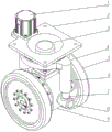
Fig. 1 is a schematic structural diagram of embodiment 1.
Fig. 2 is a front view of embodiment 1.
Fig. 3 is a cross-sectional view A-A of fig. 2.
Fig. 4 is a schematic structural diagram of embodiment 2.
Fig. 5 is a front view of embodiment 2.
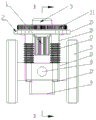
Fig. 6 is a B-B cross-sectional view of fig. 5.
Detailed Description
Example 1: as shown in fig. 1-3, a vehicle traveling driving direction navigation mechanism comprises a traveling driving assembly, a steering driving assembly, a damping assembly and a slewing support mounting frame 2, wherein the traveling driving assembly is connected with the steering driving assembly through the damping assembly.
The walking driving assembly comprises a walking driving motor 3, a differential mechanism 9 and a walking driving wheel 5, the walking driving motor 3 is arranged on the rotary support mounting frame 2, an output shaft of the walking driving motor 3 downwards penetrates through the rotary support mounting frame 2 to be connected with the differential mechanism 9, and two output shafts of the differential mechanism 9 are respectively connected with the walking driving wheel 5.
The steering driving assembly comprises a steering driving motor 1, a steering rotary disc 4 and a steering driving gear 10, wherein the steering driving motor 1 is arranged on the rotary support mounting frame 2, and an output shaft of the steering driving motor 1 is meshed with a steering rotary disc gear 11 on the steering rotary disc 4 through the steering driving gear 10; the steering rotary disk 4 is arranged on the rotary support mounting frame 2 and rotates around the rotary support mounting frame 2; the damper assembly is arranged between the steering wheel 4 and the differential gear 9 and connects the steering wheel 4 to the differential gear 9.
Specifically, the steering drive motor 1 is mounted on the upper end surface of the slewing bearing mounting frame 2, and an output shaft of the steering drive motor 1 downwards passes through a hole on the slewing bearing mounting frame 2 to be connected with the steering drive gear 10; the steering wheel 4 is fitted over the lower end surface of the slewing bearing mounting frame 2, and a steering wheel gear 11 is provided on the outer circumferential surface of the steering wheel 4.
The shock absorption assembly comprises a shock absorber 6 and shock absorber piston shafts 7, wherein the shock absorber 6 is symmetrically arranged on two sides of the steering rotary disk 4, and the upper ends of the shock absorber piston shafts 7 extend into the shock absorber 6 and are in contact with springs in the shock absorber 6; the lower end of the damper piston shaft 7 is sleeved on the outer shell of the differential mechanism 9.
The lower end of the shock absorber piston shaft 7 is provided with an ear hole 7-1, and the axis of the ear hole 7-1 is perpendicular to the axis of the shock absorber piston shaft 7; a lifting lug shaft 8 is arranged on the differential mechanism 9 shell, and the axis of the lifting lug shaft 8 is parallel to the axis of the lug hole 7-1 and perpendicular to the axis of the output shaft of the differential mechanism 9; the damper piston shaft 7 is engaged with a lug shaft 8 on the differential 9 through an ear hole 7-1 to connect the damper piston shaft 7 with the differential 9. The shock absorber piston shaft 7 generates shock absorption motion when the walking driving wheel 5 is impacted by load, and the transverse lug holes of the shock absorber piston shaft 7 can rotate and adjust by taking the lifting lug shaft 8 of the differential mechanism as an axis when the walking driving wheel 5 at two ends is inconsistent with the ground in height, so that the walking driving wheel 5 at two ends floats and fully contacts with the ground.
In an embodiment, the steering wheel gear 11 may be integrally formed with the steering wheel 4, and the damper 6 may be integrally formed with the steering wheel 4.
The working process comprises the following steps: during steering, the rotary support mounting frame 2 is used for being connected with external equipment, the steering driving motor 1 drives the steering driving gear 10 to rotate, the steering driving gear 10 is meshed with the steering rotary disk gear 11, the steering rotary disk gear 11 rotates around the rotary support mounting frame 2 together with the steering rotary disk 4, the shock absorber 6 and the shock absorber piston shaft 7 mounted at the side end of the steering rotary disk 4 rotate together with the steering rotary disk 4, and the shock absorber piston shaft 7 drives the differential mechanism 9 and the traveling driving wheels 5 thereof to rotate together because the lower end of the shock absorber piston shaft 7 is mounted on the shell of the differential mechanism 9, and the rotation angle is 0-360 degrees.
During walking, the walking driving motor 3 transmits power to the differential mechanism 9, and an output shaft of the differential mechanism 9 drives the walking driving wheel 5 to walk.
During walking, the damper piston shaft 7 cooperates with the spring to achieve a cushioning effect.
Example 2: as shown in fig. 4-6, a vehicle traveling driving direction navigation mechanism comprises a traveling driving assembly, a steering driving assembly, a damping assembly and a slewing support mounting frame 2, wherein the traveling driving assembly is connected with the steering driving assembly through the damping assembly.
The walking driving assembly comprises a walking driving motor 3, a differential mechanism 9 and a walking driving wheel 5, the walking driving motor 3 is arranged on the rotary support mounting frame 2, an output shaft of the walking driving motor 3 downwards penetrates through the rotary support mounting frame 2 to be connected with the differential mechanism 9, and two output shafts of the differential mechanism 9 are respectively connected with the walking driving wheel 5.
The steering driving assembly comprises a steering driving motor 1, a steering rotary disc 4 and a steering driving gear 10, wherein the steering driving motor 1 is arranged on the rotary support mounting frame 2, and an output shaft of the steering driving motor 1 is meshed with a steering rotary disc gear 11 on the steering rotary disc 4 through the steering driving gear 10; the steering rotary disk 4 is arranged on the rotary support mounting frame 2 and rotates around the rotary support mounting frame 2; the damper assembly is arranged between the steering wheel 4 and the differential gear 9 and connects the steering wheel 4 to the differential gear 9.
Specifically, the steering drive motor 1 is mounted on the lower end surface of the slewing bearing mounting frame 2, and an output shaft of the steering drive motor 1 upwards passes through a hole on the slewing bearing mounting frame 2 to be connected with the steering drive gear 10; the lower part of the steering rotary disk 4 is arranged in the rotary support mounting frame 2 and rotates around the rotary support mounting frame 2, a steering rotary disk gear 11 is arranged on the outer circumferential surface of the upper part of the steering rotary disk 4, the steering rotary disk gear 11 is meshed with a steering driving gear 10, and a workpiece mounting hole connected with other mechanisms is arranged at the upper end of the steering rotary disk 4.
The damping component comprises a guide column 16, an elastic damping sleeve 17 and a connecting block 18, a boss is arranged at the upper part of the guide column 16, the upper end of the guide column 16 is fixed on the lower end face of the rotary support mounting frame 2, and the lower end of the guide column 16 is inserted into the connecting block 18; the elastic damping sleeve 17 is sleeved on the guide post 16 and is positioned between the boss and the connecting block 18; the connection block 18 is hinged to the housing of the differential 9.
Guide column mounting holes are symmetrically formed in the upper end face of the connecting block 18, and the guide columns 16 are inserted into the guide column mounting holes; a lifting lug mounting hole 18-1 is formed in the front end face of the connecting block 18, and the axis of the lifting lug mounting hole 18-1 is perpendicular to the axis of the guide post mounting hole; the housing of the differential mechanism 9 is symmetrically provided with lifting lugs 8, and the axis of the lifting lug 8 is parallel to the axis of the lifting lug mounting hole 18-1 and perpendicular to the axis of the output shaft of the differential mechanism 9; the connecting block 18 is sleeved on the lifting lug shaft 8 through a lifting lug mounting hole 18-1.
Preferably, a slewing bearing steel ball 20 is provided at the contact of the steering wheel 4 with the slewing bearing mounting frame 2. The arrangement of the slewing bearing steel balls 20 reduces the rotational friction between the steering wheel 4 and the slewing bearing mounting frame 2.
Further preferably, the lower end of the guide post 16 is provided with a drop-off preventing backing plate 19.
During the operation, steering wheel 4 is connected with external equipment during steering, that is to say steering wheel 4 and steering wheel gear 11 are motionless, steering drive motor 1 drives steering drive gear 10 to rotate, steering drive gear 10 meshes with steering wheel gear 11, because steering wheel gear 11 and steering wheel 4 are motionless, steering drive gear 10 takes slewing support mounting bracket 2 to rotate around steering wheel gear 11, steering column 16 on slewing support mounting bracket 2 rotates thereupon, steering column 16 drives connecting block 18 to rotate together, connecting block 18 drives differential mechanism 9 and walking drive wheel 5 to rotate, and the rotation angle is 0~360 degrees.
During walking, the walking driving motor 3 transmits power to the differential mechanism 9, and an output shaft of the differential mechanism 9 drives the walking driving wheel 5 to walk.
During walking, the elastic damping sleeve 17 stretches to achieve a buffering effect.
Claims (5)
1. A vehicle travel drive direction navigation mechanism, characterized in that: the steering device comprises a walking driving assembly, a steering driving assembly, a damping assembly and a slewing support mounting frame (2), wherein the walking driving assembly is connected with the steering driving assembly through the damping assembly; the walking driving assembly comprises a walking driving motor (3), a differential mechanism (9) and a walking driving wheel (5), wherein the walking driving motor (3) is arranged on the rotary supporting installation frame (2), an output shaft of the walking driving motor (3) downwards penetrates through the rotary supporting installation frame (2) to be connected with the differential mechanism (9), and two output shafts of the differential mechanism (9) are respectively connected with the walking driving wheel (5); the steering driving assembly comprises a steering driving motor (1), a steering rotary disc (4) and a steering driving gear (10), wherein the steering driving motor (1) is arranged on the rotary supporting installation frame (2), and an output shaft of the steering driving motor (1) is meshed with a steering rotary disc gear (11) on the steering rotary disc (4) through the steering driving gear (10); the steering rotary disc (4) is arranged on the rotary support mounting frame (2); the damping component is arranged between the steering rotary disk (4) and the differential mechanism (9) and connects the steering rotary disk (4) with the differential mechanism (9); the damping component comprises a damper (6) and damper piston shafts (7), the damper (6) is symmetrically arranged on two sides of the steering rotary disc (4), and the upper ends of the damper piston shafts (7) extend into the damper (6) and are in contact with springs in the damper (6); the lower end of the damper piston shaft (7) is sleeved on the outer shell of the differential mechanism (9); the lower end of the damper piston shaft (7) is provided with an ear hole (7-1), and the axis of the ear hole (7-1) is perpendicular to the axis of the damper piston shaft (7); a lifting trunnion (8) is arranged on the casing of the differential mechanism (9), and the axis of the lifting trunnion (8) is parallel to the axis of the lug hole (7-1) and perpendicular to the axis of the output shaft of the differential mechanism (9); the damper piston shaft (7) is matched with the lifting lug shaft (8) on the differential mechanism (9) through the lug hole (7-1) to connect the damper piston shaft (7) with the differential mechanism (9), the steering rotary disc gear (11) and the steering rotary disc (4) are integrally formed, and the damper (6) and the steering rotary disc (4) are integrally formed.
2. The vehicle travel drive direction navigation mechanism according to claim 1, wherein: the steering driving motor (1) is arranged on the upper end surface of the slewing supporting installation frame (2), and an output shaft of the steering driving motor (1) downwards penetrates through a hole in the slewing supporting installation frame (2) to be connected with the steering driving gear (10); the steering rotary disk (4) is sleeved on the lower end surface of the rotary support mounting frame (2), and a steering rotary disk gear (11) is arranged on the outer circumferential surface of the steering rotary disk (4).
3. A vehicle travel drive direction navigation mechanism, characterized in that: the steering device comprises a walking driving assembly, a steering driving assembly, a damping assembly and a slewing support mounting frame (2), wherein the walking driving assembly is connected with the steering driving assembly through the damping assembly; the walking driving assembly comprises a walking driving motor (3), a differential mechanism (9) and a walking driving wheel (5), wherein the walking driving motor (3) is arranged on the rotary supporting installation frame (2), an output shaft of the walking driving motor (3) downwards penetrates through the rotary supporting installation frame (2) to be connected with the differential mechanism (9), and two output shafts of the differential mechanism (9) are respectively connected with the walking driving wheel (5); the steering driving assembly comprises a steering driving motor (1), a steering rotary disc (4) and a steering driving gear (10), wherein the steering driving motor (1) is arranged on the rotary supporting installation frame (2), and an output shaft of the steering driving motor (1) is meshed with a steering rotary disc gear (11) on the steering rotary disc (4) through the steering driving gear (10); the steering rotary disc (4) is arranged on the rotary support mounting frame (2); the damping component is arranged between the steering rotary disk (4) and the differential mechanism (9) and connects the steering rotary disk (4) with the differential mechanism (9); a rotary support steel ball (20) is arranged at the contact position of the steering rotary disk (4) and the rotary support mounting frame (2); the damping component comprises a guide column (16), an elastic damping sleeve (17) and a connecting block (18), a boss is arranged on the upper portion of the guide column (16), the upper end of the guide column (16) is fixed on the lower end face of the rotary support mounting frame (2), and the lower end of the guide column (16) is inserted into the connecting block (18); the elastic damping sleeve (17) is sleeved on the guide post (16) and is positioned between the boss and the connecting block (18); the connecting block (18) is hinged on the shell of the differential mechanism (9); guide column mounting holes are symmetrically formed in the upper end face of the connecting block (18), and guide columns (16) are inserted into the guide column mounting holes; a lifting lug mounting hole (18-1) is formed in the front end face of the connecting block (18), and the axis of the lifting lug mounting hole (18-1) is perpendicular to the axis of the guide post mounting hole; lifting lug shafts (8) are symmetrically arranged on the shell of the differential mechanism (9), and the axes of the lifting lug shafts (8) are parallel to the axes of the lifting lug mounting holes (18-1) and perpendicular to the axes of the output shafts of the differential mechanism (9); the connecting block (18) is sleeved on the lifting lug shaft (8) through the lifting lug mounting hole (18-1).
4. A vehicle travel drive direction navigation mechanism according to claim 3, wherein: the steering driving motor (1) is arranged on the lower end surface of the slewing supporting installation frame (2), and an output shaft of the steering driving motor (1) upwards penetrates through a hole in the slewing supporting installation frame (2) to be connected with the steering driving gear (10); the lower part of the steering rotary disk (4) is arranged in the rotary support mounting frame (2) and rotates around the rotary support mounting frame (2), a steering rotary disk gear (11) is arranged on the outer circumferential surface of the upper part of the steering rotary disk (4), the steering rotary disk gear (11) is meshed with a steering driving gear (10), and a workpiece mounting hole connected with other mechanisms is formed in the upper end of the steering rotary disk (4).
5. The vehicle travel drive direction navigation mechanism according to claim 4, wherein: the lower end of the guide post (16) is provided with an anti-falling backing plate (19).
Priority Applications (1)
| Application Number | Priority Date | Filing Date | Title |
|---|---|---|---|
| CN201710322876.1A CN106945467B (en) | 2017-05-09 | 2017-05-09 | Vehicle walking driving direction navigation mechanism |
Applications Claiming Priority (1)
| Application Number | Priority Date | Filing Date | Title |
|---|---|---|---|
| CN201710322876.1A CN106945467B (en) | 2017-05-09 | 2017-05-09 | Vehicle walking driving direction navigation mechanism |
Publications (2)
| Publication Number | Publication Date |
|---|---|
| CN106945467A CN106945467A (en) | 2017-07-14 |
| CN106945467B true CN106945467B (en) | 2023-07-07 |
Family
ID=59479465
Family Applications (1)
| Application Number | Title | Priority Date | Filing Date |
|---|---|---|---|
| CN201710322876.1A Active CN106945467B (en) | 2017-05-09 | 2017-05-09 | Vehicle walking driving direction navigation mechanism |
Country Status (1)
| Country | Link |
|---|---|
| CN (1) | CN106945467B (en) |
Families Citing this family (12)
| Publication number | Priority date | Publication date | Assignee | Title |
|---|---|---|---|---|
| CN108583727A (en) * | 2018-05-23 | 2018-09-28 | 江苏集萃智能制造技术研究所有限公司 | A kind of full landform rescue Disaster Relief Robot |
| WO2020059189A1 (en) * | 2018-09-21 | 2020-03-26 | 日本精工株式会社 | Drive wheel, carriage, and device |
| CN111319673A (en) * | 2018-12-13 | 2020-06-23 | 沈阳新松机器人自动化股份有限公司 | Driving mechanism capable of independently steering |
| CN109528102A (en) * | 2019-01-11 | 2019-03-29 | 浙江智澜科技有限公司 | One kind being based on unpiloted garden intelligence cleaning robot |
| CN110316279A (en) * | 2019-05-24 | 2019-10-11 | 广州市中立智能装备科技有限公司 | A kind of omnidirectional's differential driving steering wheel |
| CN110606142B (en) * | 2019-08-15 | 2020-09-25 | 燕山大学 | Series-parallel supporting leg based on ground sealing and movable posture adjusting platform thereof |
| WO2021027572A1 (en) * | 2019-08-15 | 2021-02-18 | 燕山大学 | Active-passive differential series-parallel supporting leg, gravity closing-based series-parallel supporting leg and six-degree-of-freedom posture adjustment robot platform |
| CN110512673A (en) * | 2019-08-29 | 2019-11-29 | 广东博智林机器人有限公司 | Evener |
| CN110562350A (en) * | 2019-09-24 | 2019-12-13 | 曹昂 | All-round eight rounds of cross country cars of differential wheel group structure |
| CN111577759A (en) * | 2020-04-29 | 2020-08-25 | 河南科技大学 | Large-scale carousel walking wheel with automatic compensation function |
| CN112282456B (en) * | 2020-10-22 | 2022-05-20 | 深圳精智机器有限公司 | Heavy-duty vehicle carrier and method |
| CN116518969B (en) * | 2023-04-25 | 2023-10-20 | 南京艾小宝智能科技有限公司 | Visual positioning system and method under indoor scene |
Citations (15)
| Publication number | Priority date | Publication date | Assignee | Title |
|---|---|---|---|---|
| GB191516798A (en) * | 1915-11-04 | 1919-03-27 | Eugene Schneider | Improved Power-transmitting and Steering Mechanism for Caterpillar Tractors. |
| JPH09301008A (en) * | 1996-05-08 | 1997-11-25 | Kawasaki Heavy Ind Ltd | Conveying truck provided with wheel with differential gear mechanism |
| CN201545061U (en) * | 2009-12-08 | 2010-08-11 | 东风汽车公司 | Assembly table vehicle for assembling production line |
| CN203172353U (en) * | 2013-04-12 | 2013-09-04 | 上海大学 | Universal wheel device |
| CN204264252U (en) * | 2014-11-28 | 2015-04-15 | 浙江上加机械有限公司 | Electronic power assist steering system |
| CN104527323A (en) * | 2014-12-17 | 2015-04-22 | 中国航空工业集团公司北京航空精密机械研究所 | Wheel set integrating driving function and steering function |
| KR20150067507A (en) * | 2013-12-10 | 2015-06-18 | (주)대성에스이 | A drive devic for automatic guided vehicle |
| CN104986220A (en) * | 2015-07-14 | 2015-10-21 | 上海英集斯自动化技术有限公司 | Unmanned carrying vehicle driving system |
| CN204775583U (en) * | 2015-05-28 | 2015-11-18 | 浙江上加机械有限公司 | Electronic heap of high car |
| CN105751892A (en) * | 2016-04-08 | 2016-07-13 | 浙江同筑科技有限公司 | Compact AGV (Automated Guided Vehicle) driving and steering integrated device |
| CN205387067U (en) * | 2016-02-23 | 2016-07-20 | 山西东杰智能物流装备股份有限公司 | Automatic double round differential drive unit for guided vehicles |
| CN205768620U (en) * | 2016-05-12 | 2016-12-07 | 吴昊 | Homing guidance formula Handling device |
| CN106515900A (en) * | 2016-10-10 | 2017-03-22 | 深圳市共进电子股份有限公司 | AGV mobile device |
| CN206125225U (en) * | 2016-09-21 | 2017-04-26 | 东莞市日博机电科技有限公司 | AGV differential drive unit |
| CN206781438U (en) * | 2017-05-09 | 2017-12-22 | 崔书林 | New vehicle hoofing part direction navigation sector |
-
2017
- 2017-05-09 CN CN201710322876.1A patent/CN106945467B/en active Active
Patent Citations (15)
| Publication number | Priority date | Publication date | Assignee | Title |
|---|---|---|---|---|
| GB191516798A (en) * | 1915-11-04 | 1919-03-27 | Eugene Schneider | Improved Power-transmitting and Steering Mechanism for Caterpillar Tractors. |
| JPH09301008A (en) * | 1996-05-08 | 1997-11-25 | Kawasaki Heavy Ind Ltd | Conveying truck provided with wheel with differential gear mechanism |
| CN201545061U (en) * | 2009-12-08 | 2010-08-11 | 东风汽车公司 | Assembly table vehicle for assembling production line |
| CN203172353U (en) * | 2013-04-12 | 2013-09-04 | 上海大学 | Universal wheel device |
| KR20150067507A (en) * | 2013-12-10 | 2015-06-18 | (주)대성에스이 | A drive devic for automatic guided vehicle |
| CN204264252U (en) * | 2014-11-28 | 2015-04-15 | 浙江上加机械有限公司 | Electronic power assist steering system |
| CN104527323A (en) * | 2014-12-17 | 2015-04-22 | 中国航空工业集团公司北京航空精密机械研究所 | Wheel set integrating driving function and steering function |
| CN204775583U (en) * | 2015-05-28 | 2015-11-18 | 浙江上加机械有限公司 | Electronic heap of high car |
| CN104986220A (en) * | 2015-07-14 | 2015-10-21 | 上海英集斯自动化技术有限公司 | Unmanned carrying vehicle driving system |
| CN205387067U (en) * | 2016-02-23 | 2016-07-20 | 山西东杰智能物流装备股份有限公司 | Automatic double round differential drive unit for guided vehicles |
| CN105751892A (en) * | 2016-04-08 | 2016-07-13 | 浙江同筑科技有限公司 | Compact AGV (Automated Guided Vehicle) driving and steering integrated device |
| CN205768620U (en) * | 2016-05-12 | 2016-12-07 | 吴昊 | Homing guidance formula Handling device |
| CN206125225U (en) * | 2016-09-21 | 2017-04-26 | 东莞市日博机电科技有限公司 | AGV differential drive unit |
| CN106515900A (en) * | 2016-10-10 | 2017-03-22 | 深圳市共进电子股份有限公司 | AGV mobile device |
| CN206781438U (en) * | 2017-05-09 | 2017-12-22 | 崔书林 | New vehicle hoofing part direction navigation sector |
Also Published As
| Publication number | Publication date |
|---|---|
| CN106945467A (en) | 2017-07-14 |
Similar Documents
| Publication | Publication Date | Title |
|---|---|---|
| CN106945467B (en) | Vehicle walking driving direction navigation mechanism | |
| CN206781438U (en) | New vehicle hoofing part direction navigation sector | |
| CN110962923B (en) | All-terrain suspension steering device | |
| CN202242852U (en) | Electric four-wheel traveling gear for robot | |
| CN206870775U (en) | Mobile platform | |
| CN216185444U (en) | Four-wheel-drive four-rotation robot wheel train structure | |
| CN106335542A (en) | Four-wheeled independent steering mechanism and working method | |
| CN100506582C (en) | Robot vehicle body suspension system | |
| CN214084426U (en) | Omnidirectional driving wheel mechanism | |
| CN101628420B (en) | Wheels of robot with driving and slip measuring capability adapted to rough ground | |
| CN108583191B (en) | Axle assembly for realizing active balance of vehicle body | |
| CN101524841B (en) | Flexible ellipse-like wheel of detection robot | |
| CN211223672U (en) | Four-wheel differential sliding steering power balancing device for independent suspension mobile robot | |
| CN110422010B (en) | Buffering mechanism for passive overturning of planetary wheel set | |
| CN210082858U (en) | Damping suspension device for AGV | |
| CN111645769A (en) | Crawler chassis floating thrust wheel structure and sugarcane harvester | |
| CN219821146U (en) | Vertical damping mechanism for driving wheel of omnidirectional mobile robot and robot | |
| CN107826171B (en) | Joint crawler belt with posture adjusting mechanism | |
| CN110562352A (en) | Four-wheel differential sliding steering power balancing device for independent suspension mobile robot | |
| CN218703595U (en) | Traveling device and mobile robot | |
| CN220096134U (en) | Steering wheel group capable of being towed in power failure | |
| CN213138964U (en) | Crawler chassis floating thrust wheel structure and sugarcane harvester | |
| CN211493575U (en) | A independently hang mechanism and heavy load AGV for AGV | |
| CN218112773U (en) | Mobile robot chassis | |
| CN220298596U (en) | Automobile steering connecting rod |
Legal Events
| Date | Code | Title | Description |
|---|---|---|---|
| PB01 | Publication | ||
| PB01 | Publication | ||
| SE01 | Entry into force of request for substantive examination | ||
| SE01 | Entry into force of request for substantive examination | ||
| GR01 | Patent grant | ||
| GR01 | Patent grant |