CN1069385C - torque transfer device - Google Patents
torque transfer device Download PDFInfo
- Publication number
- CN1069385C CN1069385C CN94107217A CN94107217A CN1069385C CN 1069385 C CN1069385 C CN 1069385C CN 94107217 A CN94107217 A CN 94107217A CN 94107217 A CN94107217 A CN 94107217A CN 1069385 C CN1069385 C CN 1069385C
- Authority
- CN
- China
- Prior art keywords
- flywheel
- axis
- friction
- accumulator
- cavity
- Prior art date
- Legal status (The legal status is an assumption and is not a legal conclusion. Google has not performed a legal analysis and makes no representation as to the accuracy of the status listed.)
- Expired - Lifetime
Links
Images


Classifications
-
- F—MECHANICAL ENGINEERING; LIGHTING; HEATING; WEAPONS; BLASTING
- F16—ENGINEERING ELEMENTS AND UNITS; GENERAL MEASURES FOR PRODUCING AND MAINTAINING EFFECTIVE FUNCTIONING OF MACHINES OR INSTALLATIONS; THERMAL INSULATION IN GENERAL
- F16H—GEARING
- F16H41/00—Rotary fluid gearing of the hydrokinetic type
-
- F—MECHANICAL ENGINEERING; LIGHTING; HEATING; WEAPONS; BLASTING
- F16—ENGINEERING ELEMENTS AND UNITS; GENERAL MEASURES FOR PRODUCING AND MAINTAINING EFFECTIVE FUNCTIONING OF MACHINES OR INSTALLATIONS; THERMAL INSULATION IN GENERAL
- F16F—SPRINGS; SHOCK-ABSORBERS; MEANS FOR DAMPING VIBRATION
- F16F15/00—Suppression of vibrations in systems; Means or arrangements for avoiding or reducing out-of-balance forces, e.g. due to motion
- F16F15/10—Suppression of vibrations in rotating systems by making use of members moving with the system
- F16F15/12—Suppression of vibrations in rotating systems by making use of members moving with the system using elastic members or friction-damping members, e.g. between a rotating shaft and a gyratory mass mounted thereon
- F16F15/131—Suppression of vibrations in rotating systems by making use of members moving with the system using elastic members or friction-damping members, e.g. between a rotating shaft and a gyratory mass mounted thereon the rotating system comprising two or more gyratory masses
-
- F—MECHANICAL ENGINEERING; LIGHTING; HEATING; WEAPONS; BLASTING
- F16—ENGINEERING ELEMENTS AND UNITS; GENERAL MEASURES FOR PRODUCING AND MAINTAINING EFFECTIVE FUNCTIONING OF MACHINES OR INSTALLATIONS; THERMAL INSULATION IN GENERAL
- F16F—SPRINGS; SHOCK-ABSORBERS; MEANS FOR DAMPING VIBRATION
- F16F1/00—Springs
- F16F1/02—Springs made of steel or other material having low internal friction; Wound, torsion, leaf, cup, ring or the like springs, the material of the spring not being relevant
- F16F1/32—Belleville-type springs
- F16F1/324—Belleville-type springs characterised by having tongues or arms directed in a generally radial direction, i.e. diaphragm-type springs
-
- F—MECHANICAL ENGINEERING; LIGHTING; HEATING; WEAPONS; BLASTING
- F16—ENGINEERING ELEMENTS AND UNITS; GENERAL MEASURES FOR PRODUCING AND MAINTAINING EFFECTIVE FUNCTIONING OF MACHINES OR INSTALLATIONS; THERMAL INSULATION IN GENERAL
- F16F—SPRINGS; SHOCK-ABSORBERS; MEANS FOR DAMPING VIBRATION
- F16F15/00—Suppression of vibrations in systems; Means or arrangements for avoiding or reducing out-of-balance forces, e.g. due to motion
- F16F15/10—Suppression of vibrations in rotating systems by making use of members moving with the system
- F16F15/12—Suppression of vibrations in rotating systems by making use of members moving with the system using elastic members or friction-damping members, e.g. between a rotating shaft and a gyratory mass mounted thereon
- F16F15/131—Suppression of vibrations in rotating systems by making use of members moving with the system using elastic members or friction-damping members, e.g. between a rotating shaft and a gyratory mass mounted thereon the rotating system comprising two or more gyratory masses
- F16F15/13142—Suppression of vibrations in rotating systems by making use of members moving with the system using elastic members or friction-damping members, e.g. between a rotating shaft and a gyratory mass mounted thereon the rotating system comprising two or more gyratory masses characterised by the method of assembly, production or treatment
- F16F15/1315—Multi-part primary or secondary masses, e.g. assembled from pieces of sheet steel
-
- F—MECHANICAL ENGINEERING; LIGHTING; HEATING; WEAPONS; BLASTING
- F16—ENGINEERING ELEMENTS AND UNITS; GENERAL MEASURES FOR PRODUCING AND MAINTAINING EFFECTIVE FUNCTIONING OF MACHINES OR INSTALLATIONS; THERMAL INSULATION IN GENERAL
- F16F—SPRINGS; SHOCK-ABSORBERS; MEANS FOR DAMPING VIBRATION
- F16F15/00—Suppression of vibrations in systems; Means or arrangements for avoiding or reducing out-of-balance forces, e.g. due to motion
- F16F15/10—Suppression of vibrations in rotating systems by making use of members moving with the system
- F16F15/12—Suppression of vibrations in rotating systems by making use of members moving with the system using elastic members or friction-damping members, e.g. between a rotating shaft and a gyratory mass mounted thereon
- F16F15/131—Suppression of vibrations in rotating systems by making use of members moving with the system using elastic members or friction-damping members, e.g. between a rotating shaft and a gyratory mass mounted thereon the rotating system comprising two or more gyratory masses
- F16F15/13164—Suppression of vibrations in rotating systems by making use of members moving with the system using elastic members or friction-damping members, e.g. between a rotating shaft and a gyratory mass mounted thereon the rotating system comprising two or more gyratory masses characterised by the supporting arrangement of the damper unit
-
- F—MECHANICAL ENGINEERING; LIGHTING; HEATING; WEAPONS; BLASTING
- F16—ENGINEERING ELEMENTS AND UNITS; GENERAL MEASURES FOR PRODUCING AND MAINTAINING EFFECTIVE FUNCTIONING OF MACHINES OR INSTALLATIONS; THERMAL INSULATION IN GENERAL
- F16F—SPRINGS; SHOCK-ABSORBERS; MEANS FOR DAMPING VIBRATION
- F16F15/00—Suppression of vibrations in systems; Means or arrangements for avoiding or reducing out-of-balance forces, e.g. due to motion
- F16F15/10—Suppression of vibrations in rotating systems by making use of members moving with the system
- F16F15/12—Suppression of vibrations in rotating systems by making use of members moving with the system using elastic members or friction-damping members, e.g. between a rotating shaft and a gyratory mass mounted thereon
- F16F15/131—Suppression of vibrations in rotating systems by making use of members moving with the system using elastic members or friction-damping members, e.g. between a rotating shaft and a gyratory mass mounted thereon the rotating system comprising two or more gyratory masses
- F16F15/139—Suppression of vibrations in rotating systems by making use of members moving with the system using elastic members or friction-damping members, e.g. between a rotating shaft and a gyratory mass mounted thereon the rotating system comprising two or more gyratory masses characterised by friction-damping means
- F16F15/1397—Overload protection, i.e. means for limiting torque
-
- F—MECHANICAL ENGINEERING; LIGHTING; HEATING; WEAPONS; BLASTING
- F16—ENGINEERING ELEMENTS AND UNITS; GENERAL MEASURES FOR PRODUCING AND MAINTAINING EFFECTIVE FUNCTIONING OF MACHINES OR INSTALLATIONS; THERMAL INSULATION IN GENERAL
- F16D—COUPLINGS FOR TRANSMITTING ROTATION; CLUTCHES; BRAKES
- F16D13/00—Friction clutches
- F16D13/58—Details
- F16D2013/581—Securing means for transportation or shipping
-
- F—MECHANICAL ENGINEERING; LIGHTING; HEATING; WEAPONS; BLASTING
- F16—ENGINEERING ELEMENTS AND UNITS; GENERAL MEASURES FOR PRODUCING AND MAINTAINING EFFECTIVE FUNCTIONING OF MACHINES OR INSTALLATIONS; THERMAL INSULATION IN GENERAL
- F16D—COUPLINGS FOR TRANSMITTING ROTATION; CLUTCHES; BRAKES
- F16D13/00—Friction clutches
- F16D13/58—Details
- F16D13/70—Pressure members, e.g. pressure plates, for clutch-plates or lamellae; Guiding arrangements for pressure members
- F16D2013/703—Pressure members, e.g. pressure plates, for clutch-plates or lamellae; Guiding arrangements for pressure members the pressure plate on the flywheel side is combined with a damper
-
- F—MECHANICAL ENGINEERING; LIGHTING; HEATING; WEAPONS; BLASTING
- F16—ENGINEERING ELEMENTS AND UNITS; GENERAL MEASURES FOR PRODUCING AND MAINTAINING EFFECTIVE FUNCTIONING OF MACHINES OR INSTALLATIONS; THERMAL INSULATION IN GENERAL
- F16D—COUPLINGS FOR TRANSMITTING ROTATION; CLUTCHES; BRAKES
- F16D13/00—Friction clutches
- F16D13/58—Details
- F16D13/70—Pressure members, e.g. pressure plates, for clutch-plates or lamellae; Guiding arrangements for pressure members
- F16D2013/706—Pressure members, e.g. pressure plates, for clutch-plates or lamellae; Guiding arrangements for pressure members the axially movable pressure plate is supported by leaf springs
Landscapes
- Engineering & Computer Science (AREA)
- General Engineering & Computer Science (AREA)
- Mechanical Engineering (AREA)
- Physics & Mathematics (AREA)
- Acoustics & Sound (AREA)
- Aviation & Aerospace Engineering (AREA)
- Manufacturing & Machinery (AREA)
- Mechanical Operated Clutches (AREA)
- Arrangement Of Transmissions (AREA)
- One-Way And Automatic Clutches, And Combinations Of Different Clutches (AREA)
Abstract
本发明涉及一种转矩传递装置,其具有至少两个借助周向作用的储力器相对减振装置产生相反作用力并通过支承可相互转动的飞轮质量,其中包括与内燃机从动轴连接的第一飞轮质量和通过摩擦离合器与传动机构的驱动轴连接的第二飞轮质量。
The invention relates to a torque transmission device having at least two flywheel masses which are counteracted by means of a circumferentially acting force store against a damper and which are rotatable relative to each other by means of a support, including a flywheel mass which is connected to the driven shaft of an internal combustion engine A first flywheel mass and a second flywheel mass are connected to the drive shaft of the transmission via a friction clutch.
Description
本发明涉及一种转矩传递装置,其具有至少两个与具有周向作用的储力器的减振装置作用相反的并且借助支承可相互转动的飞轮质量,其中第一飞轮质量可与内燃机的从动轴连接,而第二飞轮质量可通过摩擦离合器与传动机构的驱动轴连接。The invention relates to a torque transmission device having at least two flywheel masses which act oppositely to a damping device with a force store acting in the circumferential direction and which are mutually rotatable by means of a support, wherein the first flywheel mass is rotatable with the internal combustion engine The driven shaft is connected, while the second flywheel mass can be connected via a friction clutch to the drive shaft of the transmission.
GB2178824A公开了一种扭矩传递装置,该装置包括两个分开的飞轮,以及将二飞轮对中连接的轴承,但是这种传递装置的缺点在于,结构不够紧凑,而且组装和运输均不是非常方便。GB2178824A discloses a torque transmission device, which includes two separate flywheels and a bearing connecting the two flywheels. However, the disadvantage of this transmission device is that the structure is not compact enough, and the assembly and transportation are not very convenient.
本发明的目的是提供一种转矩传递装置,该装置的突出优点在于在轴向以及径向上减小了对空间的需要。此外它还显示出这样的可能性,即在给定的结构空间中实现尽可能大的摩擦离合器有效摩擦直径或在所需的摩擦直径内使整个装置保持紧凑的尺寸。本发明的另一个任务是,提高这种转矩传递装置的寿命和由此使其能有效地用于例如机动车中。The object of the present invention is to provide a torque transmission device which is particularly advantageous in that it requires less space in the axial and radial directions. Furthermore, it shows the possibility of realizing the largest possible effective friction diameter of the friction clutch in a given installation space or of keeping the overall arrangement compact in size within the required friction diameter. A further object of the invention is to increase the service life of such a torque transmission device and thus enable its efficient use, for example, in a motor vehicle.
根据本发明将实现,使储力器设置在摩擦离合器摩擦表面的径向内侧并在一个至少基本上封闭的且在周向上伸展的空腔中。According to the invention it is achieved that the force store is arranged radially inside the friction surface of the friction clutch in an at least substantially closed cavity extending in the circumferential direction.
本发明提出的另一个目的是,用尽可能简单的方式将转矩传递装置作为一个单元固定到内燃机的从动轴上。此外应该能够进行成本低和经济地生产并且能在该条件下实现这种转矩传递装置的装配。Another object set forth by the invention is to fasten the torque transmission device as a unit to the driven shaft of the internal combustion engine in the simplest possible manner. In addition, cost-effective and economical production should be possible and assembly of such a torque transmission device should be possible under these conditions.
本发明提出的另一个目的是,减少单个部件的数量和此外通过使用尽可能少的材料和尽可能减少材料浪费来保护自然资源,并且通过减少加工过程可以使环境在节省能源和减少迄今为止所用的附助加工的情况下得到保护。Another object proposed by the invention is to reduce the number of individual parts and moreover to preserve natural resources by using as little material as possible and minimizing material waste, and by reducing manufacturing processes the environment can benefit from saving energy and reducing the hitherto used Protected in case of secondary processing.
本发明的另一个目的是,防止在转矩传递装置的部件上产生过度转矩并从而避免这种过高转矩继续在与传矩传递装置附加连接的传动机构中的传递。A further object of the invention is to prevent the generation of excessive torques on components of the torque transmission device and thus to avoid the further transmission of such excessive torques in the gear train additionally connected to the torque transmission device.
本发明提出一种转矩传递装置包括:可与发动机的旋转输出部分连接的第一飞轮、可与第一飞轮绕同一轴线同时转动或相对于第一飞轮转动的第二飞轮、安装在两个飞轮之同可使两个飞轮相对同心的轴承;所述第二飞轮在距所述轴线第一径向距离处带有至少一个摩擦表面,第二飞轮通过摩擦离合器可与传动机构的旋转输入部分连接,其中:The present invention proposes a torque transmission device comprising: a first flywheel that can be connected with the rotary output part of the engine, a second flywheel that can rotate around the same axis with the first flywheel or rotate relative to the first flywheel, and is installed on two The bearings of the flywheels can make the two flywheels relatively concentric; the second flywheel has at least one friction surface at a first radial distance from the axis, and the second flywheel can be connected with the rotation input part of the transmission mechanism through a friction clutch connection, where:
所述装置还包括带有至少一个减震器可平衡两个飞轮相对转动的装置,所述减震器在距所述轴线较近的第二径向距离处带有至少两个储力器,在所述轴线方向上观察所述至少两个储力器至少部分位于所述第二飞轮之内,利用设置在储力器内侧径向分布的固定装置可将第一和第二飞轮固定在输出部分上。The device also includes means for balancing the relative rotation of the two flywheels with at least one shock absorber having at least two accumulators at a second radial distance closer to said axis, The at least two power accumulators are at least partly located inside the second flywheel as viewed in the direction of the axis, and the first and second flywheels can be fixed at the output by means of fixing devices arranged radially inside the power accumulators. partly on.
本发明还提出一种转矩传递装置包括:可与发动机的旋转输出部分连接的第一飞轮、可与第一飞轮绕同一轴线同时转动或相对于第一飞轮转动的第二飞轮、安装在两个飞轮之间可使两个飞轮相对同心的轴承;所述第二飞轮在距所述轴线第一径向距离处带有至少一个摩擦表面,第二飞轮通过摩擦离合器可与传动机构的旋转输入部分连接,其中:The present invention also proposes a torque transmission device comprising: a first flywheel that can be connected with the rotation output part of the engine, a second flywheel that can rotate around the same axis as the first flywheel or rotate relative to the first flywheel, and is installed on both sides. The two flywheels can be relatively concentric bearings between the two flywheels; the second flywheel has at least one friction surface at a first radial distance from the axis, and the second flywheel can be input with the rotation of the transmission mechanism through a friction clutch. Partial connection, where:
所述装置还包括带有至少一个减震器可平衡两个飞轮相对转动的装置,所述减震器在距所述轴线较近的第二径向距离处带有至少两个分布在所述飞轮周向方向的储力器,在所述轴线方向上观察所述至少两个储力器至少部分位于所述第二飞轮之内,在飞轮之间设有与储力器串联安装的滑动离合器。The device also includes means for balancing the relative rotation of the two flywheels with at least one shock absorber, at a second radial distance closer to the axis, with at least two Power accumulators in the circumferential direction of the flywheel, the at least two power accumulators are located at least partially inside the second flywheel as viewed in the axial direction, and a slip clutch installed in series with the power accumulators is provided between the flywheels .
本发明又提出一种转矩传递装置包括:可与主发动机的旋转输出部分连接的第一飞轮、可与第一飞轮绕同一轴线同时转动或相对于第一飞轮转动的第二飞轮、安装在两个飞轮之间可使两个飞轮相对同心的轴承;第二飞轮在距所述轴线第一径向距离处带有至少一个摩擦表面,第二飞轮通过摩擦离合器可与传动机构的旋转输入部分连接,其中:The present invention also proposes a torque transmission device comprising: a first flywheel that can be connected with the rotation output part of the main engine, a second flywheel that can rotate around the same axis with the first flywheel or rotate relative to the first flywheel, and installed on The bearing between two flywheels can make the two flywheels relatively concentric; the second flywheel has at least one friction surface at a first radial distance from said axis, and the second flywheel can be connected with the rotation input part of the transmission mechanism through a friction clutch connection, where:
所述装置包括带有至少一个减震器可平衡两个飞轮相对转动的装置,所述减震器在距所述轴线较近的第二径向距离处带有至少两个分布在所述飞轮周向方向的储力器,轴承的安装位置是在将第一飞轮固定在输出部分上的固定装置的位置的径向内侧。The device comprises means for balancing the relative rotation of two flywheels with at least one shock absorber with at least two For the accumulator in the circumferential direction, the mounting position of the bearing is radially inward of the position of the fixing means for fixing the first flywheel on the output part.
本发明另外提出一种可在旋转的输入部分和旋转的输出部分之同传递转矩的装置,包括:(a)可绕同一轴线转动或彼此相对转动的第一飞轮和第二飞轮,(b)安装在两个飞轮之间可使两个飞轮相对同心的轴承,(c)可将所述第一飞轮固定在旋转的输出部分上的装置,(d)带有设置在距所述轴线第一径向距离处的环形摩擦表面的摩擦离合器,所述第二飞轮带有摩擦表面并可以通过所述摩擦离合器与旋转的输入部分连接,输入部分带有设置在距所述轴线径向距离处的外形部分;The present invention further proposes a device capable of transmitting torque between a rotating input portion and a rotating output portion, comprising: (a) a first flywheel and a second flywheel capable of rotating around the same axis or relative to each other, (b ) a bearing mounted between two flywheels to make the two flywheels relatively concentric, (c) means to fix said first flywheel on the output part of rotation, (d) a bearing arranged at a distance from said axis a friction clutch of an annular friction surface at a radial distance, said second flywheel has a friction surface and can be connected via said friction clutch to a rotating input part with a friction clutch arranged at a radial distance from said axis part of the shape;
其中,所述装置还包括:(e)带有至少一个减震器可平衡两个飞轮相对转动的装置,所述减震器带有至少两个由所述轴线方向观察时处于所述摩擦表面的径向内侧的储力器,位于所述第一飞轮和所述储力器之间的输入部分和位于所述储力器和所述第二飞轮之间的输出部分,和(f)形成所述的能容纳至少所述储力器等部分的空间的空腔,所述储力器设置在距轴线第二径向距离处,输入部分带有设置在距所述轴线第三径向距离处的外形部分,所述轴承设置在距所述轴线第四径向距离处,所述固定装置设置在所述储力器和所述轴承之同的距所述轴线第五径向距离处,所述空腔带有设置在距所述轴线第六径向距离处的第一部分,所述空腔还带有设置在距所述轴线第七径向距离处的第二部分,所述七个距离中的至少四个彼此不相等。Wherein, the device further includes: (e) a device with at least one shock absorber capable of balancing the relative rotation of the two flywheels, the shock absorber having at least two an accumulator radially inward of , an input portion between said first flywheel and said accumulator and an output portion between said accumulator and said second flywheel, and (f) forming Said cavity capable of accommodating at least part of said power accumulator, said power accumulator disposed at a second radial distance from the axis, the input part having a space disposed at a third radial distance from said axis the profile portion at, said bearing is arranged at a fourth radial distance from said axis, said fixing device is arranged at a fifth radial distance from said axis between said accumulator and said bearing, Said cavity has a first portion disposed at a sixth radial distance from said axis, said cavity also has a second portion disposed at a seventh radial distance from said axis, said seven At least four of the distances are not equal to each other.
本发明所述的转矩传递装置的优点是,空腔至少围绕储力器的径向外侧区域。An advantage of the torque transmission device according to the invention is that the cavity surrounds at least the radially outer region of the force store.
此外,比较合适的是,空腔至少在径向外侧区中紧靠储力器的轮廓上。Furthermore, it is expedient if the cavity abuts the contour of the force store at least in the radially outer region.
本发明所述转矩传递装置的优选实施例表明,空腔至少由两个壁构成,两个壁中至少有一个与第二飞轮质量相连。A preferred embodiment of the torque transmission device according to the invention shows that the cavity is formed by at least two walls, at least one of which is connected to the second flywheel mass.
一般说来比较合适的是,至少一个空腔壁支撑第二飞轮质量。It is generally expedient if at least one cavity wall supports the second flywheel mass.
本发明所述的转矩传递装置还具有这样的优点,例如根据需要,可以采用滑动轴承或在另一种情况下采用滚动轴承作为支承。The torque transmission device according to the invention also has the advantage that, for example, sliding bearings or, alternatively, rolling bearings can be used as supports, if desired.
另一个优点是,所用的储力器由螺旋弹簧构成,此外也可以使用蝶形弹簧。Another advantage is that the force store used is formed as a helical spring, but also leg springs can be used.
在本发明所述的转矩传递装置中还显示出这样的优点,空腔至少在径向内侧是基本上密封的而且至少在局部区域上填有干式润滑剂,例如石墨粉,同时比较合适的是,可以用一个迷宫式密封装置对空腔进行例如防尘密封。In the torque transmission device according to the invention, it is also advantageous that the cavity is substantially sealed at least radially on the inside and is at least partially filled with a dry lubricant, such as graphite powder, which is also suitable Advantageously, a labyrinth seal can be used to seal the cavity, for example against dust.
本发明所述转矩传递装置可以用这样的优选方式构成,即空腔至少是基本密封的而且至少在其局部区域上填充粘稠的/膏状介质,由此在摩擦离合器摩擦表面的径向内侧上构成由空腔形成的油脂腔。The torque transmission device according to the invention can be constructed in such a preferred manner that the cavities are at least substantially sealed and at least partially filled with a viscous/pasty medium, whereby in the radial direction of the friction surfaces of the friction clutch On the inner side, a grease chamber formed by the cavity is formed.
此外比较合适的是,在空腔的内侧设置支承装置,由此使支承装置与润滑剂形成接触或者使支承处于油脂腔的内侧。Furthermore, it is expedient to arrange the bearing device on the inside of the cavity, so that the bearing device comes into contact with the lubricant or the bearing is located inside the grease chamber.
一般来说还具有优点的是,将支承装置设置在储力器的径向内侧。It is generally also advantageous to arrange the bearing device radially on the inside of the force store.
一个本发明所述转矩传递装置的优选实施例是这样构成的,即构成第二空腔壁的薄板在储力器的径向外侧与构成一空腔壁的薄板例如通过焊接或卷边而固定连接,其中比较合适的是,在空腔壁之间采用O型圈进行密封连接。A preferred embodiment of the torque transmission device according to the invention is constructed in such a way that the thin plate forming the second cavity wall is fastened radially outside the force accumulator to the thin plate forming a cavity wall, for example by welding or crimping connection, where it is more appropriate to use an O-ring between the walls of the cavity for sealing connection.
本发明所述转矩传递装置的突出特点在于,构成空腔壁的薄板上具有用于储力器的加载区,其中在合适的方式中加载区是通过相互指向的轴向冲制构成的,这些冲制件在储力器之间的空间中轴向突出。The torque transmission device according to the invention is characterized in that the thin plates forming the walls of the cavity have loading areas for the force accumulator, wherein the loading areas are formed in a suitable manner by mutually directed axial punching, These stamped parts protrude axially in the space between the force accumulators.
一个特别好的优点是,在本发明的转矩传递装置中,薄板与第二飞轮质量相连,其中它的合理之处在于,薄板与第二飞轮质量上背离摩擦面的一侧相铰接,从而在后边卡住对置压板。A particularly advantageous advantage is that, in the torque transmission device according to the invention, the thin plate is connected to the mass of the second flywheel, wherein it is rational in that the thin plate is hinged to the side of the second flywheel mass facing away from the friction surface, so that Clamp the opposing pressure plate at the rear.
薄板与第二飞轮质量可以通过结构配合、摩擦配合或力配合的形式相连接。The thin plate and the mass of the second flywheel can be connected in the form of structural fit, friction fit or force fit.
一般说来在转矩传递装置中特别有利的是,将转矩传递装置或滑动离合器这样设置力传递行程,即使得转矩链(流)这样形成,从马达方向看,从第一飞轮质量通过一个进入空腔中且对储力器加载的法兰件传到储力器,从储力器到空腔壁,再从空腔壁到达设在储力器径向外侧的转矩限制机构的摩擦面上,但是该摩擦表面径向上位于摩擦离合器的径向外部摩擦区域内侧,或者在径向上仅仅稍微嵌入摩擦离合器的径向外部摩擦区域内,再从该转矩限制机构的摩擦表面传递到第二飞轮质量。Generally speaking, in torque transmission devices it is particularly advantageous to arrange the force transmission stroke of the torque transmission device or slip clutch in such a way that the torque chain (flow) is formed in such a way that, viewed from the direction of the motor, the first flywheel mass passes through A flange that enters the cavity and loads the accumulator is transmitted to the accumulator, from the accumulator to the cavity wall, and then from the cavity wall to the torque limiting mechanism located on the radially outer side of the accumulator friction surface, but the friction surface is located radially inside the radially outer friction area of the friction clutch, or is only slightly embedded in the radial direction in the radially outer friction area of the friction clutch, and then is transmitted from the friction surface of the torque limiting mechanism to Second flywheel mass.
此外其优点还在于,使摩擦配合的连接装置在轴向上张紧,其中可由碟簧产生轴向张紧所需的轴向力。Furthermore, it has the advantage that the friction-fit connection is tensioned in the axial direction, wherein the axial force required for the axial tensioning can be generated by the disk spring.
合适的是,通过操作碟簧来改变轴向力,其中优选的方式是,通过第一飞轮质量来形成对碟簧的操作。为此可以将操作元件与第一飞轮质量制成一体。Expediently, the axial force is varied by actuating the disc spring, wherein preferably the actuation of the disc spring is formed by the first flywheel mass. For this purpose, the operating element can be integrated into the first flywheel mass.
所表现出的有利方面在于,在本发明所述的转矩传递装置上,将薄板与第二飞轮质量通过摩擦材料的中间层而相互连接,除此之外摩擦材料还作为绝热材料。It is an advantage that, in the torque transmission device according to the invention, the sheet metal and the second flywheel mass are connected to each other via an intermediate layer of friction material, which also serves as a heat insulating material.
进一步的优点还在于,构成空腔壁的薄板由轴承装置所支承或可支撑在轴承上。A further advantage is also that the thin plates forming the walls of the cavity are supported by the bearing arrangement or can be supported on bearings.
对于本发明所述的转矩传递装置来说特别好的优点在于,另一方面储力器支撑在加载区上,加载区设置在伸入空腔中的法兰上,该法兰(一个或多个)在储力器的径向内侧与第一飞轮相连,其中合适的是,一个或多个法兰与第一飞轮质量的连接通过采用固定螺钉来实现,固定螺钉起到将第一飞轮质量或转矩传递装置与内燃机的从动轴相连接的作用。A particularly advantageous advantage for the torque transmission device according to the invention is that, on the other hand, the force store is supported on a load zone, which is arranged on a flange protruding into the cavity, which flange (one or multiple) are connected to the first flywheel on the radially inner side of the force accumulator, wherein suitably, the connection of one or more flanges to the mass of the first flywheel is realized by using fixing screws, which serve to connect the first flywheel The role of a mass or torque transmitting device in connection with the driven shaft of an internal combustion engine.
根据本发明的转矩传递装置的一个合适的实施例,可以设置两个法兰,两法兰在外径区域上相互固定连接。According to a suitable embodiment of the torque transmission device according to the invention, two flanges can be provided which are fixedly connected to each other in the region of the outer diameter.
除此之外其优点还在于,两个法兰在用于将装置固定到曲轴上的螺钉区域中相互靠紧。In addition, this has the advantage that the two flanges abut against each other in the region of the screws for fastening the device to the crankshaft.
其合理之处还体现在,两个法兰在固定螺钉和法兰外径之间的径向区域中轴向上相互隔开一定间隙。This is also justified in that the two flanges are axially spaced from one another by a certain play in the radial region between the fastening screw and the outer diameter of the flange.
一般对转矩传递装置来说特别有利的是,与第一飞轮质量相连的多个法兰或与该飞轮质量相连的一个法兰的加载区与由螺旋弹簧构成的储力器相配合,弹簧的螺旋端圈结构实际上与中部弹簧圈相同。因此弹簧端部即不贴紧又不进行磨削,而是仅仅呈展开状或呈“切断”状。In general, it is particularly advantageous for the torque transmission device that the flanges connected to the first flywheel mass or the loading area of a flange connected to the flywheel mass cooperate with a force accumulator consisting of a helical spring, the spring The helical end coil construction is virtually the same as the middle coil. The spring ends are therefore neither tight nor ground, but merely unfolded or "cut off".
更合适的是,一个法兰或多个法兰的加载区相对于相互构成的内弹簧和外弹簧形成阶梯形。Advantageously, the load zone of the flange or flanges is stepped with respect to the inner and outer springs which form one another.
更有利的是,薄板上具有相对于内弹簧和外弹簧形成阶梯形的加载区,其中加载区是以合适的方式通过双重收缩而形成的。It is further advantageous if the thin plate has a stepped loading zone with respect to the inner spring and the outer spring, wherein the loading zone is formed in a suitable manner by double contraction.
本发明所述的转矩传递装置显示出的优点在于,第一飞轮质量和法兰之间直接通过配合结构来对中。The torque transmission device according to the invention exhibits the advantage that the centering between the first flywheel mass and the flange is directly via a mating structure.
其优点还在于,法兰上具有用于使转矩传递装置在内燃机的从动轴上对中的对中支座。It is also advantageous that the flange has a centering seat for centering the torque transmission device on the output shaft of the internal combustion engine.
例如对于本发明所述转矩传递的结构而言,法兰支撑着轴承装置。For example in the case of the torque transmission according to the invention, the flange supports the bearing arrangement.
特别好的优点是,本发明所述的转矩传递装置具有两个用于使储力器加载的法兰,其中一个法兰的作用是将转矩传递装置固定到内燃机的从动轴上,并使转矩传递装置与从动轴对中,接纳轴承以及使第一飞轮质量对中。It is particularly advantageous that the torque transmission device according to the invention has two flanges for loading the force accumulator, one of which serves to fasten the torque transmission device to the driven shaft of the internal combustion engine, And align the torque transfer device with the driven shaft, accept the bearings and align the first flywheel mass.
本发明所述转矩传递装置的一个优选实施例中具有一个以碟簧部件的形式置于径向内侧上的空腔密封件,碟簧部件一方面与构成空腔壁的薄板或与薄板相连的部件相互作用,另一方面与和其相邻的法兰或与其相连接的部件相互作用。A preferred embodiment of the torque transmission device according to the invention has a cavity seal arranged radially on the inside in the form of a disk spring element, which is connected on the one hand to the sheet forming the cavity wall or to the sheet On the other hand, it interacts with its adjacent flange or the parts connected to it.
适合于例如以预安装模式构成的转矩传递装置是,一个与法兰相连接且与碟簧型密封件相互作用的部件起固定螺旋弹簧的作用。It is suitable, for example, to construct the torque transmission device in a pre-assembled mode in which a part connected to the flange and interacting with the disc spring-type seal acts as a fixed helical spring.
在这种情况下的优点是,薄板上具有用于使固定螺钉穿过或用于使一个工具通过以便操作固定螺钉的开口,其中比较合适的是,将开口用裙边包住,该裙边与碟簧型密封装置相互作用。The advantage in this case is that the sheet has an opening for passing the fixing screw or for passing a tool in order to manipulate the fixing screw, wherein it is expedient to surround the opening with a skirt which Interacts with disc spring type seals.
除此之外,碟簧型密封件还设有摩擦减振装置,该装置有利于降低成本。In addition, the disc spring type seal is also equipped with a friction damping device, which is beneficial to reduce costs.
根据本发明的转矩传递装置的优选实施例,其突出的特点在于,储力器、空腔以及设置在第二飞轮质量上的摩擦离合器的摩擦表面均安置于相同的轴向区域内,而且在轴向上相互重叠。A preferred embodiment of the torque transmission device according to the invention is characterized in that the force accumulator, the cavity and the friction surfaces of the friction clutch arranged on the second flywheel mass are arranged in the same axial area, and axially overlap each other.
此外,有利于例如使整个装置结构紧凑的优点是,将轴承和固定螺钉的头部设置在相同的轴向区域。Furthermore, it is advantageous, for example, to make the overall arrangement compact if the bearing and the head of the fixing screw are arranged in the same axial region.
对本发明所述的转矩传递装置特别有利的是,将力存储器(或空腔)径向上设置在固定螺钉的头部和设在第二飞轮质量上的摩擦离合器的摩擦面之间。It is particularly advantageous for the torque transmission device according to the invention if the force accumulator (or cavity) is arranged radially between the head of the fastening screw and the friction surface of the friction clutch arranged on the second flywheel mass.
比较合适的是,在根据本发明所述的转矩传递装置中,在空腔中对着固定螺钉头部的一侧上设有一个壁。Advantageously, in the torque transmission device according to the invention, a wall is provided in the cavity on the side facing the head of the fixing screw.
普遍说来,转矩传递装置的一个特别优选的结构形式是由以下按径向排列的7个部件中的至少4个部件构成的:Generally speaking, a particularly preferred embodiment of the torque transmission device is formed by at least 4 of the following 7 components arranged radially:
--传动轴的轮廓,-- the profile of the drive shaft,
--支承装置--Support device
--固定螺钉头部-- Fixing screw head
--径向内侧的空腔壁-- Radially inner cavity wall
--储力器-- Power accumulator
--径向外侧的空腔壁-- radially outer cavity wall
--第二飞轮质量的摩擦面其中上述部件的布局可以在不同直径区域上且不重叠地形成。- The friction surface of the second flywheel mass wherein the layout of the above components can be formed on areas of different diameters without overlapping.
更合适的是,将部件(至少四个)设置在相同的轴向区域内。More suitably, the parts (at least four) are arranged in the same axial region.
在本发明所述的转矩传递装置中表现出的特别好的优点在于,将支承装置设置在固定螺钉头部的径向里侧。A particularly advantageous advantage of the torque transmission device according to the invention is that the bearing device is arranged radially inside the head of the fixing screw.
将固定螺钉头布置在轴承和储力器之间与一个其中储力器和固定螺钉头相靠近或位于相同轴向区中的转矩传递装置结构具有同样的优点。Arranging the fixing screw head between the bearing and the force store has the same advantages as a construction of the torque transmission device in which the force store and the fixing screw head are located close together or in the same axial region.
此外比较合适的是,将构成空腔的壁径向设置在储力器和固定螺钉的头部之间。Furthermore, it is expedient to arrange the wall forming the cavity radially between the force store and the head of the fastening screw.
对某些应用场合比较合适的是,将支承装置设置在固定螺钉头部的径向外侧。For some applications it is expedient to arrange the bearing means radially outside the head of the fixing screw.
在本发明所述的转矩传递装置中特别有利的是,减振装置的储力器具有4-10范围内的长度直径比,即具有较大的长度直径比。In the case of the torque transmission device according to the invention it is particularly advantageous if the force store of the damper device has a length-to-diameter ratio in the range of 4-10, ie has a relatively large length-to-diameter ratio.
更有利的是,储力器在周向区域的延伸量为(周长的)70%-95%,最好约为80%-90%。More advantageously, the force store extends in the circumferential region by 70%-95% (of the circumference), preferably approximately 80%-90%.
合理之处体现在,至少一个储力器的周向延伸范围大于140°。The rationale is that the circumferential extension of at least one force store is greater than 140°.
在本发明所述的转矩传递装置的特别有利之处在于,将储力器弯曲成至少具有与安装状态相应的半径。The torque transmission device according to the invention is particularly advantageous in that the force store is bent at least with a radius corresponding to the installed state.
根据本发明所述的转矩传递装置,在不同的实施例中可以有多种弹簧类型。Various spring types are possible in different embodiments of the torque transmitting device according to the present invention.
一般说来,在转矩传递装置中特别有利的是,螺旋弹簧形式的储力器的端部弹簧圈基本上与其中部的弹簧圈相一致,它既不被磨削也不会贴紧前面的圈,而是仅仅在与钢丝截面大约垂直的平面区上使其分开成将其“切断”。In general, it is particularly advantageous in torque transmission devices if the end coils of the accumulator in the form of a helical spring substantially coincide with the central coils, which are neither ground nor pressed against the front coils. Instead of loops, it is only "cut" by separating them in a planar region approximately perpendicular to the cross-section of the wire.
在本发明所述的转矩传递装置中可以合适的方式在储力器和空腔壁的径向外侧之间设置一个磨损保护装置,储力器至少在离心力作用下支撑在磨损保护装置上。In the torque transmission device according to the invention, a wear protection device can be arranged in a suitable manner between the force store and the radially outer side of the cavity wall, the force store being supported on the wear protection device at least under the action of centrifugal force.
在本发明所述的转矩传递装置中其合理性体现在,摩擦离合器的盖体在第二飞轮质量上对中。This is justified in the case of the torque transmission device according to the invention in that the cover of the friction clutch is centered on the second flywheel mass.
另一个优点是,摩擦离合器的盖体在轴向上包住第二飞轮质量,其中摩擦离合器的盖体可以其轴向布置的和包住第二飞轮质量的区域与第二飞轮质量相对中。A further advantage is that the cover of the friction clutch surrounds the second flywheel mass in the axial direction, wherein the cover of the friction clutch can be centered opposite the second flywheel mass in its axially arranged region surrounding the second flywheel mass.
在本发明所述的转矩传递装置中比较合理的是,盖体与第二飞轮质量是通过焊接而固定地、不可拆卸或不可分开地相连的。In the case of the torque transmission device according to the invention it is expedient if the cover is fixedly, non-detachably or non-detachably connected to the second flywheel mass by welding.
对另一个实施例比较合适的是,盖体与第二飞轮质量可通过例如螺钉或销钉进行可分式连接。It is suitable for another embodiment that the cover body and the second flywheel mass can be detachably connected by eg screws or pins.
另一种合理性还表现在,转矩传递装置是这样构成的,即例如象德国专利申请P4232320中所描述的那样,盖体本身是可分开的,以便于更换离合器盘。Another rationale is that the torque transmission device is constructed in such a way that the cover itself is detachable, for example as described in German patent application P4232320, in order to facilitate the replacement of the clutch disc.
本发明所述转矩传递装置的优点是,摩擦离合器的离合器盘上的支撑板至少基本与空腔的轮廓相适应。An advantage of the torque transmission device according to the invention is that the support plate on the clutch disk of the friction clutch is at least substantially adapted to the contour of the cavity.
相应的优选方式的转矩传递装置还具有一个润滑剂挡板和/或润滑剂阻挡轮廓,其位于离合器盘的支撑板上和/或对着离合器盘构成一个空腔壁的薄板上并在形成开口的区域中。Correspondingly preferred torque transmission devices also have a lubricant baffle and/or lubricant blocking contour on the support plate of the clutch disc and/or on a thin plate forming a cavity wall facing the clutch disc and forming in the area of the opening.
比较合适的是,离合器盘的支撑板上具有用于使固定螺钉通过或使一个操作固定螺钉的工具通过的开口。Expediently, the support plate of the clutch disc has openings for the passage of the fastening screw or for a tool for actuating the fastening screw.
在一个可通过具有环形基体和舌部的碟簧对摩擦离合器的压板进行加载的转矩传递装置中,有利的是,使碟簧的轮廓与离合器盘的支撑板的轮廓至少在碟簧和支撑板靠近的位置上基本相匹配,其中碟簧在其舌部区域上可以具有适用于使固定螺钉穿过或使一个工具穿过以便于操作固定螺钉的开口。In a torque transmission device in which the pressure plate of a friction clutch can be loaded by means of a disc spring with an annular base and tongue, it is advantageous to align the profile of the disc spring with the profile of the support plate of the clutch disc at least between the disc spring and the support The adjacent plates are substantially matched, wherein the disc spring can have openings in the region of its tongue which are suitable for passing a fixing screw or a tool for handling the fixing screw.
一般说来在转矩传递装置中特别有利的是,碟簧上具有用于使在摩擦离合器的压板上形成的压板凸缘穿过的开口,其中该开口是用特别简单的方式至少由舌部上的部分材料除去构成的。Generally speaking, it is particularly advantageous in a torque transmission device if the disk spring has an opening for the passage of a pressure plate flange formed on the pressure plate of the friction clutch, wherein the opening is formed in a particularly simple manner at least by the tongue The upper part of the material is removed from the composition.
对转矩传递装置普遍适合的特别好的优点在于,将一个使压板和摩擦离合器的盖体之间形成抗扭但可轴向移动之连接的板簧设置在薄板上背离板的一侧上。A particularly advantageous advantage for torque transmission devices generally is that a leaf spring, which forms a torsionally fixed but axially displaceable connection between the pressure plate and the cover body of the friction clutch, is arranged on the side of the sheet facing away from the plate.
此外,例如合适的轴向空间是,使压板上与摩擦面相反对置的一侧与盖侧碟簧支承的轮廓相适应,即例如具有一个凹陷,当压板处于分离状态时,碟簧支撑机构(钢丝环和其辅助装置)在轴向上至少部分地嵌入该凹陷中。In addition, for example, suitable axial space is to adapt the side of the pressure plate opposite the friction surface to the contour of the cover-side disc spring support, that is to say, for example, to have a depression. When the pressure plate is in the separated state, the disc spring support ( The wire ring and its auxiliary devices) are at least partially embedded in the recess in the axial direction.
同样有利的是,压板和盖体侧碟簧支承部件在摩擦离合器的分离位置上轴向和径向重叠,从而使碟簧支承能嵌入到压板上相应的凹陷中。It is also advantageous if the pressure plate and the cover-side disk spring bearing part overlap axially and radially in the disengaged position of the friction clutch, so that the disk spring bearing can engage in a corresponding recess on the pressure plate.
可以这样来完成本发明所述转矩传递装置的优选实施例,盖侧的碟簧支承装置通过与盖板构成一体的连接板而形成,其中盖板的合适的方式在其与摩擦表面相反对置的一侧上与连接板的轮廓相适应。A preferred embodiment of the torque transmission device according to the invention can be achieved in that the disc spring support on the cover side is formed by a connecting plate integral with the cover plate, wherein a suitable form of the cover plate lies opposite the friction surface Adapt to the profile of the connection plate on one side.
另一个特别好的优点在于,在本发明的转矩传递装置中,第一飞轮质量至少部分地和空腔中面对它区域内的轮廓相适应。Another particularly advantageous advantage is that, in the torque transmission device according to the invention, the first flywheel mass is at least partially adapted to the contour in the region of the cavity facing it.
与例如成本有关的优点在于,最好用薄板(板件)来制作第一飞轮质量。An advantage with regard to costs, for example, is that the first flywheel mass is preferably produced from sheet metal (plate).
除此之外其合理性还表现为,第一飞轮质量支承有起动齿轮。In addition, its rationality is also represented by the mass support of the first flywheel with the starter gear.
优选的方式是用折叠的板件构成起动齿轮,如德国专利申请P4315209所描述的那样,它们的壁相互靠紧。The preferred way is to form the starter gear from folded plates, as described in German patent application P4315209, the walls of which abut against each other.
同样合适的是,将起动齿轮与第一飞轮质量做成一体。It is also suitable to integrate the starter gear in one piece with the first flywheel mass.
对于提高初级侧的惯性力矩有利的是,转矩传递装置的第一飞轮质量上具有一个质量环,其中质量环可以由铸造件或者是折叠板件构成。For increasing the primary-side moment of inertia, it is advantageous if the mass of the first flywheel of the torque transmission device has a mass ring, wherein the mass ring can be formed as a cast part or as a folded sheet metal part.
在本发明的转矩传递装置中特别好的优点还在于,质量环包住离合器盖体的轴向区而且至少部分地在轴向覆盖住这个盖体。It is also particularly advantageous in the torque transmission device according to the invention that the mass ring encloses an axial region of the clutch cover and covers this cover at least partially in the axial direction.
其优点还表现在,转矩传递装置的减振装置上具有一个负载摩擦装置,该装置最好是设置在储力器的径向外侧或是摩擦离合器中间摩擦直径的径向外侧。It is also advantageous in that the damping device of the torque transmission device has a load friction device, which is preferably arranged radially outside the force store or radially outside the middle friction diameter of the friction clutch.
一般说来对转矩传递装置比较有利的是,负载摩擦装置至少包含一个具有两个径向相隔间距的摩擦面的摩擦部件。It is generally advantageous for the torque transmission device if the load friction device comprises at least one friction element having two radially spaced friction surfaces.
此外,该摩擦部件与第一飞轮质量形成摩擦连接。Furthermore, the friction member forms a friction connection with the first flywheel mass.
合适的是,可由第二飞轮质量的加载件对摩擦件加载。Expediently, the friction part can be acted on by the loading part of the second flywheel mass.
在这种摩擦装置中有利的是,摩擦件和加载件在周向上有间隙。In such a friction device it is advantageous if the friction part and the loading part have a play in the circumferential direction.
在此可以设置多个相对加载件有不同间隙的摩擦件。In this case, a plurality of friction elements with different clearances relative to the loading element can be provided.
可以将一个合理的转矩传递装置结构设计为,摩擦离合器盖体的径向延伸区是负载摩擦装置的一个组成部分。A rational construction of the torque transmission device can be such that the radial extent of the friction clutch cover is a component of the load friction device.
此外其优点还在于,将第一飞轮质量的质量环作为负载摩擦装置的组成部分使用。Furthermore, it has the advantage that the mass ring of the first flywheel mass is used as a component of the load friction device.
最好是将负载摩擦装置设置在这样的区域中,在该区域内质量环包住离合器盖体的轴向区。Preferably, the load friction device is arranged in the region in which the mass ring surrounds the axial region of the clutch cover.
对例如滞后装置的功能有利的是,负载摩擦装置至少具有一个储力器,其中储力器在径向上起作用。For the function of the hysteresis device, for example, it is advantageous if the load friction device has at least one force store, wherein the force store acts radially.
其优点还表现在,在本发明的转矩传递装置中,负载摩擦装置由至少一个设在第一飞轮质量上的摩擦垫构成,其中合适的是,只要将摩擦垫夹住即可。It is also advantageous that, in the torque transmission device according to the invention, the load friction device is formed by at least one friction pad arranged on the first flywheel mass, where it is expedient if only the friction pad is clipped.
在此其优点还在于,负载摩擦装置具有多个分布在周边上的摩擦垫。It is also advantageous here that the load friction device has a plurality of friction pads distributed over the circumference.
对于例如确定的摩擦特性有利的是,至少摩擦垫(一个/多个)的摩擦表面是由塑料例如PTFE、PEEK、PA6.6构成的。For eg defined friction properties it is advantageous if at least the friction surface of the friction pad(s) consists of a plastic such as PTFE, PEEK, PA6.6.
对例如本发明所述转矩传递装置的耐疲劳强度特别有利的是,离合器盘的支撑板和/或碟簧上具有另一些特别适用于转矩传递装置通风的开口。It is particularly advantageous for the fatigue strength of the torque transmission device according to the invention, if the support plate of the clutch disc and/or the disc spring has further openings which are particularly suitable for the ventilation of the torque transmission device.
此外在此合适的是,通风口设置在摩擦离合器盖体的轴向或径向区域中。Furthermore, it is expedient here if the ventilation openings are arranged in the axial or radial region of the friction clutch cover.
进一步的优点在于,将通风口设置在空腔径向外侧的第一飞轮质量或也在第二飞轮质量中。A further advantage is that the ventilation openings are arranged radially outside the cavity in the first flywheel mass or also in the second flywheel mass.
本发明所述转矩传递装置的优选方式突出表现在通风措施上,其路径为空气流穿过离合器盘的支撑板,并沿着空腔壁穿过位于空腔外侧的第二飞轮质量中的通孔再流向第一飞轮质量。The preferred mode of the torque transmission device according to the invention is highlighted by the ventilation measures, the path of which is that the air flow passes through the support plate of the clutch disc and passes along the cavity wall through the second flywheel mass located outside the cavity. The through holes then flow to the first flywheel mass.
为了进一步改善温度条件,本发明的转矩传递装置设有一个处在第一飞轮质量上的通风口,该通风口用于朝空腔壁指向的且流过第二飞轮质量的空气流。In order to further improve the temperature conditions, the torque transmission device according to the invention is provided with a ventilation opening on the first flywheel mass for an air flow directed towards the cavity wall and passing through the second flywheel mass.
另一个优点在于,在第一飞轮质量中设置用于朝第二飞轮质量指向的空气流通过的通风口。A further advantage consists in the provision in the first flywheel mass of ventilation openings for the passage of an air flow directed towards the second flywheel mass.
转矩传递装置的一个优选实施例是在第二飞轮质量上不靠摩擦表面的一侧或者在压板上背离摩擦表面的一侧上设有用于改善散热条件的加大的表面,这些表面例如可以通过冲压、环形铣削的下切等类似工艺形成。A preferred embodiment of the torque transfer device is that on the side of the mass of the second flywheel that is not close to the friction surface or on the side of the pressure plate facing away from the friction surface, there are enlarged surfaces for improving heat dissipation. These surfaces can for example Formed by stamping, undercutting by circular milling, or similar processes.
合适的是,加大的表面和/或通风口是鼓风机叶轮式结构。Suitably, the enlarged surface and/or vents are of blower wheel type construction.
可以这样构成本发明所述转矩传递装置的最佳实施例,将转矩传递装置与摩擦离合器以及离合器盘一起构成一个可预装的单元,该单元可以借助固定螺钉从背离发动机的一侧上固紧在内燃机的从动轴上,其中必要时可以将防丢失保持的固定螺钉保留在单元中。A preferred embodiment of the torque transmission device according to the invention can be constructed in such a way that the torque transmission device together with the friction clutch and the clutch disc form a pre-assembled unit which can be mounted from the side facing away from the engine by means of fixing screws. Fastened to the output shaft of the internal combustion engine, wherein the retaining screw for loss-proof holding can be retained in the unit if necessary.
在优选方式中,本发明所述转矩传递装置中的摩擦离合器既可以构成压缩式离合器也可以构成拉伸式离合器。In a preferred manner, the friction clutch in the torque transmission device of the present invention can constitute either a compression clutch or a tension clutch.
一般说来,对转矩传递装置有利的是,第二飞轮质量、转矩限制机构/滑动离合器和在周向上起作用的储力器是径向对中设置的,其中可以将储力器设置在基本上封闭的且在周向上延伸的空腔中。In general, it is advantageous for the torque transfer device if the second flywheel mass, the torque limiting mechanism/slip clutch and the force store acting in the circumferential direction are radially centered, wherein the force store can be arranged In a substantially closed cavity extending circumferentially.
本发明所述转矩传递装置的合适实施例形式可以通过轴承的径向对中设置来体现。A suitable embodiment form of the torque transmission device according to the invention can be embodied by a radially centered arrangement of the bearings.
可以这样构成转矩传递装置的优选形式,即将转矩限制机构/滑动离合器径向上设置在储力器和第二飞轮质量之间。A preferred form of the torque transmission device can be designed in such a way that the torque limiting means/slip clutch is arranged radially between the force store and the second flywheel mass.
下面将结合附图对本发明作详细说明:The present invention will be described in detail below in conjunction with accompanying drawing:
其中:in:
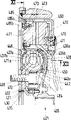
图1是本发明转矩传递装置的剖面图,Fig. 1 is a sectional view of the torque transmission device of the present invention,
图2是从图1中的箭头II的方向上看本发明所述转矩传递装置的局部视图,Fig. 2 is a partial view of the torque transmission device of the present invention from the direction of arrow II in Fig. 1,
图3是一种可能的弹簧结构正面图,Figure 3 is a front view of a possible spring structure,
图4是摩擦装置配置的局部剖面图,Fig. 4 is a partial cross-sectional view of a friction device configuration,
图5是根据图4所示摩擦装置另一个实施例中的摩擦垫,Fig. 5 is a friction pad according to another embodiment of the friction device shown in Fig. 4,
图6-8是根据本发明另一种结构的转矩传递装置的剖面图或局部剖面图,6-8 are sectional views or partial sectional views of a torque transmission device according to another structure of the present invention,
图9是从图8中的箭头IX方向上看的局部简化视图,Figure 9 is a partial simplified view from the direction of arrow IX in Figure 8,
图10是按照本发明另一种结构的转矩传递装置的局部剖视图,Fig. 10 is a partial sectional view of a torque transmission device according to another structure of the present invention,
图11是从图10中箭头XI方向看的局部剖面图,Fig. 11 is a partial sectional view seen from arrow XI direction in Fig. 10,
图12是从图10中箭头XII方向看的局部剖面图,Fig. 12 is a partial sectional view seen from the direction of arrow XII in Fig. 10,
图13和14是按照本发明另一种结构的转矩传递装置的局部剖视图。13 and 14 are partial sectional views of a torque transmitting device according to another structure of the present invention.
图1表示一个分开的飞轮1,该飞轮具有一个可固定在未示出的内燃机曲轴上的第一或初级飞轮质量2以及一个第二或次级飞轮质量3。在将离合器盘5中间安置的情况下,使一个摩擦离合器4固定在第二飞轮质量3上,通过该摩擦离合器4可连接和分离一个同样未示出的传动机构。在此将离合器盘5描述成刚性的实施结构而且仅仅是作为一个例子。该离合器盘5还可以包括其它的结构形式,例如包括摩擦元件和/或减振元件以及配置垫簧。FIG. 1 shows a separate flywheel 1 with a first or primary flywheel mass 2 and a second or secondary flywheel mass 3 which can be fastened to the crankshaft of an internal combustion engine (not shown). With the interposed clutch disc 5 , a friction clutch 4 is fastened to the second flywheel mass 3 , via which friction clutch 4 a transmission, also not shown, can be connected and disconnected. The clutch disk 5 is described here as a rigid embodiment and only as an example. The clutch disc 5 may also include other structural forms, such as including friction elements and/or damping elements and configuring washer springs.
在这种情况下,飞轮质量2和3通过对与它们固定连接的构件进行的中间连接和通过支承装置6彼此作可转动地支承,在该实施例中,将支承6设置在安装第一飞轮质量2或者整个转矩传递装置1到内燃机从动轴上时用于固定螺钉8穿过的通孔7的径向内侧。在此所述的单排滚珠轴承6具有一个带润滑剂储藏室的密封盖6a,而且密封盖6a同时还用于隔热,它使从第二飞轮质量3传至支承6的热量减小或者是避免热传递。在飞轮质量2和3之间作用着一个减振装置9,该装置构成一个环形空间11,环形空间形成近似环面形的区域12。此处所用和所示的螺旋压簧10也可以用其它合适的力储存部件代替,例如用碟形弹簧代替。同时至少要在环形空间11的局部上填充干式润滑剂,例如石墨粉或类似物,或者是软膏状的粘性介质,例如油或油脂。In this case, the flywheel masses 2 and 3 are rotatably supported on each other by means of an intermediate connection of the components fixedly connected to them and by means of a bearing 6 which, in this embodiment, is arranged at the mounting point of the first flywheel The radial inner side of the through hole 7 through which the fixing screw 8 passes when the mass 2 or the entire torque transmission device 1 is attached to the driven shaft of the internal combustion engine. The single-row ball bearing 6 described here has a sealing cover 6a with a lubricant storage chamber, and the sealing cover 6a is also used for heat insulation, which reduces the heat transfer from the second flywheel mass 3 to the bearing 6 or is to avoid heat transfer. Acting between the flywheel masses 2 and 3 is a damping device 9 which forms an annular space 11 which forms an approximately torus-shaped region 12 . The helical compression spring 10 used and shown here can also be replaced by other suitable force storage elements, for example disk springs. At the same time, at least part of the annular space 11 must be filled with a dry lubricant, such as graphite powder or the like, or an ointment-like viscous medium, such as oil or grease.
初级飞轮质量2上具有构件13,该构件最好可用金属薄板制作或拉伸制成,同时该构件13还用于将第一飞轮质量2或整个的分开式飞轮1固定到内燃机从动轴或是与该轴相连的轴上。构件13具有基本上敞开设置的法兰区14,该法兰区支承着径向内侧的法兰15。法兰15的径向延伸区15a上具有与槽7对中的用于固定螺钉8的通孔或开口。单排滚动轴承6的内环16套在法兰15轴向端部的外表面或支承台肩上。在支承6的滚动轴承的外环17上支承着第二飞轮质量3。On the primary flywheel mass 2 there is a member 13, preferably fabricated or drawn from sheet metal, which also serves to fix the first flywheel mass 2 or the entire split flywheel 1 to the driven shaft or is on the axis connected to this axis. The component 13 has a substantially open flange region 14 which supports a radially inner flange 15 . The radial extension 15 a of the flange 15 has through-holes or openings for the fastening screws 8 aligned with the grooves 7 . The inner ring 16 of the single row rolling bearing 6 is sleeved on the outer surface of the axial end of the flange 15 or the supporting shoulder. The second freewheel mass 3 is supported on the outer ring 17 of the rolling bearing of the support 6 .
基本上呈径向布置的区域14径向向外过渡到轴向上朝内燃机一侧的盆形区18,该盆形区又径向向外过渡到一个在轴向远离内燃机一定间距而径向延伸的区域,该延伸区构成了起动齿轮19。为了形成起动齿轮19而使处于板体13径向外侧区域的材料变形和将其折叠,以便使其再次向内弯曲构成翼缘20,该翼缘的壁紧贴在板体13径向外侧的端部上。起动齿轮19的成型或成形可以在将板体折叠之后在板型件中加工形成。这些型廓可以通过切削加工,例如铣或拉削而形成。起动齿轮19的成型还可以通过冲制、亦即通过材料的蠕变过程而构成。此外这种型廓还可以通过冲锻来生产。另一种可以生产这种型廓的手段是,借助高能射线例如激光射束进行切割。比较有利的是,至少在起动齿轮19的造型或成齿区域中,相应的板型件具有比其它区域大的硬度。这种部分或局部硬度的增加可以例如通过感应硬化处理或表面硬化处理实现的。The substantially radially arranged region 14 transitions radially outwards into a cup-shaped region 18 axially facing the internal combustion engine, which in turn transitions radially outwards into a radial region at a distance from the internal combustion engine in the axial direction. An area of extension which forms the starter gear 19 . In order to form the starter gear 19, the material in the radially outer region of the plate body 13 is deformed and folded so that it is again bent inwardly to form a flange 20 whose walls rest against the radially outer side of the plate body 13. on the end. The shaping or shaping of the starter gear 19 can be machined into the plate-shaped part after the plate body has been folded. These profiles can be produced by machining operations such as milling or broaching. The shaping of the starter gear 19 can also be formed by stamping, that is to say by a creeping process of the material. In addition, such profiles can also be produced by stamping. Another way in which such profiles can be produced is by cutting with high-energy radiation, for example a laser beam. It is advantageous if at least in the profiled or toothed region of the starter gear 19 the corresponding plate-shaped part has a greater hardness than in other regions. This partial or local increase in hardness can be achieved, for example, by induction hardening or surface hardening.
为了增大围绕其转轴转动的双质量飞轮1的惯性力矩,可与内燃机连接的初级飞轮质量2上具有一个质量环21。质量环21是由一个板体构成的,它具有两个轴向形式的翼缘22和23以及两个径向形式的翼缘24和25,由此使质量环21形成一个约成L形的截面。质量环21作为板体折叠件是通过将原始的板坯折叠而成的,例如象德国专利申请P4315209所描述的那样,其明显与起动点轮19有关而且就这一点来说它的内容至少是本申请的一个组成部分。In order to increase the moment of inertia of the dual-mass flywheel 1 rotating about its axis of rotation, the primary flywheel mass 2 , which can be connected to the internal combustion engine, has a mass ring 21 . The mass ring 21 is composed of a plate body, which has two axial flanges 22 and 23 and two radial flanges 24 and 25, thereby making the mass ring 21 form an approximately L-shaped section. The mass ring 21 is formed as a panel fold by folding the original blank, for example as described in German patent application P4315209, which is clearly related to the starting point wheel 19 and in this regard its content is at least an integral part of this application.
在目前描述的实施例中,两个轴向延伸的翼缘22和23在径向上彼此直接贴紧。此外,径向外侧的翼缘22设置成比径向内侧的翼缘23短而且翼缘22以其径向延伸的端部区22a紧贴在起动齿轮19的轴向延伸翼缘20上。在这样制作质量环21时,其轮廓例如可以与容纳双质量飞轮的外壳尤其是传动装置罩的内包壳轮廓相适应,为的是不会形成接触。为此,在该实施例中,在质量环21上形成一个如截锥形表面结构的平滑部22b。为了设置平滑部22b而被挤掉的材料可用于径向外侧翼缘22的材料厚度的加大。In the presently described embodiment, the two axially extending flanges 22 and 23 lie directly against each other in the radial direction. Furthermore, the radially outer flange 22 is arranged shorter than the radially inner flange 23 and the flange 22 rests with its radially extending end region 22a on the axially extending flange 20 of the starter gear 19 . When the mass ring 21 is produced in this way, its contour can be adapted, for example, to the contour of the housing housing the dual-mass flywheel, in particular the inner casing of the transmission housing, so that no contact is made. For this purpose, in this embodiment, a smooth portion 22b such as a frusto-conical surface structure is formed on the mass ring 21 . The material squeezed out to provide the smooth portion 22 b can be used to increase the material thickness of the radially outer flange 22 .
径向内侧翼缘23朝内燃机指向延伸且在起动齿19的轴向区域中形成折弯或弯曲23a然后过渡到质量环21的径向延伸的翼缘25。质量环21的弯曲部23a和径向延伸翼缘25靠置在第一飞轮质量2的盆形区18的背离内燃机的一侧上。在该接合区的径向内侧,翼缘25具有一个轴向朝第二飞轮质量3偏移的部分25a,该部分的壁紧贴在第二个径向延伸的翼缘24的壁上。翼缘24在径向向外超过区段25a,并终止在与轴向延伸的翼缘23相隔一定径向间距的位置上。在弯曲部23a的区域中质量环21通过多个分布在圆周上且设在凹槽26中的焊接点27与初级飞轮质量2固定连接。The radially inner flange 23 extends in the direction of the internal combustion engine and forms a bend or bend 23 a in the axial region of the starter tooth 19 before transitioning into the radially extending flange 25 of the mass ring 21 . The bend 23 a and the radially extending flange 25 of the mass ring 21 abut against the side of the pot-shaped region 18 of the first flywheel mass 2 facing away from the internal combustion engine. On the radially inner side of this joint region, the flange 25 has a portion 25 a offset axially towards the second flywheel mass 3 , the wall of which bears against the wall of the second radially extending flange 24 . Flange 24 extends radially outward beyond section 25 a and terminates at a radial distance from axially extending flange 23 . In the region of the bend 23 a, the mass ring 21 is fixedly connected to the primary flywheel mass 2 via a plurality of welding points 27 distributed over the circumference and arranged in the grooves 26 .
凸缘15与第一飞轮质量2对中连接。该对中可以通过例如一个对中座28来实现,对中座与板形件13中相应的对中槽配合作用。同样,该对中结构以及必要时将法兰15固定到第一飞轮质量2上,可以通过突起物29来实现,在目前描述的实施例中,突起物29是从背离内燃机的一侧通过应用法兰15的材料变形移位而成。此外,法兰15的径向内侧有一个对中座30,该对中座用于将双质量飞轮1对中地装到例如马达曲轴上。The flange 15 is centrally connected to the first flywheel mass 2 . This centering can be achieved, for example, by means of a centering seat 28 which cooperates with a corresponding centering groove in the plate-shaped part 13 . Likewise, this centering and, if necessary, the fixing of the flange 15 to the first flywheel mass 2 can be achieved by means of protrusions 29 which, in the presently described embodiment, are applied from the side facing away from the internal combustion engine. The material of the flange 15 is deformed and displaced. Furthermore, on the radially inner side of the flange 15 there is a centering seat 30 which is used for centering the dual mass flywheel 1 on, for example, the crankshaft of a motor.
法兰15在其径向延伸区15a的径向外侧首先倾斜地朝离开内燃机侧的方向径向向外延伸,然后紧接着在其径向外侧区又径向延伸。在该径向外侧区域法兰15与第二法兰31固定连接。此处,实现这种固定连接同样应用法兰15的材料以形成连接凸起32。在连接凸起32的径向内侧,法兰31基本上径向往内延伸,同时法兰31上还具有一个远离内燃机的平缓的隆起部33。法兰31在隆起部33的径向内侧过渡为沿轴向朝内燃机延伸的区域31a,区域31a再次转为沿径向往内延伸的区域31b。径向区域31b与法兰15的径向区段15a贴紧而且其上同样具有一个用于使固定螺钉8穿过的通口,其中在径向区31b背离内燃机的一侧上可以构成一个用于固定螺钉8头部的安置结构。The flange 15 first extends radially outward in a radially outer region 15 a of its radial extent 15 a obliquely in the direction away from the internal combustion engine side, and then extends radially again in its radially outer region. In this radially outer region the flange 15 is fixedly connected to the second flange 31 . Here again, the material of the flange 15 is used to form the connection projection 32 for this fixed connection. On the radial inner side of the connecting projection 32, the flange 31 extends substantially radially inwards, and at the same time, the flange 31 also has a gentle bulge 33 away from the internal combustion engine. Radially inside the bead 33 , the flange 31 transitions into a region 31 a extending axially toward the internal combustion engine, which turns again into a region 31 b extending radially inward. The radial region 31b abuts against the radial section 15a of the flange 15 and likewise has a passage opening for the fastening screw 8 to pass through, wherein on the side of the radial region 31b facing away from the internal combustion engine a hole can be formed for In the arrangement structure of fixing screw 8 head.
法兰15和31的径向外部区或隆起部33的区域中设置有适用于螺旋弹簧10形式的储力器进行加载的加载区34和35。如特别是结合图3所能看出的那样,加载区34和35是由径向延伸的托架15C和13C构成的,它们伸入在周向起作用的储力器10之间的中间腔中。此外,特别如图3所示,使用点,也即储力器10开始加载的点对于内外弹簧来说可以设置得相同或不同,也就是说可以分级。除此以外还可以看到,托架31C和15C在轴向上不重叠,也不全等。相反,托架15C、31C以及它们的加载区34、35是这样设置的,即它们分别与其配合作用的储力器10的弹簧端部相适应。In the radially outer regions of the flanges 15 and 31 or in the region of the bead 33 , loading regions 34 and 35 suitable for loading a force store in the form of a helical spring 10 are provided. As can be seen in particular in connection with FIG. 3 , the loading zones 34 and 35 are formed by radially extending brackets 15C and 13C which protrude into intermediate spaces between the force accumulators 10 acting in the circumferential direction. Furthermore, as shown in particular in FIG. 3 , the point of use, ie the point at which the force store 10 begins to be loaded, can be set identically or differently for the inner and outer springs, that is to say can be graded. In addition, it can be seen that the brackets 31C and 15C do not overlap in the axial direction, nor are they congruent. Instead, the brackets 15C, 31C and their loading regions 34 , 35 are arranged in such a way that they are each adapted to the spring end of the force store 10 with which they cooperate.
在所述实施例中与加载区34和35相互作用的弹簧端部仅具有一个切断位置,端部既不靠放在前面的弹簧圈上,在其与弹簧中轴垂直的端部区域上也不作磨削加工。这意味着,储力器10的弹簧绕圈基本上与储力器10内部的任一个其他绕圈相一致,亦即例如和一个螺纹相类似,其实际上具有相同的螺距。由此可以将弹簧端部绕圈作为弹簧圈来使用,这样就省去非弹性的绕圈并因而获得更大的弹簧容量或较小的弹簧体长度。此外,这样设计的弹簧端部具有以下优点,即只需将弹簧丝切断即可,由此省去了否则必需的加工过程,例如将最后一个弹簧绕圈靠置到前一圈上以及将弹簧端部进行磨削以提供一个平坦的安装面。In the embodiment described, the spring ends interacting with the loading zones 34 and 35 have only a cut-off position, neither resting on the front coils nor on their end regions perpendicular to the spring center axis. Grinding is not performed. This means that the spring winding of the force accumulator 10 essentially corresponds to any other winding within the force accumulator 10 , that is to say for example resembles a thread which has practically the same pitch. As a result, the spring end coils can be used as spring coils, so that non-elastic coils are omitted and thus a greater spring volume or a smaller spring body length is obtained. Furthermore, a spring end designed in this way has the advantage that it is only necessary to cut off the spring wire, thereby eliminating the otherwise necessary machining operations, such as placing the last spring coil on the previous coil and attaching the spring coil to the previous coil. The ends are ground to provide a flat mounting surface.
这种与相应的加载区配合使用的弹簧结构并不受所列举的双质量飞轮的实例的限制,它也可用于任何其它的配置上,例如用于阻尼器中。此外,还可以用例如烧结件或锻造件等部件来取代两个法兰15和31,其中加载区34和35同样要与储力器10形成相应配合。The spring configuration used in conjunction with the corresponding loading zone is not restricted to the example of a dual-mass flywheel cited, but it can also be used in any other arrangement, for example in a damper. Furthermore, instead of the two flanges 15 and 31 , parts such as sintered parts or forged parts can also be used, wherein the loading regions 34 and 35 likewise have a corresponding fit with the force store 10 .
还可以这样设置两个法兰15和31或是用于取代它们的烧结件或锻造件,即应使它们在与储力器10相配合的加载区34和35的区域中附带形成用于储力器10的防转装置。这种防转装置的作用是使储力器精确的保持在其原始设置的位置上并精确导行,而且不会出现例如相对弹簧圈轴线的转动。这样设置的优点是,使自由的弹簧端圈总是靠置于加载区34和35的相同位置上并且能够保证,端圈以其完全的弹性能或弹性容量为吸收振动能使用。It is also possible to arrange the two flanges 15 and 31 or to replace them with sintered parts or forged parts, that is, they should be additionally formed in the region of the loading areas 34 and 35 that cooperate with the force accumulator 10 for the accumulator. The anti-rotation device of force device 10. The function of this anti-rotation device is to hold the force store exactly in its original set position and to guide it precisely, and no rotation can occur, for example relative to the axis of the spring coil. This arrangement has the advantage that the free spring end coils always rest on the same position in the loading zones 34 and 35 and ensures that the end coils use their full elastic energy or elastic capacity for absorbing vibration energy.
另一方面,储力器10的内侧弹簧支撑在加载区36a和37a上而外侧弹簧支撑在加载区36b和37b上。从圆周方向观察,加载区37a、b和36a、b不仅可以设在同样的高度上而且可以错位设置。这样同样可以实现储力器加载端(开始)的固定。储力器加载区36a、b设置在第一薄板38上,该薄板的径向内侧支撑在支承6或在此为单排滚柱轴承6的轴承外环17上,而其径向外侧则支撑在第二飞轮质量3上。On the other hand, the inner spring of the accumulator 10 is supported on the loading areas 36a and 37a and the outer spring is supported on the loading areas 36b and 37b. Seen in the circumferential direction, the loading zones 37a, b and 36a, b can be arranged not only at the same height but also offset. The fixing of the loading end (beginning) of the force accumulator can also be realized like this. The accumulator loading areas 36 a, b are arranged on a first sheet 38 which bears on the radially inner side on the bearing 6 or, here, the bearing outer ring 17 of the single-row roller bearing 6 , and on its radially outer side On the second flywheel mass 3.
在此,薄板38在其径向内侧区域中带有一个朝着马达延伸的凸肩39,凸肩39具有这样的内径,它能使带密封盖6a的轴承外环17置入其中。在与内燃机侧相反的一侧上,这个凸肩上具有一个缩小的直径40,该直径在薄板38和滚动轴承6之间起轴向限位或轴向固定的作用。从缩小的截面40向外,薄板38朝背离内燃机的方向倾斜的径向向外延伸,该延伸区段41基本上是直线延伸的。In this case, the sheet metal 38 has, in its radially inner region, a shoulder 39 extending towards the motor, the shoulder 39 having an inner diameter such that the bearing outer ring 17 with the sealing cover 6a can be inserted therein. On the side opposite the internal combustion engine side, this shoulder has a reduced diameter 40 which acts as an axial stop or fixation between the sheet metal 38 and the rolling bearing 6 . From the reduced cross-section 40 outwards, the sheet metal 38 extends obliquely radially outwards away from the internal combustion engine, the extension 41 extending substantially in a straight line.
直线段41含有一个贯穿的通口42,该通口适合于容置固定螺钉8的螺钉头部并由此使固定螺钉8在转矩传递装置1没有固定或安装的状态下固定在与双质量飞轮1的转轴基本同轴的位置上。直线薄板段41的径向外侧过渡到圆弧形截面区43,该区域至少基本上与储力器10的外轮廓相匹配并至少局部地在轴向和径向包住它(10)。在区域43朝内燃机指向的自由端部上接续一个径向往外伸出的径向段44,该区段44与第二薄板46的径向区段45固定连接,薄板46在轴向上设置在薄板38和板件13之间。两个薄板38和46的连接借助于O型圈47相对径向外边进行密封。The straight section 41 contains a through opening 42, which is suitable for accommodating the screw head of the fixing screw 8 and thereby fixing the fixing screw 8 in a state with the double mass when the torque transmission device 1 is not fixed or installed. The rotating shaft of flywheel 1 is basically on the coaxial position. The radially outer side of the straight sheet metal section 41 merges into a circular arc-shaped cross-sectional area 43 which at least substantially matches the outer contour of the force store 10 and encloses it ( 10 ) at least partially axially and radially. On the free end of the region 43 pointing towards the internal combustion engine there follows a radial section 44 projecting radially outwards, which section 44 is fixedly connected to a radial section 45 of a second sheet metal 46 which is arranged axially at Between the thin plate 38 and the plate 13 . The connection of the two thin plates 38 and 46 is sealed against the radial outer edge by means of an O-ring 47 .
薄板46以其径向区段45的径向内侧局部包围O型圈47并且以其轴向背离内燃机侧延伸的部分区域轴向插入由薄板38包围的空间中。这样即可保证环形腔11或空间12的密封并同时使薄板38和46相互对中。由此起薄板46基本上是径向往内延伸的,而且该部分基本上与储力器10的外轮廓相匹配,并在第一飞轮质量2的板件13和法兰15之间的轴向结构空间中延伸。The radial inner portion of the thin plate 46 partially surrounds the O-ring 47 with its radial section 45 and inserts axially with its partial region extending axially away from the internal combustion engine side into the space enclosed by the thin plate 38 . This ensures the sealing of the annular space 11 or the space 12 and at the same time centers the lamellae 38 and 46 relative to each other. As a result, the thin plate 46 extends substantially radially inwards, and this portion substantially matches the outer contour of the force accumulator 10 , in the axial direction between the plate 13 of the first flywheel mass 2 and the flange 15 . extended in structural space.
薄板46在加载区37a和37b的径向内侧具有一个在轴向上朝内燃机倾斜的区域48,该区域48靠置在碟簧49上,碟簧的径向内侧与法兰15形成接触并由此对空腔11构成径向内侧方向的密封。因此,碟簧49既可以在薄板46的区域中对中也可以在法兰15上对中。另一种碟簧50用于在法兰31和薄板38之间相对径向内侧对空腔11形成密封。在此,碟簧50的外径靠置在法兰31的隆起处33而叠簧50的内径则在法兰31的轴向延伸区段31a的区域中与薄板38靠紧。为了使碟簧50对中,在薄板38上设置了多个沿四周分布的对中突起51,这些突起是通过使法兰38的材料局部变形而形成的。也可以设置环形封闭的突起或使碟簧50相应地与法兰31对中来代替在周向上分布的多个对中突起。On the radially inner side of the loading zones 37a and 37b, the thin plate 46 has an area 48 inclined axially towards the internal combustion engine, which rests on a disc spring 49 whose radially inner side comes into contact with the flange 15 and is held by the The pair of cavities 11 form a seal in the radially inner direction. The disk spring 49 can thus be centered both in the region of the sheet metal 46 and on the flange 15 . A further disc spring 50 is used to seal the cavity 11 between the flange 31 and the thin plate 38 relative to the radial inside. In this case, the outer diameter of the disc spring 50 rests against the bead 33 of the flange 31 , while the inner diameter of the ring spring 50 abuts against the sheet metal 38 in the region of the axial extension 31 a of the flange 31 . For centering the disk spring 50 , a plurality of centering projections 51 distributed around the circumference are provided on the sheet metal 38 , and these projections are formed by locally deforming the material of the flange 38 . Instead of several centering projections distributed in the circumferential direction, it is also possible to provide annular closed projections or to center the disk spring 50 accordingly with the flange 31 .
在外径区中,薄板38和46以其径向区44和45支撑第二飞轮质量3。为此将径向区44和45设置在第二飞轮质量3上背离摩擦面的一侧上,以便当可能出现不密封时或是当密封圈47失灵时可以使包含在空腔11中的介质或润滑剂导向第一飞轮质量2去,这样就不会对离合器盘5的摩擦垫的摩擦效果造成影响,从而使摩擦离合器4能够继续传递全部的转矩。在该实施例中,与第二飞轮质量3的连接是通过卷边板52来实现的,该卷边板52上径向向外延伸的连接部分53在摩擦面一侧紧靠在第二飞轮质量3上,并将其在径向内侧最大部分地覆盖住,而且,通过径向区44和45中的开槽轴向穿出。此外,卷边板52具有朝向内燃机一侧的舌部54,舌部在安装状态下同样地径向往外延伸,由此可将两个薄板38和46固定到飞轮质量3上。舌部54最初状态朝内燃机的轴向延伸而在第二飞轮质量3、卷边板52和薄板38和45定位和安装之后则产生这样的塑性变形,即如图1所示,径向向外延伸。In the outer diameter region, the thin plates 38 and 46 support the second flywheel mass 3 with their radial regions 44 and 45 . For this purpose, the radial regions 44 and 45 are arranged on the side of the second flywheel mass 3 facing away from the friction surface, so that the medium contained in the cavity 11 can be kept free in the event of possible leaks or when the sealing ring 47 fails. Or the lubricant is guided to the first flywheel mass 2, so that it will not affect the friction effect of the friction pad of the clutch disc 5, so that the friction clutch 4 can continue to transmit all the torque. In this embodiment, the connection with the second flywheel mass 3 is realized through the curling plate 52, and the radially outwardly extending connecting portion 53 on the curling plate 52 abuts against the second flywheel on the side of the friction surface. Mass 3 and covers it to the greatest extent on the radially inner side and axially protrudes through the slots in the radial regions 44 and 45 . Furthermore, the flange 52 has a tongue 54 facing the internal combustion engine, which likewise extends radially outward in the installed state, whereby the two laminations 38 and 46 can be fastened to the flywheel mass 3 . The tongue 54 initially extends in the axial direction of the internal combustion engine and after positioning and installation of the second flywheel mass 3, the bead plate 52 and the thin plates 38 and 45 is plastically deformed such that, as shown in FIG. 1 , radially outward extend.
与由离合器4和离合器盘5构成的离合器装置合在一起,双质量飞轮1构成了一个结构单元,它作为一个预安装单元;运输,储存,然后可以用非常简单和合理的方式装到内燃机的曲轴上,通过这种设置可以省去多个不同的工序,例如否则所需的离合器盘对中过程;离合器盘的装入、离合器的安装、导入对中心轴、离合器盘的自身对中、以及螺钉的插入、用螺丝将离合器旋紧以及取出对中心轴等工序。Together with the clutch arrangement consisting of the clutch 4 and the clutch disc 5, the dual mass flywheel 1 constitutes a structural unit which, as a pre-assembled unit; On the crankshaft, a number of different processes can be omitted by this arrangement, such as the otherwise required centering of the clutch disc; insertion of the clutch disc, installation of the clutch, introduction of the centering shaft, centering of the clutch disc itself, and Inserting the screw, tightening the clutch with the screw, taking out and aligning the central shaft, etc.
可以将固定螺钉8预安装或保持在凸缘区14和法兰15的孔中,同时将它以合适的方式保持在不会丢失的位置上,例如用柔性部件,这些部件是这样确定的,即在拧紧螺钉8时能克服这些部件的保持力。The fixing screw 8 can be pre-installed or held in the holes of the flange area 14 and the flange 15, while it is held in a suitable manner in a position that cannot be lost, for example with flexible parts, these parts are determined in this way, That is, the holding force of these parts can be overcome when the screw 8 is tightened.
离合器盘5被夹紧在压板55和第二飞轮质量3的摩擦面之间且相对于单元转轴预对中的位置上,同时离合器盘5上设置的开口56处于这样一个安装位置,即当将离合器装置或结构单元固定到内燃机的从动轴上时螺纹工具能作贯穿运动。此外,如图示实施例所述的那样,开口56可以比螺钉8的头小,以便由此确保无可指摘的和不会丢失的将螺钉8保持在装置的内部。The clutch disc 5 is clamped between the pressure plate 55 and the friction surface of the second flywheel mass 3 in a pre-centered position relative to the unit shaft, while the opening 56 provided on the clutch disc 5 is in a mounting position such that when the The threaded tool can perform a penetrating movement when the clutch device or the structural unit is fixed to the driven shaft of the internal combustion engine. Furthermore, as in the illustrated embodiment, the opening 56 may be smaller than the head of the screw 8, in order thereby to ensure an impeccable and non-lost retention of the screw 8 inside the device.
在碟簧57的舌部区57a上也设置了用于使螺纹工具穿过的通孔或开口,然而这在图中没有详细表示。此外这些开口也可以用加宽或拓宽的缝来构成,这些缝在舌部57a之间形成。碟簧57上的开口与离合器盘5上的开口56在轴向上相互重叠而且通过它们的轴向对准结构,可以允许安装工具通过以拧紧螺钉8和将装置固定到内燃机曲轴上。Through-holes or openings for the passage of a threading tool are also provided on the
通过碟簧57进行操作的摩擦离合器4在其离合器盖体60上具有一个一方面处于盖体60一侧的回转支承58,和另一方面处于远离盖体60一侧的回转支承59。这些由钢丝环构成的回转支承58和59由在圆周上分布的夹板61保持。夹板61与盖体60做成一体并通过其材料适当变形而构成。在背离盖体60的一侧上夹板61至少部分地在轴向和径向上包围住回转支承59。回转支承58的固定可以通过将位于回转支承58径向外侧的盖体60压制成凹缘62来保证。也可以通过设置多个周向分布的分段凹缘来代替连续的封闭式凹缘62。如图中所示,压板55至少在夹板61的区域内与夹板的轮廓相匹配,而在其它区域则与回转支承59的轮廓相匹配。然而也可以和所描述的实例有所不同,使之与夹板61的匹配在整个周向区上保持不变。The friction clutch 4 , which is actuated by means of a disk spring 57 , has on its clutch cover 60 a pivot bearing 58 on the side of the cover 60 on the one hand and a pivot bearing 59 on the side remote from the cover 60 on the other hand. These slewing bearings 58 and 59 , which consist of wire rings, are held by clamping plates 61 distributed over the circumference. The splint 61 is integrally formed with the cover body 60 and is formed by proper deformation of its material. On the side facing away from the cover 60 , the clamping plate 61 surrounds the swivel bearing 59 at least partially axially and radially. The fixing of the slewing bearing 58 can be ensured by pressing the cover body 60 located on the radially outer side of the slewing bearing 58 into a concave edge 62 . Instead of the continuous closed bead 62 , it is also possible to provide a plurality of segmented bezels distributed in the circumferential direction. As shown in the figure, the pressure plate 55 is adapted to the contour of the clamping plate at least in the region of the clamping plate 61 and to the contour of the swivel bearing 59 in other regions. However, deviating from the example described, it is also possible for the adaptation to the clamping plate 61 to remain constant over the entire circumferential area.
为了进行转矩传递和使压板55作离开运动而设置了板簧件63,如图2所示,该板簧件一方面通过铆钉64与外壳或盖体60相连,另一方面通过铆钉65与压板55相连,在该实施例中,与压板55的铆接发生在径向向内突出的压板凸起66的区域中,这些凸起66安置在离合器盘5的摩擦垫的径向内侧。压板凸起66从开口67的区域中轴向穿过碟簧57,以使将板簧件63安装到盖体60上背离压板55的一侧上。这种板簧结构在使用时不受分开式飞轮的限制,它可普遍用于例如和一个传统的飞轮结构的其它结构的离合器类型中。如特别是从图2中所能看到的那样,所需的开口67可以通过从碟簧舌部57a上去掉一部分或是通过将碟簧舌部57a完全去掉而形成。碟簧舌部57a与离合器盘5的承载板轮廓相配合并且在此处所描述的压缩式离合器结构类型且在摩擦离合器4的分离位置上碟簧舌部至少基本上与承载板平行延伸。In order to carry out torque transmission and make the pressure plate 55 move away, a leaf spring 63 is provided, as shown in Figure 2, the leaf spring is connected with the shell or cover 60 by
除了在离合器盘5中的薄板38和56上所设的开口42之外还进一步设置了用于冷却整个装置的并处于离合器盖体60区域上的开口或通道68和69、处于离合器盘5上的5a、处于第二飞轮质量3上的70和处于第一飞轮质量2的板件13上的71。通过使整个装置获得足够的冷却可以进一步防止,保持在环形区12中的膏状介质如油脂出现不允许的变热,因变热会引起介质粘度下降以至熔化。此外增加热载荷会对结构单元的整体寿命产生不利影响。为了进一步改善散热效果可以在第二飞轮质量3(72处)和/或在压板55上设置一个增大的表面,同时这种表面可以通过将所述通道设置成鼓风机叶片来构成。In addition to the openings 42 provided on the sheets 38 and 56 in the clutch disc 5 there are further openings or channels 68 and 69 for cooling the entire device in the area of the clutch cover 60 , on the clutch disc 5 5a, 70 on the second flywheel mass 3 and 71 on the plate 13 of the first flywheel mass 2. Sufficient cooling of the entire device further prevents an impermissible heating of the pasty medium, such as grease, held in the annular region 12 , which would cause the medium to lose its viscosity and thus melt. Furthermore, increased thermal loads can adversely affect the overall lifetime of the structural element. In order to further improve the cooling effect, an enlarged surface can be provided on the second flywheel mass 3 (at 72 ) and/or on the pressure plate 55 , while this surface can be formed by arranging the channels as blower blades.
与第二飞轮质量3固定连接的离合器盖体60主要由基本上呈空心圆柱形的轴向区域73和至少基本上径向延伸部分74构成,区域74中可回转地支承着碟簧57。轴向区域73在轴向上越过第二飞轮质量3,而且还可以通过销钉连接或借助于焊接与之在轴向上以及在转动方向上形成固定联接。其它可能的连接类型由例如DE-OS4117584给出。The clutch cover 60 , which is fixedly connected to the second flywheel mass 3 , essentially consists of a substantially hollow-cylindrical axial region 73 and an at least substantially radial extension 74 , in which the disk spring 57 is rotatably mounted. The axial region 73 extends beyond the second flywheel mass 3 in the axial direction and can also be fixedly coupled thereto in the axial direction and in the rotational direction by means of a pin connection or by means of welding. Other possible connection types are given eg by DE-OS4117584.
轴向区域73的一部分或沿轴向指向的舌部75沿轴向通过第二飞轮质量3朝着内燃机的方向延伸。舌部75的轴向端部区伸到这样一个轴向区,该区域的径向内侧受惯性体或质量环21的径向区24的限制而该区域的径向外侧受惯性体或质量环21的轴向区23的限制。在这个由质量环21包围的空间中设有摩擦装置76,该摩擦装置可以通过轴向舌75进行控制。摩擦装置76包含至少一个例如如图5所示的摩擦垫77。摩擦垫77由基本上与安装空间或安装半径相匹配的塑料件78以及一个或多个储力器79构成,储力器79能使塑料件78在径向上伸展。摩擦垫77在轴向上是这样固定的,即它的径向内侧有一个锁定轮廓80,该轮廓与质量环21配合作用。在此处所描述的实施例中,锁定轮廓80由一个锥形表面构成,锥形的尖朝向内燃机方向,该锥形尖伸到一个相应后边面的后边,并抓住径向区24上的同样锥形面。A part of the axial region 73 or an axially directed tongue 75 extends axially through the second flywheel mass 3 in the direction of the internal combustion engine. The axial end region of the tongue 75 extends into an axial region whose radially inner side is bounded by the radial region 24 of the inertial body or mass ring 21 and whose radially outer side is bounded by the inertial body or mass ring 21 is limited by the axial zone 23. In this space enclosed by the mass ring 21 there is a friction device 76 which can be actuated via the axial tongue 75 . The friction means 76 comprise at least one
图4中所示的摩擦垫177具有另一种与摩擦垫77不同的结构。在此是这样将一个最初平坦的塑料件178施加径向预应力的,即,将预先平整的塑料件178与起板簧作用的且同样最初是直线的圆钢丝179一起变形地装入弯曲的并由质量环21围成的空间中。此外从图4中还能看到,轴向舌部75可以相对摩擦垫77或177之间具有间距81,由此可以在出现使间隙或距离81消失的转角之后才产生摩擦作用。在多个周向分布的摩擦垫77或177情况下还可以使这些间距设置成不同的方式,以便产生分级的摩擦效果。例如摩擦垫77或177也可以无间隙地安置在各轴向舌部75之间。同样,也可以这样来分配或调整摩擦力,即用不同的材料构成摩擦垫77、177或是对摩擦垫77、177施加不同的径向预应力。The friction pad 177 shown in FIG. 4 has another structure different from the
图6中所表示的部件与迄今为止所描述的部件相近或相等,其所用标号与原始标号相似但比原始标号高出100。Components shown in Fig. 6 which are similar or equivalent to those hitherto described have been given reference numbers which are similar to but 100 higher than the original reference numbers.
该分开的飞轮101基本上与迄今所描述的双质量飞轮1的结构相一致,所不同的是具有一个替代滚动轴承6的滑动轴承106。为了形成滑动轴承106的位置,在法兰115的轴向端部115b处的外周表面或支撑凸肩上置有塑料套筒106b形状的滑动轴承材料。轴承套筒106b从与径向向内伸出的卷边106C相贴紧的轴向端部115b的自由端开始,首先朝着内燃机的方向延伸,然后形成一个弯曲并转入径向向外伸出的区域106d,该区域106d紧靠在法兰115的支撑区115d上。轴向上朝马达延伸的且以其内圆周包围轴承套筒106b的薄板138的凸肩139以其朝向内燃机一侧的自由端139a与轴承套筒106b的延伸端或径向向外的伸出部分106d相配合。通过这种设置可以确保,薄板138以及借助该薄板使第二飞轮质量103与固定在其上的离合器104一起既在径向上得以支承又至少在一个轴向上得以支承。与所述实施例不同,还可以将径向施力部件和轴向施力部件的支撑结构设置成分离的轴承套筒件。The separate flywheel 101 basically corresponds to the structure of the dual-mass flywheel 1 described so far, with the difference that a slide bearing 106 is present instead of the rolling bearing 6 . In order to form the location of the slide bearing 106 , a slide bearing material in the form of a plastic sleeve 106 b is placed on the outer peripheral surface or support shoulder at the axial end 115 b of the flange 115 . The bearing sleeve 106b starts from the free end of the axial end portion 115b abutting against the radially inwardly protruding bead 106c, first extends in the direction of the internal combustion engine, then forms a bend and turns into a radially outwardly protruding Out of the area 106d, the area 106d is in close contact with the support area 115d of the flange 115. The shoulder 139 of the thin plate 138 which extends axially towards the motor and surrounds the bearing sleeve 106b with its inner circumference, with its free end 139a facing the internal combustion engine side and the extended end of the bearing sleeve 106b or the radially outward projection Part 106d cooperates. This arrangement ensures that the thin plate 138 and with it the second flywheel mass 103 together with the coupling 104 fastened thereto is supported both radially and at least in one axial direction. Different from the described embodiment, it is also possible to arrange the supporting structure of the radial force application part and the axial force application part as a separate bearing sleeve part.
离合器盘105的支承板与盘的轮毂或轮毂凸缘的连接在此不象附图1所述实施例那样通过铆钉实现,而是通过摩擦焊接105b来形成的。此外这种连接还可以通过利用轮毂凸缘的材料来实现,这样同样不需要附加连接部件。这种连接是以非常经济的方式亦即很少的部件成本来生产的。The connection of the bearing plate of the clutch disc 105 to the hub or the hub flange of the disc is not realized here by means of rivets, as in the embodiment described in FIG. 1, but by friction welding 105b. Furthermore, this connection can also be realized by using the material of the hub flange, so that no additional connecting parts are likewise required. Such connections are produced in a very economical manner, ie with little component cost.
图6a表示支撑板与离合器盘105的轮毂或轮毂凸缘之间的另一种连接形式105C。在此将支撑板在通孔156的区域中进行这样的变形,即在利用离合器支撑板的材料变形情况下使之与轮毂凸缘构成铆接。这里,离合器盘105的支撑板材料轴向贯穿轮毂凸缘而且在轴向穿越之后,相对通孔156上径向往外变形,从而构成一种使离合器盘105的支撑板和轮毂凸缘固定连接的后边缘。通过这种方式可以用很少的部件形成耐久的连接。由于较大的铆接圆孔和铆接直径可能会降低支撑板的强度。FIG. 6 a shows another form of connection 105C between the support plate and the hub or hub flange of the clutch disc 105 . In this case, the support plate is deformed in the region of the through-opening 156 in such a way that it forms a riveted joint with the hub flange while deforming the material of the clutch support plate. Here, the material of the supporting plate of the clutch disc 105 axially passes through the hub flange and after the axial crossing, it deforms radially outward relative to the through hole 156, thereby forming a fixed connection between the supporting plate of the clutch disc 105 and the hub flange. rear edge. In this way durable connections can be formed with few components. The strength of the support plate may be reduced due to larger riveting holes and riveting diameters.
图7表示另一个实施例,其中对于相同或类似的部件用类似的标号表示,但比原标号数大100。Fig. 7 shows another embodiment in which like reference numerals are used for the same or similar parts, but are 100 greater than the original reference numerals.
此处所示的双质量飞轮201与图1所示实施例的不同主要在于第二飞轮质量203与薄板246之间的连接。薄板246具有一个加长的径向区245,该区域在径向上覆盖住第二飞轮质量203,而且该区域在径向外侧端部过渡为背离内燃机方向伸展的轴向区245a。借助该轴向区245a可以使薄板246在轴向上至少局部覆盖第二飞轮质量203,而且可以用销钉将该区域和第二飞轮质量以及离合器盖体260的轴向分布区273固定连接在一起。在第二飞轮质量203的径向内侧区域中,薄板246通过首先在背离内燃机的方向上轴向伸出的舌部246a与薄板238固定连接,舌部246a轴向穿过薄板238的径向区244并且在这些部件装配之后塑性地这样变形,即它在第二飞轮质量203的侧面上径向向内延展。该舌部246a是直接用薄板246的材料制成的,因此可以省去一个附加的与图1中的卷边钢板52相类似的卷边钢板。这种结构的另一个优点是,减小了从第二飞轮质量203到两个薄板238和246上的热传递和由此形成的对润滑剂的直接作用。此外,特别是在所述薄板246的径向区245上采用了用于冷却的附加开口245b。The
在该实施例中设置有适合于摩擦装置276的摩擦垫177,摩擦垫177的实施结构已在图4中描述而且它借助于锁定轮廓180在后边卡住质量环221的翼缘224。在这种实例的摩擦垫177上,翼缘224的径向外侧限界面可以保持轴线平行,由此可以省掉图1中生产锥形结构的工序并因而能够实现经济地生产。In this exemplary embodiment, a friction pad 177 is provided for the
图8表示本发明所述转矩传递装置的另一个实施例,其中对相似或相同的部件使用比以上标号再加100的标号。Fig. 8 shows another embodiment of the torque transmitting device according to the present invention, wherein like or identical parts are numbered by adding 100 to the above numbers.
与图1所示双质量飞轮1不同的是,分开的飞轮301上具有一个呈S形截面的质量环321,其中该环中容纳一个由其包围的摩擦装置376。摩擦装置376在功能、配置方式及结构方面基本上与迄今所描述的摩擦装置相一致。In contrast to the dual-mass flywheel 1 shown in FIG. 1 , the split flywheel 301 has a mass ring 321 with an S-shaped cross-section, wherein a friction device 376 surrounded by it is accommodated in the ring. The friction device 376 basically corresponds to the friction device described so far in terms of function, configuration and structure.
与迄今为止所述的转矩传递装置不同,双质量飞轮301具有一个转矩限制机构或滑动离合器381,该限制机构有效地设置在第二飞轮质量303和构成空腔311的薄板338、346之间。第二飞轮质量303与薄板338和346的连接是通过卷边板352以与图1所示相类似的方式实现的。在第二飞轮质量303和卷边板352或薄板338之间安置摩擦垫形式的摩擦材料382。该摩擦垫同时也在朝着含有润滑剂的空腔311的方向上起隔热作用。在薄板346上朝着板件313一侧的径向区345和卷边板352的变形保持舌部354之间设有一个碟簧383,该碟簧产生轴向力,该轴向力使第二飞轮质量303、卷边板352和径向区344和345相互张紧,由此可以依据在摩擦垫382上出现的摩擦来传递一个确定的转矩或传递由滑动离合器381或依此由分离的飞轮301在周向上产生的一个确定的力。Unlike the torque transfer devices described so far, the dual mass flywheel 301 has a torque limiting mechanism or slip clutch 381 operatively disposed between the second flywheel mass 303 and the thin plates 338, 346 forming the cavity 311 between. The connection of the second flywheel mass 303 to the sheets 338 and 346 is achieved by means of a beading plate 352 in a manner similar to that shown in FIG. 1 . A friction material 382 in the form of a friction pad is arranged between the second flywheel mass 303 and the flange 352 or the sheet metal 338 . At the same time, the friction pad acts as a thermal insulation in the direction of the lubricant-containing cavity 311 . A disc spring 383 is arranged between the radial zone 345 on the side of the plate 313 on the thin plate 346 and the deformation holding tongue 354 of the curling plate 352, and the disc spring generates an axial force, which makes the first The two flywheel masses 303, the beading plate 352 and the radial regions 344 and 345 are tensioned against each other, so that a certain torque can be transmitted depending on the friction that occurs on the friction pad 382 or transmitted by the slip clutch 381 or thereby separated A definite force produced by the flywheel 301 in the circumferential direction.
碟簧383的挤压力和由此可传递的转矩是可以这样影响的,即在第一飞轮质量302与第二飞轮质量303的最大相对转动区域中,可传递的转矩是减小的,为的是第一和第二飞轮质量侧在滑动离合器381至少部分打开时可继续相对转动,从而可以防止其它部件的有害过度力矩或避免有害的过度力矩传递到后接的传动装置。在此特别如从图9中所看到的那样,碟簧383上有一个从它的平面上朝内燃机方向倾斜的翼件383a,翼件383a与板件313上相应构成的上升斜台313a配合作用。The compression force of the disc spring 383 and thus the transmittable torque can be influenced in such a way that the transmittable torque is reduced in the region of maximum relative rotation of the first flywheel mass 302 and the second flywheel mass 303 , in order that the first and second flywheel mass sides can continue to rotate relative to each other when the slip clutch 381 is at least partially opened, thereby preventing harmful excessive torque from other components or preventing harmful excessive torque from being transmitted to the subsequent transmission. Here, as can be seen in particular from FIG. 9 , the disk spring 383 has a wing 383 a inclined from its plane in the direction of the internal combustion engine, which cooperates with a correspondingly formed rising ramp 313 a on the plate 313 effect.
在第一飞轮质量302和第二飞轮质量303彼此相对转动时,舌部383a和上升斜台313a彼此靠近,而且它们在转动一个确定的扭转角之后相互靠置。当在同一方向上继续进行相对转动时,舌部383a在上升斜台313a上滑动并且使碟簧383与第一飞轮质量302的板件313轴向靠近,这样便减小了碟簧力。这种碟簧力的减小会引起滑动离合器381至少部分打开,从而可使第二飞轮质量303与在其上固定的离合器304一起相对于薄板338和346连续滑动。因此滑动离合器381不仅能在一个相对转动的方向上起作用而且还在两个方向上都起作用,而且它在两个相对转动方向上既可以有同样的,即对称的结构也可以有不同的结构。滑动离合器或设置成终端角可控制的转矩限制机构381,在图8所示实施例中在第二侧和径向上(对中地)设置在第二飞轮质量303和储力器301之间。When the first flywheel mass 302 and the second flywheel mass 303 are rotated relative to each other, the tongue 383a and the ramp 313a approach each other, and after a rotation of a defined angle of rotation they rest against each other. As the relative rotation continues in the same direction, the tongue 383a slides on the rising ramp 313a and brings the disc spring 383 axially closer to the plate 313 of the first flywheel mass 302, thus reducing the disc spring force. This reduction in disc spring force causes slip clutch 381 to at least partially open, thereby allowing continuous sliding of second flywheel mass 303 with clutch 304 fixed thereto relative to plates 338 and 346 . Therefore, the sliding clutch 381 can not only work in one direction of relative rotation but also in two directions, and it can have the same, that is, a symmetrical structure and a different structure in two directions of relative rotation. structure. A slipping clutch or a torque limiting mechanism 381 arranged to be controllable in the terminal angle, in the embodiment shown in FIG. .
图10表示的结构基本上与图1所示结构相似,其中对于功能上相等或相似的部件用相似的标号表示,但各标号比前面又增加100。Figure 10 shows a structure substantially similar to the structure shown in Figure 1, wherein similar reference numerals are used for functionally equivalent or similar parts, but each reference number is increased by 100 from the previous ones.
在目前所描述的双质量飞轮401中,法兰415和431在法兰431的总延伸长度上彼此靠紧,它们之间不存在彼此在轴向上隔开的区域。此外第一飞轮质量402的板件413上具有一个用于使第一飞轮质量402或整个双质量飞轮401在内燃机的从动轴上对中的对中支座430。还可以将法兰415和413组装成一个单独的部件,该部件可以制成铸造件、锻造件或烧结件。In the presently described dual
空腔411的径向内侧限界,在该实施例中,是由一个分开的且构成壁部的部件484形成的,该部件在此是由塑料制成的而且它能够附带地以其径向内侧区包围住固定螺钉408的螺钉头和可以适当地设置得,可以引导螺钉408或避免螺钉408产生歪斜。塑料件484在其径向外侧区域中包围住起密封作用的碟簧450,碟簧450另外还与薄板438配合作用。用于使螺纹工具穿过或使固定螺钉408贯穿的开口442是由轴向突起或凸缘442a围成,该突起处的内径适合于在双质量飞轮401没有安装的状态下容纳固定螺钉408,并对其进行支撑和将其保持在至少与转矩传递装置的转轴接近同轴的位置上。在其外周的径向外侧区域中,突起或凸缘442a可以例如形成安装碟簧密封装置450的辅助对中结构。The radial inner limit of the cavity 411 is, in this embodiment, formed by a separate wall-forming
在目前描述的实施例中,第二飞轮质量403借助于多个沿周向分布的固定板485与离合器盖体460的轴向区473相连。如特别是结合图11所看到的那样,固定板485上具有径向突起,该突起通过合适的开口穿过离合器盖体460的径向区473。固定板485借助于螺钉485a拧紧在第二飞轮质量403背离摩擦表面的一侧上,其中还可以通过在第一飞轮402上起通风作用的开口485而到位。因此,可以通过固定板485和第二飞轮质量403之间接触面上的不同造型来形成不同的径向和轴向张紧力。In the presently described exemplary embodiment, the
第一飞轮质量402的板件413还具有其它起通风作用的开口471和471a,其中径向内侧部471a大约设置在空腔411的径向区中。由此可形成一股空气流,该空气流直接流过空腔411并由此避免保存在空腔中的润滑剂出现不允许的过热。此外从图10还可以看出,板件413上背离内燃机的一侧在空腔411的径向区域内至少与空腔的轮廓基本相适应。The
图12以实施例形式表示加载区436a和436b的配置,加载区437b与436a、436b对称设置。同时,加载区436a、436b、437a、437b不用附加单个构件而形成,其中薄板438和446的材料在轴向上产生变形而且这种变形表现为轴向相对指向。为了在周向上实现图12所示的加载区436a和436b的分级,可以通过所谓的双重收缩来形成这种轴向变形。Fig. 12 shows the configuration of the
虽然所述的双质量飞轮401设有分开的摩擦装置,但是它既可以设置成具有用于空转区的摩擦装置,也可以具有用于载荷区的摩擦装置。离合器盘405的支撑板同样基本上与薄板438的轮廓相适应而且在空腔411区域的径向上以及在空腔的径向外侧置有用于使冷却空气流穿过的通风口,该冷却气流然后可以沿着空腔壁438流动并通过第二飞轮质量403上的通风口470朝着第一飞轮质量402穿流。Although the
在图13所示的双质量飞轮501中,法兰415和413以及塑料件484的结构和功能都集中在单一法兰515上。该法兰515同样可以是由不同精加工的铸造件、锻造件或烧结件制成,这样例如所形成的结果是,可以在不用安装修整的情况下安装第一飞轮质量502。用烧结件作为法兰515是因为能证明其有经济性,因为这样可以省去与图12中的塑料件484相类似的塑料密封件,而且还因为此可以在不用进一步精整的情况下生产例如用于轴承506的突缘515b和用于安装到内燃机从动轴上所需的对中突缘530。In the dual mass flywheel 501 shown in FIG. 13 , the structures and functions of the
在图14中同样至少对功能相同或相近的部件使用了与上述附图的原始标号相似的标号,但比上述附图标号再增大100,即从601开始。Also in FIG. 14 , at least the components with the same or similar functions are used with similar numbers to the original numbers of the above-mentioned drawings, but the number of the above-mentioned drawings is increased by 100, that is, starting from 601 .
图14表示一个分开的飞轮或双质量飞轮601,它具有一个可固定在未示出的马达从动轮上的第一或初级飞轮质量602,以及一个第二或次级飞轮质量603。在第二飞轮603上通过中间安置一个离合器盘605,而固定着摩擦离合器604,离合器的轮毂可安装在一个未示出的传动机构的驱动轴上或一个与之相连的轴上。在此以刚性形式设置的而且仅作为例子的离合器盘605也可以包含其它结构形式,例如配备垫簧。Figure 14 shows a split flywheel or dual mass flywheel 601 having a first or primary flywheel mass 602 and a second or secondary flywheel mass 603 which can be fastened to a motor driven wheel not shown. On the second flywheel 603, a clutch plate 605 is placed in the middle, and the friction clutch 604 is fixed, and the hub of the clutch can be installed on the drive shaft of a transmission mechanism not shown or on a shaft connected therewith. The clutch disc 605 , which is here provided in a rigid manner and is merely an example, can also have other designs, for example with springs.
两个飞轮质量602和603在应用与其固定连接的部件的情况下通过包括滚动轴承的支承606而可转动地相互支持,在该实例中支承606设置在孔607的径向外侧,孔607用于使固定螺钉608穿过以便将转矩传递装置601安装到马达的从动轴上。在两个飞轮质量602和603之间作用着减振装置609,该装置具有例如一个螺旋压簧610或蝶形弹簧,弹簧安装在一个环形空间611中,其中环形空间611在其径向外侧区域上构成环面形区域612。同时可以在环形空间611的至少局部区域上填充润滑剂类介质。The two flywheel masses 602 and 603 are mutually supported rotatably by means of a bearing 606 comprising a rolling bearing, which in this example is arranged radially on the outside of a hole 607 for the use of parts fixedly connected thereto. A set screw 608 passes through to mount the torque transmitting device 601 to the driven shaft of the motor. Between the two flywheel masses 602 and 603 acts a damping device 609, which has, for example, a helical compression spring 610 or a leg spring, which is mounted in an annular space 611, wherein the annular space 611 is in its radially outer region A torus-shaped region 612 is formed on the top. At the same time, at least a partial area of the annular space 611 can be filled with a lubricant-like medium.
第一飞轮质量602上具有最好是用板材制成或拉制的部件613,该部件起将分开的飞轮601固定到马达曲轴上的作用。为此部件613在内侧周边上构成了基本上径向延伸的法兰形区域614,该区域的径向内侧支撑着法兰615,法兰615的径向区615a上具有与开口607对准且能使固定螺钉608穿过的通孔。在此所述的单排滚球轴承606的外环617安装在法兰615轴向端区615b的外周面或支撑区上。在支承606的滚动轴承内环616上支承着第二飞轮质量603。The first flywheel mass 602 has a member 613, preferably made of sheet material or drawn, which serves to secure the separate flywheel 601 to the motor crankshaft. For this purpose part 613 constitutes on the inner periphery a substantially radially extending flange-shaped region 614, the radially inner side of which supports flange 615, the radial region 615a of which is aligned with opening 607 and has A through hole that allows the set screw 608 to pass through. The outer ring 617 of the single row ball bearing 606 described here is mounted on the outer peripheral surface or support area of the axial end area 615b of the flange 615 . The second flywheel mass 603 is supported on the rolling bearing inner ring 616 of the support 606 .
基本上呈径向延伸的区域614在一个轴向朝内燃机指向的盆部618以后过渡到与第一飞轮质量602构成一体的起动齿轮619。在此,起动齿轮619是按照例如图1所述的有关方法制作的。径向向内伸展的翼缘620与板件613相焊接并且从该焊接区转入轴向区620a,轴向区620a在背离内燃机的方向上延伸而且其自由端再次转向径向区段620b,区段620b朝着转矩传递装置601的转轴方向延伸。The substantially radially extending region 614 transitions after a cup 618 directed axially toward the internal combustion engine into a starter gear 619 formed in one piece with the first flywheel mass 602 . Here, the starting gear 619 is manufactured in accordance with, for example, the related method described in FIG. 1 . A radially inwardly extending flange 620 is welded to the plate 613 and turns from this welding zone into an axial region 620a, which extends in a direction away from the internal combustion engine and whose free end turns again into a radial section 620b, Section 620 b extends in the direction of the rotational axis of torque transmission device 601 .
为了提高围绕其转轴转动的双质量飞轮601的惯性矩而在与马达耦接的第一飞轮质量602上设置一个质量环621,在该实施例中将质量环制成铸造件。质量环621至少部分区域靠在板件613上背离内燃机的一侧上而且其径向外侧以轴向部分620a限界。质量环621在第一飞轮质量602内侧的固定是通过将区段620b卷边来实现的,区段620b如图14所示的那样,最初表现为在轴向部分620a上的轴向延长而在产生塑性变形的以后则转为径向向内的伸展。In order to increase the moment of inertia of the dual-mass flywheel 601 rotating about its axis of rotation, a mass ring 621 is arranged on the first flywheel mass 602 coupled to the motor, in this exemplary embodiment the mass ring is manufactured as a cast part. The mass ring 621 rests at least partially on the side of the plate 613 facing away from the internal combustion engine and is delimited radially on the outside by an axial section 620a. The fixation of the mass ring 621 inside the first flywheel mass 602 is achieved by crimping the section 620b which, as shown in FIG. After plastic deformation, it turns to radial inward stretching.
法兰615与第一飞轮质量602对中连接,而且这种对中例如可通过对中凸缘628来实现,凸缘628与板件613上的相应对中开口配合作用。此外,法兰615的径向内侧有一个对中凸缘630,在安装状态下该凸缘630使双质量飞轮601与驱动该飞轮的轴对中。The flange 615 is connected centrally to the first flywheel mass 602 , and this can be achieved, for example, by means of a centering flange 628 which cooperates with a corresponding centering opening on the plate 613 . Furthermore, the radially inner side of the flange 615 has a centering flange 630 which, in the installed state, centers the dual mass flywheel 601 on the shaft driving it.
法兰615在其径向区域615a的径向外侧首先沿轴向朝着背离内燃机侧的方向延伸(在所示的实施例中达到固定螺钉608的头部端区),然后接着再在径向上向外延伸。法兰615的径向外侧构成适合于螺旋弹簧610的加载区634。加载区634由径向延伸的托架615C构成,托架伸入到在周向起作用的储力器610之间的中间腔中。法兰615或其轴向端部615b的径向外侧所设置的加载区634可以这样构成,即它特别适合于与弹簧端部相配合如图1所示。The flange 615 extends radially on the outside of its radial region 615 a firstly in the axial direction towards the side facing away from the internal combustion engine (in the exemplary embodiment shown up to the head end region of the fastening screw 608 ), and then radially again. Extend outward. The radially outer side of the flange 615 forms a loading area 634 for the helical spring 610 . The loading area 634 is formed by radially extending brackets 615C which protrude into intermediate spaces between the force stores 610 acting in the circumferential direction. The load zone 634 provided radially on the outside of the flange 615 or its axial end 615b can be designed in such a way that it is particularly suitable for cooperating with a spring end as shown in FIG. 1 .
储力器610另一方面还对加载区636和637加载,这些区域也可以与图1所示结构相类似地分成不同的加载区。加载区636设置在第一薄板638上,薄板638的径向内侧支承在轴承606上或此处的单排滚动轴承606的轴承内环616上,而其径向外侧支持着第二飞轮603。薄板638在其径向内侧区上有一个在轴向上朝马达延伸的凸肩639,该凸肩具有能安置轴承内环616的外径。在轴承606的径向内侧,薄板638至少在沿周向分布的固定螺钉608的区域上径向向内延伸。On the other hand, force store 610 also acts on loading zones 636 and 637 , which can also be divided into different loading zones in a similar manner to the structure shown in FIG. 1 . The load zone 636 is arranged on the first thin plate 638 , the radial inner side of the thin plate 638 bears on the bearing 606 or the bearing inner ring 616 of the single-row rolling bearing 606 here, and the radial outer side of the thin plate 638 supports the second flywheel 603 . In its radially inner region, the thin plate 638 has a shoulder 639 extending axially towards the motor and having an outer diameter for receiving the bearing inner ring 616 . On the radial inner side of the bearing 606 , the lamellae 638 extend radially inwards at least in the region of the circumferentially distributed fixing screws 608 .
径向部分641包含通孔642,该通孔适合于使固定螺钉608的螺钉头在装置设有安装的状态下这样来固定转矩传递装置601,即使它们(螺钉头部)保持在与转矩传递装置601的转轴基本同心的位置上。薄板638在轴承606的径向外侧构成空腔611的壁并至少部分地包围储力器610。与此处相接的是向外伸出的径向部分644,该部分644与轴向上设置在薄板638和板件613之间的第二薄板646之径向段645在该实施例中通过焊接而固定连接。在储力器610和圆环面形空间612或环形空腔611的径向外侧区之间设有一个磨损保护装置612a,在该实例中磨损保护装置象一个壳体一样包住螺纹弹簧610。Radial portion 641 contains through hole 642, and this through hole is suitable to make the screw head of fixing screw 608 under the state that device is provided with fixing torque transmission device 601 in this way, even if they (screw head) keep in relation to torque. The rotating shaft of the transfer device 601 is substantially concentric. The thin plate 638 forms a wall of the cavity 611 radially outside the bearing 606 and at least partially surrounds the force store 610 . Adjoining here is an outwardly projecting radial portion 644 which passes in this embodiment with a radial section 645 of a second sheet 646 axially disposed between sheet 638 and plate member 613. Solder and secure the connection. Between the force store 610 and the radially outer region of the torus-shaped space 612 or the annular cavity 611, a wear protection device 612a is arranged, which in this example encloses the threaded spring 610 like a housing.
径向部分644超过径向部分645而且如上所述,径向部分644在其外周面上折转成一个径向向内伸出的翼缘644a的形状。翼缘644a的径向外侧部分直接靠在径向区644上,同时翼缘644a径向向内的自由端与径向区644具有一定间距。由此翼缘644a一直延伸到靠近环形空腔611的径向外边界。冷却空气流可以流过上述轴向间隙,该冷却空气流可以通过轴向开口644b穿过径向区644,并通过质量环621和第二飞轮质量603之间的中间腔径向向外导流。The radial portion 644 extends beyond the radial portion 645 and, as described above, the radial portion 644 is folded on its outer peripheral surface in the shape of a radially inwardly projecting flange 644a. The radially outer portion of the flange 644 a rests directly on the radial zone 644 , while the radially inward free end of the flange 644 a is spaced from the radial zone 644 . The flange 644 a thus extends as far as close to the radially outer boundary of the annular cavity 611 . The cooling air flow can flow through the above-mentioned axial gap, the cooling air flow can pass through the radial region 644 through the axial opening 644b, and be guided radially outward through the intermediate cavity between the mass ring 621 and the second flywheel mass 603 .
薄板646在加载区637的径向内侧置有一个轴向朝着内燃机方向的下凹区648,碟簧649靠在该下凹区上,碟簧的径向内侧与法兰615接触并由此对空腔611形成径向内侧密封。同时,碟簧649的对中即可以用薄板464也可以用法兰615来完成。另一个碟簧650用于对在法兰615和薄板638之间的空腔611形成径向内侧的密封。在此,碟簧650的外周对中地保持在法兰615上而且其内周弹性地靠在薄板638上。在该实施例中,碟簧650又为径向向内密封空腔611的密封件设置在轴承606的径向内侧上。这种布置可以实现,将干燥的或膏状的润滑剂以这样的方式填入环形空间611,即至少在工作时,也就是说在双质量飞轮601转动时,轴承606与润滑剂有接触。双质量飞轮601同样可以与由离合器604及离合器盘605构成的离合器装置合在一起构成结构单元,该结构单元可以如上述那样进行预安装。因此可以在压板655和第二飞轮质量603的摩擦面之间的一个相对于单元转轴预对中的位置上将离合器盘605夹紧。The thin plate 646 is provided with a recessed area 648 axially facing the direction of the internal combustion engine on the radially inner side of the loading area 637. The disc spring 649 rests on this recessed area. The radially inner side of the disc spring contacts the flange 615 and thereby A radially inner seal is formed against the cavity 611 . At the same time, the centering of the disc spring 649 can be accomplished either with the thin plate 464 or with the flange 615 . A further disc spring 650 serves to form a radially inner seal of the cavity 611 between the flange 615 and the sheet metal 638 . In this case, the outer circumference of the disk spring 650 is held centrally on the flange 615 and its inner circumference rests elastically against the sheet metal 638 . In this embodiment, the disc spring 650 is again arranged on the radially inner side of the bearing 606 as a seal which seals the cavity 611 radially inwardly. This arrangement makes it possible to fill the annular space 611 with dry or pasty lubricant in such a way that the bearing 606 is in contact with the lubricant at least during operation, that is to say when the dual mass flywheel 601 is rotating. The dual-mass flywheel 601 can likewise form a structural unit together with the clutch device consisting of the clutch 604 and the clutch disc 605 , which can be preassembled as described above. The clutch disk 605 can thus be clamped between the pressure plate 655 and the friction surface of the second flywheel mass 603 in a pre-centered position relative to the unit shaft.
通过碟簧657进行操作的摩擦离合器604在离合器盖体660上具有处于盖体侧的回转支承658以及处于远离盖体一侧上的回转支承659,这些支承是磨损补偿调整装置686的组成部件,该调整装置686可以与DE-OS4239291中所述的形式相类似。为了进行转矩传递和为了使压板655产生离开运动而设置板簧件663,板簧件663一方面通过铆钉与外壳或盖体660相连,而另一方面通过铆钉665与压板655相连。这种与压板655的铆接结构发生在离合器盘605的摩擦片径向内侧和加载区666a的径向外侧,在加载区666a上靠接着碟簧657的径向外侧区。The friction clutch 604 , which is actuated via a disk spring 657 , has on the clutch cover 660 a pivot bearing 658 on the cover side and a pivot bearing 659 on the side facing away from the cover, which bearings are components of the wear compensation adjustment device 686 , The adjustment device 686 may be of a similar form to that described in DE-OS4239291. For the torque transmission and for the separation movement of the pressure plate 655 , a leaf spring 663 is provided which is connected on the one hand to the housing or cover 660 via rivets and on the other hand to the pressure plate 655 via rivets 665 . This riveting structure with the pressure plate 655 occurs on the radially inner side of the friction plate of the clutch disc 605 and the radially outer side of the loading area 666a, and abuts on the radially outer area of the disc spring 657 on the loading area 666a.
用于使固定螺纹608或工具穿过并在其上工作的开口以及用于起冷却作用的开口与迄今所述的实例相似也可形成本图所示的结构。Openings for the fixing thread 608 or the tool to pass through and work on it, as well as openings for cooling, similar to the examples described so far, can also be formed as shown in this figure.
第二飞轮质量603的径向外侧区支撑着离合器盖体660,两者是固定连接的。在该情况下离合器盖体660与第二飞轮质量603或与径向区域644的连接是通过固定舌647a实现的,该固定舌在设有安装的状态一下至少近似在轴向上延伸,而在第二飞轮质量603挤入或嵌置之后固定舌产生这样的塑性变形,即如图所示,固定舌径向向内延伸地卡入第二飞轮质量603的相应开口中,并由此在轴向上以及在周向上形成固定连接。The radially outer region of the second flywheel mass 603 supports the clutch cover 660, both of which are fixedly connected. In this case the clutch cover 660 is connected to the second flywheel mass 603 or to the radial region 644 via fastening tongues 647a which extend at least approximately in the axial direction in the mounted state and which in the After the second flywheel mass 603 is extruded or embedded, the fixed tongue produces such plastic deformation, that is, as shown in the figure, the fixed tongue extends radially inwardly and snaps into the corresponding opening of the second flywheel mass 603, and thus in the axial direction. A fixed connection is formed upwardly and in the circumferential direction.
本发明并不受以上所描绘和描述的实施例的限制。它还包括很多变型例,这些变型例可通过将在不同实施例中所述的单个特征或部件进行组合而构成。申请人保留要求比迄今只在说明书中公开的与发明本质意义有关的更多特征的权利。The present invention is not limited by the embodiments depicted and described above. It also includes many variants which may be formed by combining individual features or components described in different embodiments. The applicant reserves the right to claim more features relating to the essential meaning of the invention than have heretofore been disclosed only in the specification.
Claims (151)
Applications Claiming Priority (4)
| Application Number | Priority Date | Filing Date | Title |
|---|---|---|---|
| DEP4320381.7 | 1993-06-19 | ||
| DE4320381 | 1993-06-19 | ||
| DEP4333460.1 | 1993-09-30 | ||
| DE4333460 | 1993-09-30 |
Related Child Applications (2)
| Application Number | Title | Priority Date | Filing Date |
|---|---|---|---|
| CNB991058135A Division CN1182332C (en) | 1993-06-19 | 1994-06-18 | Rotary moment transmitter |
| CN98124432A Division CN1126877C (en) | 1993-06-19 | 1998-11-03 | Torque transfer device |
Publications (2)
| Publication Number | Publication Date |
|---|---|
| CN1098768A CN1098768A (en) | 1995-02-15 |
| CN1069385C true CN1069385C (en) | 2001-08-08 |
Family
ID=25926932
Family Applications (4)
| Application Number | Title | Priority Date | Filing Date |
|---|---|---|---|
| CN941072231A Expired - Fee Related CN1065037C (en) | 1993-06-19 | 1994-06-17 | Apparatus for transmitting torque |
| CN94107217A Expired - Lifetime CN1069385C (en) | 1993-06-19 | 1994-06-18 | torque transfer device |
| CNB991058135A Expired - Fee Related CN1182332C (en) | 1993-06-19 | 1994-06-18 | Rotary moment transmitter |
| CN98124432A Expired - Fee Related CN1126877C (en) | 1993-06-19 | 1998-11-03 | Torque transfer device |
Family Applications Before (1)
| Application Number | Title | Priority Date | Filing Date |
|---|---|---|---|
| CN941072231A Expired - Fee Related CN1065037C (en) | 1993-06-19 | 1994-06-17 | Apparatus for transmitting torque |
Family Applications After (2)
| Application Number | Title | Priority Date | Filing Date |
|---|---|---|---|
| CNB991058135A Expired - Fee Related CN1182332C (en) | 1993-06-19 | 1994-06-18 | Rotary moment transmitter |
| CN98124432A Expired - Fee Related CN1126877C (en) | 1993-06-19 | 1998-11-03 | Torque transfer device |
Country Status (11)
| Country | Link |
|---|---|
| US (5) | US5622245A (en) |
| JP (3) | JP3523907B2 (en) |
| KR (3) | KR100345061B1 (en) |
| CN (4) | CN1065037C (en) |
| BR (2) | BR9402465A (en) |
| DE (2) | DE4448016B4 (en) |
| ES (2) | ES2114384B1 (en) |
| FR (5) | FR2706550B1 (en) |
| GB (2) | GB2279128B (en) |
| IT (2) | IT1270249B (en) |
| RU (2) | RU2146781C1 (en) |
Families Citing this family (145)
| Publication number | Priority date | Publication date | Assignee | Title |
|---|---|---|---|---|
| US5927459A (en) * | 1993-03-19 | 1999-07-27 | Exedy Corporation | Modular clutch |
| DE4448016B4 (en) * | 1993-06-19 | 2015-02-19 | Schaeffler Technologies Gmbh & Co. Kg | flywheel device |
| DE4428832C1 (en) * | 1994-08-17 | 1995-09-07 | Fichtel & Sachs Ag | Double mass flywheel for combustion engine |
| GB2320953B (en) * | 1994-08-17 | 1998-10-28 | Fichtel & Sachs Ag | Two-mass flywheel |
| US5868232A (en) * | 1995-08-24 | 1999-02-09 | Exedy Corporation | Clutch apparatus having a vibration dampensing mechanism, a reduced axial thickness and an undulated spring disposed within the vibration dampening mechanism |
| DE19633931C2 (en) * | 1995-08-24 | 2001-10-31 | Exedy Corp | Coupling device |
| FR2738606B1 (en) * | 1995-09-08 | 1997-10-24 | Valeo | DOUBLE SHOCK ABSORBER, IN PARTICULAR FOR A MOTOR VEHICLE HAVING TORQUE LIMITING MEANS |
| FR2740188B1 (en) * | 1995-10-24 | 1997-11-28 | Valeo | CLUTCH MODULE COMPRISING IMPROVED MEANS FOR FIXING IT |
| US6171192B1 (en) * | 1996-02-29 | 2001-01-09 | Exedy Corporation | Flywheel assembly employing a damper mechanism having an annular chamber filled with a dry lubricant |
| US5857548A (en) * | 1996-03-19 | 1999-01-12 | Exedy Corporation | Clutch assembly having a clutch cover attachable to a flywheel via an intermediate member to provide radially reduced dimensions |
| DE19616329C2 (en) * | 1996-04-24 | 1999-12-02 | Mannesmann Sachs Ag | Friction clutch for arrangement in the drive train of a motor vehicle |
| US5908095A (en) * | 1996-05-28 | 1999-06-01 | Luk Lamellen Und Kupplungsbau Gmbh | Apparatus for damping torsional vibrations |
| GB2343235B (en) * | 1996-07-05 | 2001-02-07 | Luk Lamellen & Kupplungsbau | Torsional vibration damper |
| US6119839A (en) * | 1996-07-05 | 2000-09-19 | Luk Lamellen Und Kupplungsbau Gmbh | Torsional vibration damper |
| DE19640095C1 (en) * | 1996-09-28 | 1998-05-28 | Mannesmann Sachs Ag | Motor vehicle clutch |
| US5767633A (en) * | 1996-09-30 | 1998-06-16 | Kardas; Maciej | Electric motor drive system |
| DE19641507C1 (en) * | 1996-10-09 | 1998-03-05 | Mannesmann Sachs Ag | Friction coupling for vehicles |
| DE19642147C2 (en) * | 1996-10-12 | 2003-12-18 | Zf Sachs Ag | Motor vehicle clutch |
| FR2759130B1 (en) * | 1996-12-23 | 1999-03-05 | Valeo | CLUTCH MECHANISM WITH ELASTIC TABS, ESPECIALLY FOR MOTOR VEHICLES |
| DE19704517C2 (en) * | 1997-02-06 | 2003-06-12 | Zf Sachs Ag | Torsional vibration damping device for damping torsional vibrations in a drive train |
| DE19709341B4 (en) * | 1997-03-07 | 2006-12-28 | Zf Sachs Ag | Torsional vibration damper with positive connection between flywheel carrier and output side flywheel |
| JP3715084B2 (en) | 1997-07-30 | 2005-11-09 | アイシン機工株式会社 | Flywheel and manufacturing method thereof |
| IN189877B (en) * | 1997-08-04 | 2003-05-03 | Luk Lamellen & Kupplungsbau | |
| GB2369417B (en) * | 1997-08-04 | 2002-08-14 | Luk Lamellen & Kupplungsbau | Torsional vibration damper and method for its manufacture |
| DE19739517B4 (en) | 1997-09-09 | 2007-12-20 | Zf Sachs Ag | Device for damping torque changes, in particular for damping torque peaks occurring in a drive train of a motor vehicle |
| US6142115A (en) * | 1997-09-09 | 2000-11-07 | Luk Lamellen Und Kupplungsbau, Gmbh | Vibration damper for the crankshaft of a piston engine |
| AU4132799A (en) * | 1998-04-06 | 1999-10-25 | Luk Lamellen Und Kupplungsbau Gmbh | Divided flywheel |
| DE19952143A1 (en) * | 1998-11-05 | 2000-05-11 | Luk Lamellen & Kupplungsbau | One-piece component forming primary flywheel pressing for fixing on crankshaft of internal combustion engine |
| IT1317624B1 (en) * | 1999-03-16 | 2003-07-15 | Luk Lamellen & Kupplungsbau | DEVICE FOR THE TRANSMISSION OF A TORQUE, IN PARTICULAR A THERMAL ENGINE WITH A GEARBOX PLACED DOWNstream IN A VEHICLE. |
| DE50014681D1 (en) * | 1999-06-04 | 2007-11-08 | Rohs Voigt Patentverwertungsge | Torsional vibration damper and method for damping torsional vibrations |
| US7341523B2 (en) | 1999-06-04 | 2008-03-11 | Rohs-Voigt Patentverwertungsgesellschaft Mbh | Torsional vibration damper |
| US6481552B1 (en) * | 1999-11-15 | 2002-11-19 | Exedy Corporation | Clutch apparatus |
| DE10006268A1 (en) * | 2000-02-12 | 2001-08-16 | Bayerische Motoren Werke Ag | Torque converter connection with torsional vibration damper |
| JP2002181085A (en) * | 2000-12-14 | 2002-06-26 | Nsk Warner Kk | Damper assembly with torque limiter |
| JP5076205B2 (en) * | 2001-01-19 | 2012-11-21 | シェフラー テクノロジーズ アクチエンゲゼルシャフト ウント コンパニー コマンディートゲゼルシャフト | Torsional vibration attenuator |
| DE10209838B4 (en) | 2001-03-14 | 2013-07-11 | Schaeffler Technologies AG & Co. KG | torsional vibration dampers |
| JP3739670B2 (en) * | 2001-05-17 | 2006-01-25 | 本田技研工業株式会社 | Prime mover flywheel equipment |
| DE10157397B4 (en) * | 2001-11-23 | 2014-11-13 | Volkswagen Ag | Dual Mass Flywheel |
| DE10231500B4 (en) * | 2002-07-12 | 2009-07-30 | Zf Sachs Ag | torsional vibration damper |
| US6708807B1 (en) | 2002-09-12 | 2004-03-23 | Horstman Manufacturing Co., Inc. | Clutch with drum wear clips |
| FR2844567B1 (en) * | 2002-09-16 | 2004-10-22 | Valeo Embrayages | DOUBLE SHOCK ABSORBER FOR MOTOR VEHICLE |
| US7343832B2 (en) * | 2003-02-14 | 2008-03-18 | Luk Lamellen Und Kupplungsbau Beteiligungs Kg | Torsional vibration damper |
| FR2852650B1 (en) * | 2003-03-17 | 2006-04-28 | TORQUE TRANSMISSION DEVICE, ESPECIALLY FOR A MOTOR VEHICLE | |
| US20040211643A1 (en) * | 2003-04-23 | 2004-10-28 | Exedy Corporation | Flywheel assembly |
| JP4054712B2 (en) * | 2003-04-23 | 2008-03-05 | 株式会社エクセディ | Clutch device |
| WO2004101709A1 (en) | 2003-05-09 | 2004-11-25 | Applera Corporation | Phenyl xanthene dyes |
| JP4434660B2 (en) * | 2003-08-11 | 2010-03-17 | 株式会社エクセディ | 2 mass flywheel |
| JP2005207552A (en) * | 2004-01-26 | 2005-08-04 | Exedy Corp | Flywheel assembly |
| DE102004024004B4 (en) * | 2004-05-14 | 2017-01-26 | Daimler Ag | Hydrodynamic torque converter |
| DE102005059030A1 (en) * | 2005-12-10 | 2007-06-14 | Schaeffler Kg | Drive wheel of an accessory train of an internal combustion engine |
| US7784595B2 (en) * | 2006-02-13 | 2010-08-31 | Borgwarner Inc. | Integrated clutch assembly damper arrangement |
| DE102006031774A1 (en) * | 2006-07-10 | 2008-01-17 | Schaeffler Kg | Torsional vibration damper, in particular dual-mass flywheel between the internal combustion engine and the transmission of a motor vehicle |
| DE102006052115A1 (en) * | 2006-11-06 | 2008-05-08 | Robert Bosch Gmbh | Machine tool and tool, each with automatic balancing device |
| US8632431B2 (en) * | 2006-12-11 | 2014-01-21 | Schaeffler Technologies AG & Co. KG | Drive wheel of an auxiliary unit belt drive of an internal combustion engine |
| DE112008001347B4 (en) * | 2007-06-13 | 2019-10-17 | Schaeffler Technologies AG & Co. KG | Device for damping vibrations, in particular a torsional vibration damper |
| DE102008017352A1 (en) * | 2007-09-10 | 2009-03-12 | Magna Powertrain Ag & Co Kg | Dual Mass Flywheel |
| EP2039952B1 (en) * | 2007-09-24 | 2012-10-24 | Schaeffler Technologies AG & Co. KG | Coupling assembly |
| DE102008053401A1 (en) * | 2007-11-02 | 2009-05-07 | Luk Lamellen Und Kupplungsbau Beteiligungs Kg | Friction coupling, especially for torsional vibration dampers, has coil springs which are tensioned by rings with radially acting tensioning arms |
| JP5098825B2 (en) * | 2008-06-03 | 2012-12-12 | アイシン精機株式会社 | Torque fluctuation absorber |
| WO2010005347A1 (en) * | 2008-07-11 | 2010-01-14 | Volvo Lastvagnar Ab | Internal combustion engine with a first and second cooling system |
| DE102009033864B4 (en) * | 2008-07-31 | 2016-12-08 | Schaeffler Technologies AG & Co. KG | Dual Mass Flywheel |
| DE102009042804A1 (en) * | 2008-12-08 | 2010-06-10 | Luk Lamellen Und Kupplungsbau Beteiligungs Kg | Damping device with centrifugal pendulum |
| KR101007042B1 (en) | 2009-01-07 | 2011-01-12 | 주식회사평화발레오 | Direct damper flywheel for automatic transmission and vehicle drive |
| DE102009059929A1 (en) * | 2009-01-19 | 2010-07-22 | Luk Lamellen Und Kupplungsbau Beteiligungs Kg | Clutch unit with torsional vibration damper |
| US8292747B2 (en) | 2009-07-27 | 2012-10-23 | Schaeffler Technologies AG & Co. KG | Grease filled spring retainer |
| RU2424919C1 (en) * | 2009-11-12 | 2011-07-27 | Государственное образовательное учреждение высшего профессионального образования Московский государственный технический университет "МАМИ" | Combined power plant of transport facility (versions) |
| US8459137B1 (en) | 2010-04-07 | 2013-06-11 | Hydro-Gear Limited Partnership | Control assembly for drive system |
| FR2958704B1 (en) * | 2010-04-09 | 2012-05-11 | Valeo Embrayages | DOUBLE SHOCKWHEEL, IN PARTICULAR FOR MOTOR VEHICLE. |
| RU2457959C2 (en) * | 2010-07-08 | 2012-08-10 | Государственное образовательное учреждение высшего профессионального образования Московский государственный технический университет "МАМИ" | Hybrid automobile combined power plant |
| CN101936363B (en) * | 2010-09-08 | 2013-04-03 | 青岛丰宝汽车离合器有限公司 | Bidirectional flywheel assembly |
| DE102012213105A1 (en) * | 2011-08-23 | 2013-02-28 | Schaeffler Technologies AG & Co. KG | Torque transfer device |
| DE102012208084B3 (en) * | 2012-05-15 | 2013-05-23 | Suspa Gmbh | An articulating device for connecting a friction damper to a washing machine |
| DE102013214724A1 (en) * | 2012-08-24 | 2014-02-27 | Schaeffler Technologies AG & Co. KG | Flywheel mass for use in torque transmission device, particularly for drive train of internal combustion engine driven motor vehicle, has radial fan-like arrangement that is formed using blade-like elements |
| CN102852664B (en) * | 2012-09-28 | 2016-03-02 | 长城汽车股份有限公司 | A kind of method improving vehicle start performance |
| KR101431219B1 (en) * | 2012-12-14 | 2014-08-18 | 한국파워트레인 주식회사 | Torque converter for vehicle |
| CN103115079A (en) * | 2013-01-18 | 2013-05-22 | 浙江万里扬变速器股份有限公司 | Shock absorption input shaft assembly |
| DE102014205045A1 (en) * | 2013-04-02 | 2014-10-02 | Schaeffler Technologies Gmbh & Co. Kg | Torque transfer device |
| CN103851102A (en) * | 2014-03-24 | 2014-06-11 | 于力威 | Cylinder and diaphragm spring combined clutch |
| DE102014213239A1 (en) * | 2014-07-08 | 2016-01-14 | Schaeffler Technologies AG & Co. KG | Dual Mass Flywheel |
| CN104863990A (en) * | 2015-05-28 | 2015-08-26 | 无锡创明传动工程有限公司 | Friction type torque limiting structure |
| DE102016217544A1 (en) * | 2015-09-23 | 2017-03-23 | Schaeffler Technologies AG & Co. KG | torsional vibration dampers |
| US10422407B2 (en) * | 2015-10-16 | 2019-09-24 | Valeo Embrayages | Torque converter damper assembly |
| CN105240420B (en) * | 2015-10-29 | 2018-03-27 | 周坤鹏 | A kind of Low rigidity clutch and for follower therein |
| KR101704276B1 (en) * | 2015-11-04 | 2017-02-08 | 현대자동차주식회사 | Structure of clutch for vehicle |
| WO2017174070A1 (en) * | 2016-04-07 | 2017-10-12 | Schaeffler Technologies AG & Co. KG | Driving wheel and method for producing a driving wheel |
| CN107869551B (en) * | 2016-09-28 | 2021-06-01 | 南京法雷奥离合器有限公司 | Torque transmission especially for motor vehicles |
| DE112017007067A5 (en) * | 2017-02-15 | 2019-10-24 | Schaeffler Technologies AG & Co. KG | torsional vibration dampers |
| US11624326B2 (en) | 2017-05-21 | 2023-04-11 | Bj Energy Solutions, Llc | Methods and systems for supplying fuel to gas turbine engines |
| JP6925442B2 (en) * | 2017-11-14 | 2021-08-25 | アイシン・エィ・ダブリュ工業株式会社 | Damper device |
| DE102018108396A1 (en) * | 2018-01-23 | 2019-07-25 | Schaeffler Technologies AG & Co. KG | Multiple coupling with encoder for speed detection; and clutch assembly with multiple clutch and dual mass flywheel |
| JP7040974B2 (en) * | 2018-01-29 | 2022-03-23 | 株式会社エクセディ | Damper device |
| JP2019132288A (en) * | 2018-01-29 | 2019-08-08 | 株式会社エクセディ | Power transmission device |
| CN112041575B (en) * | 2018-05-03 | 2023-08-01 | 索尤若驱动有限及两合公司 | Motor with coupling between the rotor shaft and the shaft of the angle sensor |
| DE102018119285A1 (en) * | 2018-08-08 | 2020-02-13 | Schaeffler Technologies AG & Co. KG | Drive system with damper arrangement provided therein |
| EP3608727A1 (en) * | 2018-08-09 | 2020-02-12 | Nivarox-FAR S.A. | Component, in particular for a timepiece, with a surface topology and manufacturing method thereof |
| CN109578512B (en) * | 2018-12-10 | 2021-07-23 | 湖北三环离合器有限公司 | Crankshaft torsion damper |
| CN113677914B (en) * | 2018-12-27 | 2023-07-14 | 南京法雷奥离合器有限公司 | Flywheels for vehicles |
| JP7148419B2 (en) * | 2019-01-16 | 2022-10-05 | 株式会社エクセディ | damper device |
| US11560845B2 (en) | 2019-05-15 | 2023-01-24 | Bj Energy Solutions, Llc | Mobile gas turbine inlet air conditioning system and associated methods |
| FR3100297B1 (en) * | 2019-08-30 | 2021-08-06 | Valeo Embrayages | Torque transmission device |
| CA3092863C (en) | 2019-09-13 | 2023-07-18 | Bj Energy Solutions, Llc | Fuel, communications, and power connection systems and related methods |
| US11002189B2 (en) | 2019-09-13 | 2021-05-11 | Bj Energy Solutions, Llc | Mobile gas turbine inlet air conditioning system and associated methods |
| US10961914B1 (en) | 2019-09-13 | 2021-03-30 | BJ Energy Solutions, LLC Houston | Turbine engine exhaust duct system and methods for noise dampening and attenuation |
| US12065968B2 (en) | 2019-09-13 | 2024-08-20 | BJ Energy Solutions, Inc. | Systems and methods for hydraulic fracturing |
| US11604113B2 (en) | 2019-09-13 | 2023-03-14 | Bj Energy Solutions, Llc | Fuel, communications, and power connection systems and related methods |
| US12338772B2 (en) | 2019-09-13 | 2025-06-24 | Bj Energy Solutions, Llc | Systems, assemblies, and methods to enhance intake air flow to a gas turbine engine of a hydraulic fracturing unit |
| US10815764B1 (en) | 2019-09-13 | 2020-10-27 | Bj Energy Solutions, Llc | Methods and systems for operating a fleet of pumps |
| US10895202B1 (en) | 2019-09-13 | 2021-01-19 | Bj Energy Solutions, Llc | Direct drive unit removal system and associated methods |
| US10989180B2 (en) | 2019-09-13 | 2021-04-27 | Bj Energy Solutions, Llc | Power sources and transmission networks for auxiliary equipment onboard hydraulic fracturing units and associated methods |
| CA3197583A1 (en) | 2019-09-13 | 2021-03-13 | Bj Energy Solutions, Llc | Fuel, communications, and power connection systems and related methods |
| US11015594B2 (en) | 2019-09-13 | 2021-05-25 | Bj Energy Solutions, Llc | Systems and method for use of single mass flywheel alongside torsional vibration damper assembly for single acting reciprocating pump |
| US11015536B2 (en) | 2019-09-13 | 2021-05-25 | Bj Energy Solutions, Llc | Methods and systems for supplying fuel to gas turbine engines |
| CA3092865C (en) | 2019-09-13 | 2023-07-04 | Bj Energy Solutions, Llc | Power sources and transmission networks for auxiliary equipment onboard hydraulic fracturing units and associated methods |
| CA3092829C (en) | 2019-09-13 | 2023-08-15 | Bj Energy Solutions, Llc | Methods and systems for supplying fuel to gas turbine engines |
| CN111102301B (en) * | 2020-01-21 | 2025-04-01 | 华域动力总成部件系统(上海)有限公司 | Clutch shock absorber cover assembly |
| US11708829B2 (en) | 2020-05-12 | 2023-07-25 | Bj Energy Solutions, Llc | Cover for fluid systems and related methods |
| US10968837B1 (en) | 2020-05-14 | 2021-04-06 | Bj Energy Solutions, Llc | Systems and methods utilizing turbine compressor discharge for hydrostatic manifold purge |
| US11428165B2 (en) | 2020-05-15 | 2022-08-30 | Bj Energy Solutions, Llc | Onboard heater of auxiliary systems using exhaust gases and associated methods |
| US11208880B2 (en) | 2020-05-28 | 2021-12-28 | Bj Energy Solutions, Llc | Bi-fuel reciprocating engine to power direct drive turbine fracturing pumps onboard auxiliary systems and related methods |
| US11208953B1 (en) | 2020-06-05 | 2021-12-28 | Bj Energy Solutions, Llc | Systems and methods to enhance intake air flow to a gas turbine engine of a hydraulic fracturing unit |
| US11109508B1 (en) | 2020-06-05 | 2021-08-31 | Bj Energy Solutions, Llc | Enclosure assembly for enhanced cooling of direct drive unit and related methods |
| US10961908B1 (en) | 2020-06-05 | 2021-03-30 | Bj Energy Solutions, Llc | Systems and methods to enhance intake air flow to a gas turbine engine of a hydraulic fracturing unit |
| JP7403391B2 (en) * | 2020-06-05 | 2023-12-22 | 株式会社エクセディ | power transmission device |
| US11022526B1 (en) | 2020-06-09 | 2021-06-01 | Bj Energy Solutions, Llc | Systems and methods for monitoring a condition of a fracturing component section of a hydraulic fracturing unit |
| US11066915B1 (en) | 2020-06-09 | 2021-07-20 | Bj Energy Solutions, Llc | Methods for detection and mitigation of well screen out |
| US10954770B1 (en) | 2020-06-09 | 2021-03-23 | Bj Energy Solutions, Llc | Systems and methods for exchanging fracturing components of a hydraulic fracturing unit |
| US11111768B1 (en) | 2020-06-09 | 2021-09-07 | Bj Energy Solutions, Llc | Drive equipment and methods for mobile fracturing transportation platforms |
| US11939853B2 (en) | 2020-06-22 | 2024-03-26 | Bj Energy Solutions, Llc | Systems and methods providing a configurable staged rate increase function to operate hydraulic fracturing units |
| US11028677B1 (en) | 2020-06-22 | 2021-06-08 | Bj Energy Solutions, Llc | Stage profiles for operations of hydraulic systems and associated methods |
| US11125066B1 (en) | 2020-06-22 | 2021-09-21 | Bj Energy Solutions, Llc | Systems and methods to operate a dual-shaft gas turbine engine for hydraulic fracturing |
| US11933153B2 (en) | 2020-06-22 | 2024-03-19 | Bj Energy Solutions, Llc | Systems and methods to operate hydraulic fracturing units using automatic flow rate and/or pressure control |
| US11466680B2 (en) | 2020-06-23 | 2022-10-11 | Bj Energy Solutions, Llc | Systems and methods of utilization of a hydraulic fracturing unit profile to operate hydraulic fracturing units |
| US11473413B2 (en) | 2020-06-23 | 2022-10-18 | Bj Energy Solutions, Llc | Systems and methods to autonomously operate hydraulic fracturing units |
| US11220895B1 (en) | 2020-06-24 | 2022-01-11 | Bj Energy Solutions, Llc | Automated diagnostics of electronic instrumentation in a system for fracturing a well and associated methods |
| US11149533B1 (en) | 2020-06-24 | 2021-10-19 | Bj Energy Solutions, Llc | Systems to monitor, detect, and/or intervene relative to cavitation and pulsation events during a hydraulic fracturing operation |
| US11193361B1 (en) | 2020-07-17 | 2021-12-07 | Bj Energy Solutions, Llc | Methods, systems, and devices to enhance fracturing fluid delivery to subsurface formations during high-pressure fracturing operations |
| CN114439882A (en) * | 2020-10-30 | 2022-05-06 | 广州汽车集团股份有限公司 | Dual mass flywheel and car |
| US11639654B2 (en) | 2021-05-24 | 2023-05-02 | Bj Energy Solutions, Llc | Hydraulic fracturing pumps to enhance flow of fracturing fluid into wellheads and related methods |
| RU208104U1 (en) * | 2021-07-26 | 2021-12-02 | Федеральное государственное бюджетное образовательное учреждение высшего образования "Кубанский государственный технологический университет" (ФГБОУ ВО "КубГТУ") | Flywheel with variable moment of inertia |
| EP4134567A1 (en) * | 2021-08-10 | 2023-02-15 | Valeo Otomotiv Sanayi ve Ticaret A.S. | A flange for torsion damping devices |
| CA3180024A1 (en) | 2021-10-25 | 2023-04-25 | Bj Energy Solutions, Llc | Systems and methods to reduce acoustic resonance or disrupt standing wave formation in a fluid manifold of a high-pressure fracturing system |
| US12270447B2 (en) * | 2021-11-18 | 2025-04-08 | Schaeffler Technologies AG & Co. KG | Vibration damper with intermediate flange travel stop and torque converter with vibration damper having intermediate flange travel stop |
| CN115217905A (en) * | 2021-11-22 | 2022-10-21 | 广州汽车集团股份有限公司 | Dual-mass flywheel and vehicle |
| CN114183480B (en) * | 2021-12-08 | 2024-05-10 | 武汉建鑫冶金机械有限公司 | Automatic reset friction type torque limiting coupler |
| DE102022207079A1 (en) | 2022-07-11 | 2024-01-11 | Psa Automobiles Sa | Drive train for a motor vehicle and method for operating the same |
Citations (4)
| Publication number | Priority date | Publication date | Assignee | Title |
|---|---|---|---|---|
| US512121A (en) * | 1894-01-02 | Moistening device for cigar boxes | ||
| US4567974A (en) * | 1983-03-25 | 1986-02-04 | Luk Lamellen Und Kupplungsbau Gmbh | Friction clutch |
| GB2178824A (en) * | 1985-08-10 | 1987-02-18 | Fichtel & Sachs Ag | Divided flywheel with an interchangeable torsion damping device |
| US4760754A (en) * | 1986-02-27 | 1988-08-02 | Luk Lamellen Und Kupplungsbau Gmbh | Apparatus for transmitting torque between flywheels in the power train between the engine and the transmission of a motor vehicle |
Family Cites Families (59)
| Publication number | Priority date | Publication date | Assignee | Title |
|---|---|---|---|---|
| GB531214A (en) * | 1939-07-14 | 1940-12-31 | Gen Motors Corp | Improvements in clutches |
| US2826902A (en) * | 1955-09-01 | 1958-03-18 | Dana Corp | Friction clutch plate |
| US3802222A (en) * | 1972-08-30 | 1974-04-09 | Black & Decker Mfg Co | Torque-responsive clutch for hedge trimmers and the like |
| JPS601497B2 (en) * | 1978-08-03 | 1985-01-16 | アイシン精機株式会社 | Rotary torque transmission device |
| FR2554885B1 (en) * | 1983-11-10 | 1990-06-01 | Automotive Products Plc | FRICTION CLUTCH CLOSING DEVICES |
| DE8332345U1 (en) * | 1983-11-10 | 1993-01-07 | LuK Lamellen und Kupplungsbau GmbH, 7580 Bühl | Damping device for absorbing or compensating torsional shocks |
| US4555009A (en) * | 1983-12-22 | 1985-11-26 | Borg-Warner Corporation | Minimum complexity vibration damper |
| FR2562619B1 (en) * | 1984-04-04 | 1987-01-02 | Valeo | CLUTCH MECHANISM WITH RETAINING STOP FOR THE PRESSURE PLATE, PARTICULARLY FOR A MOTOR VEHICLE |
| BR8502761A (en) * | 1984-06-12 | 1986-02-18 | Luk Lamellen & Kupplungsbau | SET FOR ROTATION SHOCK COMPENSATION |
| US4727970A (en) * | 1984-06-12 | 1988-03-01 | Luk Lamellen Und Kupplungsbau Gmbh | Torque transmitting and torsion damping apparatus for use in motor vehicles |
| DE8421968U1 (en) * | 1984-07-24 | 1988-01-21 | LuK Lamellen und Kupplungsbau GmbH, 7580 Bühl | Device for compensating torsional shocks |
| DE8434277U1 (en) * | 1984-11-23 | 1988-02-11 | LuK Lamellen und Kupplungsbau GmbH, 7580 Bühl | Torque transmission device |
| DE3447181A1 (en) * | 1984-12-22 | 1986-07-03 | Fichtel & Sachs Ag, 8720 Schweinfurt | DIVIDED FLYWHEEL WITH SEPARATE, PRE-FABRICATED TORSION VIBRATION DAMPER |
| DE3502229A1 (en) * | 1985-01-24 | 1986-07-24 | Fichtel & Sachs Ag, 8720 Schweinfurt | INDIRECT STORAGE FOR A SHARED FLYWHEEL |
| DE8504809U1 (en) * | 1985-02-21 | 1985-05-30 | Fichtel & Sachs Ag, 8720 Schweinfurt | Split flywheel with slip clutch |
| DE8509183U1 (en) * | 1985-03-27 | 1985-07-04 | Fichtel & Sachs Ag, 8720 Schweinfurt | Coupling housing attachment via snap ring |
| DE3610735A1 (en) * | 1985-04-04 | 1986-10-09 | LuK Lamellen und Kupplungsbau GmbH, 7580 Bühl | DEVICE WITH AT LEAST TWO RELATIVELY TURNING FLYING EQUIPMENT PROVIDED DAMPING DEVICE AND SLIP CLUTCH |
| DE3515928C2 (en) * | 1985-05-03 | 1994-04-14 | Fichtel & Sachs Ag | Split flywheel for an internal combustion engine |
| US5176233A (en) * | 1985-06-04 | 1993-01-05 | Daimler-Benz Ag | Apparatus for reducing vehicle drive train vibrations |
| DE3645392B4 (en) * | 1985-09-07 | 2009-11-26 | Luk Lamellen Und Kupplungsbau Beteiligungs Kg | Anti-rotation device |
| JPH0545874Y2 (en) * | 1985-09-20 | 1993-11-29 | ||
| FR2593871A1 (en) * | 1986-02-05 | 1987-08-07 | Valeo | DAMPER FLYWHEEL FOR TRANSMISSION, IN PARTICULAR FOR A MOTOR VEHICLE |
| US4796740A (en) * | 1986-02-18 | 1989-01-10 | Kabushiki Kaisha Daikin Seisakusho | Flywheel assembly |
| FR2600731B1 (en) * | 1986-06-27 | 1990-12-07 | Valeo | CLUTCH WITH A SHOCK ABSORBER, IN PARTICULAR FOR A MOTOR VEHICLE. |
| JPH0672642B2 (en) * | 1986-08-04 | 1994-09-14 | 株式会社大金製作所 | Flywheel assembly |
| FR2603082B1 (en) * | 1986-08-21 | 1988-10-28 | Valeo | TORSION DAMPING DEVICE HAVING TWO COAXIAL PARTS COOPERATING WITH SPRINGS WITH CIRCUMFERENTIAL ACTION |
| DE3800566C2 (en) * | 1987-02-07 | 2003-04-30 | Luk Lamellen & Kupplungsbau | flywheel |
| DE3704643A1 (en) * | 1987-02-14 | 1988-08-25 | Daimler Benz Ag | SHARED FLYWHEEL |
| DE3807937C2 (en) * | 1987-04-02 | 1997-03-13 | Luk Lamellen & Kupplungsbau | Device for damping vibrations |
| FR2618865B1 (en) * | 1987-07-29 | 1991-07-05 | Valeo | TORQUE DAMPING DEVICE |
| GB2217429B (en) * | 1988-03-26 | 1991-12-18 | Luk Lamellen & Kupplungsbau | Apparatus for damping vibrations |
| JPH0640996Y2 (en) * | 1988-04-11 | 1994-10-26 | 株式会社大金製作所 | Split flywheel assembly |
| JPH0231032A (en) * | 1988-04-29 | 1990-02-01 | Honda Motor Co Ltd | Spring device |
| DE3838307A1 (en) * | 1988-11-11 | 1990-05-17 | Fichtel & Sachs Ag | Friction clutch |
| DE3941251A1 (en) * | 1988-12-24 | 1990-06-28 | Luk Lamellen & Kupplungsbau | Vibration absorber in vehicle drive mechanism - consists of two flywheels and further friction coupling |
| DE3941250C2 (en) * | 1988-12-24 | 1999-09-16 | Luk Lamellen & Kupplungsbau | Device for damping vibrations |
| US5295910A (en) * | 1989-05-22 | 1994-03-22 | Luk Lamellen Und Kupplungsbau Gmbh | Apparatus for damping vibrations |
| DE4006639C2 (en) * | 1990-03-03 | 1999-04-15 | Mannesmann Sachs Ag | Torsional vibration damper in a compact modular design |
| DE4117579B4 (en) * | 1990-05-31 | 2007-07-12 | Luk Lamellen Und Kupplungsbau Beteiligungs Kg | Torque transfer device |
| FR2662760B1 (en) * | 1990-05-31 | 1996-06-07 | Luk Lamellen & Kupplungsbau | TORQUE TRANSMISSION DEVICE. |
| DE4117571A1 (en) * | 1990-05-31 | 1991-12-05 | Luk Lamellen & Kupplungsbau | Divided flywheel structure |
| DE4117581B4 (en) * | 1990-05-31 | 2006-03-02 | Luk Lamellen Und Kupplungsbau Beteiligungs Kg | Torque transfer device |
| DE4117580C2 (en) * | 1990-05-31 | 2002-02-28 | Luk Lamellen & Kupplungsbau | Torque transfer device |
| DE4026204A1 (en) * | 1990-08-18 | 1992-02-20 | Bayerische Motoren Werke Ag | Double flywheel for combustion engine crankshaft - consists of bearing with hole in and screws |
| US5161660A (en) * | 1990-11-15 | 1992-11-10 | Luk Lamellen Und Kupplungsbau Gmbh | Clutch plate with plural dampers |
| US5146811A (en) * | 1990-12-24 | 1992-09-15 | Luk Lamellen Und Kupplungsbau Gmbh | Vibration damping apparatus |
| FR2676789A1 (en) * | 1991-05-23 | 1992-11-27 | Valeo | TORSION SHOCK ABSORBER, ESPECIALLY FOR MOTOR VEHICLES. |
| DE4118686A1 (en) * | 1991-06-07 | 1992-12-10 | Bayerische Motoren Werke Ag | Damping torsion vibrations in drive train - using lightweight sheet metal plates and axially compact setting of flywheel and screw spring |
| DE4225314B4 (en) * | 1991-08-07 | 2004-08-05 | Luk Lamellen Und Kupplungsbau Beteiligungs Kg | drive Windscreen |
| US5121821A (en) * | 1991-09-09 | 1992-06-16 | General Motors Corporation | Fluid torque converter and flexplate coupling |
| EP0533426B1 (en) * | 1991-09-20 | 1996-12-04 | Toyota Jidosha Kabushiki Kaisha | Fluid coupling power transmission with lockup clutch |
| SE512438C2 (en) | 1991-11-26 | 2000-03-20 | Luk Lamellen & Kupplungsbau | fRICTION CLUTCH |
| DE4204342C1 (en) * | 1992-02-14 | 1993-08-19 | Werner 6000 Frankfurt De Jacob | Flywheel esp. for IC engine - has hollow bearing journal, which is deep-drawn while reducing material thickness of one balance weight |
| GB2266125B (en) * | 1992-04-18 | 1996-08-14 | Luk Lamellen & Kupplungsbau | Torque transfer device |
| FR2690722B1 (en) * | 1992-04-30 | 1994-09-16 | Valeo | Double damping flywheel, especially for motor vehicles. |
| DE4322677B4 (en) | 1992-07-11 | 2005-05-12 | Luk Lamellen Und Kupplungsbau Beteiligungs Kg | friction clutch |
| DE4331454B4 (en) * | 1992-09-26 | 2005-02-10 | Luk Lamellen Und Kupplungsbau Beteiligungs Kg | Method of making a metallic body with recesses |
| DE4414584B4 (en) * | 1993-05-07 | 2008-12-18 | Luk Lamellen Und Kupplungsbau Beteiligungs Kg | Torsional vibration damping device |
| DE4448016B4 (en) * | 1993-06-19 | 2015-02-19 | Schaeffler Technologies Gmbh & Co. Kg | flywheel device |
-
1994
- 1994-06-16 DE DE4448016.4A patent/DE4448016B4/en not_active Expired - Lifetime
- 1994-06-16 DE DE4420934A patent/DE4420934B4/en not_active Expired - Lifetime
- 1994-06-17 FR FR9407442A patent/FR2706550B1/en not_active Expired - Lifetime
- 1994-06-17 BR BR9402465A patent/BR9402465A/en not_active IP Right Cessation
- 1994-06-17 CN CN941072231A patent/CN1065037C/en not_active Expired - Fee Related
- 1994-06-17 GB GB9412177A patent/GB2279128B/en not_active Expired - Fee Related
- 1994-06-17 FR FR9407443A patent/FR2706551B1/en not_active Expired - Fee Related
- 1994-06-17 BR BR9402464A patent/BR9402464A/en not_active IP Right Cessation
- 1994-06-17 RU RU94021642A patent/RU2146781C1/en not_active IP Right Cessation
- 1994-06-17 GB GB9412227A patent/GB2279129B/en not_active Expired - Fee Related
- 1994-06-17 IT ITMI941274A patent/IT1270249B/en active IP Right Grant
- 1994-06-17 ES ES09401325A patent/ES2114384B1/en not_active Expired - Fee Related
- 1994-06-17 ES ES09401326A patent/ES2114385B1/en not_active Expired - Fee Related
- 1994-06-17 IT ITMI941273A patent/IT1270248B/en active IP Right Grant
- 1994-06-17 RU RU94021644/28A patent/RU2193125C2/en not_active IP Right Cessation
- 1994-06-18 CN CN94107217A patent/CN1069385C/en not_active Expired - Lifetime
- 1994-06-18 CN CNB991058135A patent/CN1182332C/en not_active Expired - Fee Related
- 1994-06-20 KR KR1019940013845A patent/KR100345061B1/en not_active Expired - Fee Related
- 1994-06-20 JP JP13741594A patent/JP3523907B2/en not_active Expired - Fee Related
- 1994-06-20 US US08/262,620 patent/US5622245A/en not_active Expired - Lifetime
- 1994-06-20 JP JP13741394A patent/JP3683293B2/en not_active Expired - Fee Related
- 1994-06-20 KR KR1019940013844A patent/KR100359633B1/en not_active Expired - Fee Related
-
1996
- 1996-08-05 US US08/689,255 patent/US6167999B1/en not_active Expired - Fee Related
-
1997
- 1997-01-03 US US08/778,513 patent/US5680918A/en not_active Expired - Fee Related
- 1997-09-30 FR FR9712120A patent/FR2752277B1/en not_active Expired - Fee Related
- 1997-11-14 FR FR9714302A patent/FR2753757B1/en not_active Expired - Lifetime
-
1998
- 1998-01-05 FR FR9800022A patent/FR2763106B1/en not_active Expired - Fee Related
- 1998-11-03 CN CN98124432A patent/CN1126877C/en not_active Expired - Fee Related
-
1999
- 1999-03-17 US US09/271,120 patent/US6182809B1/en not_active Expired - Fee Related
- 1999-06-16 KR KR1019990022435A patent/KR100344957B1/en not_active Expired - Fee Related
-
2000
- 2000-05-04 US US09/564,784 patent/US6234288B1/en not_active Expired - Fee Related
-
2001
- 2001-06-20 JP JP2001187137A patent/JP2002039272A/en active Pending
Patent Citations (4)
| Publication number | Priority date | Publication date | Assignee | Title |
|---|---|---|---|---|
| US512121A (en) * | 1894-01-02 | Moistening device for cigar boxes | ||
| US4567974A (en) * | 1983-03-25 | 1986-02-04 | Luk Lamellen Und Kupplungsbau Gmbh | Friction clutch |
| GB2178824A (en) * | 1985-08-10 | 1987-02-18 | Fichtel & Sachs Ag | Divided flywheel with an interchangeable torsion damping device |
| US4760754A (en) * | 1986-02-27 | 1988-08-02 | Luk Lamellen Und Kupplungsbau Gmbh | Apparatus for transmitting torque between flywheels in the power train between the engine and the transmission of a motor vehicle |
Also Published As
Similar Documents
| Publication | Publication Date | Title |
|---|---|---|
| CN1069385C (en) | torque transfer device | |
| CN1072338C (en) | Shock-absorbing flywheels mainly used in automobiles | |
| CN1163677C (en) | constant velocity joint | |
| CN1107818C (en) | Drive unit with motor and reduction mechanism | |
| US7150679B2 (en) | Vibration-decoupled pulley having an integrated visco damper | |
| CN1066250C (en) | Twin mass flywheel | |
| EP0294856A2 (en) | Torque variation absorbing device | |
| CN1743198A (en) | torque transfer device | |
| CN1127025A (en) | Retaining discs for friction clutches especially suitable for motor vehicles | |
| GB2345332A (en) | Axially flexible flywheel | |
| JPH1047374A (en) | Friction clutch | |
| CN1463328A (en) | Automotive starter with improved starter engagement | |
| CN1675483A (en) | Hydrokinetic coupling device intended, in particular, for a motor vehicle | |
| CN1626848A (en) | Torsional vibration damper | |
| US7635056B2 (en) | Pressure plate assembly, clutch disk arrangement, and friction clutch, especially a multi-disk clutch | |
| CN1127026A (en) | Flywheel, in particular for motor vehicles | |
| CN1670404A (en) | Power transmitting device of clutchless compressor | |
| CN1946953A (en) | Dual mass clutch flywheel and clutch and method of making one such dual mass clutch flywheel | |
| CN1127028A (en) | Shock-absorbing flywheels, especially for motor vehicles | |
| CN101061328A (en) | Torsional vibration damper | |
| CN1127027A (en) | Flywheel dampers especially for automobiles | |
| US6586852B2 (en) | Drive system | |
| JP2006009918A (en) | Device for damping torsional vibration | |
| CN1959138A (en) | Multi-disc clutch device | |
| US6287205B1 (en) | Dual mass damping flywheel, in particular for motor vehicle |
Legal Events
| Date | Code | Title | Description |
|---|---|---|---|
| C06 | Publication | ||
| PB01 | Publication | ||
| C10 | Entry into substantive examination | ||
| SE01 | Entry into force of request for substantive examination | ||
| C14 | Grant of patent or utility model | ||
| GR01 | Patent grant | ||
| C17 | Cessation of patent right | ||
| CX01 | Expiry of patent term |
Expiration termination date: 20140618 Granted publication date: 20010808 |