CN106457277B - Electrostatic spraying system - Google Patents
Electrostatic spraying system Download PDFInfo
- Publication number
- CN106457277B CN106457277B CN201580033209.0A CN201580033209A CN106457277B CN 106457277 B CN106457277 B CN 106457277B CN 201580033209 A CN201580033209 A CN 201580033209A CN 106457277 B CN106457277 B CN 106457277B
- Authority
- CN
- China
- Prior art keywords
- lubricant
- electrode
- nozzle body
- capillary tube
- dispensing system
- Prior art date
- Legal status (The legal status is an assumption and is not a legal conclusion. Google has not performed a legal analysis and makes no representation as to the accuracy of the status listed.)
- Expired - Fee Related
Links
Images


Classifications
-
- B—PERFORMING OPERATIONS; TRANSPORTING
- B05—SPRAYING OR ATOMISING IN GENERAL; APPLYING FLUENT MATERIALS TO SURFACES, IN GENERAL
- B05B—SPRAYING APPARATUS; ATOMISING APPARATUS; NOZZLES
- B05B5/00—Electrostatic spraying apparatus; Spraying apparatus with means for charging the spray electrically; Apparatus for spraying liquids or other fluent materials by other electric means
- B05B5/025—Discharge apparatus, e.g. electrostatic spray guns
-
- F—MECHANICAL ENGINEERING; LIGHTING; HEATING; WEAPONS; BLASTING
- F16—ENGINEERING ELEMENTS AND UNITS; GENERAL MEASURES FOR PRODUCING AND MAINTAINING EFFECTIVE FUNCTIONING OF MACHINES OR INSTALLATIONS; THERMAL INSULATION IN GENERAL
- F16N—LUBRICATING
- F16N7/00—Arrangements for supplying oil or unspecified lubricant from a stationary reservoir or the equivalent in or on the machine or member to be lubricated
- F16N7/02—Arrangements for supplying oil or unspecified lubricant from a stationary reservoir or the equivalent in or on the machine or member to be lubricated with gravity feed or drip lubrication
- F16N7/06—Arrangements in which the droplets are visible
-
- B—PERFORMING OPERATIONS; TRANSPORTING
- B05—SPRAYING OR ATOMISING IN GENERAL; APPLYING FLUENT MATERIALS TO SURFACES, IN GENERAL
- B05B—SPRAYING APPARATUS; ATOMISING APPARATUS; NOZZLES
- B05B1/00—Nozzles, spray heads or other outlets, with or without auxiliary devices such as valves, heating means
- B05B1/02—Nozzles, spray heads or other outlets, with or without auxiliary devices such as valves, heating means designed to produce a jet, spray, or other discharge of particular shape or nature, e.g. in single drops, or having an outlet of particular shape
-
- B—PERFORMING OPERATIONS; TRANSPORTING
- B05—SPRAYING OR ATOMISING IN GENERAL; APPLYING FLUENT MATERIALS TO SURFACES, IN GENERAL
- B05B—SPRAYING APPARATUS; ATOMISING APPARATUS; NOZZLES
- B05B1/00—Nozzles, spray heads or other outlets, with or without auxiliary devices such as valves, heating means
- B05B1/30—Nozzles, spray heads or other outlets, with or without auxiliary devices such as valves, heating means designed to control volume of flow, e.g. with adjustable passages
- B05B1/3033—Nozzles, spray heads or other outlets, with or without auxiliary devices such as valves, heating means designed to control volume of flow, e.g. with adjustable passages the control being effected by relative coaxial longitudinal movement of the controlling element and the spray head
- B05B1/304—Nozzles, spray heads or other outlets, with or without auxiliary devices such as valves, heating means designed to control volume of flow, e.g. with adjustable passages the control being effected by relative coaxial longitudinal movement of the controlling element and the spray head the controlling element being a lift valve
-
- B—PERFORMING OPERATIONS; TRANSPORTING
- B05—SPRAYING OR ATOMISING IN GENERAL; APPLYING FLUENT MATERIALS TO SURFACES, IN GENERAL
- B05B—SPRAYING APPARATUS; ATOMISING APPARATUS; NOZZLES
- B05B15/00—Details of spraying plant or spraying apparatus not otherwise provided for; Accessories
- B05B15/50—Arrangements for cleaning; Arrangements for preventing deposits, drying-out or blockage; Arrangements for detecting improper discharge caused by the presence of foreign matter
- B05B15/58—Arrangements for cleaning; Arrangements for preventing deposits, drying-out or blockage; Arrangements for detecting improper discharge caused by the presence of foreign matter preventing deposits, drying-out or blockage by recirculating the fluid to be sprayed from upstream of the discharge opening back to the supplying means
-
- B—PERFORMING OPERATIONS; TRANSPORTING
- B05—SPRAYING OR ATOMISING IN GENERAL; APPLYING FLUENT MATERIALS TO SURFACES, IN GENERAL
- B05B—SPRAYING APPARATUS; ATOMISING APPARATUS; NOZZLES
- B05B5/00—Electrostatic spraying apparatus; Spraying apparatus with means for charging the spray electrically; Apparatus for spraying liquids or other fluent materials by other electric means
- B05B5/001—Electrostatic spraying apparatus; Spraying apparatus with means for charging the spray electrically; Apparatus for spraying liquids or other fluent materials by other electric means incorporating means for heating or cooling, e.g. the material to be sprayed
-
- F—MECHANICAL ENGINEERING; LIGHTING; HEATING; WEAPONS; BLASTING
- F16—ENGINEERING ELEMENTS AND UNITS; GENERAL MEASURES FOR PRODUCING AND MAINTAINING EFFECTIVE FUNCTIONING OF MACHINES OR INSTALLATIONS; THERMAL INSULATION IN GENERAL
- F16N—LUBRICATING
- F16N7/00—Arrangements for supplying oil or unspecified lubricant from a stationary reservoir or the equivalent in or on the machine or member to be lubricated
- F16N7/12—Arrangements for supplying oil or unspecified lubricant from a stationary reservoir or the equivalent in or on the machine or member to be lubricated with feed by capillary action, e.g. by wicks
Landscapes
- Engineering & Computer Science (AREA)
- General Engineering & Computer Science (AREA)
- Mechanical Engineering (AREA)
- Electrostatic Spraying Apparatus (AREA)
- Application Of Or Painting With Fluid Materials (AREA)
Abstract
A lubricant dispensing system having particular utility for applying tightly controlled thin lines of lubricant around the perimeter of a can as it is being processed is disclosed. The lubricant dispensing system includes: an electrostatic spray head having a nozzle body defining a lubricant-receiving chamber for electrostatically charging lubricant therein; and a capillary tube supported by the nozzle body having an inlet end in communication with the lubricant-receiving chamber and an outlet end defining a discharge orifice of the electrostatic spray head. The capillary has a diameter of between about 0.2 and 0.3 inches for directing electrostatically charged lubricant onto an item to be lubricated in a controlled fine line having a width of no greater than 0.125 inches. The electrode is adjustably positionable relative to the capillary tube to selectively control a rate of lubricant drainage, and is configured to enhance electrostatic charging of lubricant through the capillary tube.
Description
Cross Reference to Related Applications
This patent application claims the benefit of U.S. provisional patent application No. 62/015,113, filed on 2014, month 6 and 20, which is incorporated by reference.
Technical Field
The present invention relates generally to spray coating systems, and more particularly to an electrostatic spray coating system for applying hot melt wax, oil, grease or other lubricant to metal parts or the like. The invention is particularly applicable to systems for applying hot melt wax to cans in beverage can necking machines.
Background
In beverage can necking machines, a lubricant (such as wax) must be applied to the top rough edge of the can before it enters the can necking machine in order to lubricate the machine's forming dye. The wax must be applied in a fine line no more than about 0.125 inches from the top of the can and should not wrap around the inside of the can. It is known to use a roller applicator device for applying this wax around the end periphery of the can. In such an apparatus, a series of work rolls are partially immersed in a bucket of molten wax located below a moving conveyor line. Wax dipping rollers apply wax to the cans as they roll on a passing conveyor belt. Due to the arrangement of such roller application, any loose alumina particles from the rough edges of the coated can may fall into the bucket, mix with the wax and accumulate on the roller. This forms undesirable dark marks on the rim of the can. Such devices also do not permit adjustability or reliable consistency of wax application in high speed canning operations. Insufficient or uneven lubrication can lead to wear within the formed dye of the machine. Once the dye wears in this manner, it can cause pitting, pointing or scratching in subsequently processed cans. Over-lubrication, particularly on the interior of the can, can lead to contamination of the beverage product itself. Since can necking machines operate at speeds up to 3000 cans per minute, any such defect in wax application can result in scrap and rejection of large batches of cans.
Disclosure of Invention
It is an object of the present invention to provide a spray system for more uniformly and efficiently applying hot melt wax, oil or other lubricant to metal parts or the like.
It is another object to provide an electrostatic spray system as described above that is adapted to more accurately apply thin lines of lubricant to metal parts in high speed manufacturing operations.
It is a further object to provide an electrostatic spray system of the above type that is adaptable to the particular spray application being performed.
It is a further object to provide an electrostatic spraying system of the above type which is particularly suitable for use in high speed beverage can necking machines.
It is a still further object to provide an electrostatic spraying system which is relatively simple in construction and lends itself to economical manufacture and use.
Drawings
Other objects and advantages of the present invention will become apparent upon reading the following detailed description and upon reference to the drawings wherein.
FIG. 1 is a perspective view of an exemplary lubricant dispensing system according to the present invention shown for use in a can necking operation;
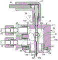
FIG. 2 is an enlarged vertical cross-section of an electrostatic liquid dispensing head of the illustrated system;
FIG. 3 is an enlarged cross-section of the circular detail labeled B in FIG. 2;
FIG. 4 is an enlarged partial perspective view of an electrostatic dispensing head applying a fine line lubricant to the end periphery of a can, such as during machining in a can necking operation; and
fig. 5 is an enlarged partial cross-section illustrating adjustable mounting of a charging electrode within a nozzle body of the illustrated electrostatic dispensing head.
While the invention is susceptible to various modifications and alternative constructions, certain illustrated embodiments thereof have been shown in the drawings and will be described below in detail. It should be understood, however, that there is no intention to limit the invention to the specific forms disclosed, but on the contrary, the intention is to cover all modifications, alternative constructions, and equivalents falling within the spirit and scope of the invention.
Detailed Description
Referring now more particularly to the drawings, there is shown an exemplary lubricant dispensing system 10 according to the present invention. The illustrated lubricant dispensing system 10 is shown for use in applying hot melt wax to the end periphery of a beverage can 11, such as during processing by a high speed can necking machine. In this case, the lubricant dispensing system 10 includes: a heating tank or container 12 with an internal pumping system for holding a quantity of lubricant (such as wax in a heated state); an electrostatic spray head 14 coupled to the tank 12 by supply and return conduits 15,16, respectively; and a controller 18 for controlling power to the electrostatic spray head 14. As will be understood by those skilled in the art, in can necking machines, beverage cans are simultaneously rotated as they are conveyed through a coating station where a small amount of lubricant is applied to the end periphery of the can. As will be appreciated by those skilled in the art, the present invention is not limited to this particular application, but may be used in any application involving the fine line coating of components or assemblies, whether made of conductive or non-conductive materials, such as, for example, electronic components, micro metal stampings, and the like. Also, the present invention is applicable to lubricant dispensing systems, whether or not the lubricant is heated.
The illustrated spray head 14 includes a generally cylindrical nozzle body 20 defining an internal liquid-receiving chamber 21, in this case the liquid-receiving chamber 21 serving as a liquid supply and recirculation chamber 21. In this case, the nozzle body 20 has a two-part construction, including an upper cylindrical body section 20aAnd a bottom spray tip holding section 20b. In this case, the bottom section 20bHaving a right cylindrical wall 22 with an externally threaded section 24 for engaging and retaining in the upper body section 20aAnd defines a lower portion of the liquid supply and recirculation chamber 21. In this case, a pair of hose connection couplings 25,26 are threadedly supported to the upper body section 20aIn order to enable easy connection and removal of the lubricant supply and return ducts 15,16, respectively. A sealing annular O-ring 28 is inserted between the radially extending wall 29 of the bottom body section 20b and the upper body section 20aBetween the lower sides of the plates. Body section 20a20b are preferably made of a non-metallic plastic material such as sold under the brand name Ultem which has a high dielectric strength and melting point and is amenable to economical machine manufacture.
In this case, the bottom nozzle body section 20bThe capillary tube 30 is supported within an upright support member, which in this case is a cylindrical column 31 disposed centrally in the liquid supply or recirculation chamber 21. The capillary tube 30 is preferably made of stainless steel and has an inner diameter of between about 0.020 and 0.032 inches. In this case, the nozzle body bottom section 20bFormed with a depending conical extension 32, bristlesThe tubule 30 protrudes through the depending conical extension 32 a small distance "l" to define a liquid discharge orifice 30 of the spray head 14a. The uppermost portion of the upstanding post 31 is formed with an enlarged diameter inlet passage 35 for conveying liquid between the liquid supply and recirculation chamber 21 and the capillary tube 30.
To charge the liquid as it is directed around the recirculation chamber 21 and through the inlet passage 35 and capillary tube 30, the spray head 14 has an elongated high voltage electrode 40 supported from the upper nozzle body section 20aAnd extends in a depending manner into the liquid supply and recirculation chamber 21. The electrode 40 may be made of any suitable electrically conductive material, and in this case is supported to the upper nozzle body section 20aWithin the upstanding inner collar 41. To couple the electrode 40 to a high voltage power supply, a spark plug sheath 42 of conventional type is fitted over the upstanding end of the electrode 40 to connect the electrode 40 to a high voltage charging cable 44 connected to the controller 18. It should be appreciated that the sheath 42 may be configured for quick disconnection and connection of the electrode 40 to the cable 44.
It can be seen that the lubricant introduced into the liquid supply and recirculation chamber 21 through the supply line 15 is not only charged by the electrodes 40, but is also directed around the chamber 21 for recirculation to the heating reservoir 12 through the return line 16 for the purpose of maintaining the nozzle body 20 and capillary tube 30 within a narrow temperature range without freezing or overheating the lubricant, and at the same time maintaining an electrostatic charge of the liquid substantially isolated within the chamber.
To control the flow rate of liquid to and through the capillary 30 to enhance liquid charge and thin line liquid discharge, the lower end of the electrode 40 has a lower tapered tip 40aWhich cooperates with a similarly angled conical valve seat 48 in the upper end of the nozzle body post 31 and the inlet passage 35 to the capillary tube 30. Pointed electrode tip 40aThe similarly tapered sides of and the valve seat 48 of the post inlet passage 35 define a relatively small gap or passage 50 through which liquid can pass at a precisely controlled relatively small volume rate. Pointed electrode tip 40aThe transfer of electrons to the liquid is further enhanced because the maximum concentration of electrons is at the tip of the tip.
It can be seen that the electrostatic charge applied to the liquid as it passes through the capillary tube 30 inside the nozzle body 20 causes repulsion of similarly charged molecules as the liquid is discharged from the capillary tube 30. As the fluid stream exits the capillary tube 30, the repulsion causes the liquid to break up into a single stream of atomized droplets having a registered relationship with each other. With the droplets positively charged and the tank 11 passing over the ground, the droplets can be precisely directed towards the target (i.e. in a substantially direct path, the uppermost periphery of the tank 11). This enables the spray head 14 to maintain liquid discharge within a precisely controlled range, such as about 0.125 inches or less, for application of thin lines 51 of lubricant (fig. 4) as is particularly needed for coating cans in can necking machines. This atomization and direction of lubricant is further advantageous because it minimizes pressure drop in the direction of the liquid and can operate accurately at low flow rates that prevent over-application, lubricant waste, and product defects from occurring.
According to yet another feature of the illustrated embodiment, the electrode 40 is used to charge the lubricant and control and regulate the flow rate of the liquid as it is directed through the spray head 14. As illustrated in fig. 2 and 5, the charging electrode 40 is threadedly supported within a threaded section 54 of the raised collar 41 of the nozzle body 20, and the upper protruding end of the electrode is formed with a pair of flats 55 which can be easily engaged by a wrench to rotate the electrode 40 when the sheath 42 is removed so that the lower end can be accurately positioned relative to the horizontal valve seat 48 for a desired flow rate. Thus, the liquid flow rate can be precisely adjusted for the particular application of the fine line spray. In this case, an O-ring 58 is inserted between the electrode 40 and the nozzle body 20 at a location inside the threaded section 54 for preventing possible leakage.
As can be seen from the above, an electrostatic spray system is provided for the uniform and efficient application of hot melt waxes, oils and other lubricants. While the system is particularly suited for applying a thin line of lubricant to a metallic component, such as to a precisely controlled target area around the periphery of a can in a high speed can necking machine, it can be used in numerous other spray applications, whether involving metallic or non-metallic components. The dispensing system also lends itself to easy adjustability for particular spray applications while also being relatively simple in construction.
Claims (6)
1. A lubricant dispensing system, comprising:
a lubricant supply (12);
an electrostatic spray head (14) for receiving lubricant from the lubricant supply (12);
the spray head (14) comprises: a nozzle body (20) defining a lubricant receiving chamber (21);
an electrode assembly comprising an electrode (40) mounted in the nozzle body (20) and connected to a high voltage power supply so as to electrostatically charge lubricant directed into the lubricant receiving chamber (21);
a capillary tube (30) supported within a support member (31) of the nozzle body (20);
the capillary tube (30) having an inlet end communicating with the lubricant receiving chamber (21) and an outlet end defining a discharge orifice (30 a) of the electrostatic spray head (14);
the capillary (30) having an inner diameter dimension of between 0.020 and 0.032 inches for directing electrostatically charged lubricant from the spray head (14) in aligned relation in a single stream of electrostatically charged droplets for application onto an article to be lubricated (11) in a tightly controlled line (51) having a width of no greater than 0.125 inches;
the support member (31) has an inlet channel section (48) communicating with the inlet end of the capillary tube (30), and
the electrode (40) is adjustably positionable relative to the nozzle body (20) and has a tapered tip (40 a), the tip (40 a) being selectively positionable into the entry channel section (48) of the support member (31) for precisely adjustably controlling the flow rate of lubricant into and through the capillary tube (30) and onto an item to be lubricated.
2. The lubricant dispensing system of claim 1, wherein the lubricant supply comprises: a heating container (12) for heating the lubricant; a lubricant supply line (15) communicating between the heating reservoir (12) and the nozzle body (20) and for guiding heated lubricant to the lubricant receiving chamber (21); and a lubricant return line (16) for recirculating lubricant from the lubricant receiving chamber (21) to the heating reservoir (12).
3. The lubricant dispensing system (10) of claim 1, wherein said electrode (40) is threadably supported within said nozzle body (20) and is adjustably positionable in response to rotation of said electrode (40).
4. The lubricant dispensing system (10) of claim 1, wherein the entry channel section of the support member (31) is conically complementary to the conical downstream end (40 a) of the electrode (40).
5. The lubricant dispensing system (10) of claim 1, wherein said tapered end (40 a) of said electrode (40) has a pointed end to enhance electron transfer to said lubricant.
6. The lubricant dispensing system of claim 1, wherein the entry channel section of the support member is conically shaped such that the conical tip of the electrode and the conical entry channel section define an adjustable relatively small gap therebetween for controlling a flow rate of liquid through the capillary tube.
Applications Claiming Priority (3)
| Application Number | Priority Date | Filing Date | Title |
|---|---|---|---|
| US201462015113P | 2014-06-20 | 2014-06-20 | |
| US62/015113 | 2014-06-20 | ||
| PCT/US2015/036750 WO2015196110A1 (en) | 2014-06-20 | 2015-06-19 | Electrostatic spraying system |
Publications (2)
| Publication Number | Publication Date |
|---|---|
| CN106457277A CN106457277A (en) | 2017-02-22 |
| CN106457277B true CN106457277B (en) | 2020-09-29 |
Family
ID=54936153
Family Applications (1)
| Application Number | Title | Priority Date | Filing Date |
|---|---|---|---|
| CN201580033209.0A Expired - Fee Related CN106457277B (en) | 2014-06-20 | 2015-06-19 | Electrostatic spraying system |
Country Status (15)
| Country | Link |
|---|---|
| US (1) | US10507477B2 (en) |
| EP (1) | EP3157682B1 (en) |
| JP (1) | JP6659595B2 (en) |
| KR (1) | KR102280550B1 (en) |
| CN (1) | CN106457277B (en) |
| BR (1) | BR112016029999B1 (en) |
| CA (1) | CA2952625C (en) |
| DK (1) | DK3157682T3 (en) |
| ES (1) | ES2860690T3 (en) |
| HU (1) | HUE053527T2 (en) |
| LT (1) | LT3157682T (en) |
| MX (1) | MX2016016847A (en) |
| PL (1) | PL3157682T3 (en) |
| PT (1) | PT3157682T (en) |
| WO (1) | WO2015196110A1 (en) |
Families Citing this family (1)
| Publication number | Priority date | Publication date | Assignee | Title |
|---|---|---|---|---|
| CN113560058B (en) * | 2021-07-22 | 2022-09-16 | 江苏大学 | Array integrated electrostatic atomization device capable of stabilizing multiple jet flow modes and experimental system |
Family Cites Families (15)
| Publication number | Priority date | Publication date | Assignee | Title |
|---|---|---|---|---|
| US3852095A (en) * | 1970-09-28 | 1974-12-03 | Nordson Corp | Method and apparatus for applying wax to can lid rims |
| DE3373279D1 (en) * | 1982-08-25 | 1987-10-08 | Ici Plc | Electrostatic entrainment pump for a spraying system |
| GB8604328D0 (en) * | 1986-02-21 | 1986-03-26 | Ici Plc | Producing spray of droplets of liquid |
| US5044564A (en) * | 1989-11-21 | 1991-09-03 | Sickles James E | Electrostatic spray gun |
| US5176321A (en) * | 1991-11-12 | 1993-01-05 | Illinois Tool Works Inc. | Device for applying electrostatically charged lubricant |
| GB9511514D0 (en) * | 1995-06-07 | 1995-08-02 | Ici Plc | Electrostatic spraying |
| JPH11104763A (en) * | 1997-09-29 | 1999-04-20 | Daiwa Can Co Ltd | Lubricant adhering device |
| CA2409093C (en) * | 2000-05-16 | 2009-07-21 | Regents Of The University Of Minnesota | High mass throughput particle generation using multiple nozzle spraying |
| DE60320535T2 (en) * | 2002-02-25 | 2009-06-10 | The Procter & Gamble Company, Cincinnati | ELECTROSTATIC SPRAYER |
| US7762801B2 (en) * | 2004-04-08 | 2010-07-27 | Research Triangle Institute | Electrospray/electrospinning apparatus and method |
| CN101351273B (en) * | 2005-11-03 | 2011-07-27 | 喷雾系统公司 | Electrostatic spray assembly |
| EP1979666B1 (en) * | 2006-02-02 | 2018-07-25 | Spraying Systems Co. | Electrostatic lubricant dispensing system |
| GB0709517D0 (en) * | 2007-05-17 | 2007-06-27 | Queen Mary & Westfield College | An electrostatic spraying device and a method of electrostatic spraying |
| DE102011007125A1 (en) | 2011-03-28 | 2014-02-13 | Aktiebolaget Skf | Metering device, lubrication system and method for dispensing a predetermined amount of lubricant |
| US20130140385A1 (en) * | 2011-08-17 | 2013-06-06 | Busek Co., Inc. | Charge injected fluid assist liquid atomizer |
-
2015
- 2015-06-19 BR BR112016029999-0A patent/BR112016029999B1/en active IP Right Grant
- 2015-06-19 MX MX2016016847A patent/MX2016016847A/en unknown
- 2015-06-19 PL PL15810369T patent/PL3157682T3/en unknown
- 2015-06-19 EP EP15810369.7A patent/EP3157682B1/en active Active
- 2015-06-19 ES ES15810369T patent/ES2860690T3/en active Active
- 2015-06-19 LT LTEP15810369.7T patent/LT3157682T/en unknown
- 2015-06-19 DK DK15810369.7T patent/DK3157682T3/en active
- 2015-06-19 CA CA2952625A patent/CA2952625C/en active Active
- 2015-06-19 JP JP2016573586A patent/JP6659595B2/en not_active Expired - Fee Related
- 2015-06-19 PT PT158103697T patent/PT3157682T/en unknown
- 2015-06-19 KR KR1020177000964A patent/KR102280550B1/en not_active Application Discontinuation
- 2015-06-19 CN CN201580033209.0A patent/CN106457277B/en not_active Expired - Fee Related
- 2015-06-19 HU HUE15810369A patent/HUE053527T2/en unknown
- 2015-06-19 US US15/320,427 patent/US10507477B2/en active Active
- 2015-06-19 WO PCT/US2015/036750 patent/WO2015196110A1/en active Application Filing
Also Published As
| Publication number | Publication date |
|---|---|
| PT3157682T (en) | 2021-03-23 |
| EP3157682B1 (en) | 2021-02-24 |
| KR20170020856A (en) | 2017-02-24 |
| DK3157682T3 (en) | 2021-03-22 |
| EP3157682A4 (en) | 2018-08-08 |
| PL3157682T3 (en) | 2021-06-28 |
| LT3157682T (en) | 2021-04-12 |
| BR112016029999A2 (en) | 2017-10-24 |
| EP3157682A1 (en) | 2017-04-26 |
| CA2952625A1 (en) | 2015-12-23 |
| BR112016029999B1 (en) | 2021-03-23 |
| JP6659595B2 (en) | 2020-03-04 |
| WO2015196110A1 (en) | 2015-12-23 |
| ES2860690T3 (en) | 2021-10-05 |
| KR102280550B1 (en) | 2021-07-26 |
| US10507477B2 (en) | 2019-12-17 |
| CN106457277A (en) | 2017-02-22 |
| HUE053527T2 (en) | 2021-07-28 |
| MX2016016847A (en) | 2017-10-12 |
| US20170189921A1 (en) | 2017-07-06 |
| CA2952625C (en) | 2022-10-04 |
| JP2017519626A (en) | 2017-07-20 |
Similar Documents
| Publication | Publication Date | Title |
|---|---|---|
| EP1979666B1 (en) | Electrostatic lubricant dispensing system | |
| EP3046676B1 (en) | Electrostatic spray nozzle assembly | |
| US2893894A (en) | Method and apparatus for electrostatically coating | |
| CN101163555A (en) | Device for applying fluids to a contour of a substrate | |
| JPS6250192B2 (en) | ||
| CN107684985B (en) | Swivel joint, spraying method and spraying machine comprising swivel joint | |
| CN106457277B (en) | Electrostatic spraying system | |
| CA3035437C (en) | Device and method for producing pulverulent plastics with a spherical structure | |
| US4869201A (en) | Apparatus for coating can barrels | |
| EP0032212B1 (en) | Apparatus and method for the lubrication of cans | |
| CN101120121A (en) | Method of electrodepositing hub | |
| CN105331771A (en) | Passivator adding device for producing passivated lime and using method of passivator adding device | |
| JP3214936U (en) | Circulating spray gun for zinc rich paint | |
| JP2010279853A (en) | Apparatus and method of manufacturing solid lubricant coated metal sheet | |
| US20240042466A1 (en) | Narrow point electrostatic spray nozzle assembly and lubricant dispensing system | |
| US20020092922A1 (en) | Spraying method and a spray system for coating liquids | |
| CN219881975U (en) | Trace lubrication atomization cooling device | |
| US20210040408A1 (en) | Lubricating method for drawing and lubricant for said method | |
| WO1995008396A1 (en) | Method, applicator and apparatus for electrostatic coating | |
| US9067817B2 (en) | System and method to coat glass gobs with a lubricating dispersion during the drop to blank molds | |
| CN111512704A (en) | Method for manufacturing web, method for controlling electrification, and electrification control device | |
| JP2012192336A (en) | Oil application method, and oil applicator using the same | |
| TWM452808U (en) | Air pre-heating type coating device | |
| JP2015061723A (en) | Coating method and coating device of liquid coating |
Legal Events
| Date | Code | Title | Description |
|---|---|---|---|
| C06 | Publication | ||
| PB01 | Publication | ||
| SE01 | Entry into force of request for substantive examination | ||
| SE01 | Entry into force of request for substantive examination | ||
| GR01 | Patent grant | ||
| GR01 | Patent grant | ||
| CF01 | Termination of patent right due to non-payment of annual fee | ||
| CF01 | Termination of patent right due to non-payment of annual fee |
Granted publication date: 20200929 Termination date: 20210619 |