CN105918269B - Dual-bearing reel - Google Patents
Dual-bearing reel Download PDFInfo
- Publication number
- CN105918269B CN105918269B CN201610097865.3A CN201610097865A CN105918269B CN 105918269 B CN105918269 B CN 105918269B CN 201610097865 A CN201610097865 A CN 201610097865A CN 105918269 B CN105918269 B CN 105918269B
- Authority
- CN
- China
- Prior art keywords
- reel
- spool
- bearing
- dual
- reel body
- Prior art date
- Legal status (The legal status is an assumption and is not a legal conclusion. Google has not performed a legal analysis and makes no representation as to the accuracy of the status listed.)
- Active
Links
Images
Classifications
-
- A—HUMAN NECESSITIES
- A01—AGRICULTURE; FORESTRY; ANIMAL HUSBANDRY; HUNTING; TRAPPING; FISHING
- A01K—ANIMAL HUSBANDRY; CARE OF BIRDS, FISHES, INSECTS; FISHING; REARING OR BREEDING ANIMALS, NOT OTHERWISE PROVIDED FOR; NEW BREEDS OF ANIMALS
- A01K89/00—Reels
-
- A—HUMAN NECESSITIES
- A01—AGRICULTURE; FORESTRY; ANIMAL HUSBANDRY; HUNTING; TRAPPING; FISHING
- A01K—ANIMAL HUSBANDRY; CARE OF BIRDS, FISHES, INSECTS; FISHING; REARING OR BREEDING ANIMALS, NOT OTHERWISE PROVIDED FOR; NEW BREEDS OF ANIMALS
- A01K89/00—Reels
- A01K89/015—Reels with a rotary drum, i.e. with a rotating spool
- A01K89/0192—Frame details
- A01K89/0193—Frame details with bearing features
-
- A—HUMAN NECESSITIES
- A01—AGRICULTURE; FORESTRY; ANIMAL HUSBANDRY; HUNTING; TRAPPING; FISHING
- A01K—ANIMAL HUSBANDRY; CARE OF BIRDS, FISHES, INSECTS; FISHING; REARING OR BREEDING ANIMALS, NOT OTHERWISE PROVIDED FOR; NEW BREEDS OF ANIMALS
- A01K89/00—Reels
- A01K89/015—Reels with a rotary drum, i.e. with a rotating spool
- A01K89/0183—Drive mechanism details
-
- A—HUMAN NECESSITIES
- A01—AGRICULTURE; FORESTRY; ANIMAL HUSBANDRY; HUNTING; TRAPPING; FISHING
- A01K—ANIMAL HUSBANDRY; CARE OF BIRDS, FISHES, INSECTS; FISHING; REARING OR BREEDING ANIMALS, NOT OTHERWISE PROVIDED FOR; NEW BREEDS OF ANIMALS
- A01K89/00—Reels
- A01K89/015—Reels with a rotary drum, i.e. with a rotating spool
- A01K89/0192—Frame details
-
- A—HUMAN NECESSITIES
- A01—AGRICULTURE; FORESTRY; ANIMAL HUSBANDRY; HUNTING; TRAPPING; FISHING
- A01K—ANIMAL HUSBANDRY; CARE OF BIRDS, FISHES, INSECTS; FISHING; REARING OR BREEDING ANIMALS, NOT OTHERWISE PROVIDED FOR; NEW BREEDS OF ANIMALS
- A01K89/00—Reels
- A01K89/02—Brake devices for reels
- A01K89/033—Brake devices for reels with a rotary drum, i.e. for reels with a rotating spool
Abstract
The invention provides a dual-bearing reel capable of improving the accuracy of the concentricity of an annular wall with respect to a spool shaft. A dual-bearing reel includes a reel body, a spool (3), and an interposed member (4). The reel body has a first reel body (21) and a second reel body. The first reel body (21) includes a first through-hole (24) extending in the direction of the rotation axis. The spool is rotatably disposed between the first reel body and the second reel body. The spool has a spool body portion and a first flange portion (32). The first flange portion is formed at an end portion of the spool portion on the first reel unit side. The intermediate member is disposed between the first reel body and the spool. The intermediate member is attached to the first reel body. The intermediate member has an annular wall (41) and a second through hole (42). The annular wall includes an inner peripheral surface facing the outer peripheral surface of the first flange portion.
Description
Technical Field
The invention relates to a dual-bearing reel.
Background
A dual-bearing reel includes: a frame having a first side plate and a second side plate; and the winding drum is configured between the first side plate and the second side plate. The first side plate has an annular wall formed to face the outer peripheral surface of the flange portion of the spool in order to prevent a fishing line from entering a gap between the flange portion and the first side plate (for example, patent document 1). The gap between the inner peripheral surface of the annular wall and the outer peripheral surface of the flange portion is adjusted to prevent the fishing line from entering between the flange portion and the first side plate.
Documents of the prior art
Patent document 1: japanese patent laid-open No. 2014-100078.
When the gap between the inner peripheral surface of the annular wall and the outer peripheral surface of the flange portion is not small, a fishing line may intrude therebetween. Further, even if the two are partially in contact with each other, smooth rotation of the drum is inhibited. Therefore, accuracy of concentricity of the annular wall with respect to the spool shaft is required. However, since the annular wall is formed by cutting on the first side plate facing the second side plate, and the first side plate is configured to face the second side plate, there is a limit to the accuracy of improving the concentricity of the annular wall.
Disclosure of Invention
The invention provides a dual-bearing reel capable of improving the accuracy of the concentricity of an annular wall with respect to a spool shaft.
A dual-bearing reel according to one aspect of the present invention includes a reel body, a spool, and an interposed member. The reel body has a first reel body portion and a second reel body portion. The first reel body includes a first through hole extending in the direction of the rotation axis. The spool is rotatably disposed between the first reel body and the second reel body. The spool has a spool body portion and a flange portion. The flange portion is formed at an end of the spool portion on the first reel unit side. The intermediate member is disposed between the first reel body and the spool. The intermediate member is attached to the first reel body. The intermediate member has an annular wall and a second through hole. The annular wall includes an inner peripheral surface facing the outer peripheral surface of the flange portion. The second through hole extends in the direction of the rotation axis.
According to this configuration, the annular wall is not formed on the reel unit, but formed on an interposed member that is a separate member from the reel unit. Therefore, the annular wall can be easily formed, and the accuracy of the concentricity of the annular wall with respect to the spool shaft can be improved.
Preferably, the dual-bearing reel further includes a first bearing member. The first bearing member is disposed in the second through hole and rotatably supports the spool.
Preferably, the dual-bearing reel further includes a pinion gear and a second bearing member. The pinion gear extends in the direction of the rotation axis in the first reel body. The second bearing member is disposed in the first through hole and rotatably supports the pinion gear.
Preferably, the second through hole has a first inner diameter portion, and the inner diameter of the first inner diameter portion is smaller than the inner diameter of the first through hole. The first end surface of the second bearing member is opposed to the interposed member. According to this configuration, the step portion is formed by the difference in inner diameter between the first inner diameter portion and the first through hole. The step portion restricts the axial movement of the second bearing member.
Preferably, the second through hole has a second inner diameter portion having an inner diameter larger than that of the first inner diameter portion. The first bearing component is arranged on the second inner diameter part. According to this configuration, the step portion formed by the first inner diameter portion and the second inner diameter portion can restrict the movement of the first bearing member in the axial direction.
Preferably, the interposed member is made of synthetic resin. According to this structure, there is no need to perform complicated post-processing or surface treatment for rust prevention and corrosion resistance.
Preferably, the dual-bearing reel further includes a handle, a clutch mechanism, and a clutch operating member. The handle is rotatably fitted to the reel body. The handle is a member for rotating the drum. The clutch mechanism is switched between a transmission state in which rotation is transmitted between the handle and the spool and a disconnection state in which the transmission of rotation is disconnected. The clutch operating member is operated by a user for switching the state of the clutch mechanism. The clutch operating member extends along an outer peripheral surface of the annular wall of the interposed member.
Preferably, the dual-bearing reel further includes a spool shaft that rotates integrally with the spool. The pinion gear is engaged with the spool shaft by moving in the axial direction in a direction approaching the second reel body. The pinion gear is disengaged from the spool shaft by moving in the axial direction in a direction away from the second reel body.
Preferably, the spool shaft has an engaging pin protruding in the radial direction. The pinion gear has an engagement recess that can engage with the engagement pin.
Effects of the invention
According to the present invention, the accuracy of the concentricity of the annular wall with respect to the spool shaft can be improved.
Drawings
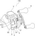
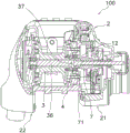
Fig. 1 is a perspective view of a dual-bearing reel.
Fig. 2 is a cross-sectional view of the dual-bearing reel.
Fig. 3 is an enlarged cross-sectional view of the dual-bearing reel.
Fig. 4 is an exploded view of the dual-bearing reel.
Fig. 5 is a cross-sectional view of the dual-bearing reel.
Fig. 6 is a cross-sectional view of the dual-bearing reel.
Description of the reference numerals
2 reel body
21 first reel body
22 second reel body
24 first through hole
3 winding drum
31 bobbin body
32 first flange part
36 reel shaft
37 engaging pin
4 clamping component
41 second annular wall
42 second through hole
42a first inner diameter part
42b second inner diameter part
5 Clutch operating Member
6 handle
7 pinion
71 engaging recess
72 steps
9 Clutch mechanism
11 first bearing component
12 second bearing component.
Detailed Description
Hereinafter, embodiments of a dual-bearing reel according to the present invention will be described with reference to the drawings. Fig. 1 is a perspective view of a dual-bearing reel, and fig. 2 is a cross-sectional view of the dual-bearing reel. In the following description, the rotation axis direction means a direction in which the rotation axis of the spool extends, that is, a direction in which the spool axis extends. The radial direction means a radial direction of a circle centered on the rotation axis of the drum, and the circumferential direction means a circumferential direction of a circle centered on the rotation axis of the drum. The radial view is a state viewed along the radial direction.
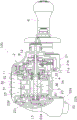
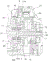
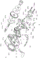
As shown in fig. 1, the dual-bearing reel 100 is configured to reel out fishing line in the forward direction. The dual-bearing reel 100 includes a reel body 2, a spool 3, an interposed member 4, a clutch operating member 5, and a handle 6. Also, as shown in fig. 2, the dual-bearing reel 100 further includes the pinion gear 7, the spool shaft 36, the clutch mechanism 9, and the first to third bearing members 11 to 13. The dual-bearing reel 100 according to the present embodiment is configured as an electric reel.
The reel body 2 includes a first reel body 21 and a second reel body 22. The first reel unit and the second reel unit are disposed at a distance from each other in the direction of the rotation axis. Specifically, the first reel body 21 is disposed on the first end side of the spool 3, and the second reel body 22 is disposed on the second end side of the spool 3. The first reel body 21 and the second reel body 22 are coupled to each other via a coupling portion 23. The handle 6 is rotatably fitted to the reel body 2. In detail, the handle 6 is rotatably fitted to the first reel body 21. By rotating the handle 6, the drum 3 is also rotated.
The first reel body 21 has a first side plate 21a and a first cover 21 b. The first reel body 21 has a housing space therein. The housing space is defined by the first side plate 21a and the first cover 21 b.
As shown in FIG. 3, the first reel body 21 has: a protruding portion 21e that protrudes cylindrically toward the second reel unit side; and a first through-hole 24 formed in the center of the protruding portion 21 e. The first through hole 24 extends in the rotation axis direction and opens toward the second reel body 22. The first through hole 24 communicates the interior and exterior of the first reel body 21. The second bearing member 12 is disposed in the first through hole 24. The second bearing member 12 rotatably supports the pinion gear 7. Further, no groove or the like is formed on the inner peripheral surface of the first through hole 24.
As shown in fig. 4, the rotation transmission mechanism 101 is accommodated in the accommodation space. The rotation transmission mechanism 101 is a mechanism that transmits the rotation of the handle 6 to the reel 3 and the like. The rotation transmission mechanism 101 includes a drive shaft 101a that rotates integrally with the handle 6, a drive gear 101b that rotates integrally with the drive shaft 101a, and the like. The drive gear 101b meshes with the pinion gear 7.
As shown in FIG. 2, the second reel body 22 has a second side plate 22a and a second cover 22 b. The second side plate 22a is connected to the first side plate 21a via a joint 23. The first side plate 21a, the second side plate 22a, and the coupling portion 23 are integrally formed, thereby constituting a frame of the reel unit 2. For example, the first side plate 21a, the second side plate 22a, and the coupling portion 23 are integrally formed by die-casting using an aluminum alloy.
The second reel body 22 has a support portion 22 c. The support portion 22c is attached to at least one of the second side plate 22a and the second cover 22 b. The support portion 22c has a recess 22d for holding the third bearing member 13. The recess 22d extends in the direction of the rotation axis and opens toward the first reel body 21.
The support portion 22c has a first annular wall 22 e. The inner peripheral surface of the first annular wall 22e faces the outer peripheral surface of a second flange 33 of the drum 3, which will be described later. The first annular wall 22e is formed at the outer peripheral end of the support portion 22c and projects toward the first reel body 21 side.
The spool 3 is rotatably disposed between the first reel body 21 and the second reel body 22. The roll 3 is mounted on the roll shaft 36 and rotates integrally with the roll shaft 36. For example, the spool 3 and the spool shaft 36 are fixed together by spline fitting or the like so as not to be rotatable relative to each other.
The spool 3 includes a bobbin portion 31, a first flange portion 32, and a second flange portion 33. The first flange portion 32 corresponds to the flange portion of the present invention. The winding body 31 has a cylindrical shape and extends in the direction of the rotation axis. The fishing line is wound around the outer peripheral surface of the winding body 31.
The first flange portion 32 and the second flange portion 33 extend radially outward from both ends of the bobbin portion 31. Specifically, the first flange portion 32 is formed at the end of the spool portion 31 on the first reel body 21 side. The second flange portion 33 is formed at the end of the spool portion 31 on the second reel body 22 side. The outer peripheral surface of the second flange portion 33 faces the inner peripheral surface of the first annular wall 22e as described above.
The reel 3 also has a first boss portion 34 and a second boss portion 35. The first and second boss portions 34, 35 extend in the rotational axis direction. In detail, the first boss portion 34 extends from the spool body portion 31 toward the first reel body portion 21. The second boss portion 35 extends from the spool portion 31 toward the second reel body 22.
The spool shaft 36 is rotatably supported by the interposed member 4 attached to the first reel body 21 and the second reel body 22. Specifically, the spool shaft 36 is supported by the second reel unit 22 via the third bearing member 13. The spool shaft 36 rotates integrally with the spool 3. The spool shaft 36 has an engaging pin 37 projecting in the radial direction.
The pinion gear 7 is disposed in the first reel body 21. The pinion gear 7 extends in the direction of the rotation axis. The pinion gear 7 is supported by the first reel unit 21 via the second bearing member 12. The pinion gear 7 is movable in the direction of the rotation axis.
As shown in fig. 3, the pinion gear 7 has an engagement recess 71 that can engage with the engagement pin 37. The engagement recess 71 is formed in the end of the pinion gear 7 on the second reel body 22 side. The pinion gear 7 has a stepped portion 72 facing the second end face of the second bearing member 12. The step 72 restricts the movement of the second bearing member 12 in a direction away from the second reel unit 22. In addition, the second end surface of the second bearing member 12 faces the opposite side of the second reel unit 22 side. Namely, the second end face of the second bearing member 12 faces the handle 6 side.
The clutch mechanism 9 is switched between a transmission state and a disconnection state. When the clutch mechanism 9 is in the transmission state, rotation is transmitted between the handle 6 and the drum 3. When the clutch mechanism 9 is in the disengaged state, the transmission of the rotation is interrupted. Specifically, the clutch mechanism 9 is constituted by the engagement pin 37 and the engagement recess 71. As shown in fig. 5, the engagement of the engagement pin 37 with the engagement recess 71 is released by the pinion gear 7 moving in a direction away from the second reel body 22. As a result, the pinion gear 7 can rotate relative to the spool shaft 36. That is, the clutch mechanism 9 is in the disengaged state. On the other hand, the pinion gear 7 moves in a direction approaching the second reel body 22, so that the engagement pin 37 engages with the engagement recess 71 as shown in fig. 3. As a result, the pinion gear 7 can rotate integrally with the spool shaft 36. That is, the clutch mechanism 9 is in the transmission state.
Here, in the present embodiment, since the movement of the second bearing member 12 in the direction away from the second reel body 22 is restricted by the stepped portion 72 of the pinion gear 7, the following effects are obtained. That is, even when the second bearing member 12 is fixed to the pinion gear 7, the pinion gear 7 can move in a direction away from the second reel unit 22 together with the second bearing member 12, as shown in fig. 6.
As shown in fig. 3, the interposed member 4 is disposed between the first reel body 21 and the spool 3. The interposed member 4 is, for example, synthetic resin. The interposed member 4 is a separate member from the reel unit 2, and is attached to the first reel unit 21. The interposed member 4 has a second annular wall 41 and a second through hole 42. Specifically, the interposed member 4 is disc-shaped, and the second annular wall 41 is formed at an outer peripheral end portion of the interposed member 4. The second through hole 42 is formed in the central portion of the interposed member 4. The second through-hole 42 is formed so as to be continuous with the recess 4a provided on the first reel body 21 side. The second annular wall 41 corresponds to the annular wall of the present invention.
The second annular wall 41 protrudes toward the second reel body 22 side. The second annular wall 41 is configured to surround the first flange portion 32. That is, the inner peripheral surface of the second annular wall 41 faces the outer peripheral surface of the first flange 32. The inner peripheral surface of the second annular wall 41 and the outer peripheral surface of the first flange portion 32 are disposed at a distance from each other, but the inner peripheral surface of the second annular wall 41 and the outer peripheral surface of the first flange portion 32 may be in contact with each other. In addition, the second annular wall 41 may completely overlap the first flange 32 or may partially overlap the first flange when viewed in the radial direction.
The second through hole 42 extends in the rotation axis direction. The first bearing member 11 is disposed in the second through hole 42. The first bearing member 11 rotatably supports the reel 3. Specifically, the first bearing member 11 rotatably supports the first boss portion 34.
The second through hole 42 has a first inner diameter portion 42a and a second inner diameter portion 42 b. The inner diameter of the first inner diameter portion 42a is smaller than the inner diameter of the first through hole 24. That is, the inner diameter of the first inner diameter portion 42a is smaller than the outer diameter of the second bearing member 12. Therefore, the first end surface of the second bearing member 12 faces the interposed member 4. That is, the movement of the second bearing member 12 toward the second reel unit 22 is restricted by the interposed member 4. The first end surface of the second bearing member 12 faces the second reel body 22 side. In addition, in the conventional dual-bearing reel, the annular groove is formed in the first through-hole 24, and the snap ring for restricting the movement of the second bearing member 12 toward the second reel body portion 22 side is provided in the annular groove, but in the present embodiment, it is not necessary to form the annular groove in the first through-hole 24 or provide the snap ring. Therefore, the processing for forming the first through hole 24 is facilitated.
The inner diameter of the second inner diameter portion 42b is larger than the inner diameter of the first inner diameter portion 42 a. The first bearing member 11 is disposed on the second inner diameter portion 42 b. The first bearing member 11 is restricted from moving toward the first reel unit 21 by a step defined by the first inner diameter portion 42a and the second inner diameter portion 42 b.
The first reel body protruding portion 21e fits into the recessed portion 4a of the interposed member 4, thereby ensuring concentricity between the first through hole 24 and the second through hole 42, that is, concentricity between the first bearing member 11 and the second bearing member 12 and the second annular wall 41.
As shown in fig. 1, the clutch operating member 5 is a member operated by a user to switch the state of the clutch mechanism 9. The state of the clutch mechanism 9 is switched between the transmission state and the disconnection state by the user operating the clutch operating member 5. The clutch operating member 5 is swingable about a rotation axis. The clutch operating member 5 has a clutch release operating portion 51 and a clutch engagement operating portion 52.
The clutch release operation unit 51 is disposed behind the drum 3. The clutch release operating portion 51 extends between the first reel body 21 and the second reel body 22. The user operates the clutch release operation unit 51 to press down, thereby bringing the clutch mechanism 9 into the disengaged state.
The clutch engagement operation unit 52 is a part that is operated by the user when the clutch mechanism 9 is set to the transmission state. Specifically, the user presses the clutch engagement operation portion 52 forward to set the clutch mechanism 9 in the transmission state. That is, the clutch engagement operating portion 52 moves forward, so that the clutch mechanism 9 is in the transmission state.
The clutch engagement operation portion 52 extends along the outer peripheral surface of the second annular wall 41 of the interposed member 4. The clutch engagement operating portion 52 protrudes toward the second reel body 22. In detail, the tip end portion 52a of the clutch engagement operating portion 52 protrudes toward the second reel body 22. That is, the distal end portion 52a protrudes in the axial direction. The user can set the clutch mechanism 9 in the transmission state by pressing the distal end portion 52a forward.
As shown in fig. 4, the clutch operating member 5 also has a bottom plate 53. The clutch release operation portion 51 is attached to the base plate 53. The bottom plate 53 extends between the first reel body 21 and the second reel body 22. The bottom plate 53 is slidably supported by the first guide groove 211 and the second guide groove 221. In addition, a first guide groove 211 is formed in the first side plate 21a of the first reel body 21 and extends in the circumferential direction. Also, the second guide groove 221 is formed in the second side plate 22a of the second reel body 22 and extends in the circumferential direction.
The bottom plate 53 has a fitting portion 53 a. The fitting portion 53a is a portion that is fitted to the reel unit 2. The fitting portion 53a is rotatably fitted to the reel unit 2. In detail, the fitting portion 53a is fitted to the mounting plate 21 c. The mounting plate 21c is fixed to the first side plate 21 a. The mounting plate 21c has a boss portion 21 d. The boss portion 21d is cylindrical and protrudes outward in the axial direction. The fitting portion 53a has an opening in the central portion. The boss portion 21d is inserted into the opening of the fitting portion 53a, whereby the fitting portion 53a is rotatably fitted to the boss portion 21 d.
The clutch operating member 5 operates a clutch mechanism 9 via a link mechanism 8. Specifically, when the user operates the clutch operating member 5 to move the pinion gear 7 in the axial direction, the clutch mechanism 9 is switched to the transmission state or the disconnection state. The link mechanism 8 includes a clutch cam 81, a pressing plate 82, and a clutch fork 83.
The clutch cam 81 rotates in conjunction with the bottom plate 53. The clutch cam 81 is disposed to be rotatable about the rotation axis O. The clutch cam 81 is rotatably attached to the attachment plate 21 c. Specifically, the clutch cam 81 has an opening in the center. By inserting the boss portion 21d of the attachment plate 21c into the opening, the clutch cam 81 is rotatably fitted to the boss portion 21 d.
The clutch cam 81 has a cam surface 81a and a projection 81 b. The cam surface 81a is configured to press the clutch fork 83 outward in the axial direction. Specifically, when the clutch cam 81 rotates counterclockwise as viewed from the outside in the axial direction, the cam surface 81a presses the clutch fork 83 outward in the axial direction, and the clutch plug 83 moves outward in the axial direction. The clutch cam 81 is made of, for example, synthetic resin.
The protrusion 81b is a portion protruding outward in the radial direction, and is a portion to which a return member 84 described later is attached. The clutch cam 81 further has an engaging convex portion 81 c. The engaging convex portion 81c protrudes inward in the axial direction. The engaging protrusion 81c engages with the engaging hole 53b of the bottom plate 53. By this engagement, the bottom plate 53 and the clutch cam 81 are integrally rotated about the rotation axis O.
The clutch fork 83 has an engagement portion 83 a. The cam surface 81a engages with the engagement portion 83a of the clutch fork 83, and presses the clutch fork 83 outward in the axial direction. The clutch fork 83 is supported by the pressing plate 82 so as to be movable in the axial direction. The pressing plate 82 is disposed in each opening of the bottom plate 53 and the clutch cam 81. The pressing plate 82 is fixed to the mounting plate 21 c.
The pressing plate 82 has a plurality of pins 82a extending in the axial direction. Each pin 82a extends outward in the axial direction. The clutch fork 83 has a through hole 83b at a position corresponding to each pin 82 a. The pins 82a are inserted into the through holes 83b, whereby the clutch fork 83 is supported to be movable in the axial direction.
The clutch fork 83 is configured to engage with the constricted portion 73 of the pinion gear 7. Therefore, the pinion gear 7 moves in the axial direction in conjunction with the clutch fork 83. Further, even if the pinion gear 7 rotates, the clutch fork 83 is not rotated. The clutch fork 83 is biased inward in the axial direction by a biasing member. Specifically, the plurality of coil springs 82b supported by the pins 82a of the pressing plate 82 urge the clutch fork 83 inward in the axial direction.
In a normal state, the clutch fork 83 is biased inward in the axial direction by the coil springs 82 b. Therefore, the engagement concave portion 71 of the pinion gear 7 engages with the engagement pin 37 of the spool shaft 36. That is, the clutch mechanism 9 connects the handle 6 and the drum 3. On the other hand, when the clutch operating member 5 is operated to move the clutch fork 83 outward in the axial direction, the engagement recess 71 of the pinion gear 7 is disengaged from the engagement pin 37. As a result, the clutch mechanism 9 disconnects the connection between the handle 6 and the drum 3.
The return member 84 is swingably fitted to the protruding portion 81b of the clutch cam 81. The return member 84 has a claw portion 84 b. The pawl 84b abuts against an outer peripheral portion of a ratchet 101c that rotates integrally with the drive shaft 101 a. The return member 84 is biased in both directions of the swing direction by a toggle spring 84 a. The pawl 84b of the return member 84 is pressed by the rotation of the ratchet 101c, and the clutch cam 81 is moved inward in the axial direction. That is, the clutch cam 81 returns from the clutch disengaged position to the clutch engaged position.
As described above, according to the dual-bearing reel 100 according to the present embodiment, the second annular wall 41 is formed not on the reel unit 2 but on the interposed member 4 that is a separate member from the reel unit 2. Therefore, the second annular wall 41 can be easily formed, and the accuracy of concentricity between the second annular wall 41 and the second through hole 42 can be improved. That is, the accuracy of the concentricity of the second annular wall 41 and the first bearing member 11 can be improved. Therefore, the accuracy of concentricity of the second annular wall 41 with respect to the spool shaft 36 can be improved.
[ modified examples ]
The embodiments of the present invention have been described above, but the present invention is not limited to these embodiments, and various modifications can be made without departing from the spirit of the present invention. For example, the dual-bearing reel 100 according to the above-described embodiment has been described as an electric reel, but the dual-bearing reel 100 may not be an electric reel.
Claims (8)
1. A dual-bearing reel, comprising:
a reel body having a first reel body portion including a first through hole extending in a rotation axis direction, and a second reel body portion;
a spool having a spool portion and a flange portion formed at an end of the spool portion on the first reel unit side, the spool being rotatably disposed between the first reel unit and the second reel unit; and
a clamping member having: an annular wall including an inner circumferential surface facing an outer circumferential surface of the flange portion; and a second through hole extending in the direction of the rotation axis, the interposed member being disposed between the first reel body and the spool and being attached to the first reel body,
the dual-bearing reel further includes:
a pinion gear extending in the direction of the rotation axis in the first reel body; and
a second bearing member disposed in the first through hole and rotatably supporting the pinion gear,
the pinion gear is supported by the first reel unit only via the second bearing member,
the mounting plate is attached to the first reel unit.
2. The dual-bearing reel of claim 1,
the dual-bearing reel further includes a first bearing member disposed in the second through-hole and rotatably supporting the spool.
3. The dual-bearing reel of claim 2,
the second through hole has a first inner diameter portion having an inner diameter smaller than that of the first through hole,
the first end surface of the second bearing member faces the interposed member.
4. The dual-bearing reel of claim 3,
the second through hole has a second inner diameter portion having an inner diameter larger than that of the first inner diameter portion,
the first bearing member is disposed on the second inner diameter portion.
5. The dual-bearing reel according to any one of claims 1 to 4,
the above-mentioned interposed member is made of synthetic resin.
6. The dual-bearing reel according to any one of claims 1 to 4,
the dual-bearing reel further includes:
a handle rotatably attached to the reel unit for rotating the spool;
a clutch mechanism that switches between a transmission state in which rotation is transmitted between the handle and the spool and a disconnection state in which the transmission of rotation is disconnected; and
a clutch operating member operated by a user to switch the state of the clutch mechanism,
the clutch operating member extends along an outer peripheral surface of the annular wall of the interposed member.
7. The dual-bearing reel according to any one of claims 1 to 4,
the dual-bearing reel further includes a spool shaft that rotates integrally with the spool,
the pinion gear is engaged with the spool shaft by moving in the axial direction in a direction approaching the second reel unit, and disengaged from the spool shaft by moving in a direction away from the second reel unit.
8. The dual-bearing reel of claim 7,
the spool shaft has an engaging pin projecting in the radial direction,
the pinion gear has an engagement recess that can engage with the engagement pin.
Applications Claiming Priority (2)
| Application Number | Priority Date | Filing Date | Title |
|---|---|---|---|
| JP2015-037117 | 2015-02-26 | ||
| JP2015037117A JP6530615B2 (en) | 2015-02-26 | 2015-02-26 | Double bearing reel |
Publications (2)
| Publication Number | Publication Date |
|---|---|
| CN105918269A CN105918269A (en) | 2016-09-07 |
| CN105918269B true CN105918269B (en) | 2021-06-25 |
Family
ID=56798048
Family Applications (1)
| Application Number | Title | Priority Date | Filing Date |
|---|---|---|---|
| CN201610097865.3A Active CN105918269B (en) | 2015-02-26 | 2016-02-23 | Dual-bearing reel |
Country Status (5)
| Country | Link |
|---|---|
| US (1) | US10028495B2 (en) |
| JP (1) | JP6530615B2 (en) |
| KR (1) | KR102562262B1 (en) |
| CN (1) | CN105918269B (en) |
| TW (1) | TWI688337B (en) |
Families Citing this family (3)
| Publication number | Priority date | Publication date | Assignee | Title |
|---|---|---|---|---|
| JP6979789B2 (en) * | 2017-05-18 | 2021-12-15 | 株式会社シマノ | Double bearing reel |
| JP6941560B2 (en) * | 2017-12-28 | 2021-09-29 | 株式会社シマノ | Bearing accommodation structure and double bearing reel |
| JP7345348B2 (en) * | 2019-10-16 | 2023-09-15 | 株式会社シマノ | double bearing reel |
Citations (6)
| Publication number | Priority date | Publication date | Assignee | Title |
|---|---|---|---|---|
| US5746381A (en) * | 1995-06-07 | 1998-05-05 | Daiwa Seiko, Inc. | Fishing reel with clutch mechanism utilizing an engaging protrusion and engaging recesses |
| EP0865730A2 (en) * | 1997-03-18 | 1998-09-23 | Daiwa Seiko Inc. | Fishline guide device for double bearing type reel |
| US5855330A (en) * | 1996-09-11 | 1999-01-05 | Daiwa Seiko, Inc. | Double bearing type reel for fishing |
| CN103210891A (en) * | 2012-01-18 | 2013-07-24 | 株式会社岛野 | Dual-bearing reel spool brake device and dual-bearing reel |
| CN103299967A (en) * | 2012-03-12 | 2013-09-18 | 株式会社岛野 | Dual-bearing reel |
| JP2014100078A (en) * | 2012-11-19 | 2014-06-05 | Shimano Inc | Double bearing reel |
Family Cites Families (24)
| Publication number | Priority date | Publication date | Assignee | Title |
|---|---|---|---|---|
| JPS55164970U (en) * | 1979-05-16 | 1980-11-27 | ||
| JPS5932284Y2 (en) * | 1979-07-06 | 1984-09-10 | オリムピツク釣具株式会社 | fishing reel |
| JPS635483Y2 (en) * | 1981-06-19 | 1988-02-15 | ||
| JPS5918868U (en) * | 1982-07-29 | 1984-02-04 | ダイワ精工株式会社 | Double bearing type reel for fishing |
| US4738409A (en) * | 1983-03-07 | 1988-04-19 | Shimano Industrial Company Limited | Fishing reel |
| JPS59139071U (en) * | 1983-03-07 | 1984-09-17 | 株式会社シマノ | double bearing reel |
| JPH0687722B2 (en) * | 1984-07-11 | 1994-11-09 | 島野工業株式会社 | Double bearing reel |
| US4830308A (en) * | 1984-07-25 | 1989-05-16 | Brunswick Corporation | Multiple cam mag brake adjustment for bait cast reel |
| JPH0810281Y2 (en) * | 1989-04-22 | 1996-03-29 | 株式会社シマノ | Double bearing reel |
| JP3033799B2 (en) | 1992-08-25 | 2000-04-17 | 古河機械金属株式会社 | Down the hole drill |
| KR100355073B1 (en) * | 1994-08-23 | 2003-01-06 | 다이와 세이꼬 가부시끼가이샤 | Ball bearing reel and fishing line parallel winding device |
| JPH08308447A (en) * | 1995-05-11 | 1996-11-26 | Daiwa Seiko Inc | Double bearing type reel for fishing |
| US5875986A (en) * | 1994-09-08 | 1999-03-02 | Daiwa Seiko, Inc. | Fishing reel of double bearing type having improved fishline releasing characteristic |
| JP3029295U (en) * | 1996-03-21 | 1996-09-27 | ダイワ精工株式会社 | Double bearing type reel for fishing |
| JP3033799U (en) * | 1996-06-20 | 1997-02-07 | ダイワ精工株式会社 | Double bearing reel for fishing |
| JP2000350537A (en) * | 1999-06-10 | 2000-12-19 | Ryobi Ltd | Clutch operation device for double bearing type reel |
| US6530535B2 (en) * | 2000-03-16 | 2003-03-11 | Daiwa Seiko, Inc. | Fishing reel |
| JP4381733B2 (en) * | 2003-06-26 | 2009-12-09 | 株式会社シマノ | Double bearing reel |
| JP2006238727A (en) * | 2005-03-01 | 2006-09-14 | Daiwa Seiko Inc | Fishing reel |
| JP2007159427A (en) * | 2005-12-09 | 2007-06-28 | Shimano Inc | Part for fishing |
| KR100891615B1 (en) * | 2007-06-01 | 2009-04-02 | 주식회사 바낙스 | Centrifugal brake apparatus of bait cast reel |
| JP5258688B2 (en) * | 2009-07-14 | 2013-08-07 | 株式会社シマノ | Double bearing reel sound generator |
| JP5686534B2 (en) * | 2010-06-21 | 2015-03-18 | 株式会社シマノ | Double-bearing reel rotation operation mechanism |
| JP6467188B2 (en) * | 2014-10-17 | 2019-02-06 | 株式会社シマノ | Fishing reel waterproof structure |
-
2015
- 2015-02-26 JP JP2015037117A patent/JP6530615B2/en active Active
-
2016
- 2016-02-01 TW TW105103155A patent/TWI688337B/en active
- 2016-02-03 US US15/014,788 patent/US10028495B2/en active Active
- 2016-02-11 KR KR1020160015421A patent/KR102562262B1/en active IP Right Grant
- 2016-02-23 CN CN201610097865.3A patent/CN105918269B/en active Active
Patent Citations (6)
| Publication number | Priority date | Publication date | Assignee | Title |
|---|---|---|---|---|
| US5746381A (en) * | 1995-06-07 | 1998-05-05 | Daiwa Seiko, Inc. | Fishing reel with clutch mechanism utilizing an engaging protrusion and engaging recesses |
| US5855330A (en) * | 1996-09-11 | 1999-01-05 | Daiwa Seiko, Inc. | Double bearing type reel for fishing |
| EP0865730A2 (en) * | 1997-03-18 | 1998-09-23 | Daiwa Seiko Inc. | Fishline guide device for double bearing type reel |
| CN103210891A (en) * | 2012-01-18 | 2013-07-24 | 株式会社岛野 | Dual-bearing reel spool brake device and dual-bearing reel |
| CN103299967A (en) * | 2012-03-12 | 2013-09-18 | 株式会社岛野 | Dual-bearing reel |
| JP2014100078A (en) * | 2012-11-19 | 2014-06-05 | Shimano Inc | Double bearing reel |
Also Published As
| Publication number | Publication date |
|---|---|
| US10028495B2 (en) | 2018-07-24 |
| KR102562262B1 (en) | 2023-08-02 |
| TWI688337B (en) | 2020-03-21 |
| KR20160104550A (en) | 2016-09-05 |
| CN105918269A (en) | 2016-09-07 |
| JP2016158509A (en) | 2016-09-05 |
| TW201633911A (en) | 2016-10-01 |
| JP6530615B2 (en) | 2019-06-12 |
| US20160249595A1 (en) | 2016-09-01 |
Similar Documents
| Publication | Publication Date | Title |
|---|---|---|
| KR102405034B1 (en) | Dual bearing reel | |
| CN105918269B (en) | Dual-bearing reel | |
| KR20130087411A (en) | Dual-bearing reel | |
| TWI714706B (en) | Clutch control mechanism for dual-bearing reel | |
| CN105707028B (en) | Dual-bearing reel | |
| JP7065598B2 (en) | Double bearing reel | |
| US10219501B2 (en) | Dual-bearing reel | |
| CN110731319B (en) | Fishing reel for fishing | |
| WO2014084090A1 (en) | Fishing reel | |
| JP2002084936A (en) | Double bearing reel | |
| CN110402902B (en) | Dual-bearing fishing reel | |
| CN105794744B (en) | Electric fishing line reel | |
| JP2022167022A (en) | fishing reel | |
| KR20130103611A (en) | Ignition switch for vehicle | |
| KR102615173B1 (en) | Roller clutch for fishing reel | |
| JP2019187343A5 (en) | ||
| JP2010124728A (en) | Fishing reel | |
| JP2022022394A (en) | Double bearing reel | |
| TW202116159A (en) | Dual-bearing reel | |
| JP2023131681A (en) | electric reel | |
| JP2001112386A (en) | Clutch apparatus for double bearing reel |
Legal Events
| Date | Code | Title | Description |
|---|---|---|---|
| C06 | Publication | ||
| PB01 | Publication | ||
| SE01 | Entry into force of request for substantive examination | ||
| SE01 | Entry into force of request for substantive examination | ||
| GR01 | Patent grant | ||
| GR01 | Patent grant |