JP2014100078A - Double bearing reel - Google Patents
Double bearing reel Download PDFInfo
- Publication number
- JP2014100078A JP2014100078A JP2012253053A JP2012253053A JP2014100078A JP 2014100078 A JP2014100078 A JP 2014100078A JP 2012253053 A JP2012253053 A JP 2012253053A JP 2012253053 A JP2012253053 A JP 2012253053A JP 2014100078 A JP2014100078 A JP 2014100078A
- Authority
- JP
- Japan
- Prior art keywords
- clutch
- spool
- side plate
- state
- fishing rod
- Prior art date
- Legal status (The legal status is an assumption and is not a legal conclusion. Google has not performed a legal analysis and makes no representation as to the accuracy of the status listed.)
- Pending
Links
Images


Classifications
-
- A—HUMAN NECESSITIES
- A01—AGRICULTURE; FORESTRY; ANIMAL HUSBANDRY; HUNTING; TRAPPING; FISHING
- A01K—ANIMAL HUSBANDRY; CARE OF BIRDS, FISHES, INSECTS; FISHING; REARING OR BREEDING ANIMALS, NOT OTHERWISE PROVIDED FOR; NEW BREEDS OF ANIMALS
- A01K89/00—Reels
- A01K89/015—Reels with a rotary drum, i.e. with a rotating spool
- A01K89/0192—Frame details
Abstract
Description
本発明は、両軸受リール、特に、釣り糸を前方に繰り出す両軸受リールに関する。 The present invention relates to a dual-bearing reel, and more particularly to a dual-bearing reel that feeds fishing line forward.
両軸受リールには、ハンドルとスプールとの回転を伝達するクラッチオン状態と回転の伝達を解除するクラッチオフ状態とを取り得るクラッチ機構が設けられる。クラッチ機構は、クラッチ操作部材によってクラッチオン状態とクラッチオフ状態とに切換操作可能である。従来の両軸受リールにおいて、クラッチ操作部材がリール本体の第1側板と第2側板の間に配置されるものが知られている(例えば、特許文献1参照)。従来の両軸受リールのクラッチ操作部材は、リール本体の後部に設けられる揺動軸回りに揺動自在に装着される。クラッチ操作部材は、板状の本体部と、本体部から突出して設けられる隆起部と、を有する。この両軸受リールでは、本体部を押し下げることにより、クラッチオン状態からクラッチオフ状態に切換操作を行える。また、隆起部を押し上げることにより、クラッチオフ状態からクラッチオン状態に切換操作できる。 The dual-bearing reel is provided with a clutch mechanism capable of taking a clutch-on state for transmitting the rotation of the handle and the spool and a clutch-off state for releasing the rotation. The clutch mechanism can be switched between a clutch-on state and a clutch-off state by a clutch operation member. A conventional dual-bearing reel is known in which a clutch operating member is disposed between a first side plate and a second side plate of a reel body (see, for example, Patent Document 1). A conventional clutch operating member of a dual-bearing reel is mounted so as to be swingable around a swing shaft provided at the rear portion of the reel body. The clutch operation member has a plate-like main body portion and a raised portion provided so as to protrude from the main body portion. In the dual-bearing reel, the switching operation from the clutch-on state to the clutch-off state can be performed by pushing down the main body. Further, by pushing up the raised portion, it is possible to switch from the clutch-off state to the clutch-on state.
従来の両軸受リールでは、クラッチ操作部材の隆起部を用いてクラッチオフ状態からクラッチオン状態にクラッチ機構の切換操作を行える。しかし、クラッチオフ状態のとき、本体部が後ろ下がりに大きく傾いているため、隆起部も後方に傾いてしまい、クラッチオン状態への切換操作を行いにくい。 In the conventional dual-bearing reel, the clutch mechanism can be switched from the clutch-off state to the clutch-on state using the raised portion of the clutch operation member. However, when the clutch is in the off state, the main body portion is greatly inclined backward and downward, so that the raised portion is also inclined backward, making it difficult to perform the switching operation to the clutch on state.
本発明の課題は、クラッチオン状態への切換操作を行える両軸受リールにおいて、クラッチオフ状態からクラッチオン状態への切換操作を容易に行えるようにすることにある。 An object of the present invention is to make it possible to easily perform a switching operation from a clutch-off state to a clutch-on state in a dual-bearing reel capable of switching operation to a clutch-on state.
発明1に係る両軸受リールは、釣り糸を前方に繰り出す両軸受リールである。両軸受リールは、リール本体と、ハンドルと、糸巻用のスプールと、クラッチ機構と、クラッチ操作部材と、を備える。リール本体は、第1側板及び第1側板と左右方向に間隔を隔てて配置される第2側板を有するフレームと、フレームに設けられる釣り竿装着部と、を有する。ハンドルは、リール本体の第1側板側に回転自在に装着される。スプールは、リール本体に回転可能に設けられる。クラッチ機構は、ハンドルの回転をスプールに伝達可能なクラッチオン状態と、回転をスプールに伝達不能なクラッチオフ状態と、に切換可能である。クラッチ操作部材は、第1側板と第2側板との間でリール本体の後部に釣り竿装着部に対して接近及び離反する方向に移動可能に設けられる。クラッチ操作部材は、クラッチ機構をクラッチオン状態とクラッチオフ状態とに切り換え操作するための部材である。クラッチ操作部材は、第1側板側に設けられる第1操作部と、第2側板側に設けられる第2操作部と、第1操作部よりも釣り竿装着部側に設けられる第3操作部と、を有する。第1操作部は、第2操作部よりも釣り竿装着部から離れて設けられる。第3操作部は、クラッチオフ状態からクラッチオン状態にクラッチ機構を戻すときに用いられる。 The dual-bearing reel according to the first aspect is a dual-bearing reel that feeds a fishing line forward. The dual-bearing reel includes a reel body, a handle, a spool for spooling, a clutch mechanism, and a clutch operation member. The reel body includes a frame having a first side plate and a first side plate having a second side plate disposed at a distance in the left-right direction, and a fishing rod mounting portion provided on the frame. The handle is rotatably mounted on the first side plate side of the reel body. The spool is rotatably provided on the reel body. The clutch mechanism can be switched between a clutch-on state in which the rotation of the handle can be transmitted to the spool and a clutch-off state in which the rotation cannot be transmitted to the spool. The clutch operating member is provided between the first side plate and the second side plate so as to be movable in a direction approaching and moving away from the fishing rod mounting portion at the rear portion of the reel body. The clutch operating member is a member for switching the clutch mechanism between a clutch-on state and a clutch-off state. The clutch operation member includes a first operation unit provided on the first side plate side, a second operation unit provided on the second side plate side, a third operation unit provided on the fishing rod mounting unit side relative to the first operation unit, Have The first operation unit is provided farther from the fishing rod mounting unit than the second operation unit. The third operation unit is used when returning the clutch mechanism from the clutch-off state to the clutch-on state.
この両軸受リールでは、クラッチ機構をクラッチオン状態からクラッチオフ状態にするときには、クラッチ操作部材の第1操作部又は第2操作部を釣り竿装着部に近づく方向に操作する。また、クラッチ機構をクラッチオフ状態からクラッチオン状態にするときには、第3操作部を釣り竿装着部から離れる方向に操作する。ここでは、第1操作部よりも釣り竿装着部に近い位置に第3操作部が設けられる。これにより、第2操作部を用いてクラッチオフ操作したことにより、第3操作部が釣り竿装着部に近づいても、第2操作部を操作した指で第3操作部を操作することができる。このため、クラッチオン状態への切換操作を容易に行えるようになる。しかも、第1操作部が第2操作部よりも釣り竿装着部から離れて設けられるため、第1操作部を用いてクラッチオフ操作を行うと、第1操作部を操作した指の指先をスプールのフランジ部に接触させやすくなり、釣り人がサミング操作を行いやすくなる。 In the dual-bearing reel, when the clutch mechanism is changed from the clutch-on state to the clutch-off state, the first operation portion or the second operation portion of the clutch operation member is operated in a direction approaching the fishing rod mounting portion. Further, when the clutch mechanism is changed from the clutch-off state to the clutch-on state, the third operating portion is operated in a direction away from the fishing rod mounting portion. Here, the third operation part is provided at a position closer to the fishing rod mounting part than the first operation part. Thereby, even if the 3rd operation part approaches the fishing rod mounting part by performing clutch-off operation using the 2nd operation part, the 3rd operation part can be operated with the finger which operated the 2nd operation part. For this reason, the switching operation to the clutch-on state can be easily performed. In addition, since the first operation part is provided farther from the fishing rod mounting part than the second operation part, when the clutch-off operation is performed using the first operation part, the fingertip of the finger that operated the first operation part is placed on the spool. It becomes easy to make it contact a flange part, and it becomes easy for an angler to perform a summing operation.
発明2に係る両軸受リールは、発明に1記載の両軸受リールにおいて、第3操作部は、第1操作部よりもスプールに向かって凹んで形成される。この場合には、第3操作部が第1操作部よりもスプールに向かって凹んで形成されるので、第3操作部を釣り竿装着部から離れる方向に操作してクラッチオン状態に戻すとき、ハンドルを操作する手と反対側の手の指先で第3操作部を操作しやすくなる。 A dual-bearing reel according to a second aspect of the present invention is the dual-bearing reel according to the first aspect, wherein the third operation portion is formed to be recessed toward the spool rather than the first operation portion. In this case, since the third operating portion is formed to be recessed toward the spool from the first operating portion, when the third operating portion is operated in the direction away from the fishing rod mounting portion to return to the clutch-on state, the handle It becomes easy to operate the third operation unit with the fingertip of the hand opposite to the hand operating the.
発明3に係る両軸受リールは、発明1又は2に記載の両軸受リールにおいて、クラッチ操作部材は、スプールの回転軸回りに揺動する。この場合には、クラッチ操作部材の揺動軸芯がクラッチ操作部材から大きく離れるため、クラッチ操作部材が揺動してもその傾きの変化が小さくなる。このため、第3操作部を用いてクラッチオフ状態からクラッチオン状態への切換操作をさらに容易におこなえる。 A dual-bearing reel according to a third aspect is the dual-bearing reel according to the first or second aspect, wherein the clutch operating member swings around the rotation axis of the spool. In this case, since the swing axis of the clutch operating member is greatly separated from the clutch operating member, the change in the tilt is small even if the clutch operating member swings. For this reason, the switching operation from the clutch-off state to the clutch-on state can be performed more easily using the third operation unit.
発明4に係る両軸受リールは、発明1から3のいずれかに記載の両軸受リールにおいて、スプールは、釣り糸巻き付け用の糸巻胴部と、糸巻胴部の両端に大径に設けられる一対のフランジ部と、を有する。第1操作部は、釣り竿装着部からの高さがフランジ部に合うように配置され、第2操作部は、釣り竿装着部からの高さが糸巻胴部に合うように配置される。この場合には、キャスティング当初の釣り糸のスプールへの巻き付け量が多い場合は、第1操作部を介してフランジ部に対してサミング操作を行い、キャスティングが進行して釣り糸の巻き付け量が少なくなると、第2操作部を介して糸巻胴部上の釣り糸に対してサミング操作を行えるので、キャスティング中のサミング操作を釣り糸の巻き付け量にかかわらず安定して行える。 The dual-bearing reel according to a fourth aspect of the present invention is the dual-bearing reel according to any one of the first to third aspects, wherein the spool is a bobbin trunk for winding a fishing line and a pair of flanges provided at both ends of the bobbin trunk with a large diameter. Part. The first operation portion is arranged so that the height from the fishing rod mounting portion matches the flange portion, and the second operation portion is arranged so that the height from the fishing rod mounting portion matches the bobbin trunk. In this case, if the amount of wrapping of the fishing line at the beginning of casting is large, the summing operation is performed on the flange part via the first operation part, and when the casting proceeds and the amount of wrapping of the fishing line decreases, Since the summing operation can be performed on the fishing line on the bobbin trunk via the second operation unit, the summing operation during casting can be stably performed regardless of the amount of fishing line wound.
発明5に係る両軸受リールは、発明1から4のいずれかに記載の両軸受リールにおいて、第1操作部は、第1側板に向かって徐々に釣り竿装着部から離れる方向に傾斜して形成される。この場合には、第1操作部の釣り竿装着部からの高さが第1側板に近づくに連れて徐々に高くなるので、さらにサミングをする指を第1操作部に置くだけで、指先がフランジ部に近づく。このため、サミング操作をさらに行いやすくなる。 The dual-bearing reel according to a fifth aspect of the present invention is the dual-bearing reel according to any one of the first to fourth aspects, wherein the first operating portion is formed to be inclined in a direction gradually moving away from the fishing rod mounting portion toward the first side plate. The In this case, since the height from the fishing rod mounting portion of the first operation portion gradually increases as it approaches the first side plate, the fingertip can be moved to the flange only by placing a finger for further summing on the first operation portion. Approach the department. For this reason, it becomes easier to perform the summing operation.
発明6に係る両軸受リールは、発明1から5のいずれかに記載の両軸受リールにおいて、第2操作部は、釣り竿装着部からの高さが釣り竿装着部から糸巻胴部までの高さと少なくとも一部で等しくなるように形成される。この場合には、第2操作部を操作してクラッチオン状態からクラッチオフ状態に操作しやすくなるとともに、糸巻き量が少ないときにサミング操作を行いやすい。 The dual-bearing reel according to a sixth aspect of the present invention is the dual-bearing reel according to any of the first to fifth aspects, wherein the second operating portion has at least a height from the fishing rod mounting portion to a height from the fishing rod mounting portion to the bobbin trunk. Partly formed to be equal. In this case, it is easy to operate the second operating portion from the clutch-on state to the clutch-off state, and it is easy to perform the summing operation when the amount of thread winding is small.
発明7に係る両軸受リールは、発明1から6のいずれかに記載の両軸受リールにおいて、第1操作部と第3操作部との境界部分は、第1側板よりも後方に突出して配置される。この場合には、ハンドルを操作する手の指でもクラッチ操作を行うことができる。 The dual-bearing reel according to a seventh aspect of the present invention is the dual-bearing reel according to any one of the first to sixth aspects, wherein a boundary portion between the first operating portion and the third operating portion is disposed so as to protrude rearward from the first side plate. The In this case, the clutch operation can also be performed with the finger of the hand operating the handle.
発明8に係る両軸受リールは、発明1から7のいずれかに記載の両軸受リールにおいて、リール本体は、釣り糸の先端に装着される仕掛けの水深を表示するため水深表示部をさらに備える。この場合には、いわゆるカウンタと呼ばれる水深表示部を有する両軸受リールにおいて、クラッチオフ状態からクラッチオン状態への切換操作を容易に行えるようになる。 The dual-bearing reel according to an eighth aspect of the present invention is the dual-bearing reel according to any one of the first to seventh aspects, wherein the reel body further includes a depth display unit for displaying a depth of a device to be attached to the tip of the fishing line. In this case, in a dual-bearing reel having a water depth display portion called a so-called counter, the switching operation from the clutch-off state to the clutch-on state can be easily performed.
発明9に係る両軸受リールは、発明1から8のいずれかに記載の両軸受リールにおいて、スプールを回転駆動するモータをさらに備える。この場合には、モータによってスプールを回転駆動する両軸受リールにおいて、クラッチオフ状態からクラッチオン状態への切換操作を容易に行えるようになる。 A dual-bearing reel according to a ninth aspect of the present invention is the dual-bearing reel according to any one of the first to eighth aspects, further comprising a motor that rotationally drives the spool. In this case, the switching operation from the clutch-off state to the clutch-on state can be easily performed in the dual-bearing reel in which the spool is rotationally driven by the motor.
本発明によれば、第1操作部よりも釣り竿装着部に近い位置に第3操作部が設けられる。これにより、第2操作部を用いてクラッチオフ操作したことにより、第3操作部が釣り竿装着部に近づいても、第2操作部を操作した指で第3操作部を操作することができる。このため、クラッチオン状態への切換操作を容易に行えるようになる。 According to the present invention, the third operation part is provided at a position closer to the fishing rod mounting part than the first operation part. Thereby, even if the 3rd operation part approaches the fishing rod mounting part by performing clutch-off operation using the 2nd operation part, the 3rd operation part can be operated with the finger which operated the 2nd operation part. For this reason, the switching operation to the clutch-on state can be easily performed.
<電動リールの全体構成>
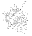
図1、図2、図3、図4及び図5において、本発明の一実施形態を採用した電動リール100は、外部電源から供給された電力により駆動されるとともに、手巻きの両軸受リールとして使用するときの電源を内部に有する小型の電動リールである。また、電動リール100は糸繰り出し長さ又は糸巻取長さに応じて仕掛けの水深を表示する水深表示機能を有するリールである。
<Overall configuration of electric reel>
1, FIG. 2, FIG. 3, FIG. 4 and FIG. 5, an
電動リールは、釣り竿に装着可能であり水深表示部4を有するリール本体1と、ハンドル2と、スプール10と、クラッチ操作部材11と、モータ12と、スプール駆動機構13(図5参照)と、クラッチ機構16(図4参照)と、を備える。また、電動リール100は、調整部材5と、検出子34(図4参照)と、位相検出部35(図4参照)と、リール制御部70(図14参照)と、をさらに備える。ハンドル2は、リール本体1に回転可能に設けられる。スプール10は、リール本体1に回転可能に設けられる。クラッチ操作部材11は、クラッチ機構16をオンオフ操作するためのものであり、リール本体1の後部に移動可能に設けられる。モータ12は、リール本体1に設けられ、スプール10を回転駆動する。クラッチ機構16は、ハンドル2の回転をスプール10に伝達可能なクラッチオン状態と、ハンドル2の回転をスプール10に伝達不能なクラッチオフ状態と、にクラッチ操作部材11の操作によって切換可能である。調整部材5は、リール本体1に回動可能に設けられる。調整部材5は、回動位置に応じてモータ12の出力を調整するための部材である。検出子34は、調整部材5に設けられ、調整部材5の回動位置を検出するために設けられる。位相検出部35は、検出子34の位相検出部35に対する相対的な回転位相を検出可能である。スプール駆動機構13は、ハンドル2及びモータ12の駆動力に応じてスプール10を駆動する。リール制御部70は、モータ12の出力を調整部材5の回動位置に応じて複数段階に調整するモータ制御部の機能を有する。例えば、スプール10の回転速度が複数段階に調整される。また、例えば、釣り糸に作用する張力が複数の段階に調整される。リール制御部70は、水深表示部4を表示制御する表示制御機能も有する。
The electric reel can be mounted on a fishing rod and has a
<リール本体>
リール本体1は、フレーム7と、第1側カバー8aと、第2側カバー8bと、前カバー9と、前述した水深表示部4と、備える。フレーム7は、例えば合成樹脂又は金属製の一体形成された部材である。フレーム7は、第1側板7aと、第2側板7bと、第1側板7aと第2側板7bとを連結する第1連結部材7c、第2連結部材7d及び第3連結部材7eと、を有する。第2側板7bは、第1側板7bと左右方向(図4左右方向)に間隔を隔てて配置される。第1側カバー8aは、フレーム7のハンドル2装着側を覆う。第2側カバー8bは、フレーム7のハンドル2装着側と逆側を覆う。前カバー9は、フレーム7の前部を覆う。
<Reel body>
The
第1側板7aは、側板本体19aと、側板本体19aと間隔を隔てて配置され、各種の機構を装着するための機構装着板19bを有する。側板本体19aは、図5に示すように、ボス部19cを有する。ボス部19cには、ブッシュ65が回転不能に装着されている。機構装着板19bは、以下に示す各種の機構を装着するために設けられる。機構装着板19bは、側板本体19aの外側面にネジ止め固定されている。図4及び図5に示すように、側板本体19aと第1側カバー8aとの間に、スプール駆動機構13と、クラッチ機構16を制御するクラッチ制御機構20と、スプール10の糸繰り出し方向の回転を制動するドラグ機構23(図5参照)と、が設けられている。第1側カバー8aには、スプール10を制動するキャスティングコントロール機構21が設けられている。キャスティングコントロール機構21は、後述するスプール軸14の両端を押圧してスプール10を制動する機構である。
The
第1側板7aと第2側板7bとの間には、スプール10と、クラッチ機構16と、スプール10に釣り糸を均一に巻き付けるためのレベルワインド機構22と、が設けられている。レベルワインド機構22は、図10に示すように、交差する螺旋状溝が形成されたトラバースカム軸63と、トラバースカム軸63の回転によってスプール10の前方でスプール軸14と平行な軸方向に往復移動する釣り糸ガイド64と、を有する。トラバースカム軸63のハンドル2側の端部は、図5に示すように、ブッシュ65を介してボス部19cに回転自在に支持される。
Between the
第2側板7bには、図4に示すように、スプール10が通過可能な円形開口7fが形成されている。円形開口7fには、スプール10のスプール軸14の第1端(図4左端)を回転自在に支持するスプール支持部17が芯出しされて装着されている。スプール支持部17は、第1側板7aの外側面にネジ止め固定されている。スプール支持部17には、スプール軸14の第1端を支持する第1軸受18aが収納される。
As shown in FIG. 4, a
第1連結部材7cは、第1側板7a及び第2側板7bの下部を連結する。第2連結部材7dはスプール10の前部を連結する。第1連結部材7cは、板状の部分であり、その左右方向の略中央部分に釣り竿に取り付けるための釣り竿装着部7gが一体形成されている。なお、釣り竿装着部7gは、フレーム7と別体であってもよい。第2連結部材7dは、概ね円筒状の部分であり、その内部にモータ12(図2及び図10参照)が収容されている。第3連結部材7eは、リール本体1の後部を連結する円弧状に湾曲した概ね板状の部分である。
The first connecting
第1側カバー8aには、駆動軸30を回転自在に支持するための第1ボス部8cが外方に突出して形成されている。第1ボス部8cの後方には、スプール軸14の第2端を支持する第2ボス部8dが外方に突出して形成されている。
A
第2側カバー8bは、第2側板7bの外縁部に例えばネジ止めされている。第2側カバー8bの前部下面には、図3に示すように、電源ケーブル接続用のコネクタ15が下向きに装着されている。
The
ハンドル2は、第1側カバー8a側に設けられている。ハンドル2は、図1及び図2に示すように、ハンドルアーム2aと、ハンドルアーム2aの先端に装着されたハンドル把手2bと、を有している。ハンドル2は、第1側板7a側に装着される。ハンドル2は、リール本体1に回転自在に支持された駆動軸30に一体回転可能に連結される。
The
前カバー9は、第1側板7a及び第2側板7bの前部外側面の上下2箇所で、例えばネジ止め固定されている。前カバー9には、釣り糸通過用の横長の開口(図示せず)が形成されている。前カバー9は、水深表示部4の後述するケース部材36の前下面を覆う。
The
水深表示部4は、釣り糸の先端に装着可能な仕掛けの水深を表示可能である。水深表示部4は、図1及び図10に示すように、第1側板7a及び第2側板7bの上部に載置されるケース部材36を有する。ケース部材36は、第1側板7a及び第2側板7bの外側面にネジ止め固定される。水深表示部4は、表示操作を行うための複数(例えば3つ)の操作ボタンを有するスイッチ操作部6を有する。
The water
ケース部材36の内部には、図10に示すように、リール制御部70と、水深表示用の液晶ディスプレイからなる表示器72と、主回路基板74aと、副回路基板74bと、モータ駆動回路76と、が収納されている。リール制御部70は、例えば、マイクロコンピュータによって構成される。主回路基板74aには、表示器72と、リール制御部70と、モータ駆動回路76と、が搭載される。副回路基板74bには、位相検出部35が搭載される。副回路基板74bは、主回路基板74aと電気的に接続される。副回路基板74bは、主回路基板74aに対して直交してケース部材36の後部に配置される。
As shown in FIG. 10, the
ケース部材36は、両側がそれぞれ第1側板7a及び第2側板7bに沿って後方に延びている。図4に示すように、ケース部材36の第1側板7a側の後部には、下部が開口する基板収容空間36hが形成される。この基板収容空間36hに副回路基板74bが収容される。ケース部材36の第2側板7b側の後部は、第2側板7bの上部及び第2側カバー8bの上部を覆っている。
Both sides of the
<スプール>
スプール10は、スプール軸14に一体回転可能に装着されている。スプール10は、図4に示すように、筒状の糸巻胴部10aと、糸巻胴部10aの両側に一体形成された大径の第1フランジ部10b及び第2フランジ部10cと、を有している。第1フランジ部10bは、第1側板7a側に設けられ、第2フランジ部10cは第2側板7b側に設けられる。スプール軸14は、糸巻胴部10aの内周部に圧入等の適宜の固定手段により固定されている。
<Spool>
The
スプール軸14の第1端は、前述したようにスプール支持部17において第1軸受18aにより支持されている。スプール軸14の第2端(図4右端)は、第1側カバー8aの第2ボス部8dに第2軸受18bにより支持されている。
The first end of the
スプール軸14のスプール固定部分より第2軸受18b側には、クラッチ機構16を構成するクラッチピン16aが径方向を貫通して装着されている。
A
<クラッチ機構>
クラッチ機構16は、図4に示すように、クラッチピン16aと、ピニオンギア32の図3左側端面に径方向に沿って十字に凹んで形成されたクラッチ凹部16bと、を有している。ピニオンギア32は、クラッチ機構16を構成するとともに、スプール駆動機構13の後述する第1回転伝達機構24を構成している。ピニオンギア32は、スプール軸14方向に沿って、図4に示すクラッチオン位置とクラッチオン位置より図4右側のクラッチオフ位置との間で移動する。クラッチオン位置では、クラッチピン16aがクラッチ凹部16bに係合してピニオンギア32の回転がスプール軸14に伝達され、クラッチ機構16は、クラッチオン状態になる。このクラッチオン状態では、ピニオンギア32とスプール軸14とが一体回転可能になる。また、クラッチオフ位置では、クラッチ凹部16bがクラッチピン16aから離反してピニオンギア32の回転がスプール軸14に伝達されない。このため、クラッチ機構16は、クラッチオフ状態になり、スプール10は自由回転可能になる。
<Clutch mechanism>
As shown in FIG. 4, the
<クラッチ制御機構>
クラッチ制御機構20は、クラッチ操作部材11の図10に実線で示すクラッチオン位置と図10に二点鎖線で示すクラッチオフ位置との間の揺動によりクラッチ機構16をクラッチオン状態とクラッチオフ状態とに切り換えるために設けられる。クラッチ制御機構20は、図5に示すように、スプール軸14回りに第1位置と第2位置とに回動するクラッチカム40と、クラッチカム40係合するクラッチヨーク41と、クラッチカム40とクラッチ操作部材11とを連結するクラッチプレート42と、を有する。クラッチプレート42は、クラッチカム40と一体的に回動する。クラッチカム40は、機構装着板19bに回動自在に支持される。クラッチカム40は、回動によってクラッチヨーク41を移動させるための一対のカム部40aを有する。
<Clutch control mechanism>
The
クラッチヨーク41は、ピニオンギア32をスプール軸方向にクラッチオフ位置とクラッチオン位置に移動させるために設けられる。クラッチヨーク41は、クラッチカム40のカム部40aに係合するカム受け部(図示せず)と、ピニオンギア32に係合する円弧部41aを有し、クラッチカム40が第1位置から第2位置に回動すると、クラッチオン位置からスプール軸方向外方(図5右側)のクラッチオフ位置に移動する。これにより、ピニオンギア32が軸方向外方(図5右側)に移動し、ピニオンギア32とクラッチピン16aとの係合が解除され、クラッチ機構16がクラッチオフ状態になる。クラッチヨーク41は、機構装着板19bに装着された一対のガイド軸49によって軸方向に案内される。クラッチヨーク41は、ガイド軸49に装着された一対のコイルバネ44によってクラッチオン位置に向けて付勢される。したがって、クラッチカム40が第2位置から第1位置に回動すると、クラッチヨーク41は、クラッチオフ位置からクラッチオン位置に戻り、ピニオンギア32がクラッチオン位置に戻る。なお、クラッチカム40の第2位置から第1位置への復帰動作は、図示しないクラッチ戻し機構によって、クラッチオフ状態でのハンドル2の糸巻取方向に回転によっても実現される。
The
クラッチプレート42は、クラッチ操作部材11の揺動によってクラッチカム40を回動させるために設けられる。クラッチプレート42は、例えば金属板を折り曲げて形成される。クラッチプレート42は、クラッチカム40に係合する係合部42aと、係合部42aから径方向の延びた後にクラッチ操作部材11に向けて折れ曲がる装着部42bと、を有する。係合部42aは、クラッチカム40の回動に連動して回動する。装着部42bは、クラッチ操作部材11に固定される。
The
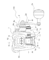
<クラッチ操作部材>
クラッチ操作部材11は、クラッチ機構16をクラッチオン状態とクラッチオフ状態とに切り換え操作するためのものである。クラッチ操作部材11は、図4に示すように、第1側板7aと第2側板7bとの間でリール本体1の後部に釣り竿装着部7gに対して接近及び離反する方向に移動可能に設けられる。この実施形態では、クラッチ操作部材11は、スプール10の軸回りに揺動可能に設けられる。クラッチ操作部材11は、図10に実線で示すクラッチオン位置と、二点鎖線で示すクラッチオフ位置と、の間で揺動する。第1側板7aの後部及び第2側板7bの後部の内側面には、図5に示すように、第1接触板43a及び第2接触板43bが各別に装着される。第1接触板43a及び第2接触板43bは、クラッチプレート42の装着部42bが貫通かつ揺動可能な円弧状の通過孔43cをそれぞれ有する。第1接触板43a及び第2接触板43bは、ポリアセタール等の摺動性が高い合成樹脂製の部材である。第1接触板43a及び第2接触板43bは、第1側板7a及び第2側板7bに各別に着脱可能に嵌め込まれている。クラッチ操作部材11は、両端部が第1接触板43a及び第2接触板43bに接触可能な長さを有する。
<Clutch operating member>
The
クラッチ操作部材11は、図7に示すように、第1側板7a側に設けられる第1操作部11aと、第2側板7b側に設けられる第2操作部11bと、第1操作部11aよりも釣り竿装着部7g側に設けられる第3操作部11cと、を有する。第1操作部11aは、第2操作部11bよりも釣り竿装着部7gから離れて設けられる。第1操作部11aは、図3に示すように、第1側板7aに向かって徐々に釣り竿装着部7gから離れる方向に傾斜して形成される。図10に示すように、第1操作部11aは、釣り竿装着部7gからの高さH1がスプール10の第1フランジ部10bに合うように少なくとも一部が配置される。第1操作部11aは、第1側板7aに向かって徐々に釣り竿装着部7gから離れる方向に傾斜して形成される。
As shown in FIG. 7, the
第2操作部11bは、釣り竿装着部7gからの高さH2が糸巻胴部10aに合うように少なくとも一部が配置される。具体的には、第2操作部11bは、釣り竿装着部7gからの高さH2が釣り竿装着部7gからの糸巻胴部10aの高さと少なくとも一部で等しくなるように形成される。第3操作部11cは、クラッチ機構16をクラッチオフ状態からクラッチオン状態に戻すときに用いられる。第3操作部11cは、図9に示すように、第1操作部11aよりもスプール10に向かって凹んで形成される。また、図8に示すように、第3操作部11cは、第1側板7aに接する部分には設けられていない。したがって、クラッチ操作部材11の第1側板7aに近い近接部11fは凹んでおらず滑らかに凸に湾曲している。これにより、第3操作部11cによって、指の引っ掛かりを確保してクラッチオン操作を行いやすくするとともに、クラッチ操作部材11の第1側板7aに近い近接部11fによって、凹んだ第3操作部11cをクラッチ操作部材11に設けても釣り糸がクラッチ操作部材11に引っ掛かりにくくなる。
The
第1操作部11aと第3操作部11cとの境界部分11eは、第1側板7aよりも後方に突出している。これにより、ハンドル2を操作する手の指によってクラッチオン操作を行うこともできる。
A
また、クラッチ操作部材11は、クラッチプレート42の装着部42bに固定される矩形断面の貫通孔11dを有する。貫通孔11dは、左右方向にクラッチ操作部材11を貫通して形成される。貫通孔11dは、クラッチプレート42の装着部42bの厚み及び幅と実質的に等しい矩形形状に形成される。装着部42bは、第1接触板43a、貫通孔11d及び第2接触板43bを貫通して配置される。これより、クラッチ操作部材11が装着部42bに固定される。
The
<スプール駆動機構>
スプール駆動機構13は、スプール10を糸巻取方向に駆動する。また、巻取時にスプール10にドラグ力を発生させて釣り糸の切断を防止する。スプール駆動機構13は、図11に示すように、図示しないローラクラッチの形態の逆転防止部によって糸巻取方向の回転が禁止されたモータ12と、第1回転伝達機構24と、第2回転伝達機構25と、を備えている。第1回転伝達機構24は、モータ12の回転を減速してスプール10に伝達する。第2回転伝達機構25は、ハンドル2の回転を、第1回転伝達機構24を介して増速してスプール10に伝達する。
<Spool drive mechanism>
The
第1回転伝達機構24は、図11に示すように、モータ12の出力軸に連結された図示しない遊星減速機構を有する。遊星減速機構のケース26の内側面には、図示しない内歯ギアが形成され、内歯ギアの出力がケース26の外周面に形成された第1ギア部材60によってスプール10に伝達される。具体的には、第1回転伝達機構24は、第1ギア部材60と、第1ギア部材60に噛み合う第2ギア部材61と、第2ギア部材61に噛み合うピニオンギア32と、をさらに有する。第2ギア部材61及びピニオンギア32は、図5に示すように、機構装着板19bと側板本体19aとの外側面との間に配置されている。第2ギア部材61は、第1ギア部材60の回転をピニオンギア32に回転方向を整合させて伝達するための中間ギアである。第2ギア部材61は、側板本体19aのボス部19c及び機構装着板19bに転がり軸受を介して回転自在に支持されている。図5及び図11に示すように、第2ギア部材61には、トラバースカム軸63が一体回転可能に連結されている。トラバースカム軸63の第1側板7a側の端部には、非円形部63aが形成され、第2ギア部材61は、非円形部63aに係合してトラバースカム軸63を回転させる。
As shown in FIG. 11, the first
ピニオンギア32は、側板本体19aに装着された第3軸受18cにより第2側板7bにスプール軸14回りに回転自在かつ軸方向移動自在に装着されている。ピニオンギア32は、クラッチ制御機構20により制御されて軸方向にクラッチオン位置とクラッチオフ位置との間でスプール軸14の外周側を移動する。ピニオンギア32は、クラッチヨーク41に係合してスプール軸14方向に移動する。
The
第2回転伝達機構25は、図5及び図11に示すように、ハンドル2が一体回転可能に連結された駆動軸30と、駆動ギア31と、第3ギア部材62と、ドラグ機構23と、を有している。
As shown in FIGS. 5 and 11, the second
駆動軸30は、図5に示すように、機構装着板19b及び第1側カバー8aの第1ボス部8cに回転自在に支持されている。駆動軸30は、ローラ型のワンウェイクラッチ37により第2側カバー8bの第1ボス部8cに支持されている。駆動軸30は、ワンウェイクラッチ37により糸繰り出し方向の回転が禁止されている。駆動ギア31は、駆動軸30に回転自在に装着されている。駆動ギア31は、ドラグ機構23により糸繰り出し方向の回転が制動される。これにより、スプール10の糸繰り出し方向の回転が制動される。
As shown in FIG. 5, the
第3ギア部材62は、ハンドル2の回転をスプール10に伝達するために設けられている。第3ギア部材62は、遊星減速機構のキャリアに一体回転可能に連結されている。第3ギア部材62は、駆動ギア31に噛み合い、ハンドル2の回転を遊星減速機構のキャリアに伝達する。キャリアに伝達された回転は、第1ギア部材60及び第2ギア部材61を介してピニオンギア32に伝達される。第3ギア部材62から第2ギア部材61までの減速比は概ね「1」である。
The
ドラグ機構23は、図5に示すように、ワンウェイクラッチ37の内輪37aに一体回転可能に連結されかつ内輪37aによって押圧されるドラグ板38を有する。ドラグ板38は、駆動軸30に一体回転可能に連結される。ドラグ板38は、ドラグ座金39を介して駆動ギア31を押圧する。ドラグ機構23の制動力(ドラグ板38を押圧する押圧力)は、駆動軸30に螺合するスタードラグ3によって調整される。
As shown in FIG. 5, the
<調整部材>
調整部材5は、モータ12の出力を複数段階(例えば、10段階以上であり、この実施形態では、31段階)に調整するためにリール本体1に設けられる。調整部材5は、図2に示すように、第1側板7aの側板本体19aと第1側カバー8aとの間に設けられる。この実施形態では、図4及び図6に示すように、調整部材5は、水深表示部4のケース部材36の後部の外側面に立設された支持軸36aに回動自在に装着される。調整部材5は、支持軸36aに装着された状態で第1側板7aと第1側カバー8aの間に配置される。
<Adjustment member>
The
支持軸36aは、基端側のテーパ面36bと、テーパ面36bに連なる支持面36cと、支持面36cよりも小径の部材装着部36dと、を有する。また、支持軸36aは、先端面に雌ネジ穴36eを有する。支持軸36aの周囲において、ケース部材36の外側面には、一対の円弧凹部36fと、一対の係合凹部36gと、が180°間隔を隔てて形成されている。係合凹部36gは、球状に凹んで形成され、円弧凹部36fと隣接して配置される。係合凹部36gは、調整部材5によってモータ12を停止させる操作開始位置に対応して設けられる。円弧凹部36fは、調整部材5の回動中心と同芯の円弧で形成され、調整部材5の回動角度に対応して設けられる。調整部材5の回動角度は、この実施形態では、例えば、80°から120°の範囲である。この実施形態では、回動角度は100°である。ただし、調整部材5の回動角度は、これに限定されない。
The
調整部材5の回動角度が大きい方がモータ12の出力調整の1段階ごとに割り振ることができる角度が大きくなるため、出力の調整操作を各段階で安定して行える。しかし、調整部材5の回動角度を大きくし過ぎると、複数段階にわたる操作を迅速に行いにくい。また、リール本体の形状によっては回動角度を大きくできない場合がある。これらの制約の中で最大限の角度に調整部材5の回動角度を設定するのが好ましい。
When the rotation angle of the adjusting
調整部材5は、例えば合成樹脂製の概ね環状の部材である。調整部材5は、図6に示すように、外周面に径方向に突出する操作突起5aを有する。操作突起5aを除く調整部材5の外周面には、滑り止めのための軸方向に沿った多数の溝5bが周方向に間隔を隔てて形成される。調整部材5の外側面には、調整部材5の回動範囲を規制するための規制突起5cが軸方向に突出して形成される。第1側カバー8aは、調整部材5を第1側カバー8aよりも突出させるための平面視矩形形状の開口8eを有している。規制突起5cは、開口8eの内側面に接触して調整部材5の回動範囲を規制する。
The
図12に示すように、調整部材5のケース部材36と対向する内側面には、検出子34を収容する一対の検出子収容部5dと、調整部材5を操作開始位置に位置決めするための一対の位置決め部45を収容する一対の位置決め収容部5eと、が周方向に間隔を隔てて形成される。一対の検出子収容部5dと、一対の位置決め収容部5eは、それぞれ180°間隔で円形に凹んで形成される。
As shown in FIG. 12, on the inner surface of the
位置決め部45は、図6に示すように、一対の位置決め収容部5eに進退自在に装着される一対の位置決めピン45aと、一対の位置決めピン45aをケース部材36に向けて付勢する一対のコイルバネ45bと、を有している。コイルバネ45bは、位置決め収容部5eに収容される。位置決めピン45aは半球形状の頭部45cを有し、頭部45cが係合凹部36g及び円弧凹部36fに係合する。この位置決め部45を設けることにより、調整部材5が操作開始位置に確実に位置決めできる。
As shown in FIG. 6, the positioning
調整部材5の中心部には、図4に示すように、支持軸36aに回動自在に支持される被支持孔5fと、被支持孔5fよりも大径の装着孔5gと、装着孔5gよりも大径の座繰り孔5hとが内側面から外側面に向かって形成される。被支持孔5fは、内側面側が支持軸36aのテーパ面36bに沿ったテーパ形状である。装着孔5gと支持軸36aの部材装着部36dとの間には両者に接触する回動規制部材46が装着されている。回動規制部材46は、例えばOリング等の環状弾性部材によって構成される。この回動規制部材46によって調整部材5の回動を規制する。これにより、釣り人が調整部材5を操作した位置に調整部材5を保持できる。回動規制部材46及び調整部材5は、座繰り孔5hに配置された座金部材47によって抜け止めされる。座金部材47は、支持軸36aの雌ネジ穴36eに螺合する固定ボルト48によって抜け止めされる。これにより、調整部材5がケース部材36に回動自在に装着される。なお、座繰り孔5hは、第1側カバー8aによって覆われる。したがって、調整部材5の外周部分だけが第1側カバー8aの開口8eから突出し、調整部材5のその他の部分は、第1側カバー8a及びケース部材36によってカバーされる。
As shown in FIG. 4, the
<検出子>
検出子34は、図4、図6及び図12に示すように、調整部材5に装着される。具体的には、前述したように調整部材5の一対の検出子収容部5dに接着等の適宜の固定手段によって固定される。検出子34は、一対の検出子収容部5dに各別に固定される第1磁石34aと第2磁石34bとを有する。第1磁石34a及び第2磁石34bは、それぞれ調整部材5の軸方向に沿って着磁される。第2磁石34bは、第1磁石34aと逆方向に着磁される。この実施形態では、第1磁石34aは、ケース部材36に対向する側がN極に着磁され、検出子収容部5dの底面側がS極に着磁される。反対に第2磁石は、ケース部材36に対向する側がS極に着磁され、検出子収容部5dの底面側がN極に着磁される。このように軸方向着磁の第1磁石34aと第2磁石34bを磁束方向が逆になるように配置することによって、径方向着磁の磁石と同じに反応する検出子34を、軸方向着磁の簡素な第1磁石34a及び第2磁石34bによって得ることができる。
<Detector>
As shown in FIGS. 4, 6 and 12, the
<位相検出部>
位相検出部35は、前述したように水深表示部4のケース部材36の内部に配置された副回路基板74bに搭載されるホール素子35aである。ホール素子35aは、図10に示すように、調整部材5の回転中心Cに合わせて配置される。このようにホール素子35aを配置することによって、第1磁石34aと第2磁石34bとによって生じる磁束方向の変化をホール素子35aが検出可能になる。この結果、ホール素子35aを用いて、調整部材5の回動によって変化する磁束方向を検出して調整部材5の回転位相を検出できる。ホール素子35aは、図13に示すように、径方向着磁の検出子34のN極がホール素子35aに例えば半円形で表示されたマーク35b側にあるときを0°とすると、検出子34が0°の位置において、図14に示すように出力電圧が最小になる。検出子34が0°から反時計回りにホール素子35aに対して相対回転すると、出力電圧が徐々に上昇し、360°に近づくと出力電圧が最大になり、0°に戻るとまた最小にもどる。これにより、0°から360°までの範囲で調整部材5の回転位相をホール素子35aによって検出できる。ただし、この実施形態では、例えば、50°から150°程度の範囲でホール素子35aの出力電圧を用いている。ただし、ホール素子35aの出力電圧の角度範囲は、これに限定されない。例えば、230°から330°の範囲等、ホール素子の出力特性に応じて適宜選択可能である。
<Phase detector>
As described above, the
<制御系>
電動リール100は、図15に示すように、モータ12及び表示器72を制御するリール制御部70を有する。リール制御部70は、CPU(中央演算ユニット)を含むマイクロコンピュータによって構成される。リール制御部70には、位相検出部35としてのホール素子35aと、スイッチ操作部6の各スイッチと、スプールセンサ78とが接続されている。また、リール制御部70には制御対象としての表示器72と、モータ駆動回路76と、ブザー80と、他の入出力部82と、が接続されている。スプールセンサ78は、スプール10に装着された図示しない磁石を検出する一対のリードスイッチを有する。一対のリードスイッチはスプール10の回転方向に並べて配置されている。この実施形態では、一対のリードスイッチは、リール本体1のスプール支持部17に設けられる。スプールセンサ78によって、スプール10の回転数(回転位置)及び回転方向を検出できる。モータ駆動回路76は、モータ12をPWM(パルス幅変調)駆動する。すなわち、デューティ比を変化させてモータ12を駆動する。ブザー80は、ケース部材36の内部に収納される。ブザー80は仕掛けが棚位置に到達したり、海底に到達したりすると鳴動する。他の入出力部82は、例えば無線通信部などから構成される。無線通信部は、外部の表示装置と水深データ等の各種のデータを双方向に通信可能である。
<Control system>
As shown in FIG. 15, the
<電動リールの操作>
このように構成された電動リール100では、釣りを行うときは、釣り人は釣り竿を持つ手の親指によってクラッチ操作部材11の例えば第2操作部11bを押し下げ操作する。これにより、クラッチ機構16がクラッチオン状態からクラッチオフ状態に切り換わり、スプール10が自由回転状態になる。そして、仕掛けの自重によって釣り糸を繰り出し、仕掛けを魚が群れる棚位置まで下ろす。このとき、スプール10の第1フランジ部10bをクラッチ操作した親指の先でサミング操作する場合、第2操作部11bから第1操作部11aに向けて親指を伸ばす。すると、第1操作部11aに釣り竿装着部7gからの高さが徐々に高くなる傾斜面があり、かつ第1操作部11aの高さH1が第1フランジ部10bの高さに応じて設定されているため、親指の先が容易に第1フランジ部10bに到達する。このように、クラッチ操作部材11が第1フランジ部10bに対応する高さH1に配置された第1操作部11aを有するため、サミング操作を行いやすくなる。
<Operation of electric reel>
In the
仕掛けに魚が掛かって釣り糸を巻きとるときには、釣り竿を持つ手の親指の先でクラッチ操作部材11の第3操作部11cを押し上げ操作する。このとき、第3操作部11cが凹んで形成されているので、指先が第3操作部11cに引っ掛かりやすくなり、クラッチ操作部材11の押し上げ操作を行いやすい。クラッチ操作部材11を押し上げ操作すると、クラッチ機構16がクラッチオン状態に切り換わり、ハンドル2及びモータ12によってスプール10を糸巻取方向に回転させることができる。
When a fish is hooked on the device and the fishing line is wound up, the
モータ12により釣り糸を巻きとるときには、釣り竿を持つ手またはハンドル2を操作する手で調整部材5を操作する。このとき、調整部材が第1側板7aと第1側カバー8aの間に配置されているため、リール本体1の後部に配置されたクラッチ操作部材11と調整部材5とが近くに配置される。このため、サミング操作して手の指先で調整部材5を操作できる。このため、調整部材5とクラッチ操作部材11とを連携して操作しやすくなる。また、キャスティングが進行して釣り糸の巻き付け量が少なくなると、第2操作部11bを介してサミング操作を行えるので、キャスティング中のサミング操作を釣り糸の巻き付け量にかかわらず安定して行える。
When winding the fishing line with the
調整部材5を回動操作すると、検出子34が調整部材5とともに回動し、位相検出部35ホール素子35aの出力電圧が変化する。この出力電圧の変化によってリール制御部70は、モータ駆動回路76を制御して、モータ12の出力を調整部材5の回動位置に応じて調整する。このとき、調整部材5の回転位相をロータリーエンコーダ又はポテンショメータ等の回転検出器を用いずに検出しているので、調整部材5が調整する10段階以上に多くなっても、調整部材5の取付部分の体積の増加を低コストで抑えることができるようになる。
When the
<他の実施形態>
以上、本発明の一実施形態について説明したが、本発明は上記実施形態に限定されるものではなく、発明の要旨を逸脱しない範囲で種々の変更が可能である。
<Other embodiments>
As mentioned above, although one Embodiment of this invention was described, this invention is not limited to the said embodiment, A various change is possible in the range which does not deviate from the summary of invention.
(a)前記実施形態では、クラッチ操作部材11を第1側板7a及び第2側板7bで両端支持したが、本発明はこれに限定されない。クラッチ操作部材を第1側板側に片持ち支持してもよい。
(A) Although the
(b)前記実施形態では、クラッチ操作部材11がスプール軸14回りに揺動したが、クラッチ操作部材は、釣り竿装着部と接近及び離反する方向に移動するものであればどのように移動させてもよい。例えば、クラッチ操作部材11がスプール軸と別の軸回りに揺動させてもよく、また、上下に直線的に移動するようにしてもよい。
(B) In the above embodiment, the
(c)前記実施形態では、第1操作部11a及び第2操作部11bを、それぞれ釣り竿装着部7gからの高さが徐々に高くなるように傾けて配置したが、本発明はこれに限定されない。特に、第2操作部11bは、スプール10の糸巻胴部10aの釣り竿装着部7gからの高さに対応して同じ高さであってもよい。
(C) In the above-described embodiment, the
(d)前記実施形態では、両軸受リールとして電動リールを例示したが、通常の手巻きの両軸受リールにも本発明を適用できる。 (D) In the above embodiment, the electric reel is exemplified as the dual-bearing reel, but the present invention can also be applied to a normal manual-winding dual-bearing reel.
<特徴>
上記実施形態は、下記のように表現可能である。
<Features>
The above embodiment can be expressed as follows.
(A)両軸受リールの一例としての電動リール100は、釣り糸を前方に繰り出すリールである。電動リール100は、リール本体1と、ハンドル2と、糸巻用のスプール10と、クラッチ機構16と、クラッチ操作部材11と、を備える。リール本体1は、第1側板7a及び第1側板7aと左右方向に間隔を隔てて配置される第2側板7bを有するフレーム7と、フレーム7に設けられる釣り竿装着部7gと、を有する。ハンドルは、リール本体1の第1側板7a側に回転自在に装着される。スプール10は、リール本体1に回転可能に設けられる。クラッチ機構16は、ハンドル2の回転をスプール10に伝達可能なクラッチオン状態と、ハンドル2の回転をスプール10に伝達不能なクラッチオフ状態と、に切換可能である。クラッチ操作部材11は、第1側板7aと第2側板7bとの間でリール本体1の後部に釣り竿装着部7gに対して接近及び離反する方向に移動可能に設けられる。クラッチ操作部材11は、クラッチ機構16をクラッチオン状態とクラッチオフ状態とに切り換え操作するための部材である。クラッチ操作部材11は、第1側板7a側に設けられる第1操作部11aと、第2側板7b側に設けられる第2操作部11bと、第1操作部11aよりも釣り竿装着部7g側に設けられる第3操作部11cと、を有する。第1操作部11aは、第2操作部11bよりも釣り竿装着部7gから離れて設けられる。第3操作部11cは、クラッチオフ状態からクラッチオン状態にクラッチ機構16を戻すときに用いられる。
(A) An
この電動リール100では、クラッチ機構16をクラッチオン状態からクラッチオフ状態にするときには、クラッチ操作部材11の第1操作部11a又は第2操作部11bを釣り竿装着部7gに近づく方向に操作する。また、クラッチ機構16をクラッチオフ状態からクラッチオン状態にするときには、第3操作部11cを釣り竿装着部7gから離れる方向に操作する。ここでは、第1操作部11aよりも釣り竿装着部7gに近い位置に第3操作部11cが設けられる。これにより、第2操作部11bを用いてクラッチオフ操作したことにより、第3操作部11cが釣り竿装着部7gに近づいても、第2操作部11bを操作した指で第3操作部11cを操作することができる。このため、クラッチオン状態への切換操作を容易に行えるようになる。しかも、第1操作部11aが第2操作部11bよりも釣り竿装着部7gから離れて設けられるため、第1操作部11aを用いてクラッチオフ操作を行うと、第1操作部11aを操作した指の指先をスプール10の第1フランジ部10bに接触させやすくなり、釣り人がサミング操作を行いやすくなる。
In the
(B)電動リール100において、第3操作部11cは、第1操作部11aよりもスプール10に向かって凹んで形成される。この場合には、第3操作部11cが第1操作部11aよりもスプール10に向かって凹んで形成されるので、第3操作部11cを釣り竿装着部7gから離れる方向に操作してクラッチオン状態に戻すとき、ハンドル2を操作する手と反対側の手の指先で第3操作部11cを操作しやすくなる。
(B) In the
(C)電動リール100において、クラッチ操作部材11は、スプール10の回転軸であるスプール軸14回りに揺動する。この場合には、クラッチ操作部材11の揺動軸芯がクラッチ操作部材11から大きく離れるため、クラッチ操作部材11が揺動してもその傾きの変化が小さくなる。このため、第3操作部11cを用いてクラッチオフ状態からクラッチオン状態への切換操作をさらに容易におこなえる。
(C) In the
(D)電動リール100において、スプール10は、釣り糸巻き付け用の糸巻胴部10aと、糸巻胴部10aの両端に大径に設けられる第1フランジ部10b及び第2フランジ部10cと、を有する。第1操作部11aは、釣り竿装着部7gからの高さH1が第1フランジ部10bに合うように配置され、第2操作部11bは、釣り竿装着部7gからの高さH2が糸巻胴部10aに合うように配置される。この場合には、キャスティング当初の釣り糸のスプール10への巻き付け量が多い場合は、第1操作部11aを介して第1フランジ部10bに対してサミング操作を行い、キャスティングが進行して釣り糸の巻き付け量が少なくなると、第2操作部11bを介して糸巻胴部10a上の釣り糸に対してサミング操作を行えるので、キャスティング中のサミング操作を釣り糸の巻き付け量にかかわらず安定して行える。
(D) In the
(E)電動リール100において、第1操作部11aは、第1側板7aに向かって徐々に釣り竿装着部7gから離れる方向に傾斜して形成される。この場合には、第1操作部11aの釣り竿装着部7gからの高さが第1側板7aに近づくに連れて徐々に高くなるので、さらにサミングをする指を第1操作部11aに置くだけで、指先が第1フランジ部10bに近づく。このため、サミング操作をさらに行いやすくなる。
(E) In the
(F)電動リール100において、第2操作部11bは、釣り竿装着部7gからの高さが釣り竿装着部7gから糸巻胴部までの高さH2と少なくとも一部で等しくなるように形成される。この場合には、第2操作部11bを操作してクラッチオン状態からクラッチオフ状態に操作しやすくなるとともに、糸巻き量が少ないときにサミング操作を行いやすい。
(F) In the
(G)電動リール100において、第1操作部と第3操作部との境界部分は、第1側板よりも後方に突出して配置される。この場合には、ハンドルを操作する手の指でもクラッチ操作を行うことができる。
(G) In the
(H)電動リール100において、リール本体1は、釣り糸の先端に装着される仕掛けの水深を表示するため水深表示部4をさらに備える。この場合には、いわゆるカウンタと呼ばれる水深表示部4を有する電動リールにおいて、クラッチオフ状態からクラッチオン状態への切換操作を容易に行えるようになる。
(H) In the
(I)電動リール100において、スプール10を回転駆動するモータ12をさらに備える。この場合には、モータ12によってスプールを回転駆動する電動リールにおいて、クラッチオフ状態からクラッチオン状態への切換操作を容易に行えるようになる。
(I) The
1 リール本体
2 ハンドル
4 水深表示部
7 フレーム
7a 第1側板
7b 第2側板
7g 釣り竿装着部
8a 第1側カバー
8b 第2側カバー
10 スプール
10a 糸巻胴部
10b 第1フランジ部
11 クラッチ操作部材
11a 第1操作部
11b 第2操作部
11c 第3操作部
11e 境界部分
11f 近接部
12 モータ
14 スプール軸
16 クラッチ機構
DESCRIPTION OF
Claims (9)
第1側板及び前記第1側板と左右方向に間隔を隔てて配置される第2側板を有するフレームと、前記フレームに設けられる釣り竿装着部と、を有するリール本体と、
前記リール本体の前記第1側板側に装着されるハンドルと、
前記リール本体に回転可能に設けられる糸巻用のスプールと、
前記ハンドルの回転を前記スプールに伝達可能なクラッチオン状態と、前記回転を前記スプールに伝達不能なクラッチオフ状態と、に切換可能なクラッチ機構と、
前記第1側板と前記第2側板との間で前記リール本体の後部に前記釣り竿装着部に対して接近及び離反する方向に移動可能に設けられ、前記クラッチ機構を前記クラッチオン状態と前記クラッチオフ状態とに切り換え操作するためのクラッチ操作部材と、を備え、
前記クラッチ操作部材は、前記第1側板側に設けられる第1操作部と、前記第2側板側に設けられる第2操作部と、前記第1操作部よりも前記釣り竿装着部側に設けられる第3操作部と、を有し、前記第1操作部は、前記第2操作部よりも前記釣り竿装着部から離れて設けられ、かつ前記第3操作部は、前記クラッチオフ状態から前記クラッチオン状態に前記クラッチ機構を戻すときに用いられる、両軸受リール。 A dual-bearing reel that feeds the fishing line forward,
A reel body having a frame having a first side plate and a second side plate arranged at a distance from the first side plate in the left-right direction, and a fishing rod mounting portion provided on the frame;
A handle mounted on the first side plate side of the reel body;
A spool for spooling rotatably provided on the reel body;
A clutch mechanism capable of switching between a clutch-on state in which the rotation of the handle can be transmitted to the spool and a clutch-off state in which the rotation cannot be transmitted to the spool;
A rear portion of the reel body is provided between the first side plate and the second side plate so as to be movable toward and away from the fishing rod mounting portion, and the clutch mechanism is in the clutch-on state and the clutch-off state. A clutch operating member for switching to a state,
The clutch operating member includes a first operating portion provided on the first side plate side, a second operating portion provided on the second side plate side, and a first operating portion provided closer to the fishing rod mounting portion than the first operating portion. Three operating parts, the first operating part is provided farther from the fishing rod mounting part than the second operating part, and the third operating part is moved from the clutch-off state to the clutch-on state. A double-bearing reel used for returning the clutch mechanism to
前記第1操作部は、前記釣り竿装着部からの高さが前記フランジ部に合うように少なくとも一部が配置され、前記第2操作部は、前記釣り竿装着部からの高さが前記糸巻胴部に合うように少なくとも一部が配置される、請求項1から3のいずれか1項に記載の両軸受リール。 The spool has a bobbin trunk for fishing line winding, and a pair of flange portions provided at large diameters at both ends of the bobbin trunk,
The first operation portion is at least partially arranged so that the height from the fishing rod mounting portion matches the flange portion, and the second operation portion has a height from the fishing rod mounting portion that is the bobbin trunk portion. The dual-bearing reel according to any one of claims 1 to 3, wherein at least a part of the reel is arranged so as to meet the requirements.
Priority Applications (4)
| Application Number | Priority Date | Filing Date | Title |
|---|---|---|---|
| JP2012253053A JP2014100078A (en) | 2012-11-19 | 2012-11-19 | Double bearing reel |
| KR1020130078484A KR20140064604A (en) | 2012-11-19 | 2013-07-04 | Dual bearing reel |
| TW102127664A TWI583306B (en) | 2012-11-19 | 2013-08-01 | Double bearing type reel |
| CN201310580624.0A CN103814873A (en) | 2012-11-19 | 2013-11-19 | Dual-bearing reel |
Applications Claiming Priority (1)
| Application Number | Priority Date | Filing Date | Title |
|---|---|---|---|
| JP2012253053A JP2014100078A (en) | 2012-11-19 | 2012-11-19 | Double bearing reel |
Publications (2)
| Publication Number | Publication Date |
|---|---|
| JP2014100078A true JP2014100078A (en) | 2014-06-05 |
| JP2014100078A5 JP2014100078A5 (en) | 2016-01-14 |
Family
ID=50750406
Family Applications (1)
| Application Number | Title | Priority Date | Filing Date |
|---|---|---|---|
| JP2012253053A Pending JP2014100078A (en) | 2012-11-19 | 2012-11-19 | Double bearing reel |
Country Status (4)
| Country | Link |
|---|---|
| JP (1) | JP2014100078A (en) |
| KR (1) | KR20140064604A (en) |
| CN (1) | CN103814873A (en) |
| TW (1) | TWI583306B (en) |
Cited By (5)
| Publication number | Priority date | Publication date | Assignee | Title |
|---|---|---|---|---|
| KR20160088219A (en) | 2015-01-15 | 2016-07-25 | 가부시키가이샤 시마노 | Electrical fishing reel |
| KR20160104550A (en) | 2015-02-26 | 2016-09-05 | 가부시키가이샤 시마노 | Dual-bearing reel |
| KR20160140356A (en) * | 2015-05-28 | 2016-12-07 | 가부시키가이샤 시마노 | Dual-bearing fishing reel |
| JP2018038390A (en) * | 2016-09-02 | 2018-03-15 | 株式会社シマノ | Electric reel |
| JP7114538B2 (en) | 2019-09-17 | 2022-08-08 | 太平洋工業株式会社 | Electric reel and electric reel control device |
Families Citing this family (5)
| Publication number | Priority date | Publication date | Assignee | Title |
|---|---|---|---|---|
| JP6376848B2 (en) * | 2014-06-03 | 2018-08-22 | 株式会社シマノ | Double-bearing reel clutch return mechanism |
| JP6560903B2 (en) * | 2015-05-27 | 2019-08-14 | 株式会社シマノ | Double bearing reel |
| JP6836324B2 (en) * | 2016-01-26 | 2021-02-24 | 株式会社シマノ | Electric reel |
| JP2017221112A (en) * | 2016-06-13 | 2017-12-21 | 株式会社東和電機製作所 | Pole-and-line fishing machine |
| JP6986865B2 (en) * | 2017-06-07 | 2021-12-22 | 株式会社シマノ | Electric reel |
Citations (4)
| Publication number | Priority date | Publication date | Assignee | Title |
|---|---|---|---|---|
| US4142694A (en) * | 1972-12-13 | 1979-03-06 | Rankin Jr Marvin L | Bait casting fishing reel |
| JP2001204321A (en) * | 2000-01-31 | 2001-07-31 | Shimano Inc | Double bearing reel and clutch operation assistance member |
| JP2005013114A (en) * | 2003-06-26 | 2005-01-20 | Shimano Inc | Double bearing reel |
| JP2012065574A (en) * | 2010-09-22 | 2012-04-05 | Shimano Inc | Dual-bearing reel clutch control device |
Family Cites Families (13)
| Publication number | Priority date | Publication date | Assignee | Title |
|---|---|---|---|---|
| JPH04106979U (en) * | 1991-02-22 | 1992-09-16 | 株式会社シマノ | fishing reel |
| JP2957882B2 (en) * | 1994-02-22 | 1999-10-06 | ダイワ精工株式会社 | Fishing reel |
| JP3156906B2 (en) * | 1995-05-19 | 2001-04-16 | ダイワ精工株式会社 | Double bearing type reel for fishing |
| JP3325188B2 (en) * | 1996-09-10 | 2002-09-17 | ダイワ精工株式会社 | Double bearing reel for fishing |
| JP3472083B2 (en) * | 1997-06-11 | 2003-12-02 | ダイワ精工株式会社 | Double bearing type reel for fishing |
| JPH11113461A (en) * | 1997-10-09 | 1999-04-27 | Shimano Inc | Double bearing reel |
| SG80003A1 (en) * | 1997-12-10 | 2001-04-17 | Shimano Kk | Mechanical assembly with incompatible metallic materials |
| JPH11308950A (en) * | 1998-04-27 | 1999-11-09 | Ryobi Ltd | Double bearing reel for fishing |
| JP3515017B2 (en) * | 1999-07-15 | 2004-04-05 | ダイワ精工株式会社 | Double bearing reel for fishing |
| JP2001333673A (en) * | 2000-05-31 | 2001-12-04 | Shimano Inc | Counter case of fishing reel |
| SG114615A1 (en) * | 2002-05-09 | 2005-09-28 | Shimano Kk | Handle assembly for fishing reel |
| JP4963279B2 (en) * | 2007-08-06 | 2012-06-27 | 株式会社シマノ | Clutch operating member for dual-bearing reel |
| JP2011004714A (en) * | 2009-06-29 | 2011-01-13 | Globeride Inc | Fishing reel |
-
2012
- 2012-11-19 JP JP2012253053A patent/JP2014100078A/en active Pending
-
2013
- 2013-07-04 KR KR1020130078484A patent/KR20140064604A/en not_active Application Discontinuation
- 2013-08-01 TW TW102127664A patent/TWI583306B/en active
- 2013-11-19 CN CN201310580624.0A patent/CN103814873A/en active Pending
Patent Citations (4)
| Publication number | Priority date | Publication date | Assignee | Title |
|---|---|---|---|---|
| US4142694A (en) * | 1972-12-13 | 1979-03-06 | Rankin Jr Marvin L | Bait casting fishing reel |
| JP2001204321A (en) * | 2000-01-31 | 2001-07-31 | Shimano Inc | Double bearing reel and clutch operation assistance member |
| JP2005013114A (en) * | 2003-06-26 | 2005-01-20 | Shimano Inc | Double bearing reel |
| JP2012065574A (en) * | 2010-09-22 | 2012-04-05 | Shimano Inc | Dual-bearing reel clutch control device |
Cited By (12)
| Publication number | Priority date | Publication date | Assignee | Title |
|---|---|---|---|---|
| KR20160088219A (en) | 2015-01-15 | 2016-07-25 | 가부시키가이샤 시마노 | Electrical fishing reel |
| KR20160104550A (en) | 2015-02-26 | 2016-09-05 | 가부시키가이샤 시마노 | Dual-bearing reel |
| JP2016158509A (en) * | 2015-02-26 | 2016-09-05 | 株式会社シマノ | Double bearing reel |
| CN105918269A (en) * | 2015-02-26 | 2016-09-07 | 株式会社岛野 | Dual-bearing Reel |
| US10028495B2 (en) | 2015-02-26 | 2018-07-24 | Shimano Inc. | Dual-bearing reel |
| CN105918269B (en) * | 2015-02-26 | 2021-06-25 | 株式会社岛野 | Dual-bearing reel |
| KR20160140356A (en) * | 2015-05-28 | 2016-12-07 | 가부시키가이샤 시마노 | Dual-bearing fishing reel |
| JP2016220570A (en) * | 2015-05-28 | 2016-12-28 | 株式会社シマノ | Double bearing reel |
| TWI682714B (en) * | 2015-05-28 | 2020-01-21 | 日商島野股份有限公司 | Double bearing reel |
| KR102577102B1 (en) | 2015-05-28 | 2023-09-11 | 가부시키가이샤 시마노 | Dual-bearing fishing reel |
| JP2018038390A (en) * | 2016-09-02 | 2018-03-15 | 株式会社シマノ | Electric reel |
| JP7114538B2 (en) | 2019-09-17 | 2022-08-08 | 太平洋工業株式会社 | Electric reel and electric reel control device |
Also Published As
| Publication number | Publication date |
|---|---|
| TW201420011A (en) | 2014-06-01 |
| CN103814873A (en) | 2014-05-28 |
| KR20140064604A (en) | 2014-05-28 |
| TWI583306B (en) | 2017-05-21 |
Similar Documents
| Publication | Publication Date | Title |
|---|---|---|
| JP6153714B2 (en) | Electric reel | |
| JP2014100078A (en) | Double bearing reel | |
| JP2014100078A5 (en) | ||
| JP2014100079A5 (en) | ||
| JP6133677B2 (en) | Electric reel | |
| JP6326169B2 (en) | Electric reel | |
| JP2014217278A5 (en) | ||
| JP6342218B2 (en) | Electric reel motor control device | |
| KR102099663B1 (en) | Electrical fishing reel | |
| JP2014113142A5 (en) | ||
| JP6132894B2 (en) | Electric reel | |
| JP6284307B2 (en) | Electric reel motor control device | |
| JP2017123873A (en) | Electric reel | |
| JP2015002689A5 (en) | ||
| KR102228646B1 (en) | Motor control apparatus for electrical fishing reel |
Legal Events
| Date | Code | Title | Description |
|---|---|---|---|
| A521 | Request for written amendment filed |
Free format text: JAPANESE INTERMEDIATE CODE: A523 Effective date: 20151119 |
|
| A621 | Written request for application examination |
Free format text: JAPANESE INTERMEDIATE CODE: A621 Effective date: 20151119 |
|
| A977 | Report on retrieval |
Free format text: JAPANESE INTERMEDIATE CODE: A971007 Effective date: 20160909 |
|
| A131 | Notification of reasons for refusal |
Free format text: JAPANESE INTERMEDIATE CODE: A131 Effective date: 20160920 |
|
| A521 | Request for written amendment filed |
Free format text: JAPANESE INTERMEDIATE CODE: A523 Effective date: 20161118 |
|
| A02 | Decision of refusal |
Free format text: JAPANESE INTERMEDIATE CODE: A02 Effective date: 20170328 |