CN105577326B - Transmission method, transmission device, reception method, and reception device - Google Patents
Transmission method, transmission device, reception method, and reception device Download PDFInfo
- Publication number
- CN105577326B CN105577326B CN201610111937.5A CN201610111937A CN105577326B CN 105577326 B CN105577326 B CN 105577326B CN 201610111937 A CN201610111937 A CN 201610111937A CN 105577326 B CN105577326 B CN 105577326B
- Authority
- CN
- China
- Prior art keywords
- signal
- precoding
- transmission
- symbol
- formula
- Prior art date
- Legal status (The legal status is an assumption and is not a legal conclusion. Google has not performed a legal analysis and makes no representation as to the accuracy of the status listed.)
- Active
Links
Images


Classifications
-
- H—ELECTRICITY
- H04—ELECTRIC COMMUNICATION TECHNIQUE
- H04L—TRANSMISSION OF DIGITAL INFORMATION, e.g. TELEGRAPHIC COMMUNICATION
- H04L27/00—Modulated-carrier systems
- H04L27/26—Systems using multi-frequency codes
- H04L27/2601—Multicarrier modulation systems
- H04L27/2602—Signal structure
-
- H—ELECTRICITY
- H04—ELECTRIC COMMUNICATION TECHNIQUE
- H04B—TRANSMISSION
- H04B7/00—Radio transmission systems, i.e. using radiation field
- H04B7/02—Diversity systems; Multi-antenna system, i.e. transmission or reception using multiple antennas
- H04B7/04—Diversity systems; Multi-antenna system, i.e. transmission or reception using multiple antennas using two or more spaced independent antennas
- H04B7/0413—MIMO systems
- H04B7/0417—Feedback systems
-
- H—ELECTRICITY
- H04—ELECTRIC COMMUNICATION TECHNIQUE
- H04B—TRANSMISSION
- H04B7/00—Radio transmission systems, i.e. using radiation field
- H04B7/02—Diversity systems; Multi-antenna system, i.e. transmission or reception using multiple antennas
- H04B7/04—Diversity systems; Multi-antenna system, i.e. transmission or reception using multiple antennas using two or more spaced independent antennas
- H04B7/0413—MIMO systems
- H04B7/0456—Selection of precoding matrices or codebooks, e.g. using matrices antenna weighting
- H04B7/046—Selection of precoding matrices or codebooks, e.g. using matrices antenna weighting taking physical layer constraints into account
-
- H—ELECTRICITY
- H04—ELECTRIC COMMUNICATION TECHNIQUE
- H04B—TRANSMISSION
- H04B7/00—Radio transmission systems, i.e. using radiation field
- H04B7/02—Diversity systems; Multi-antenna system, i.e. transmission or reception using multiple antennas
- H04B7/04—Diversity systems; Multi-antenna system, i.e. transmission or reception using multiple antennas using two or more spaced independent antennas
- H04B7/0413—MIMO systems
- H04B7/0456—Selection of precoding matrices or codebooks, e.g. using matrices antenna weighting
- H04B7/0478—Special codebook structures directed to feedback optimisation
-
- H—ELECTRICITY
- H04—ELECTRIC COMMUNICATION TECHNIQUE
- H04L—TRANSMISSION OF DIGITAL INFORMATION, e.g. TELEGRAPHIC COMMUNICATION
- H04L1/00—Arrangements for detecting or preventing errors in the information received
- H04L1/004—Arrangements for detecting or preventing errors in the information received by using forward error control
- H04L1/0041—Arrangements at the transmitter end
- H04L1/0042—Encoding specially adapted to other signal generation operation, e.g. in order to reduce transmit distortions, jitter, or to improve signal shape
-
- H—ELECTRICITY
- H04—ELECTRIC COMMUNICATION TECHNIQUE
- H04L—TRANSMISSION OF DIGITAL INFORMATION, e.g. TELEGRAPHIC COMMUNICATION
- H04L1/00—Arrangements for detecting or preventing errors in the information received
- H04L1/004—Arrangements for detecting or preventing errors in the information received by using forward error control
- H04L1/0056—Systems characterized by the type of code used
- H04L1/007—Unequal error protection
-
- H—ELECTRICITY
- H04—ELECTRIC COMMUNICATION TECHNIQUE
- H04L—TRANSMISSION OF DIGITAL INFORMATION, e.g. TELEGRAPHIC COMMUNICATION
- H04L25/00—Baseband systems
- H04L25/02—Details ; arrangements for supplying electrical power along data transmission lines
- H04L25/03—Shaping networks in transmitter or receiver, e.g. adaptive shaping networks
- H04L25/03891—Spatial equalizers
- H04L25/03898—Spatial equalizers codebook-based design
- H04L25/0391—Spatial equalizers codebook-based design construction details of matrices
-
- H—ELECTRICITY
- H04—ELECTRIC COMMUNICATION TECHNIQUE
- H04L—TRANSMISSION OF DIGITAL INFORMATION, e.g. TELEGRAPHIC COMMUNICATION
- H04L25/00—Baseband systems
- H04L25/02—Details ; arrangements for supplying electrical power along data transmission lines
- H04L25/03—Shaping networks in transmitter or receiver, e.g. adaptive shaping networks
- H04L25/03891—Spatial equalizers
- H04L25/03898—Spatial equalizers codebook-based design
- H04L25/03942—Spatial equalizers codebook-based design switching between different codebooks
-
- H—ELECTRICITY
- H04—ELECTRIC COMMUNICATION TECHNIQUE
- H04L—TRANSMISSION OF DIGITAL INFORMATION, e.g. TELEGRAPHIC COMMUNICATION
- H04L25/00—Baseband systems
- H04L25/38—Synchronous or start-stop systems, e.g. for Baudot code
- H04L25/40—Transmitting circuits; Receiving circuits
- H04L25/49—Transmitting circuits; Receiving circuits using code conversion at the transmitter; using predistortion; using insertion of idle bits for obtaining a desired frequency spectrum; using three or more amplitude levels ; Baseband coding techniques specific to data transmission systems
- H04L25/4906—Transmitting circuits; Receiving circuits using code conversion at the transmitter; using predistortion; using insertion of idle bits for obtaining a desired frequency spectrum; using three or more amplitude levels ; Baseband coding techniques specific to data transmission systems using binary codes
-
- H—ELECTRICITY
- H04—ELECTRIC COMMUNICATION TECHNIQUE
- H04L—TRANSMISSION OF DIGITAL INFORMATION, e.g. TELEGRAPHIC COMMUNICATION
- H04L27/00—Modulated-carrier systems
- H04L27/18—Phase-modulated carrier systems, i.e. using phase-shift keying
- H04L27/20—Modulator circuits; Transmitter circuits
- H04L27/2032—Modulator circuits; Transmitter circuits for discrete phase modulation, e.g. in which the phase of the carrier is modulated in a nominally instantaneous manner
-
- H—ELECTRICITY
- H04—ELECTRIC COMMUNICATION TECHNIQUE
- H04L—TRANSMISSION OF DIGITAL INFORMATION, e.g. TELEGRAPHIC COMMUNICATION
- H04L27/00—Modulated-carrier systems
- H04L27/18—Phase-modulated carrier systems, i.e. using phase-shift keying
- H04L27/22—Demodulator circuits; Receiver circuits
-
- H—ELECTRICITY
- H04—ELECTRIC COMMUNICATION TECHNIQUE
- H04L—TRANSMISSION OF DIGITAL INFORMATION, e.g. TELEGRAPHIC COMMUNICATION
- H04L5/00—Arrangements affording multiple use of the transmission path
- H04L5/003—Arrangements for allocating sub-channels of the transmission path
- H04L5/0053—Allocation of signaling, i.e. of overhead other than pilot signals
-
- H—ELECTRICITY
- H04—ELECTRIC COMMUNICATION TECHNIQUE
- H04L—TRANSMISSION OF DIGITAL INFORMATION, e.g. TELEGRAPHIC COMMUNICATION
- H04L27/00—Modulated-carrier systems
- H04L27/26—Systems using multi-frequency codes
- H04L27/2601—Multicarrier modulation systems
-
- H—ELECTRICITY
- H04—ELECTRIC COMMUNICATION TECHNIQUE
- H04L—TRANSMISSION OF DIGITAL INFORMATION, e.g. TELEGRAPHIC COMMUNICATION
- H04L5/00—Arrangements affording multiple use of the transmission path
- H04L5/0001—Arrangements for dividing the transmission path
- H04L5/0003—Two-dimensional division
- H04L5/0005—Time-frequency
- H04L5/0007—Time-frequency the frequencies being orthogonal, e.g. OFDM(A), DMT
-
- H—ELECTRICITY
- H04—ELECTRIC COMMUNICATION TECHNIQUE
- H04L—TRANSMISSION OF DIGITAL INFORMATION, e.g. TELEGRAPHIC COMMUNICATION
- H04L5/00—Arrangements affording multiple use of the transmission path
- H04L5/0001—Arrangements for dividing the transmission path
- H04L5/0014—Three-dimensional division
- H04L5/0023—Time-frequency-space
-
- H—ELECTRICITY
- H04—ELECTRIC COMMUNICATION TECHNIQUE
- H04L—TRANSMISSION OF DIGITAL INFORMATION, e.g. TELEGRAPHIC COMMUNICATION
- H04L5/00—Arrangements affording multiple use of the transmission path
- H04L5/003—Arrangements for allocating sub-channels of the transmission path
- H04L5/0044—Arrangements for allocating sub-channels of the transmission path allocation of payload
- H04L5/0046—Determination of how many bits are transmitted on different sub-channels
-
- H—ELECTRICITY
- H04—ELECTRIC COMMUNICATION TECHNIQUE
- H04L—TRANSMISSION OF DIGITAL INFORMATION, e.g. TELEGRAPHIC COMMUNICATION
- H04L5/00—Arrangements affording multiple use of the transmission path
- H04L5/003—Arrangements for allocating sub-channels of the transmission path
- H04L5/0048—Allocation of pilot signals, i.e. of signals known to the receiver
Abstract
A precoding method for generating a plurality of precoded signals transmitted in the same frequency band and at the same time from a plurality of baseband signals, wherein for the plurality of baseband signals, one matrix is switched and selected from N matrices F [ i ] to generate a1 st precoded signal z1 and a 2 nd precoded signal z2, wherein i is 0, 1,2, …, N, a1 st coding block and a 2 nd coding block are generated using a predetermined error correction block coding scheme, M-symbol baseband signals are generated from the 1 st coding block and the 2 nd coding block, respectively, and a combination of the baseband signal generated from the 1 st coding block and the baseband signal generated from the 2 nd coding block is precoded to generate an M-slot precoded signal.
Description
The application is a divisional application of the Chinese patent application No. 201180035360.
Technical Field
(description on related applications) the disclosures of the claims, the description, the drawings, and the abstract included in japanese patent application 2010 234061 filed in japan at 10 and 18 days 2010 and japanese patent application 2010 275164 filed in japan at 12 and 9 days 2010 are all incorporated into the present application.
The present invention relates to a precoding method, a precoding device, a transmission method, a transmission device, a reception method, and a reception device for performing communication using multiple antennas, in particular.
Background
Conventionally, as a communication method using Multiple antennas, there is a communication method called MIMO (Multiple-input Multiple-Output), for example. In multi-antenna communication represented by MIMO, transmission data of a plurality of sequences are modulated, and modulated signals are simultaneously transmitted from different antennas, thereby increasing the data communication speed.
Fig. 28 shows an example of the configuration of a transmitting/receiving apparatus when the number of transmission antennas is 2, the number of reception antennas is 2, and the number of transmission modulated signals (transmission streams) is 2. The transmission apparatus interleaves (interleaves) the encoded data, modulates the interleaved data, performs frequency conversion or the like to generate a transmission signal, and transmits the transmission signal from an antenna. In this case, a method of transmitting different modulated signals from the transmission antennas at the same time and the same frequency is a spatial division Multiplexing (MIMO) method.
In this case, patent document 1 proposes a transmission device having different interleaving patterns for each transmission antenna. That is, in the transmission apparatus of fig. 28, two interlaces (pi)a、πb) Have different interleaving patterns from each other. In addition, the reception apparatus repeatedly executes the detection method using soft values (MIMO detector in fig. 28) as disclosed in non-patent document 1 and non-patent document 2, thereby improving the reception quality.
However, models of actual transmission environments in wireless communication include an NLOS (non-line of sight) environment represented by a rayleigh fading environment and an LOS (line of sight) environment represented by a rice fading environment. When a single modulated signal is transmitted by a transmitting apparatus, signals received by a plurality of antennas are combined at a maximum ratio by a receiving apparatus, and the combined signal at the maximum ratio is demodulated and decoded, good reception quality can be obtained in an LOS environment, particularly in an environment where the rice factor indicating the magnitude of the reception power of a direct wave with respect to the reception power of a scattered wave is large. However, depending on the transmission scheme (for example, spatial multiplexing MIMO transmission scheme), if the rice factor is increased, the problem of deterioration of the reception quality occurs (see non-patent document 3).
Fig. 29 (a) and (B) show an example of simulation results of BER (Bit Error Rate) characteristics (BER in the vertical axis and SNR (signal-to-noise power ratio) in 2 × 2 (2-antenna transmission and 2-antenna reception) spatial multiplexing MIMO transmission of data subjected to LDPC (low-density parity-check) coding in a rayleigh fading environment and a rice fading environment where the rice factor K is 3, 10, and 16 dB. Fig. 29 (a) shows BER characteristics of Max-log-APP (see non-patent documents 1 and 2) (APP: a spatial probability) in which repetitive detection is not performed, and fig. 29 (B) shows BER characteristics of Max-log-APP (see non-patent documents 1 and 2) (in which the number of repetitions is 5) in which repetitive detection is performed. As is clear from fig. 29 (a) and (B), regardless of whether or not the detection is repeated, in the spatial multiplexing MIMO system, it can be confirmed that the reception quality deteriorates if the rice factor increases. Therefore, it is known that there is a problem inherent in the spatial multiplexing MIMO system, which is not present in the conventional system for transmitting a single modulation signal, such as "the reception quality deteriorates if the transmission environment becomes stable" in the spatial multiplexing MIMO system.
Broadcast or multicast communication is a service for an intended user, and an electric wave transmission environment between a receiver held by the user and a broadcast station is often a LOS environment. When the spatial multiplexing MIMO system having the above-described problem is applied to broadcast or multicast communication, a phenomenon may occur in which a receiver cannot receive a service due to deterioration of reception quality although the reception electric field strength of a radio wave is strong. That is, in order to employ a spatial multiplexing MIMO system in broadcast or multicast communication, it is desirable to develop a MIMO transmission scheme that can obtain a certain degree of reception quality in both NLOS environment and LOS environment.
On the other hand, non-patent document 4 describes a method of switching a precoding matrix over time, which is applicable to a case where there is no feedback information. This document describes the case where a unitary matrix and a random switching unitary matrix are used as a matrix used for precoding, but does not describe any application method for deterioration of reception quality in the LOS environment described above, and simply describes random switching. Needless to say, there is no description about a precoding method and a precoding matrix configuration method for improving deterioration of reception quality in an LOS environment.
Documents of the prior art
Patent document
Patent document 1: international publication No. 2005/050885
Non-patent document
Non-patent document 1: "improving near-capacity on a multiple-antipna channel" IEEE transactions on communications, vol.51, No.3, pp.389-399, March 2003.
Non-patent document 2: "Performance analysis and design optimization of LDPC-coded MIMO OFDM systems" IEEE Trans. Signal processing, vol.52, No.2, pp.348-361, Feb.2004.
Non-patent document 3: "BER performance evaluation in 2 × 2MIMO spatial multiplexing systems under Rician facing channels," IEICE trans. fundamentals, vol. E91-A, No.10, pp.2798-2807, Oct.2008.
Non-patent document 4: "Turbo space-time codes with time varying communications formats," IEEE transactions. Wireless communications, vol.6, No.2, pp.486-493, Feb.2007.
Non-patent document 5: "Likelihood function for QR-MLD survivable for soft-precision turbo decoding and its performance," IEICE trans. Commun., vol. E88-B, No.1, pp.47-57, Jan.2004.
Non-patent document 6: "Shannon-delimited へ lane: "Parallel contained (Turbo) coding", "Turbo (iterative) coding" とそ peripheral side "electronic situation communication society, and ITs technical IT98-51
Non-patent document 7: "Advanced signal processing for PLCs: Wavelet-OFDM, "proc. of IEEE International symposium on ISPLC 2008, pp.187-192,2008.
Non-patent document 8: love, and r.w. heath, jr., "Limited feedback for spatial multiplexing systems," IEEE trans. inf.theory, vol.51, No.9, pp.2967-1976, aug.2005.
Non-patent document 9: DVB documentA122, Framing structure, channel coding and modulation for a second generation digital terrestrial broadcasting system, m (DVB-T2), June 2008.
Non-patent document 10: L.Vangelista, N.Benvenuto, and S.Tomasin, "Key technology for next-generation technical digital hierarchy DVB-T2," IEEECommun.Magazine, vo.47, No.10, pp 146-.
Non-patent document 11: ohgane, T.Nishimura, and Y.Ogawa, "Application of space division multiplexing and hose performance in a MIMO channel," IEICTRans.Commun, vo.88-B, No.5, pp 1843-.
Non-patent document 12: gallager, "Low-nesting-codes," IRETrans. inform. Theroy, IT-8, pp-21-28,1962.
Non-patent document 13: C.Mackay, "Gooderror-correcting codes based on Versiparse matrices," IEEE trans. inform. Therory, vol.45, No.2, pp399-431, March 1999.
Non-patent document 14: ETSIEN 302307, "Second generation from structure, channel coding and modulation systems for broadcast, interactive services, news coding and other broadcast applications," v.1.1.2, June 2006.
Non-patent document 15: y. -L.Unng, and C. -C.Cheng, "a fast-conversion method and memory-effect VLSI decoder architecture for the linear LDPC codes in the IEEE 802.16e standards," IEEE VTC-2007Fall, pp.1255-1259.
Summary of The Invention
Problems to be solved by the invention
An object of the present invention is to provide a MIMO system capable of improving reception quality in an LOS environment.
Disclosure of Invention
Means for solving the problems
In order to solve the above problem, a transmission method according to an aspect of the present invention includes: modulation processing of generating a1 st modulation signal s1 and a 2 nd modulation signal s2 for each slot; generating processing for generating a1 st transmission signal z1 and a 2 nd transmission signal z2 by performing precoding processing on the 1 st modulation signal s1 and the 2 nd modulation signal s2 for each slot, the precoding processing being represented by one of N matrices that are periodically switched with a period of N slots, the N matrices being selected from 4 matrices

A matrix equally interspersed among the N is an integer of 2 or more; and a transmission process of simultaneously transmitting the 1 st transmission signal z1 and the 2 nd transmission signal z2 at the same frequency using a plurality of antennas.
A transmission device according to an aspect of the present invention includes: a modulation unit that generates a1 st modulation signal s1 and a 2 nd modulation signal s2 for each slot; and a signal processing unit which generates a1 st transmission signal z1 and a 2 nd transmission signal z2 by performing precoding processing on the 1 st modulation signal s1 and the 2 nd modulation signal s2 for each slot, the precoding processing being represented by one of N matrices which are periodically switched with N slots as one period, the N matrices being selected from 4 matrices

A matrix equally interspersed among the N is an integer of 2 or more; and a transmitter for simultaneously transmitting the 1 st transmission signal z1 and the 2 nd transmission signal z2 at the same frequency using a plurality of antennas.
According to the aspects of the present invention described above, for a precoding matrix applied to at least one data symbol among a plurality of precoding matrices, a modulation signal obtained by performing precoding while switching precoding matrices so that all precoding matrices are different is generated for the precoding matrix and a precoding matrix used for a data symbol adjacent to the data symbol in any one of the frequency axis direction and the time axis direction, and thus reception quality in an LOS environment can be improved in accordance with the design of the plurality of precoding matrices.
Effects of the invention
As described above, according to the present invention, it is possible to provide a transmission method, a reception method, a transmission device, and a reception device that improve deterioration of reception quality in an LOS environment, and thus it is possible to provide a high-quality service to an intended user in broadcast or multicast communication.
Drawings
Fig. 1 shows an example of the configuration of a transmitting/receiving apparatus in a spatial multiplexing MIMO system.
Fig. 2 shows an example of a frame structure.
Fig. 3 shows an example of the configuration of a transmitting apparatus when the precoding weight switching method is applied.
Fig. 4 shows an example of the configuration of a transmitting apparatus when the precoding weight switching method is applied.
Fig. 5 shows an example of a frame structure.
Fig. 6 shows an example of a precoding weight switching method.
Fig. 7 shows an example of the structure of the receiving apparatus.
Fig. 8 shows an example of the configuration of a signal processing unit of the receiving apparatus.
Fig. 9 shows an example of the configuration of a signal processing section of the receiving apparatus.
Fig. 10 shows a decoding processing method.
Fig. 11 shows an example of the reception state.
Fig. 12 shows an example of BER characteristics.
Fig. 13 shows an example of the configuration of a transmitting apparatus when the precoding weight switching method is applied.
Fig. 14 shows an example of the configuration of a transmitting apparatus when the precoding weight switching method is applied.
Fig. 15 shows an example of a frame structure.
Fig. 16 shows an example of a frame structure.
Fig. 17 shows an example of a frame structure.
Fig. 18 shows an example of a frame structure.
Fig. 19 shows an example of a frame structure.
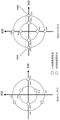
Fig. 20 shows the position of the reception quality deterioration point.
Fig. 21 shows the position of the reception quality deterioration point.
Fig. 22 shows an example of a frame configuration.
Fig. 23 shows an example of a frame configuration.
Fig. 24 shows an example of the mapping method.
Fig. 25 shows an example of the mapping method.
Fig. 26 shows an example of the structure of the weighted combination unit.
Fig. 27 shows an example of a symbol rearrangement method.
Fig. 28 shows an example of the configuration of a transmitting/receiving apparatus in the spatial multiplexing MIMO transmission system.
Fig. 29 shows an example of BER characteristics.
Fig. 30 shows an example of a spatial multiplexing type 2 × 2MIMO system model.
Fig. 31 shows the position of the reception deterioration point.
Fig. 32 shows the position of the reception deterioration point.
Fig. 33 shows the position of the reception deterioration point.
Fig. 34 shows the position of the reception deterioration point.
Fig. 35 shows the position of the reception deterioration point.
Fig. 36 shows a characteristic example of the minimum distance of the reception deterioration point in the complex number plane.
Fig. 37 shows a characteristic example of the minimum distance of the reception deterioration point in the complex number plane.
Fig. 38 shows the position of the reception deterioration point.
Fig. 39 shows the position of the reception deterioration point.
Fig. 40 shows an example of the configuration of a transmission device according to embodiment 7.
Fig. 41 shows an example of a frame configuration of a modulated signal transmitted by a transmission apparatus.
Fig. 42 shows the position of the reception deterioration point.
Fig. 43 shows the position of the reception deterioration point.
Fig. 44 shows the position of the reception deterioration point.
Fig. 45 shows the position of the reception deterioration point.
Fig. 46 shows the position of the reception deterioration point.
Fig. 47 shows an example of a frame structure in the time-frequency axis.
Fig. 48 shows an example of a frame structure on the time-frequency axis.
Fig. 49 shows a signal processing method.
Fig. 50 shows a structure of a modulated signal when space-time block coding is used.
Fig. 51 shows a detailed example of the frame structure in the time-frequency axis.
Fig. 52 shows an example of the configuration of the transmission device.
Fig. 53 shows an example of the configuration of the modulated signal generating units # 1 to # M in fig. 52.
Fig. 54 is a diagram showing a configuration of the OFDM-related processing unit (5207_1 and 5207_2) in fig. 52.
Fig. 55 shows a detailed example of the frame structure in the time-frequency axis.
Fig. 56 shows an example of the configuration of the receiving apparatus.
Fig. 57 is a diagram showing the configuration of the OFDM-scheme-related processing unit (5600_ X, 5600_ Y) in fig. 56.
Fig. 58 shows a detailed example of the frame structure in the time-frequency axis.
Fig. 59 shows an example of a broadcasting system.
Fig. 60 shows the position of the reception deterioration point.
Fig. 61 shows an example of the configuration of a transmitting apparatus when layered transmission is applied.
Fig. 62 shows an example of the configuration of a transmitting apparatus when layered transmission is applied.
Fig. 63 shows an example of precoding for an elementary stream.
Fig. 64 shows an example of precoding for an extended stream.
Fig. 65 shows an example of the arrangement of symbols of a modulated signal when layered transmission is applied.
Fig. 66 shows an example of the configuration of a signal processing section of a receiving apparatus when layered transmission is applied.
Fig. 67 shows an example of the configuration of a transmitting apparatus when hierarchical transmission is applied.
Fig. 68 shows an example of the configuration of a transmitting apparatus when hierarchical transmission is applied.
Fig. 69 shows an example of the structure of a symbol of a baseband signal.
Fig. 70 shows an example of the arrangement of symbols of a modulated signal when layered transmission is applied.
Fig. 71 shows an example of the configuration of a transmitting apparatus when hierarchical transmission is applied.
Fig. 72 shows an example of the configuration of a transmitting apparatus when layered transmission is applied.
Fig. 73 shows an example of the structure of a symbol of a baseband signal after space-time block coding.
Fig. 74 shows an example of the arrangement of symbols of a modulated signal when layered transmission is applied.
Fig. 75 shows an example of the arrangement of symbols of a modulated signal when layered transmission is applied.
Fig. 76 shows an example of changes in the number of symbols and the number of slots required for one encoded block when a block code is used.
Fig. 77 shows an example of changes in the number of symbols and the number of slots required for two coded blocks when a block code is used.
Fig. 78 is a diagram showing the overall configuration of a digital broadcasting system.
Fig. 79 is a block diagram showing an example of the structure of a receiver.
Fig. 80 is a diagram showing a structure of multiplexed data.
Fig. 81 is a diagram schematically showing how each stream is multiplexed in multiplexed data.
Fig. 82 is a diagram showing how a video stream is stored in a PES packet sequence.
Fig. 83 is a diagram showing the structure of a TS packet and a source packet in multiplexed data.
Fig. 84 is a diagram showing a data structure of the PMT.
Fig. 85 is a diagram showing an internal configuration of multiplexed data information.
Fig. 86 is a diagram showing an internal configuration of the stream attribute information.
Fig. 87 is a diagram showing a configuration of the video display/audio output device.
Fig. 88 is a diagram showing a configuration of a baseband signal replacement section.
Detailed Description
Embodiments of the present invention will be described in detail below with reference to the drawings.
(embodiment mode 1)
The transmission method, transmission device, reception method, and reception device of the present embodiment will be described in detail.
Before this description, an overview of a transmission method and a decoding method of a spatial multiplexing MIMO transmission system, which is a past system, will be described.
FIG. 1 shows Nt×NrStructure of a spatial multiplexing MIMO system. The information vector z is encoded and interleaved. Then, the vector u of the encoded bits is obtained as (u)1、…、uNt) As the output of the interleaving. Wherein u isi=(ui1、…、UiM) (M: the number of transmission bits per symbol). If the sending vector s is set as(s)1、…、sNt)TThen, the transmission signal from the transmission antenna # i is denoted as si=map(ui) Normalizing the transmit energy, which may be expressed as E { | si|2}=Es/Nt(Es: total energy per symbol). And, if the received vector is set as y ═ y1、…、yNr)TThen, it can be expressed as shown in the following formula (1).
[ numerical formula 1]

At this time, HNtNrDenotes a channel matrix, n ═ n1、…、nNr)TRepresenting a noise vector, niRepresents the mean value 0 and the variance σ2Complex gaussian noise of (1). Based on the relationship between the transmitted symbol and the received symbol introduced at the receiver, the probability of the received vector can be given in accordance with the multivariate gaussian distribution as in equation (2).
[ numerical formula 2]

Here, a receiver which performs iterative decoding as shown in fig. 1, which is configured by an external soft-in soft-out decoder and MIMO detection, will be described. The vector of log-likelihood ratios (L-value) in fig. 1 can be expressed as shown in formulas (3) to (5).
[ numerical formula 3]

[ numerical formula 4]

[ numerical formula 5]

< method of repetitive detection >
Here, for Nt×NrThe repetitive detection of MIMO signals in the spatial multiplexing MIMO system will be described.
X is defined as shown in formula (6)mnThe log likelihood ratio of (c).
[ numerical formula 6]

Equation (6) can be expressed as shown in equation (7) according to bayes' law.
[ number formula 7]

Wherein, set Umn,±1={u|u mn1| }, and, if In ∑ a is usedj~max In ajBy performing the approximation, equation (7) can be approximated as shown in equation (8). In addition, the symbols "to" represent approximations.
[ number formula 8]

P (u | u) in formula (8)mn) And InP (u | u)mn) Can be expressed as follows.
[ numerical formula 9]

[ numerical formula 10]

[ numerical formula 11]

Here, the logarithmic probability of the formula defined by formula (2) can be expressed as shown in formula (12).
[ numerical formula 12]

Therefore, according to the equations (7) and (13), the L-value after the last time in MAP or APP (a posteriori probability) can be expressed as follows.
[ numerical formula 13]

Hereinafter referred to as iterative APP decoding. In addition, according to expressions (8) and (12), in the Max-Log approximation based Log likelihood ratio (Max-LogAPP), the following L-value can be expressed as follows.
[ numerical formula 14]

[ numerical formula 15]

Hereinafter referred to as iterative Max-logAPP decoding. The extrinsic information required for the system that performs repeated decoding can be obtained by subtracting the prior input from equation (13) or (14).
< System model >
Here, as a 2 × 2 spatial multiplexing MIMO system, it is assumed that a stream A, B is provided with outer encoders respectively, and the two outer encoders are encoders of the same LDPC code (here, a description is given by taking as an example a configuration in which the outer encoder employs an LDPC code, but error correction coding used by the outer encoder is not limited to the LDPC code, and may be implemented using other error correction codes such as a turbo code, a convolutional code, and an LDPC convolutional code)a、πb). Here, let the modulation scheme be 2hQAM (h bits sent in one symbol).
It is assumed that the above-described iterative detection (iterative APP (or Max-logAPP) decoding) of the MIMO signal is performed in the receiver. It is assumed that sum-product decoding is performed as decoding of the LDPC code, for example.
Fig. 2 shows a frame structure, describing the order of symbols after interleaving. In this case, (i) is expressed by the following equationa,ja)、(ib,jb)。
[ number formula 16]

[ number formula 17]

At this time, ia、ibIndicating the order of the interleaved symbols, ja、jbIndicating a bit position (j) in a modulation schemea、jb=1、…、h),πa、πbRepresents the interleaver, omega, of stream A, Ba ia,ja、Ωb ib,jbIndicating the order of the data of stream A, B prior to interleaving. Wherein i is shown in FIG. 2a=ibThe frame structure of time.
< iterative decoding >
Here, the algorithm of sum-product decoding and iterative detection of MIMO signals used for decoding the LDPC code of the receiver will be described in detail.
sum-product decoding
Assume that the two-dimensional M × N matrix H ═ HmnThe check matrix of the LDPC code of the decoding object is. Define the set [1, N ] as shown in]Partial sets of {1,2, …, N }, a (m), b (N).
[ numerical formula 18]
A(m)≡{n:Hmn= 1} … type (18)
[ number formula 19]
B(n)≡{m:Hmn= 1} … type (19)
At this time, a (m) denotes a set of column indexes that is 1 in the mth row of the check matrix H, and b (n) denotes a set of row indexes that is 1 in the nth row of the check matrix H. The algorithm for sum-product decoding is as follows.
StepA · 1 (initialization): for satisfying HmnAll groups (m, n) of 1, a priori value-to-value ratio β is setmn0. Set the cycle variable (number of iterations) lsumSet the maximum number of cycles to 1sum,max。
Stepa.2 (line treatment): according to the sequence of M1, 2, … and M, aiming at satisfying HmnAll sets (m, n) of 1, the external value-to-value ratio α is updated using the update method described belowmn。
[ number formula 20]

[ numerical formula 21]

[ numerical formula 22]

Wherein f represents a function of Gallager. In addition, regarding λnThe solving method of (2) will be described in detail later.
StepA.3 (column treatment): according to the sequence of N being 1,2, … and N, aiming at satisfying HmnAll sets (m, n) of 1, the external value-to-value ratio β is updated using the update method described belowmn。
[ numerical formula 23]

StepA.4 (calculation of Log-likelihood ratio) for N ∈ [1, N]The log-likelihood ratio L is obtained as shown belown。
[ numerical formula 24]

StepA · 5 (count of number of repetitions): if l issum<lsum,maxThen 1 is madesumIncrement and return to stepa.2. In lsum=lsum,maxWhen the sum-product decoding is finished, the sum-product decoding is finished.
The above description relates to the operation of single sum-product decoding, and then, the MIMO signal is repeatedly detected, and the variables m, n, and α used in the above description of the operation of sum-product decodingmn、βmn、λn、LnIn ma、na、αa mana、βa mana、λna、LnaRepresenting variables in stream A, in mb、nb、αb mbnb、βb mbnb、λnb、LnbRepresenting the variables in stream B.
< repetitive detection of MIMO Signal >
Here, λ is used for repeated detection of MIMO signalsnThe solving method of (2) will be explained in detail.
From equation (1), the following equation holds.
[ number formula 25]

According to the frame structure shown in fig. 2, the following relational expression holds according to expressions (16) and (17).
[ number formula 26]

[ numerical formula 27]

At this time, na、nb∈[1,N]. Later, the MIMO signal is transmittedλ of number of times k of repeated detectionna、Lna、λnb、LnbAre respectively represented as lambdak,na、Lk,na、λk,nb、Lk,nb。
Step B · 1 (initial detection, k ═ 0): at the time of initial detection, λ is obtained as shown below0,na、λ0,nb。
Upon iterative APP decoding:
[ number formula 28]

Upon iterative Max-logAPP decoding:
[ numerical formula 29]

[ number formula 30]

Wherein X is a or b. Further, let the number of repetitions of the repeated detection of the MIMO signal be lmimoThe maximum number of repetitions is set to l when set to 0mimo,max。
Step B.2 (repeated detection; number of repetitions k): according to the expressions (11) (13) - (15) (16) (17), λ when repeating the number kk,na、λk,nbCan be expressed as shown in formulas (31) to (34). Wherein, (X, Y) ═ a, b) (b, a).
Upon iterative APP decoding:
[ number formula 31]

[ number formula 32]

Upon iterative Max-logAPP decoding:
[ numerical formula 33]

[ number formula 34]

Step B · 3 (counting of number of iterations, codeword estimation): if l ismimo<lmimo,maxThen 1 is mademimoIncremented, and returned to Step B · 2. In lmimo=lmimo,maxThen, the estimated code word is obtained as follows.
[ number formula 35]

Wherein X is a, b.
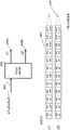
Fig. 3 shows an example of the configuration of a transmission device 300 according to the present embodiment. The encoding unit 302A receives the information (data) 301A and the frame configuration signal 313 as input, performs error correction encoding such as convolutional coding, LDPC coding, turbo coding, and the like in accordance with the frame configuration signal 313 (including information such as an error correction scheme, an encoding rate, and a block length used by the encoding unit 302A in error correction encoding of data, and the scheme specified by the frame configuration signal 313, and the error correction scheme may be switched), and outputs the encoded data 303A.
The mapping unit 306A receives the interleaved data 305A and the frame structure signal 313 as input, performs QPSK (Quadrature phase Shift Keying), 16QAM (16Quadrature Amplitude Modulation), 64QAM (64Quadrature Amplitude Modulation), and the like, and outputs a baseband signal 307A. (the modulation scheme may be switched according to the frame configuration signal 313).
Fig. 24 shows an example of a mapping method of an in-phase component I and a quadrature component Q constituting a baseband signal in QPSK modulation in an IQ plane. For example, as shown in fig. 24(a), when the input data is "00", the output I is 1.0 and Q is 1.0, which are the same from now on, and when the input data is "01", the output I is-1.0 and Q is 1.0, …, and so on. Fig. 24(B) shows an example of a mapping method in the IQ plane of QPSK modulation, which is different from fig. 24(a), and fig. 24(B) is different from fig. 24(a) in that the signal point in fig. 24(a) can be obtained by rotating around the origin. Such a star rotation method is disclosed in non-patent documents 9 and 10, and Cyclic Q Delay disclosed in non-patent documents 9 and 10 may be used. Fig. 25 shows a signal point arrangement in the IQ plane in 16QAM as an example different from fig. 24, and an example corresponding to fig. 24(a) is fig. 25(a), and an example corresponding to fig. 24(B) is fig. 25 (B).
The encoding unit 302B receives the information (data) 301B and the frame configuration signal 313 as input, performs error correction encoding such as convolutional code, LDPC code, turbo code, etc., in accordance with the frame configuration signal 313 (including information such as the error correction scheme, coding rate, and block length to be used, and the scheme specified by the frame configuration signal 313, and the error correction scheme may be switched), and outputs the encoded data 303B.
The mapping unit 306B receives the interleaved data 305B and the frame structure signal 313 as input, performs QPSK (Quadrature phase Shift Keying), 16QAM (16Quadrature Amplitude Modulation), 64QAM (64Quadrature Amplitude Modulation), and the like, and outputs a baseband signal 307B. (the modulation scheme may be switched according to the frame configuration signal 313.)
The weighted synthesis information generation unit 314 receives the frame structure signal 313 as an input, and outputs correlation information 315 based on the weighted synthesis method of the frame structure signal 313. In addition, the weighted synthesis method is characterized in that the weighted synthesis method is switched regularly.
The weighted synthesis unit 308A receives baseband signal 307A, baseband signal 307B, and information 315 relating to the weighted synthesis method as input, performs weighted synthesis of baseband signal 307A and baseband signal 307B based on information 315 relating to the weighted synthesis method, and outputs weighted-synthesized signal 309A. The details of the method of weighted synthesis will be described later.
The weighted synthesis unit 308B receives baseband signal 307A, baseband signal 307B, and information 315 relating to the weighted synthesis method as input, performs weighted synthesis of baseband signal 307A and baseband signal 307B based on information 315 relating to the weighted synthesis method, and outputs signal 309B after weighted synthesis.
Fig. 26 shows a structure of the weighted synthesis unit. The baseband signal 307A generates w11(t) s1(t) by multiplying w11(t), and generates w21(t) s1(t) by multiplying w21 (t). Similarly, the baseband signal 307B generates w12(t) s2(t) by multiplying w12(t), and generates w22(t) s2(t) by multiplying w22 (t). Then, z1(t) ═ w11(t) s1(t) + w12(t) s2(t), and z2(t) ═ w21(t) s1(t) + w22(t) s2(t) are obtained.
The details of the method of weighted synthesis will be described later.
Fig. 4 shows an example of the configuration of a transmission device 400 different from that of fig. 3. In fig. 4, a portion different from fig. 3 will be explained.
The encoding unit 402 receives the information (data) 401 and the frame configuration signal 313 as input, performs error correction encoding on the basis of the frame configuration signal 313, and outputs the encoded data 402.
The assigning unit 404 assigns the encoded data 403 as input, and outputs data 405A and data 405B. In addition, although fig. 4 describes a case where there is one encoding unit, the present invention can be similarly implemented when m (m is an integer equal to or greater than 1) encoding units are used, and the distribution unit divides encoded data generated by each encoding unit into two systems of data and outputs the data.
Fig. 5 shows an example of a frame structure on the time axis of the transmission device in the present embodiment. Symbol 500_1 is a symbol for notifying a transmission method to a receiving apparatus, and is used for transmitting, for example, information of an error correction method used for transmitting a data symbol, an encoding rate thereof, information of a modulation method used for transmitting a data symbol, and the like.
Symbol 501_1 is a symbol for estimating channel fluctuation of modulated signal z1(t) { where t represents time } transmitted by the transmission apparatus. Symbol 502_1 is a data symbol transmitted by modulation signal z1(t) at symbol number u (on the time axis), and symbol 503_1 is a data symbol transmitted by modulation signal z1(t) at symbol number u + 1.
Symbol 501_2 is a symbol for estimating channel fluctuation of modulated signal z2(t) { where t represents time } transmitted by the transmission apparatus. Symbol 502_2 is a data symbol transmitted with symbol number u for modulated signal z2(t), and symbol 503_2 is a data symbol transmitted with symbol number u +1 for modulated signal z2 (t).
The relationship between the modulated signal z1(t) and the modulated signal z2(t) transmitted from the transmitter and the received signals r1(t) and r2(t) transmitted from the transmitter will be described.
In fig. 5, 504#1 and 504#2 denote transmission antennas of a transmission device, 505#1 and 505#2 denote reception antennas of a reception device, and the transmission device transmits a modulated signal z1(t) from transmission antenna 504#1 and transmits a modulated signal z2(t) from transmission antenna 504# 2. At this time, it is assumed that the modulated signal z1(t) and the modulated signal z2(t) occupy the same (common) frequency (frequency band). Transmitting antenna of transmitting device and receiving deviceIs h, the channel fluctuation of each receiving antenna is set to11(t)、h12(t)、h21(t)、h22(t), the following relational expression holds when the received signal received by the receiving antenna 505#1 of the receiving apparatus is r1(t) and the received signal received by the receiving antenna 505#2 of the receiving apparatus is r2 (t).
[ number formula 36]

Fig. 6 is a diagram related to a weighting method (Precoding) method) according to the present embodiment, and the weighting and combining unit 600 is a weighting and combining unit that integrates both the weighting and combining units 308A and 308B in fig. 3. As shown in fig. 6, streams s1(t) and s2(t) correspond to baseband signals 307A and 307B in fig. 3, that is, in-phase I and quadrature Q components of the baseband signals mapped according to the modulation schemes such as QPSK, 16QAM, and 64 QAM. As shown in the frame configuration of fig. 6, in the stream s1(t), the signal of the symbol number u is represented as s1(u), and the signal of the symbol number u +1 is represented as s1(u +1) and …. Similarly, in the stream s2(t), the signal of the symbol number u is represented as s2(u), and the signal of the symbol number u +1 is represented as s2(u +1) and …. Then, the weighting synthesis unit 600 receives the baseband signals 307A (s1(t)) and 307B (s2(t)) in fig. 3 and the information 315 related to the weighting information as input, performs a weighting method based on the information 315 related to the weighting information, and outputs the weighted and synthesized signals 309A (z1(t)) and 309B (z2(t)) shown in fig. 3. In this case, z1(t) and z2(t) can be represented as follows.
In the case of symbol number 4i (i is an integer of 0 or more):
[ numerical formula 37]

Where j represents an imaginary unit.
At symbol number 4i + 1:
[ number formula 38]

At symbol number 4i + 2:
[ number formula 39]

At symbol number 4i + 3:
[ number formula 40]

Thus, the weight combining unit shown in fig. 6 regularly switches the precoding weights in 4-slot cycles. (however, here, the precoding weights are switched regularly in 4 slots, but the number of regularly switched slots is not limited to 4 slots.)
It is possible to greatly improve reception quality if a special precoding matrix is used in an LOS environment, the special precoding matrix being different depending on the condition of a direct wave. However, there is a certain rule in the LOS environment, and if a special precoding matrix is regularly switched according to the rule, the reception quality of data is greatly improved. On the other hand, when the precoding matrix is switched at random, there is a possibility that only a precoding matrix that is not suitable for the imbalance (biased) of the LOS environment is precoded in addition to the possibility of a precoding matrix other than the special precoding matrix described above, and therefore good reception quality is not necessarily obtained in the LOS environment. Therefore, a precoding switching method suitable for an LOS environment needs to be realized, and the invention provides a precoding method related to the method.
Fig. 7 shows an example of the configuration of a receiving apparatus 700 according to the present embodiment. The radio unit 703_ X receives a received signal 702_ X received via the antenna 701_ X as an input, performs processing such as frequency conversion and quadrature demodulation, and outputs a baseband signal 704_ X.
The channel fluctuation estimating section 705_1 in the modulated signal z1 transmitted by the transmitter receives the baseband signal 704_ X as input, extracts the reference symbol 501_1 for channel estimation in fig. 5, estimates a value corresponding to h11 of equation (36), and outputs a channel estimation signal 706_ 1.
The channel fluctuation estimating section 705_2 in the modulated signal z2 transmitted by the transmitter receives the baseband signal 704_ X as input, extracts the reference symbol 501_2 for channel estimation in fig. 5, estimates a value corresponding to h12 of equation (36), and outputs a channel estimation signal 706_ 2.
The radio unit 703_ Y receives a received signal 702_ Y received via the antenna 701_ Y as an input, performs processing such as frequency conversion and quadrature demodulation, and outputs a baseband signal 704_ Y.
The channel fluctuation estimating section 707_1 in the modulated signal z1 transmitted by the transmitting apparatus receives the baseband signal 704_ Y as input, extracts the reference symbol 501_1 for channel estimation in fig. 5, estimates a value corresponding to h21 of equation (36), and outputs a channel estimation signal 708_ 1.
The channel fluctuation estimating section 707_2 in the modulated signal z2 transmitted by the transmitting apparatus receives the baseband signal 704_ Y as input, extracts the reference symbol 501_2 for channel estimation in fig. 5, estimates a value corresponding to h22 of equation (36), and outputs a channel estimation signal 708_ 2.
The control information decoding section 709 receives baseband signals 704_ X and 704_ Y as inputs, detects a symbol 500_1 for notifying the transmission method shown in fig. 5, and outputs a signal 710 related to information of the transmission method notified by the transmission apparatus.
The signal processing section 711 receives the baseband signals 704_ X and 704_ Y, the channel estimation signals 706_1, 706_2, 708_1, and 708_2, and the signal 710 related to the information of the transmission method notified by the transmission apparatus as input, performs detection and decoding, and outputs the received data 712_1 and 712_ 2.
Next, the operation of the signal processing unit 711 in fig. 7 will be described in detail. Fig. 8 shows an example of the configuration of the signal processing unit 711 according to the present embodiment. Fig. 8 is mainly composed of an INNER MIMO detector, a soft-in/soft-out decoder, and a weight coefficient generator. Although the method of repeating decoding with such a configuration is described in detail in non-patent documents 2 and 3, the MIMO transmission method described in non-patent documents 2 and 3 is a spatial multiplexing MIMO transmission method, and the transmission method of the present embodiment is a MIMO transmission method in which the time and the precoding weight are changed, which is different from non-patent documents 2 and 3. Let h (t) be the (channel) matrix in equation (36), w (t) be the precoding weight matrix in fig. 6 (where the precoding weight matrix varies depending on t), and r (t) be the reception vector (r1(t), r2(t))TLet the flow vector be S (t) ═ (s1(t), s2(t))TAt this time, the following relational expression is established.
[ number formula 41]
R (t) ═ h (t) w (t) s (t) … formula (41)
In this case, the receiving apparatus can apply the decoding methods of non-patent documents 2 and 3 to the received vector r (t) by regarding h (t) w (t) as a channel matrix.
Therefore, the weighting factor generation unit 819 in fig. 8 receives a signal 818 (corresponding to 710 in fig. 7) relating to information on a transmission method notified by the transmission apparatus as an input, and outputs a signal 820 relating to information on a weighting factor.
The inner MIMO detector 803 receives a signal 820 related to the information of the weighting coefficients as an input, and performs the calculation of the formula (41) using the signal. Then, the detection/decoding is repeated to explain the operation.
In the signal processing unit of fig. 8, the processing method shown in fig. 10 needs to be executed in order to perform iterative decoding (iterative detection). First, 1 codeword (or 1 frame) of modulated signal (stream) s1 and 1 codeword (or 1 frame) of modulated signal (stream) s2 are decoded. As a result, the Log-LikelihoodRatio (LLR) of each bit of the 1 codeword (or 1 frame) of modulated signal (stream) s1 and the 1 codeword (or 1 frame) of modulated signal (stream) s2 can be obtained from the soft-in soft-out decoder. Then, the LLR is used to perform detection/decoding again. This operation is repeated a plurality of times (this operation is referred to as repeated decoding (repeated detection)). Hereinafter, a method of generating a Log Likelihood Ratio (LLR) of a symbol at a specific time in 1 frame will be mainly described.
In fig. 8, the storage unit 815 receives as input a baseband signal 801X (corresponding to the baseband signal 704_ X in fig. 7), a channel estimation signal group 802X (corresponding to the channel estimation signals 706_1 and 706_2 in fig. 7), a baseband signal 801Y (corresponding to the baseband signal 704_ Y in fig. 7), and a channel estimation signal group 802Y (corresponding to the channel estimation signals 708_1 and 708_2 in fig. 7), executes (calculates) h (t) w (t) in expression (41) so as to perform iterative decoding (iterative detection), and stores the calculated matrix as a modified channel signal group. The storage unit 815 outputs the signals as a baseband signal 816X, a modified channel estimation signal group 817X, a baseband signal 816Y, and a modified channel estimation signal group 817Y, if necessary.
The following operations will be described in terms of the case of initial detection and the case of repeated decoding (repeated detection).
< initial detection case >
The INNER MIMO detector 803 receives as input a baseband signal 801X, a channel estimation signal group 802X, a baseband signal 801Y, and a channel estimation signal group 802Y. Here, the modulation scheme of the modulated signal (stream) s1 and the modulated signal (stream) s2 is 16 QAM.
The INNER MIMO detector 803 first performs h (t) w (t) on the channel estimation signal group 802X and the channel estimation signal group 802Y to obtain a candidate signal point corresponding to the baseband signal 801X. The state at this time is shown in fig. 11. In fig. 11, ● (black dots) indicates candidate signal points in the IQ plane, and since the modulation scheme is 16QAM, there are 256 candidate signal points. (the conceptual diagram is shown in fig. 11, and 256 candidate signal points are not shown.) here, 4 bits transmitted in the modulation signal s1 are set as b0, b1, b2, and b3, and are shown inThe 4 bits transmitted in the modulation signal s2 are set to b4, b5, b6, and b7, and candidate signal points corresponding to (b0, b1, b2, b3, b4, b5, b6, and b7) exist in fig. 11. Then, the squared euclidian distance between the received signal point 1101 (corresponding to the baseband signal 801X) and each candidate signal point is obtained. Then, each squared euclidean distance is divided by the variance σ of the noise2. Therefore, a value obtained by dividing the squared euclidian distance between the candidate signal point and the received signal point corresponding to (b0, b1, b2, b3, b4, b5, b6, b7) by the variance of the noise is obtained as Ex (b0, b1, b2, b3, b4, b5, b6, b 7).
Similarly, h (t) w (t) is executed from the channel estimation signal group 802X and the channel estimation signal group 802Y to determine candidate signal points corresponding to the baseband signal 801Y, determine the squared euclidian distance to the received signal point (corresponding to the baseband signal 801Y), and divide the squared euclidian distance by the variance σ of noise2. Therefore, the squared euclidian distance between the candidate signal point corresponding to (b0, b1, b2, b3, b4, b5, b6, b7) and the received signal point is divided by the variance of the noise to obtain Ey (b0, b1, b2, b3, b4, b5, b6, b 7).
Then, Ex (b0, b1, b2, b3, b4, b5, b6, b7) + Ey (b0, b1, b2, b3, b4, b5, b6, b7) ═ E (b0, b1, b2, b3, b4, b5, b6, b7) is obtained.
The inerr MIMO detector 803 outputs E (b0, b1, b2, b3, b4, b5, b6, b7) as the signal 804.
The log-likelihood calculator 805A receives the signal 804 as input, calculates log-likelihood (log likelihood) of the bits b0 and b1 and b2 and b3, and outputs a log-likelihood signal 806A. In the calculation of the log likelihood, the log likelihood of "1" and the log likelihood of "0" are calculated. The calculation methods are shown in equations (28), (29) and (30), and are described in detail in non-patent documents 2 and 3.
Similarly, the log-likelihood calculator 805B receives the signal 804 as input, calculates the log-likelihood of the bits B4 and B5 and B6 and B7, and outputs a log-likelihood signal 806B.
Deinterleaver (807A) receives log-likelihood signal 806A as input, performs deinterleaving corresponding to the interleaver (304A) in fig. 3), and outputs deinterleaved log-likelihood signal 808A.
Similarly, a deinterleaver (807B) receives log-likelihood signal 806B as an input, performs deinterleaving corresponding to the interleaver (304B) in fig. 3), and outputs deinterleaved log-likelihood signal 808B.
Log-likelihood Ratio calculator 809A receives log-likelihood signal 808A after deinterleaving as an input, calculates a log-likelihood Ratio (LLR: log-likelihood Ratio) of bits encoded by encoder 302A in fig. 3, and outputs log-likelihood Ratio signal 810A.
Similarly, log-likelihood Ratio calculator 809B receives log-likelihood signal 808B after deinterleaving as an input, calculates a log-likelihood Ratio (LLR: log-likelihood Ratio) of bits encoded by encoder 302B in fig. 3, and outputs log-likelihood Ratio signal 810B.
Soft-in and soft-out decoder 811A decodes log-likelihood ratio signal 810A as an input and outputs decoded log-likelihood ratio 812A.
Similarly, soft-in soft-out decoder 811B decodes log-likelihood ratio signal 810B as an input, and outputs decoded log-likelihood ratio 812B.
< case of repeated decoding (repeated detection), number of repetitions k >
Interleaver (813A) interleaves the decoded log-likelihood ratios 812A obtained by the k-1 st soft-in and soft-out decoding as input, and outputs interleaved log-likelihood ratios 814A. At this time, the pattern of interleaving by the interleaver (813A) is the same as that of the interleaver (304A) in fig. 3.
Interleaver (813B) interleaves the decoded log-likelihood ratios 812B obtained by the k-1 st soft-in and soft-out decoding as input, and outputs interleaved log-likelihood ratios 814B. At this time, the pattern of interleaving by the interleaver (813B) is the same as that of the interleaver (304B) in fig. 3.
INNER MIMO detection section 803 receives baseband signal 816X, modified channel estimation signal group 817X, baseband signal 816Y, modified channel estimation signal group 817Y, interleaved log-likelihood ratio 814A, and interleaved log-likelihood ratio 814B as input. Here, the delay time is generated by repeated decoding, because the baseband signal 801X, the channel estimation signal group 802X, the baseband signal 801Y, and the channel estimation signal group 802Y are not used, but the baseband signal 816X, the modified channel estimation signal group 817X, the baseband signal 816Y, and the modified channel estimation signal group 817Y are used.
The operation of the INNER MIMO detection unit 803 at the time of repeated decoding differs from the operation at the time of initial detection in that the interleaved log-likelihood ratio 814A and the interleaved log-likelihood ratio 814B are used at the time of signal processing. The inermimo detector 803 first obtains E (b0, b1, b2, b3, b4, b5, b6, b7) in the same manner as in the initial detection. Then, coefficients corresponding to expressions (11) and (32) are obtained from the interleaved log-likelihood ratio 814A and the interleaved log-likelihood ratio 914B. Then, the value of E (b0, b1, b2, b3, b4, b5, b6, b7) is corrected using the obtained coefficient, and the corrected value is set as E' (b0, b1, b2, b3, b4, b5, b6, b7) and output as the signal 804.
The log-likelihood calculator 805A receives the signal 804 as input, calculates log-likelihood (log likelihood) of the bits b0 and b1 and b2 and b3, and outputs a log-likelihood signal 806A. In the calculation of the log likelihood, the log likelihood of "1" and the log likelihood of "0" are calculated. The calculation methods are described in non-patent documents 2 and 3, as shown in equations (31), (32), (33), (34) and (35).
Similarly, the log-likelihood calculator 805B receives the signal 804 as input, calculates the log-likelihood of the bits B4 and B5 and B6 and B7, and outputs a log-likelihood signal 806B. The operation after deinterleaving is the same as that of the initial detection.
Although fig. 8 shows the configuration of the signal processing section when performing repeated detection, the repeated detection is not necessarily required to obtain good reception quality, and may be a configuration without interleavers 813A and 813B, which are components required for only repeated detection. At this time, the INNER MIMO detection unit 803 does not perform repeated detection.
The important part of the present embodiment is to perform the calculation of h (t) w (t). As described in non-patent document 5 and the like, initial detection and repeated detection may be performed using QR decomposition.
As described in non-patent document 11, initial detection may be performed by performing linear operations of MMSE (minimum mean Square Error) and ZF (Zero Forcing) based on h (t) w (t).
Fig. 9 shows a configuration of a signal processing unit different from that of fig. 8, and is a signal processing unit for a modulated signal transmitted by the transmission device shown in fig. 4. The difference from fig. 8 is the number of soft-in soft-out decodings, and a soft-in soft-out decoder 901 decodes the input of log-likelihood ratio signals 810A and 810B, and outputs a decoded log-likelihood ratio 902. The allocating unit 903 allocates the decoded log-likelihood ratios 902 as input. The other portions are the same operations as those in fig. 8.
Fig. 12 shows BER characteristics when the transmission scheme is the transmission method using precoding weights according to the present embodiment under the same conditions as those shown in fig. 29. Fig. 12 (a) shows BER characteristics of Max-log-APP (see non-patent documents 1 and 2) (APP: aposterioripability) in which repetitive detection is not performed, and fig. 12 (B) shows BER characteristics of Max-log-APP (see non-patent documents 1 and 2) (in which the number of repetitions is 5) in which repetitive detection is performed. As can be seen by comparing fig. 12 and fig. 29, when the transmission method of the present embodiment is used, the BER characteristic when the rice factor is large is significantly improved as compared with the BER characteristic when spatial multiplexing MIMO transmission is used, and the effectiveness of the method of the present embodiment can be confirmed.
As described above, when the transmitting apparatus of the MIMO transmission system transmits a plurality of modulated signals from a plurality of antennas as in the present embodiment, by switching the precoding weights over time and switching regularly, the effect of improving the transmission quality can be obtained in the LOS environment where direct waves dominate as compared with the case of employing spatial multiplexing MIMO transmission in the past.
In the present embodiment, the operation has been described while limiting the number of antennas particularly with respect to the configuration of the receiving apparatus, but the operation can be similarly performed even when the number of antennas is increased. That is, the number of antennas of the receiving apparatus does not affect the operation and effect of the present embodiment. In the present embodiment, the LDPC code is particularly taken as an example, but the present invention is not limited thereto, and the decoding method is not limited to the sum-product decoding (sum-product decoding) and other soft-in and soft-out decoding methods such as BCJR algorithm, SOVA algorithm, and Msx-log-MAP algorithm may be used. Details of the method are described in non-patent document 6.
In the present embodiment, a single-carrier method is described as an example, but the present invention is not limited to this, and can be similarly implemented when multicarrier transmission is performed. Therefore, the present invention can be similarly applied to, for example, a spread spectrum communication system, an OFDM (Orthogonal Frequency Division Multiplexing) system, an SC-FDMA (Single carrier Frequency Division Multiple Access) system, an SC-OFDM (Single carrier Orthogonal Frequency Division Multiplexing) system, a wavelet (wavelet) OFDM system disclosed in non-patent document 7, and the like. In the present embodiment, symbols other than data symbols, for example, pilot symbols (preamble, unique word, etc.), symbols for transmission of control information, and the like may be arbitrarily arranged in a frame.
Next, an example of the case of adopting the OFDM scheme will be described as an example of the multicarrier scheme.
Fig. 13 shows a configuration of a transmitting apparatus in the case of adopting the OFDM scheme. In fig. 13, the same reference numerals are given to the parts that perform the same operations as those in fig. 3.
The OFDM-related processing unit 1301A receives the weighted signal 309A as an input, performs OFDM-related processing, and outputs a transmission signal 1302A. Similarly, the OFDM-related processing unit 1301B receives the weighted signal 309B as input, and outputs a transmission signal 1302B.
Fig. 14 shows an example of the configuration of the OFDM-related processing units 1301A and 1301B in fig. 13, and the portions related to 1301A to 312A in fig. 13 are 1401A to 1410A, and the portions related to 1301B to 312B are 1401B to 1410B.
The serial-parallel conversion unit 1402A performs serial-parallel conversion of the weighted signal 1401A (corresponding to the weighted signal 309A in fig. 13), and outputs a parallel signal 1403A.
The rearrangement unit 1404A rearranges the parallel signal 1403A as an input, and outputs a rearranged signal 1405A. The rearrangement will be described in detail later.
The inverse fast fourier transform unit 1406A receives the rearranged signal 1405A as an input, performs inverse fast fourier transform, and outputs an inverse fast fourier transformed signal 1407A.
The radio unit 1408A receives the signal 1407A after the inverse fast fourier transform as an input, performs processing such as frequency conversion and amplification, and outputs a modulated signal 1409A, and the modulated signal 1409A is output from the antenna 1410A as a radio wave.
The serial-parallel conversion unit 1402B performs serial-parallel conversion of the weighted signal 1401B (corresponding to the weighted signal 309B in fig. 13), and outputs a parallel signal 1403B.
The rearrangement unit 1404B rearranges the parallel signal 1403B as an input, and outputs a rearranged signal 1405B. The rearrangement will be described in detail later.
The inverse fast fourier transform unit 1406B receives the rearranged signal 1405B as an input, performs inverse fast fourier transform, and outputs an inverse fast fourier transformed signal 1407B.
The radio unit 1408B receives the signal 1407B after the ifft as an input, performs processing such as frequency conversion and amplification, and outputs a modulated signal 1409B, and the modulated signal 1409B is output from the antenna 1410B as a radio wave.
In the transmitting apparatus of fig. 3, since a multicarrier transmission scheme is not used, precoding is switched in 4 cycles as shown in fig. 6, and symbols after precoding are arranged in the time axis direction. When a multicarrier transmission scheme such as the OFDM scheme shown in fig. 13 is used, it is needless to say that a scheme in which precoded symbols are arranged in the time axis direction as shown in fig. 3 and the arrangement is performed for each (sub) carrier is conceivable, but a scheme in which the precoding is arranged in the frequency axis direction or both the frequency axis and the time axis are used is also conceivable for the multicarrier transmission scheme. This point will be explained later.
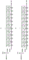
Fig. 15 shows an example of a method of rearranging symbols by rearrangement units 1401A and 1401B shown in fig. 14, in which the horizontal axis shows frequency and the vertical axis shows time, the frequency axis is formed by (sub) carriers 0 to 9, modulated signals z1 and z2 use the same frequency band at the same time (time), fig. 15(a) shows a method of rearranging symbols of modulated signal z1, and fig. 15(B) shows a method of rearranging symbols of modulated signal z 2. Serial-parallel conversion section 1402A sequentially assigns numbers # 1, #2, #3, #4, and … to the symbols of signal 1401A to which weighting is applied as input. At this time, as shown in fig. 15(a), symbols # 1, #2, #3, #4, and … are arranged in order from carrier 0, symbols # 1 to #9 are arranged at time $1, and symbols # 10 to #19 are arranged at time $2, and the arrangement is performed regularly.
Similarly, serial-parallel conversion section 1402B sequentially assigns numbers # 1, #2, #3, #4, and … to the symbols of signal 1401B as input after being weighted. At this time, as shown in fig. 15(b), symbols # 1, #2, #3, #4, and … are arranged in order from carrier 0, symbols # 1 to #9 are arranged at time $1, and symbols # 10 to #19 are arranged at time $2, and the arrangement is performed regularly.
Further, a symbol group 1501 and a symbol group 1502 shown in fig. 15 are symbols of 1 cycle when the precoding weight switching method shown in fig. 6 is used, a symbol # 0 is a symbol when the precoding weight of the slot 4i shown in fig. 6 is used, a symbol # 1 is a symbol when the precoding weight of the slot 4i +1 shown in fig. 6 is used, a symbol # 2 is a symbol when the precoding weight of the slot 4i +2 shown in fig. 6 is used, and a symbol # 3 is a symbol when the precoding weight of the slot 4i +3 shown in fig. 6 is used. Therefore, in the symbol # x, when x mod4 is 0, the symbol # x is a symbol when the precoding weight of the slot 4i shown in fig. 6 is used, when x mod4 is 1, the symbol # x is a symbol when the precoding weight of the slot 4i +1 shown in fig. 6 is used, when x mod4 is 2, the symbol # x is a symbol when the precoding weight of the slot 4i +2 shown in fig. 6 is used, and when x mod4 is 3, the symbol # x is a symbol when the precoding weight of the slot 4i +3 shown in fig. 6 is used.
In this way, when a multicarrier transmission scheme such as the OFDM scheme is employed, the symbols can be arranged in the frequency axis direction, which is different from the single carrier transmission scheme. The arrangement of the symbols is not limited to the arrangement shown in fig. 15. Other examples will be described with reference to fig. 16 and 17.
Fig. 16 shows an example of a method of rearranging symbols by rearrangement units 1401A and 1401B shown in fig. 14, which is different from fig. 15, in which the horizontal axis represents frequency and the vertical axis represents time, fig. 16(a) shows a method of rearranging symbols of modulated signal z1, and fig. 16(B) shows a method of rearranging symbols of modulated signal z 2. Fig. 16(a) and (B) are different from fig. 15 in that the method of rearranging symbols of modulated signal z1 is different from the method of rearranging symbols of modulated signal z2, and in fig. 16(B), symbols # 0 to #5 are arranged in carriers 4 to 9, symbols # 6 to #9 are arranged in carriers 0 to 3, and thereafter, symbols #10 to #19 are arranged in the same order in each carrier. In this case, as in fig. 15, symbol group 1601 and symbol group 1602 shown in fig. 16 are symbols of 1 cycle in the case where the precoding weight switching method shown in fig. 6 is used.
Fig. 17 shows an example of a method of rearranging symbols by rearrangement units 1401A and 1401B shown in fig. 14, which is different from fig. 15 and in which the horizontal axis represents frequency and the vertical axis represents time, fig. 17(a) shows a method of rearranging symbols of modulated signal z1, and fig. 17(B) shows a method of rearranging symbols of modulated signal z 2. Fig. 17(a) (B) is different from fig. 15 in that symbols are sequentially arranged in carriers in fig. 15, and symbols are not sequentially arranged in carriers in fig. 17. Of course, in fig. 17, the rearrangement method of the symbols of modulated signal z1 and the rearrangement method of modulated signal z2 may be different from each other as in fig. 16.
Fig. 18 shows an example of a method of rearranging symbols by rearrangement units 1401A and 1401B shown in fig. 14, which is different from fig. 15 to 17 and in which the horizontal axis represents frequency and the vertical axis represents time, fig. 18(a) shows a method of rearranging symbols of modulated signal z1, and fig. 18(B) shows a method of rearranging symbols of modulated signal z 2. In fig. 15 to 17, symbols are arranged in the frequency axis direction, and in fig. 18, symbols are arranged using both the frequency axis and the time axis.
In fig. 6, an example of switching by 4 slots is described with respect to switching of precoding weights, and an example of switching by 8 slots is described here. Symbol group 1801, symbol group 1802 shown in fig. 18 are symbols of 1 cycle (therefore, 8 symbols) when the precoding weight switching method is used, symbol # 0 is a symbol when the precoding weight of slot 8i is used, symbol # 1 is a symbol when the precoding weight of slot 8i +1 is used, symbol # 2 is a symbol when the precoding weight of slot 8i +2 is used, symbol # 3 is a symbol when the precoding weight of slot 8i +3 is used, symbol # 4 is a symbol when the precoding weight of slot 8i +4 is used, symbol # 5 is a symbol when the precoding weight of slot 8i +5 is used, symbol # 6 is a symbol when the precoding weight of slot 8i +6 is used, and symbol # 7 is a symbol when the precoding weight of slot 8i +7 is used. Therefore, in the symbol # x, when x mod 8 is 0, the symbol # x is a symbol when the precoding weight of the slot 8i is used, when x mod 8 is 1, the symbol # x is a symbol when the precoding weight of the slot 8i +1 is used, when x mod 8 is 2, the symbol # x is a symbol when the precoding weight of the slot 8i +2 is used, when x mod 8 is 3, the symbol # x is a symbol when the precoding weight of the slot 8i +3 is used, when x mod 8 is 4, the symbol # x is a symbol when the precoding weight of the slot 8i +4 is used, when x mod 8 is 5, the symbol # x is a symbol when the precoding weight of the slot 8i +5 is used, when x mod 8 is 6, the symbol # x is a symbol when the precoding weight of the slot 8i +6 is used, when x mod 8 is 7, symbol # x is a symbol when the precoding weight of slot 8i +7 is used. In the arrangement of symbols shown in fig. 18, symbols of 1 cycle are arranged using 8 slots, which are 4 slots in the time axis direction and 2 slots in the frequency axis direction, but in this case, if the number of symbols of 1 cycle is m × n symbols (that is, precoding weights are m × n types), the number of slots (the number of carriers) in the frequency axis direction used for arranging symbols of 1 cycle is n, and the number of slots used in the time axis direction is m, m > n can be used. Thus, the phase of the direct wave is more gentle in the time axis than in the frequency axis. Therefore, when the precoding weight is changed in the present embodiment in order to reduce the influence of a constant direct wave, it is desirable to reduce the variation of the direct wave in the period in which the change of the precoding weight is performed. Therefore, m > n can be set. In addition, by considering the above factors, if rearrangement is performed using both the frequency axis and the time axis as shown in fig. 18, the possibility that the direct wave becomes constant increases, as compared with the case where symbols are rearranged only in the frequency axis direction or only in the time axis direction, and the effect of the present invention can be easily obtained. However, when the signals are arranged in the frequency axis direction, the diversity gain (diversity gain) may be obtained because the frequency axis fluctuates relatively rapidly, and therefore, the rearrangement method using both the frequency axis and the time axis is not necessarily the optimal method.
Fig. 19 shows an example of a method of rearranging symbols by rearrangement units 1401A and 1401B shown in fig. 14, which is different from fig. 18 and in which the horizontal axis represents frequency and the vertical axis represents time, fig. 19(a) shows a method of rearranging symbols of modulated signal z1, and fig. 19(B) shows a method of rearranging symbols of modulated signal z 2. Fig. 19 is similar to fig. 18 in that symbols are arranged in both the frequency and time axes, but differs from fig. 18 in that the symbols are arranged in the time axis direction after giving priority to the frequency direction in fig. 18, and in that the symbols are arranged in the time axis direction after giving priority to the time axis direction in fig. 19. In fig. 19, symbol groups 1901 and 1902 are symbols of 1 cycle when the precoding switching method is used.
In fig. 18 and 19, similarly to fig. 16, even if the symbols of modulated signal z1 are arranged in a manner different from the symbols of modulated signal z2, the same effect can be achieved and high reception quality can be obtained. In fig. 18 and 19, even if symbols are arranged in the order shown in fig. 17, the same effect can be obtained, and a high reception quality can be obtained.
Fig. 27 shows an example of a method of rearranging symbols by the rearrangement units 1401A and 1401B shown in fig. 14, which is different from the above-described method and in which the horizontal axis represents frequency and the vertical axis represents time, and describes a case where the precoding matrix is switched regularly using 4 slots as shown in equations (37) to (40). It is characterized in that the symbols are sequentially arranged in the frequency axis direction in fig. 27, but a cyclic shift of n (n is 1 in the example of fig. 27) symbols is performed in a cycle while advancing in the time axis direction. The precoding matrices of equations (37) to (40) are switched among the 4 symbols shown in symbol group 2710 in the frequency axis direction in fig. 27.
In this case, it is assumed that precoding using the precoding matrix of expression (37) is performed in the #0 symbol, precoding using the precoding matrix of expression (38) is performed in the #1 symbol, precoding using the precoding matrix of expression (39) is performed in the #2 symbol, and precoding using the precoding matrix of expression (40) is performed in the #3 symbol.
Similarly, for the symbol group 2720 in the frequency axis direction, it is assumed that precoding using the precoding matrix of expression (37) is performed for a #4 symbol, precoding using the precoding matrix of expression (38) is performed for a #5 symbol, precoding using the precoding matrix of expression (39) is performed for a #6 symbol, and precoding using the precoding matrix of expression (40) is performed for a #7 symbol.
The switching of the precoding matrix described above is performed in the symbol at time $1, and since the cyclic shift is performed in the time axis direction, the switching of the precoding matrix is performed as follows for the symbol groups 2701, 2702, 2703, and 2704.
In the symbol group 2701 in the time axis direction, it is assumed that precoding using the precoding matrix of expression (37) is performed in symbol # 0, precoding using the precoding matrix of expression (38) is performed in symbol # 9, precoding using the precoding matrix of expression (39) is performed in symbol # 18, and precoding using the precoding matrix of expression (40) is performed in symbol # 27.
In the symbol group 2702 in the time axis direction, it is assumed that precoding using the precoding matrix of expression (37) is performed in symbol # 28, precoding using the precoding matrix of expression (38) is performed in symbol # 1, precoding using the precoding matrix of expression (39) is performed in symbol # 10, and precoding using the precoding matrix of expression (40) is performed in symbol # 19.
In the symbol group 2703 in the time axis direction, it is assumed that precoding using the precoding matrix of expression (37) is performed in symbol # 20, precoding using the precoding matrix of expression (38) is performed in symbol # 29, precoding using the precoding matrix of expression (39) is performed in symbol # 1, and precoding using the precoding matrix of expression (40) is performed in symbol # 10.
In the symbol group 2704 in the time axis direction, it is assumed that precoding using the precoding matrix of expression (37) is performed in symbol # 12, precoding using the precoding matrix of expression (38) is performed in symbol # 21, precoding using the precoding matrix of expression (39) is performed in symbol # 30, and precoding using the precoding matrix of expression (40) is performed in symbol # 3.
With regard to the feature of fig. 27, when focusing on, for example, the #11 symbol, the symbols (#10 and #12) on both sides in the frequency axis direction at the same time are precoded using a precoding matrix different from #11, and the symbols (#2 and #20) on both sides in the time axis direction of the same carrier of the #11 symbol are precoded using a precoding matrix different from # 11. Also, this is not limited to the #11 symbol, and all symbols of symbols existing on both sides in the frequency axis direction and the time axis direction have the same characteristics as the #11 symbol. Therefore, by effectively switching the precoding matrix, it will not be easily affected by the constant condition for the direct wave, and thus the possibility of the reception quality of data being improved increases.
In fig. 27, the explanation is given assuming that n is 1, but the invention is not limited to this, and the same can be applied to the case where n is 3. In fig. 27, when symbols are arranged along the frequency axis and time advances in the axial direction, the above-described feature is realized by cyclically shifting the order of arrangement of the symbols and providing such a feature, but there is also a method of realizing the above-described feature by randomly (or regularly) arranging the symbols.
(embodiment mode 2)
While embodiment 1 describes a case where precoding weights are regularly switched as shown in fig. 6, this embodiment describes a specific method of designing precoding weights different from those of fig. 6.
Fig. 6 illustrates a method of switching the precoding weights of equations (37) to (40). When generalizing this, the precoding weight can be changed as follows. (note that, assuming that the switching period of the precoding weight is 4, the same description as in equations (37) to (40) is given.)
When the symbol number is 4i (i is an integer of 0 or more):
[ numerical formula 42]

Where j is an imaginary unit.
When the code element number is 4i + 1:
[ numerical formula 43]

When the code element number is 4i + 2:
[ number formula 44]

When the code element number is 4i + 3:
[ number formula 45]

Further, according to equations (36) and (41), the reception vector r (t) ═ r1(t), r2(t)TAs shown below.
When the code element number is 4 i:
[ numerical formula 46]

When the code element number is 4i + 1:
[ numerical formula 47]

When the code element number is 4i + 2:
[ number formula 48]

When the code element number is 4i + 3:
[ numerical formula 49]

At this time, in channel element h11(t)、h12(t)、h21(t)、h22In (t), it is assumed that only the direct wave component exists, and the amplitude components of the direct wave component are completely equal and do not vary in time. Accordingly, equations (46) to (49) can be expressed as follows.
When the code element number is 4 i:
[ number formula 50]

When the code element number is 4i + 1:
[ number formula 51]

When the code element number is 4i + 2:
[ numerical formula 52]

When the code element number is 4i + 3:
[ numerical formula 53]

In equations (50) to (53), a represents a positive real number, and q represents a complex number. The values of a and q are determined according to the positional relationship of the transmitting device and the receiving device. Further, expressions (50) to (53) are as follows.
When the code element number is 4 i:
[ numerical formula 54]

When the code element number is 4i + 1:
[ numerical formula 55]

When the code element number is 4i + 2:
[ number formula 56]

When the code element number is 4i + 3:
[ numerical formula 57]

When q is expressed as follows, r1 and r2 do not include a signal component based on either s1 or s2, and thus do not obtain a signal based on either s1 or s 2.
When the code element number is 4 i:
[ number formula 58]

When the code element number is 4i + 1:
[ number formula 59]

When the code element number is 4i + 2:
[ number formula 60]

When the code element number is 4i + 3:
[ number formula 61]

In this case, if q has the same solution in the symbol numbers 4i, 4i +1, 4i +2, and 4i +3, the channel element of the direct wave does not change greatly, and therefore a receiving apparatus having a channel element whose value of q is equal to the same solution cannot obtain good reception quality at any symbol number, and it is difficult to obtain error correction capability even if error correction coding is introduced. Therefore, in order to make q not have the same solution, when focusing on a solution that is not included in the two solutions of q, the following conditions are required in terms of equations (58) to (61).
[ number formula 62]
< Condition # 1>

(x is 0, 1,2, 3, y is 0, 1,2, 3, and x ≠ y.)
As an example of satisfying the condition # 1, a method can be considered,
(example #1)
<1>Let θ11(4i)=θ11(4i+1)=θ11(4i+2)=θ11(4i +3) ═ 0 radians,
it can be set as follows
<2>θ21(4i) 0 radian ═ 0 radian
<3>θ21(4i +1) ═ pi/2 radian
<4>θ21(4i +2) ═ pi radians
<5>θ21(4i +3) ═ 3 pi/2 radians.
(the above are examples, at (θ)21(4i)、θ21(4i+1)、θ21(4i+2)、θ21(4i +3)), there may be 1 each of 0 radians, pi/2 radians, pi radians, and 3 pi/2 radians. ) In this case, in particular with<1>In the case of (3), since signal processing (rotation processing) is not required for the baseband signal S1(t), there is an advantage that the circuit scale can be reduced. As another example, a method can be considered,
(example #2)
Suppose that<6>θ11(4i) 0 radian ═ 0 radian
<7>θ11(4i +1) ═ pi/2 radian
<8>θ11(4i +2) ═ pi radians
<9>θ11(4i +3) ═ 3 pi/2 radians,
can be set as
<10>θ21(4i)=θ21(4i+1)=θ21(4i+2)=θ21(4i +3) ═ 0 radians (exemplified above at (θ)11(4i)、θ11(4i+1)、θ11(4i+2)、θ11(4i +3)), there may be 1 each of 0 radians, pi/2 radians, pi radians, and 3 pi/2 radians. ) In this case, in particular with<6>In the case of (3), since signal processing (rotation processing) is not required for the baseband signal S2(t), there is an advantage that the circuit scale can be reduced. As yet another example, mention may be made of,
(example #3)
Suppose that<11>θ11(4i)=θ11(4i+1)=θ11(4i+2)=θ11(4i +3) ═ 0 radians,
then<12>θ21(4i) 0 radian ═ 0 radian
<13>θ21(4i +1) ═ pi/4 radian
<14>θ21(4i +2) ═ pi/2 radian
<15>θ21(4i +3) ═ 3 π/4 radians.
(the above are examples, at (θ)21(4i)、θ21(4i+1)、θ21(4i+2)、θ21(4i +3)), there may be 1 each of 0 radians, pi/4 radians, pi/2 radians, and 3 pi/4 radians. )
(example #4)
Suppose that<16>θ11(4i) 0 radian ═ 0 radian
<17>θ11(4i +1) ═ pi/4 radian
<18>θ11(4i +2) ═ pi/2 radian
<19>θ11(4i +3) ═ 3 pi/4 radians,
then<20>θ21(4i)=θ21(4i+1)=θ21(4i+2)=θ21(4i +3) ═ 0 radians.
(the above are examples, at (θ)11(4i)、θ11(4i+1)、θ11(4i+2)、θ11(4i +3)), there may be 1 each of 0 radians, pi/4 radians, pi/2 radians, and 3 pi/4 radians. )
4 examples are listed above, but the method of satisfying the condition # 1 is not limited thereto.
The following description relates not only to θ11、θ12Further, the design requirement of λ is also concerned. λ may be set to a certain value, and the requirement is that the relevant requirement be provided. Therefore, a method when λ is set to 0 radian will be described.
In this case, regarding the assumption that pi/2 radian ≦ | ≦ pi radians, good reception quality can be obtained particularly in an LOS environment.
However, the symbol numbers 4i, 4i +1, 4i +2, and 4i +3 each have q with poor reception quality at two points. Therefore, there are 8 dots by 2 × 4. In the LOS environment, these 8 points may be set as different solutions to prevent deterioration of reception quality in a specific receiving terminal. In this case, a condition of < condition # 2> is required in addition to < condition # 1 >.
[ number formula 63]
< Condition # 2>

And also

In addition, the phases of the 8 points may be uniformly present. (since it is considered that the possibility that the phase of the direct wave becomes uniformly distributed is high), a setting method satisfying this requirement will be described below.
In the case of (example #1) (example #2), by setting the radian to ± 3 pi/4, the spots having poor reception quality can be uniformly present in phase. For example, in the case of (example #1), when 3 pi/4 radians are set, (a is a positive real number), as shown in fig. 20, there is a point where the reception quality is once deteriorated in the 4 slots. In the case of (example #3) (example #4), by setting to ± pi radians, it is possible to make the spots with poor reception quality uniformly exist in phase. For example, in case of (example #3), when pi radians are used, there is a point where the reception quality is once deteriorated in 4 slots as shown in fig. 21. (if the element q in the channel matrix H is located at the point shown in fig. 20 and 21, the reception quality deteriorates.)
By the above processing, good reception quality can be obtained in an LOS environment. The above describes an example of changing the precoding weights in a 4-slot cycle, and the following describes a case of changing the precoding weights in an N-slot cycle. It is considered that the processing such as the following is performed on the symbol number as in embodiment 1 and the above description.
When the symbol number is Ni (i is an integer of 0 or more):
[ number formula 64]

Where j is an imaginary unit.
When the code element number is Ni + 1:
[ number formula 65]

This was generalized as follows.
When the symbol number is Ni + k (k is 0, 1, …, N-1):
[ numerical formula 66]

When the code element number is Ni + N-1:
[ number formula 67]

Therefore, r1 and r2 can be expressed as follows.
When the symbol number is Ni (i is an integer of 0 or more):
[ number formula 68]

Where j is an imaginary unit.
When the code element number is Ni + 1:
[ number formula 69]

This was generalized as follows.
When the symbol number is Ni + k (k is 0, 1, …, N-1):
[ number formula 70]

When the code element number is Ni + N-1:
[ number formula 71]

At this time, in channel element h11(t)、h12(t)、h21(t)、h21In (t), it is assumed that only the direct wave component exists, and the amplitude components of the direct wave component are completely equal and do not vary in time. Accordingly, expressions (66) to (69) can be expressed as follows.
When the symbol number is Ni (i is an integer of 0 or more):
[ number formula 72]

Where j is an imaginary unit.
When the code element number is Ni + 1:
[ numerical formula 73]

This was generalized as follows.
When the symbol number is Ni + k (k is 0, 1, …, N-1):
[ numerical formula 74]

When the code element number is Ni + N-1:
[ number formula 75]

In equations (70) to (73), a represents a real number and q represents a complex number. The values of a and q are determined according to the positional relationship of the transmitting device and the receiving device. Further, expressions (70) to (73) are as follows.
When the symbol number is Ni (i is an integer of 0 or more):
[ number formula 76]

Where j is an imaginary unit.
When the code element number is Ni + 1:
[ numerical formula 77]

This was generalized as follows.
When the symbol number is Ni + k (k is 0, 1, …, N-1):
[ numerical formula 78]

When the code element number is Ni + N-1:
[ number formula 79]

When q is expressed as follows, r1 and r2 do not include a signal component based on either s1 or s2, and therefore a signal of either s1 or s2 cannot be obtained.
When the symbol number is Ni (i is an integer of 0 or more):
[ number formula 80]

When the code element number is Ni + 1:
[ numerical formula 81]

This was generalized as follows.
When the symbol number is Ni + k (k is 0, 1, …, N-1):
[ numerical formula 82]

When the code element number is Ni + N-1:
[ number formula 83]

In this case, if q has the same solution in the symbol numbers N to Ni + N-1, the channel element of the direct wave does not change greatly, and therefore, a receiving apparatus having a value of q equal to the same solution cannot obtain good reception quality at any symbol number, and it is difficult to obtain error correction capability even if error correction coding is introduced. Therefore, in order to make q not have the same solution, when focusing on a solution that is not included in the two solutions of q, the following conditions are required in terms of equations (78) to (81).
[ numerical formula 84]
< Condition # 3>

(x is 0, 1,2, …, N-2, N-1, y is 0, 1,2, …, N-2, N-1, and x ≠ y.)
The following description relates not only to θ11、θ12Further, the design requirement of λ is also concerned. λ may be set to a certain value, and the requirement is that the relevant requirement be provided. Therefore, a method when λ is set to 0 radian will be described.
In this case, as in the case of the method of changing the precoding weights at a 4-slot cycle, if pi/2 radian ≦ | π radians, good reception quality can be obtained particularly in an LOS environment.
In each of the symbol numbers Ni to Ni + N-1, there is q with poor reception quality at two points, and thus there are 2N points. In order to obtain good characteristics in the LOS environment, these 2N points may all be different solutions. In this case, a condition of < condition # 4> is required in addition to < condition # 3 >.
[ numerical formula 85]
< Condition # 4>

And also

In addition, the phases of the 2N points may be uniformly present. (since it is considered that the possibility that the phases of the direct waves in the respective receiving devices become uniformly distributed is relatively high)
As described above, when the transmitting apparatus of the MIMO transmission system transmits a plurality of modulated signals from a plurality of antennas, by switching the precoding weights over time and switching regularly, the effect of improving the transmission quality can be obtained even in the LOS environment where direct waves dominate as compared with the case of employing spatial multiplexing MIMO transmission in the past.
In the present embodiment, the configuration of the receiving apparatus is as described in embodiment 1, and particularly, the operation has been described with respect to the configuration of the receiving apparatus while limiting the number of antennas, but the present invention can be similarly implemented even when the number of antennas is increased. That is, the number of antennas of the receiving apparatus does not affect the operation and effect of the present embodiment. In this embodiment, error correction coding is not limited to the same as in embodiment 1.
In addition, although the precoding weight changing method on the time axis is described in comparison with embodiment 1 in the present embodiment, the precoding weight changing method can be similarly implemented by arranging symbols along the frequency axis and the frequency-time axis using the multicarrier transmission scheme as described in embodiment 1. In the present embodiment, symbols other than data symbols, for example, pilot symbols (preamble, unique word, etc.), symbols for transmission of control information, and the like may be arbitrarily arranged in a frame.
(embodiment mode 3)
In embodiments 1 and 2, the case where the amplitudes of the elements of the matrix of the precoding weights are equal to each other is described as the method of regularly switching the precoding weights, and an example in which this condition is not satisfied is described in this embodiment.
A case where the precoding weight is changed in the N-slot cycle will be described in comparison with embodiment 2. It is considered that the processing described below is performed on the symbol number as in embodiments 1 and 2. Where β is a positive real number, and β ≠ 1.
When the symbol number is Ni (i is an integer of 0 or more):
[ 86 of numerical formula ]

Where j is an imaginary unit.
When the code element number is Ni + 1:
[ numerical formula 87]

This was generalized as follows.
When the symbol number is Ni + k (k is 0, 1, …, N-1):
[ 88 type ]

When the code element number is Ni + N-1:
[ number formula 89]

Therefore, r1 and r2 can be expressed as follows.
When the symbol number is Ni (i is an integer of 0 or more):
[ number formula 90]

Where j is an imaginary unit.
When the code element number is Ni + 1:
[ number formula 91]

This was generalized as follows.
When the symbol number is Ni + k (k is 0, 1, …, N-1): [ number formula 92]

When the code element number is Ni + N-1:
[ number formula 93]

At this time, in channel element h11(t)、h12(t)、h21(t)、h22In (t), it is assumed that only the direct wave component exists, and the amplitude components of the direct wave component are completely equal and do not vary in time. Accordingly, equations (86) to (89) can be expressed as follows.
When the symbol number is Ni (i is an integer of 0 or more):
[ number formula 94]

Where j is an imaginary unit.
When the code element number is Ni + 1:
[ number formula 95]

This was generalized as follows.
When the symbol number is Ni + k (k is 0, 1, …, N-1):
[ number formula 96]

When the code element number is Ni + N-1:
[ number formula 97]

In equations (90) to (93), a represents a real number and q represents a complex number. Then, expressions (90) to (93) are expressed as follows.
When the symbol number is Ni (i is an integer of 0 or more):
[ number formula 98]

Where j is an imaginary unit.
When the code element number is Ni + 1:
[ number formula 99]

This was generalized as follows.
When the symbol number is Ni + k (k is 0, 1, …, N-1):
[ number formula 100]

When the code element number is Ni + N-1:
[ number formula 101]

When q is expressed as follows, a signal of either s1 or s2 cannot be obtained.
When the symbol number is Ni (i is an integer of 0 or more):
[ number formula 102]

When the code element number is Ni + 1:
[ number formula 103]

This was generalized as follows.
When the symbol number is Ni + k (k is 0, 1, …, N-1):
[ numerical expression 104]

When the code element number is Ni + N-1:
[ number formula 105]

In this case, if q has the same solution in the symbol numbers N to Ni + N-1, the channel element of the direct wave does not change greatly, and therefore, a good reception quality cannot be obtained at any symbol number, and it is difficult to obtain an error correction capability even if error correction coding is introduced. Therefore, in order to make q not have the same solution, when focusing on a solution that is not included in the two solutions of q, the following conditions are required in terms of equations (98) to (101).
[ number 106]
< Condition # 5>

(x is 0, 1,2, …, N-2, N-1, y is 0, 1,2, …, N-2, N-1, and x ≠ y.)
The following description relates not only to θ11、θ12Further, the design requirement of λ is also concerned. λ may be set to a certain value, and the requirement is that the relevant requirement be provided. Therefore, a method of setting λ to 0 radian will be described.
In this case, as in the case of the method of changing the precoding weights at a 4-slot cycle, if pi/2 radian ≦ | π radians, good reception quality can be obtained particularly in an LOS environment.
In each of the symbol numbers Ni to Ni + N-1, there is q with poor reception quality at two points, and thus there are 2N points. In order to obtain good characteristics in an LOS environment, these 2N points may all be different solutions. In this case, in addition to < condition # 5>, a condition of < condition # 6> is required in consideration that β is a positive real number and β ≠ 1.
[ number formula 107]
< Condition # 6>

As described above, when the transmitting apparatus of the MIMO transmission system transmits a plurality of modulated signals from a plurality of antennas, by switching the precoding weights over time and switching regularly, the effect of improving the transmission quality can be obtained in the LOS environment where direct waves dominate as compared with the case of employing spatial multiplexing MIMO transmission in the past.
In the present embodiment, the configuration of the receiving apparatus is as described in embodiment 1, and particularly, the operation has been described with respect to the configuration of the receiving apparatus while limiting the number of antennas, but the present invention can be similarly implemented even when the number of antennas is increased. That is, the number of antennas of the receiving apparatus does not affect the operation and effect of the present embodiment. In this embodiment, error correction coding is not limited to the same as in embodiment 1.
In addition, although the precoding weight changing method on the time axis is described in comparison with embodiment 1 in the present embodiment, the precoding weight changing method can be similarly implemented by arranging symbols along the frequency axis and the frequency-time axis using the multicarrier transmission scheme as described in embodiment 1. In the present embodiment, symbols other than data symbols, for example, pilot symbols (preamble, unique word, etc.), symbols for transmission of control information, and the like may be arbitrarily arranged in a frame.
(embodiment mode 4)
In embodiment 3, the mode of regularly switching the precoding weights has been described by taking as an example two cases where the amplitudes of the elements of the matrix of the precoding weights are 1 and β.
In addition, the following equation is disregarded:
[ numerical formula 108]

Next, an example of switching the value of β by time slot is described.
For comparison with embodiment 3, a case where the precoding weights are changed at a 2 × N slot cycle will be described.
It is considered that the processing described below is performed on the symbol number as in embodiment 1, embodiment 2, and embodiment 3. Where β is a positive real number, and β ≠ 1. And, α is a positive real number, and α ≠ β.
When the symbol number is 2Ni (i is an integer of 0 or more):
[ number formula 109]

Where j is an imaginary unit.
When the code element number is 2Ni + 1:
[ number formula 110]

This was generalized as follows.
When the symbol number is 2Ni + k (k is 0, 1, …, N-1):
[ number formula 111]

When the code element number is 2Ni + N-1:
[ numerical formula 112]

When the symbol number is 2Ni + N (i is an integer of 0 or more):
[ numerical formula 113]

Where j is an imaginary unit.
When the code element number is 2Ni + N + 1:
[ numerical formula 114]

This was generalized as follows.
When the symbol number is 2Ni + N + k (k is 0, 1, …, N-1):
[ number formula 115]

When the code element number is 2Ni + 2N-1:
[ number formula 116]

Therefore, r1 and r2 can be expressed as follows.
When the symbol number is 2Ni (i is an integer of 0 or more):
[ number formula 117]

Where j is an imaginary unit.
When the code element number is 2Ni + 1:
[ numerical formula 118]

This was generalized as follows.
When the symbol number is 2Ni + k (k is 0, 1, …, N-1):
[ number formula 119]

When the code element number is 2Ni + N-1:
[ number formula 120]

When the symbol number is 2Ni + N (i is an integer of 0 or more):
[ number formula 121]

Where j is an imaginary unit.
When the code element number is 2Ni + N + 1:
[ numerical formula 122]

This was generalized as follows.
When the symbol number is 2Ni + N + k (k is 0, 1, …, N-1):
[ number formula 123]

When the code element number is 2Ni + 2N-1:
[ numerical formula 124]

At this time, in channel element h11(t)、h12(t)、h21(t)、h22In (t), it is assumed that only the direct wave component exists, and the amplitude components of the direct wave component are completely equal and do not vary in time. Accordingly, equations (110) to (117) can be expressed as follows.
When the symbol number is 2Ni (i is an integer of 0 or more):
[ number formula 125]

Where j is an imaginary unit.
When the code element number is 2Ni + 1:
[ numerical formula 126]

This was generalized as follows.
When the symbol number is 2Ni + k (k is 0, 1, …, N-1):
[ number formula 127]

When the code element number is 2Ni + N-1:
[ number formula 128]

When the symbol number is 2Ni + N (i is an integer of 0 or more):
[ number formula 129]

Where j is an imaginary unit.
When the code element number is 2Ni + N + 1:
[ number formula 130]

This was generalized as follows.
When the symbol number is 2Ni + N + k (k is 0, 1, …, N-1):
[ number formula 131]

When the code element number is 2Ni + 2N-1:
[ number formula 132]

In equations (118) to (125), a represents a real number and q represents a complex number. Further, expressions (118) to (125) are expressed as follows.
When the symbol number is 2Ni (i is an integer of 0 or more):
[ numerical formula 133]

Where j is an imaginary unit.
When the code element number is 2Ni + 1:
[ number formula 134]

This was generalized as follows.
When the symbol number is 2Ni + k (k is 0, 1, …, N-1):
[ number formula 135]

When the code element number is 2Ni + N-1:
[ numerical formula 136]

When the symbol number is 2Ni + N (i is an integer of 0 or more):
[ number formula 137]

Where j is an imaginary unit.
When the code element number is 2Ni + N + 1:
[ number formula 138]

This was generalized as follows.
When the symbol number is 2Ni + N + k (k is 0, 1, …, N-1):
[ number formula 139]

When the code element number is 2Ni + 2N-1:
[ number formula 140]

When q is expressed as follows, a signal of either s1 or s2 cannot be obtained.
When the symbol number is 2Ni (i is an integer of 0 or more):
[ number formula 141]

When the code element number is 2Ni + 1:
[ number formula 142]

This was generalized as follows.
When the symbol number is 2Ni + k (k is 0, 1, …, N-1):
[ numerical formula 143]

When the code element number is 2Ni + N-1:
[ number formula 144]

When the symbol number is 2Ni + N (i is an integer of 0 or more):
[ number formula 145]

When the code element number is 2Ni + N + 1:
[ number formula 146]

This was generalized as follows.
When the symbol number is 2Ni + N + k (k is 0, 1, …, N-1):
[ number formula 147]

When the code element number is 2Ni + 2N-1:
[ number formula 148]

In this case, if q has the same solution in the symbol numbers 2N to 2Ni + N-1, the channel element of the direct wave does not change greatly, and thus good reception quality cannot be obtained at any symbol number, and it is difficult to obtain error correction capability even if error correction coding is introduced. Therefore, in order to make q not have the same solution, when focusing on a solution that is not included in the two solutions of q, < condition # 7> or < condition # 8> is required in terms of expressions (134) to (141) and α ≠ β.
[ number 149]
< Condition # 7>

(x is 0, 1,2, …, N-2, N-1, y is 0, 1,2, …, N-2, N-1, and x ≠ y.)
And also

(x is 0, 1,2, …, N-2, N-1, y is 0, 1,2, …, N-2, N-1, and x ≠ y.)
[ number formula 150]
< Condition # 8>

In this case, < condition # 8> is the same condition as that described in embodiments 1 to 3, and < condition # 7> has a different solution which is not included in the two solutions of q because α ≠ β.
The following description relates not only to θ11、θ12Further, the design requirement of λ is also concerned. λ may be set to a certain value, and the requirement is that the relevant requirement be provided. Therefore, a method of setting λ to 0 radian will be described.
In this case, as in the case of the method of changing the precoding weights at a 4-slot cycle, if pi/2 radian ≦ | π radians, good reception quality can be obtained particularly in an LOS environment.
In each of the symbol numbers 2Ni to 2Ni +2N-1, there is q having poor reception quality at two points, and thus there are 4N points. In order to obtain good characteristics in the LOS environment, all of the 4N points may be different solutions. In this case, if attention is paid to the amplitude, α ≠ β with respect to < condition # 7> or < condition # 8>, so that the following condition is also required.
[ numerical formula 151]
< Condition # 9>

As described above, when the transmitting apparatus of the MIMO transmission system transmits a plurality of modulated signals from a plurality of antennas, by switching the precoding weights over time and switching regularly, the effect of improving the transmission quality can be obtained in the LOS environment where direct waves dominate as compared with the case of employing spatial multiplexing MIMO transmission in the past.
In the present embodiment, the configuration of the receiving apparatus is as described in embodiment 1, and particularly, the operation has been described with respect to the configuration of the receiving apparatus while limiting the number of antennas, but the present invention can be similarly implemented even when the number of antennas is increased. That is, the number of antennas of the receiving apparatus does not affect the operation and effect of the present embodiment. In this embodiment, error correction coding is not limited to the same as in embodiment 1.
In addition, although the precoding weight changing method on the time axis is described in comparison with embodiment 1 in the present embodiment, the precoding weight changing method can be similarly implemented by arranging symbols along the frequency axis and the frequency-time axis using the multicarrier transmission scheme as described in embodiment 1. In the present embodiment, symbols other than data symbols, for example, pilot symbols (preamble, unique word, etc.), symbols for transmission of control information, and the like may be arbitrarily arranged in a frame.
(embodiment 5)
While embodiments 1 to 4 describe a method of regularly switching precoding weights, this embodiment describes a modification thereof.
In embodiments 1 to 4, a method of regularly switching the precoding weights as shown in fig. 6 is described. In contrast, in the present embodiment, a method of regularly switching precoding weights is described differently from fig. 6.
As in fig. 6, in the scheme of switching 4 different precoding weights (matrices), a diagram relating to a switching method different from that of fig. 6 is shown in fig. 22. In fig. 22, it is assumed that 4 different precoding weights (matrices) are represented as W1、W2、W3、W4. (for example, let W1For the precoding weights (matrix) in equation (37), let W2For the precoding weights (matrix) in equation (38), let W3For the precoding weights (matrix) in equation (39), let W4Is the precoding weight (matrix) in equation (40). ) Parts that perform the same operations as those in fig. 3 and 6 are denoted by the same reference numerals. In fig. 22, as for the inherent portions,
all of the 1 st cycle 2201, the 2 nd cycle 2202, and the 3 rd cycle 2203 and … are constituted by 4 slots.
In 4 slots, each time a precoding weight matrix W different for each slot is used1、W2、W3、W4。
In the 1 st, 2 nd, and 3 rd periods 2201, 2202, 2203, and …, W is not necessarily added1、W2、W3、W4The same order is set for the order of (c). To achieve this, the precoding weight matrix generation unit 2200 receives a signal relating to a weighting method as an input, and outputs information 2210 relating to precoding weights in accordance with the order in each period. Then, the weighted synthesis unit 600 performs weighted synthesis using the signal sum s1(t) and s2(t) as input, and outputs z1(t) and z2 (t).
Fig. 23 shows a weighted combination method of the precoding method and fig. 22. Fig. 23 is different from fig. 22 in that a rearrangement unit is disposed after the weight combining unit to rearrange the signals, thereby realizing the same method as fig. 22.
In fig. 23, precoding weight matrix generation unit 2200 receives information 315 on the weighting method as input, and generates precoding weight W1、W2、W3、W4、W1、W2、W3、W4…, precoding weight information 2210 is output. Therefore, the weighted combination unit 600 assigns a precoding weight W to each of the signals1、W2、W3、W4、W1、W2、W3、W4… to use precoding weightsAnd outputs signals 2300A and 2300B subjected to precoding.
The rearrangement unit 2300 receives the pre-encoded signals 2300A and 2300B as input, rearranges the pre-encoded signals 2300A and 2300B in the order of the 1 st cycle 2201, the 2 nd cycle 2202, and the 3 rd cycle 2203 shown in fig. 23, and outputs z1(t) and z2 (t). In the above description, the switching cycle of the precoding weights is set to 4 for comparison with fig. 6, but the same can be applied to the cases other than cycle 4 as described in embodiments 1 to 4.
In addition, in embodiments 1 to 4 and the above-described precoding method, the value of β is set to be the same for each slot in the cycle, but the value of β may be switched for each slot.
As described above, when the transmitting apparatus of the MIMO transmission system transmits a plurality of modulated signals from a plurality of antennas, by switching the precoding weights over time and switching regularly, the effect of improving the transmission quality can be obtained in the LOS environment where direct waves dominate as compared with the case of employing spatial multiplexing MIMO transmission in the past.
In the present embodiment, the configuration of the receiving apparatus is as described in embodiment 1, and particularly, the operation has been described with respect to the configuration of the receiving apparatus while limiting the number of antennas, but the present invention can be similarly implemented even when the number of antennas is increased. That is, the number of antennas of the receiving apparatus does not affect the operation and effect of the present embodiment. In this embodiment, error correction coding is not limited to the same as in embodiment 1.
In addition, although the precoding weight changing method on the time axis is described in comparison with embodiment 1 in the present embodiment, the precoding weight changing method can be similarly implemented by arranging symbols along the frequency axis and the frequency-time axis using the multicarrier transmission scheme as described in embodiment 1. In the present embodiment, symbols other than data symbols, for example, pilot symbols (preamble, unique word, etc.), symbols for transmission of control information, and the like may be arbitrarily arranged in a frame.
(embodiment mode 6)
While embodiments 1 to 4 describe a method of regularly switching precoding weights, this embodiment includes the contents described in embodiments 1 to 4, and a method of regularly switching precoding weights will be described again.
First, a method of designing a precoding matrix of a spatial multiplexing 2 × 2MIMO system to which precoding without feedback from a communication partner is applied in consideration of an LOS environment will be described.
Fig. 30 shows a 2 × 2MIMO system model of a spatial multiplexing type to which precoding without feedback from the communication partner is applied, where an information vector z is encoded and interleaved, and the output of interleaving is a vector u (p) obtained as encoded bits (u) is a vector (p) obtained as an output of interleaving1(p),u2(p)) (p denotes a slot time). Here, let ui(p)=(ui1(p)…,uih(p)) (h: the number of transmission bits per symbol). Let the modulated (mapped) signal be s (p) ═ s1(p),s2(p))TWhen the precoding matrix is f (p), the precoded signal x (p) is (x)1(p),x2(p))TRepresented by the following formula.
[ number formula 152]

Therefore, let the received vector be y (p) ═ y1(p),y2(p))TThe formula can be expressed as follows.
[ number formula 153]

Where h (p) denotes a channel matrix, and n (p) ═ n1(p),n2(p))TRepresenting a noise vector, ni(p) represents the mean value 0, variance σ2I.i.d. of (a) represents complex gaussian noise. And, atWhen the rice factor is K, the above formula can be expressed as follows.
[ number formula 154]

Wherein Hd(p) a channel matrix representing the direct wave component, Hs(p) represents a channel matrix of scattered wave components. Therefore, the channel matrix h (p) can be expressed as follows.
[ numerical formula 155]

In equation (145), it is assumed that the environment of the direct wave is uniquely determined according to the positional relationship of the communicators with each other, and the channel matrix H of the direct wave componentd(p) does not vary in time. In addition, the channel matrix H in the direct wave componentdIn (p), since there is a high possibility that an environment in which the distance between the transceivers is sufficiently long compared to the transmission antenna interval is formed, it is assumed that the channel matrix of the direct wave component is a normal matrix. Thus, the channel matrix Hd(p) can be represented as follows.
[ numerical formula 156]

Where a represents a positive real number and q represents a complex number. Next, a method of designing a precoding matrix of a spatial multiplexing type 2 × 2MIMO system to which precoding free from feedback from a communication partner is applied in consideration of an LOS environment will be described.
Since it is difficult to analyze the scattered waves in the state including the scattered waves according to equations (144) and (145), it is difficult to obtain a precoding matrix without appropriate feedback in the state including the scattered waves. Further, in the NLOS environment, the deterioration of the reception quality of data is smaller than that in the LOS environment. Therefore, a method of designing a precoding matrix without appropriate feedback (a precoding matrix of a precoding method in which a precoding matrix is switched over time) in an LOS environment will be described.
As described above, since it is difficult to analyze the scattered wave in the state including the scattered wave according to equations (144) and (145), an appropriate precoding matrix is obtained from the channel matrix including only the direct wave component. Therefore, in equation (144), a case where the channel matrix includes only the direct wave component is considered. Therefore, the following can be expressed by equation (146).
[ number formula 157]

At this time, it is assumed that the precoding matrix employs a unitary matrix. Therefore, the precoding matrix can be expressed as follows.
[ numerical formula 158]

Where λ is a fixed value. Therefore, the formula (147) can be expressed as follows.
[ numerical formula 159]

As can be seen from equation (149), when the receiver performs linear operation of ZF (zero forcing) or MMSE (minimum mean square error), it cannot be determined that the signal has passed s1(p)、s2(p) bits sent. Therefore, the iterative APP (or the iterative Max-logAPP) or the APP (or the Max-logAPP) (hereinafter referred to as ML (Maximum Likelihood) operation) described in embodiment 1 is performed to obtain the passage s1(p)、s2(p) the log-likelihood ratios of the transmitted bits, and decoding in error correction coding. For this reason, a method of designing a precoding matrix without appropriate feedback in an LOS environment for a receiver that performs ML operation will be described.
Consider precoding in equation (149). To the right and left of line 1Edge multiplied by e-jψMultiplying the same by e to the right and left of row 2-jψ. Thus, the following expression can be expressed.
[ number 160]

E is to be-jψy1(p)、e-jψy2(p)、e-jψq is each redefined as y1(p)、y2(p), q, and let e-jψn(p)=(e-jψn1(p)、e-jψn2(p))T,e-jψn1(p)、e-jψn2(p) is the average 0, i.i.d. (exponential distributed) complex gaussian noise of variance 2, thus e is the average-jψn (p) is further defined as n (p). Thus, even when formula (150) is expressed as formula (151), the generality is not lost.
[ number formula 161]

Then, equation (151) is transformed into equation (152) for easy understanding.
[ number formula 162]

In this case, the minimum value of the Euclidean distance between the received signal point and the reception candidate signal point is defined as dmin 2When the deterioration point is dmin 2Take the minimum value, i.e. zero, and there are two such q's which lie through s1(p) all bits sent or via s2(p) bad state where all bits transmitted disappear.
In formula (152), s is not present1(p):
[ number formula 163]

In formula (152), s is not present2(p):
[ number 164]

(hereinafter, q satisfying the formulas (153) and (154) is referred to as "s" respectively1、s2Reception bad point')
When the formula (153) is satisfied, s passes1(p) all bits transmitted disappear, and thus the pass s cannot be obtained1(p) the received log-likelihood ratio of all bits transmitted, when equation (154) is satisfied, is determined by s2(p) all bits transmitted disappear, and thus the pass s cannot be obtained2(p) received log-likelihood ratios of all bits transmitted.
Here, a broadcast/multicast communication system when a precoding matrix is not switched will be described. In this case, a system model including a base station that transmits a modulated signal using a precoding scheme that does not switch a precoding matrix and a plurality of (Γ) terminals that receive the modulated signal transmitted by the base station will be described.
It can be considered that the situation of the direct wave between the base station/terminal is a change in time is relatively small. Then, according to equations (153) and (154), there is a possibility that a terminal located at a position satisfying the condition of equation (155) or (156) and located in an LOS environment with a large rice factor falls into a situation where the reception quality of data deteriorates. Therefore, in order to improve this problem, it is necessary to switch the precoding matrix from time to time.
[ number formula 165]

[ numerical formula 166]

Here, a method of regularly switching the precoding matrix (hereinafter referred to as a precoding hopping method) is considered with a time period of N slots.
Since the time period is N slots, N precoding matrices F [ i ] (i is 0, 1, …, N-1) based on equation (148) are prepared. At this time, the precoding matrix F [ i ] is expressed as follows.
[ number formula 167]

Here, it is assumed that α does not change with time, and λ does not change with time (may also change).
As in embodiment 1, a precoding matrix used to obtain a precoded signal x (p ═ N × k + i) in expression (142) at time point (time) N × k + i (k is an integer equal to or greater than 0, i is 0, 1, …, and N-1) is F [ i ]. The same applies to the following description.
In this case, the design conditions of the precoding matrix for precoding jitter described below are important according to equations (153) and (154).
[ number formula 168]
< Condition # 10>

[ 169 of numerical formula ]
< Condition # 11>

According to<Condition # 10>In all Г terminals, the time slot of the reception bad point of s1 is 1 time slot or less in N within the time period, and therefore, the log likelihood ratio of the bits transmitted by s1(p) can be obtained for N-1 time slots or more<Condition # 11>In all Г terminals, the slot of the reception failure point of s2 is 1 slot or less in N within the time period.Therefore, the channel s of N-1 time slot or more can be obtained2(p) log-likelihood ratios of the transmitted bits.
Thus, by providing<Condition # 10>、<Condition # 11>And (2) design specification of precoding matrix, and ensuring that: number of bits capable of obtaining log-likelihood ratio of bits transmitted in s1(p), and number of bits capable of obtaining s2The number of bits of the log-likelihood ratio of the bits transmitted in (p) is equal to or greater than a fixed number for all Г terminals, and it is considered that deterioration of data reception quality in an LOS environment with a large rice factor can be improved for all Г terminals.
Next, an example of a precoding matrix in the precoding hopping method is described.
The probability density distribution of the phase of the direct wave can be considered to be a uniform distribution of [ 02 π ]. Therefore, it is considered that the probability density distribution of the phases of q in the equations (151) and (152) is also a uniform distribution of [ 02 π ]. Thus, in the same LOS environment in which only the phase q is different, the following conditions are set as conditions for providing fair data reception quality as possible for Γ terminals.
< Condition # 12>
In the case of a precoding hopping method using a time period N slot, it is configured such that s is assigned to N within a time period1Is uniformly distributed with respect to the phase, and is arranged so that s2Are uniformly distributed with respect to the phase.
Here, an example of a precoding matrix in the precoding hopping method based on < condition # 10> to < condition # 12> will be described. Let α be 1.0 for the precoding matrix of equation (157).
(example #5)
In order to satisfy < condition # 10> to < condition # 12>, a precoding matrix in the precoding hopping method having a time period N of 8 is designed as shown in the following equation.
[ number formula 170]

Where j represents an imaginary unit, and i is 0, 1, …, or 7. Instead of equation (160), equation (161) may be designed (assuming λ and θ)11[i]Does not change (may also change) with time. ).
[ numerical formula 171]

Thus, s1、s2The reception deterioration point (c) is shown in fig. 31(a) and (b). In fig. 31, the abscissa axis represents a real axis and the ordinate axis represents a virtual axis, and formula (162) and formula (163) may be designed instead of formula (160) and formula (161) (i is 0, 1, …, and 7) (assuming λ and θ)11[i]Does not change (may also change) with time. ).
[ numerical formula 172]

[ number formula 173]

Then, in the same LOS environment in which only the phase of q is different, the following condition different from the condition 12 is set as a condition for providing fair data reception quality as possible to Γ terminals.
< Condition # 13>
In the case of the precoding hopping method using time period N slots, the condition shown in the following formula is added,
[ number formula 174]

And is configured to make s in N within a time period1Reception deterioration point of and s2The reception deterioration points of (a) are uniformly distributed with respect to the phase.
Here, an example of a precoding matrix in the precoding hopping method based on < condition # 10>, < condition # 11>, < condition # 13> will be described. Let α be 1.0 for the precoding matrix of equation (157).
(example #6)
Assuming that the time period N is 4, a precoding matrix in the precoding hopping method is designed with the time period N being 4 as shown in the following equation.
[ number 175]

Where j represents an imaginary unit, and i is 0, 1,2, or 3. Instead of equation 165, equation 166 may be designed (assuming λ and θ)11[i]Does not change (may also change) with time. ).
[ equation 176]

Thus, s1、s2The reception deterioration point of (2) is shown in fig. 32. In fig. 32, the abscissa axis represents a real axis, and the ordinate axis represents a virtual axis, and equations (167) and (168) may be designed instead of equations (165) and (166) (i is 0, 1,2, and 3) (assuming λ and θ)11[i]Does not change (may also change) with time. ).
[ number formula 177]

[ number type 178]

Next, a precoding hopping method using a non-unitary matrix is described.
The precoding matrix employed in this study is expressed as follows, according to equation (148).
[ equation 179]

The expressions corresponding to expressions (151) and (152) may be expressed as follows.
[ number formula 180]

[ number formula 181]

At this time, there is a minimum value d of the euclidian distance between the received signal point and the reception candidate signal pointmin 2Two q's of zero.
In formula (171), s is not present1(p):
[ number type 182]

In formula (171), s is not present2(p):
[ number formula 183]

In the precoding hopping method for a time period N, N precoding matrices F [ i ] are expressed as follows with reference to equation (169).
[ numerical expression 184]

Where alpha and do not change over time. In this case, the following design conditions for precoding matrices for precoding a beat are designed based on equations (34) and (35).
[ number formula 185]
< Condition # 14>

[ number formula 186]
< Condition # 15>

(example #7)
It is assumed that α of the precoding matrix of equation (174) is 1.0. In addition, assuming that the time period N is 16, a precoding matrix in the precoding hopping method is designed such that the time period N is 8 as shown in the following equation so as to satisfy < condition # 12>, < condition # 14>, and < condition # 15 >.
When i is 0, 1, …, 7:
[ number formula 187]

When i is 8, 9, …, 15:
[ number formula 188]

The precoding matrix different from equations (177) and (178) can be designed as follows.
When i is 0, 1, …, 7:
[ number 189]

When i is 8, 9, …, 15:
[ number 190]

Thus, s1、s2The reception deterioration point (c) is shown in fig. 33(a) and (b).
(in fig. 33, the horizontal axis is a real axis, and the vertical axis is a virtual axis.) alternatively, instead of equation (177), equation (178), equation (179), and equation (180), the following precoding matrix may be designed.
When i is 0, 1, …, 7:
[ number formula 191]

When i is 8, 9, …, 15:
[ number formula 192]

Alternatively, the first and second electrodes may be,
when i is 0, 1, …, 7:
[ number formula 193]

When i is 8, 9, …, 15:
[ number formula 194]

(in equations (177) to (184), 7 π/8 may be-7 π/8.)
Then, as a condition different from < condition # 12> for providing reception quality of data as fair as possible to Γ terminals in the same LOS environment with only q different in phase, it can be designed as follows.
< Condition # 16>
In the case of the precoding hopping method using time period N slots, the condition shown in the following formula is added,
[ number formula 195]

And is configured to make s in N of the time period1Reception deterioration point of and s2The reception deterioration points of (a) are uniformly distributed with respect to the phase.
Therefore, an example of a precoding matrix based on the precoding hopping method of < condition # 14>, < condition # 15>, < condition # 16> will be described. Let α of the precoding matrix of equation (174) be 1.0.
(example #8)
Let time period N be 8, and design a precoding matrix in the precoding hopping method of time period N be 8 as shown in the following equation.
[ number formula 196]

Wherein i is 0, 1, …, 7.
As a precoding matrix different from equation (186), the following (i is 0, 1, …, 7) (λ, θ) may be designed11[i]Does not change (may also change) over time. ).
[ number formula 197]

Thus, s1、s2The reception deterioration point of (2) is shown in fig. 34. Instead of equations (186) and (187), precoding matrices (i, 0, 1, …, and 7) (λ and θ) may be designed as follows11[i]Does not change (may also change) over time. ).
[ number formula 198]

Alternatively, the first and second electrodes may be,
[ number formula 199]

(in equations (186) to (189), 7 π/8 may be-7 π/8.)
Next, a precoding hopping method which is different from (example #7) and (example #8) in which α ≠ 1 is set in the precoding matrix of expression (174) and which takes into account the points of the distances between the reception deterioration points in the complex plane will be described.
Here is the precoding hopping method for time period N using equation (174), but now based on<Condition # 14>In all Г terminals, s is taken from N within the time period1The time slot of the reception deterioration point is 1 time slot or less. Thus, the pass s can be obtained in a time slot of N-1 or more1(p) log-likelihood ratios of the transmitted bits. Also according to<Condition # 15>In all Г terminals, take s in N within the time period2The time slot of the reception deterioration point is 1 time slot or less. Thus, the pass s can be obtained in a time slot of N-1 or more2(p) log-likelihood ratios of the transmitted bits.
Therefore, it is known that the larger the time period N is, the larger the number of slots in which the log-likelihood ratio can be obtained becomes.
However, in an actual channel model, since the channel model is affected by the scattered wave component, when the time period N is fixed, it is considered that the reception quality of data may be improved when the minimum distance of the reception deterioration point on the complex plane is as large as possible. Therefore, in (example #7) and (example #8), the precoding hopping methods in which α ≠ 1 is assumed and (example #7) and (example #8) are improved will be described. First, a precoding method improved (example #8) which is easy to understand is explained.
(example #9)
The precoding matrix of the precoding hopping method with the time period N of 8 improved from (example #7) according to equation (186) is represented by the following equation.
[ number formula 200]

Wherein i is 0, 1, …, 7. As a precoding matrix different from equation (190), the following (i ═ 0, 1, …, 7) (λ, θ) can be designed11[i]Does not change (may also change) over time. ).
[ number formula 201]

Alternatively, the first and second electrodes may be,
[ numerical formula 202]

Alternatively, the first and second electrodes may be,
[ number formula 203]

Alternatively, the first and second electrodes may be,
[ number formula 204]

Alternatively, the first and second electrodes may be,
[ number formula 205]

Alternatively, the first and second electrodes may be,
[ number formula 206]

Alternatively, the first and second electrodes may be,
[ numerical formula 207]

Thus, it is possible to provide,s1、s2At α<1.0 at α as shown in FIG. 35(a)>FIG. 35(b) shows 1.0.
(i) Alpha <1.0
At α<1.0, the minimum distance of the reception deterioration point in the complex plane is focused on the distance (d) between the reception deterioration points #1 and #2#1,#2) And the distance (d) between reception deterioration points #1 and #3#1,#3) Can be expressed as min { d }#1,#2,d#1,#3}. at this point, α and d#1,#2And d#1,#3The relationship of (2) is shown in FIG. 36. And, min { d }#1,#2,d#1,#3α at the maximum is shown below.
[ number formula 208]

Min { d ] at this time#1,#2,d#1,#3The formula is shown below.
[ numerical formula 209]

Therefore, the precoding method in which α is assigned by equation (198) among equations (190) to (197) is effective. Among these, setting the value of α to the formula (198) is one suitable method for obtaining good data reception quality. However, even when α is set to a value such as the proximity equation (198), there is a possibility that good data reception quality can be obtained. Therefore, the set value of α is not limited to equation (198).
(ii) When alpha is greater than 1.0
At α>1.0, the minimum distance of the reception deterioration point in the complex plane is focused on the distance (d) between the reception deterioration points #4 and #5#4,#5) And the distance (d) between reception deterioration points #4 and #6#4,#6) Can be expressed as min { d }#4,#5,d#4,#6}. at this point, α and d#4,#5And d#4,#6The relationship of (2) is shown in FIG. 37. And, min { d }#4,#5,d#4,#6Is the mostAt high α is shown below.
[ number 210]

Min { d ] at this time#4,#5,d#4,#6The formula is shown below.
[ numerical formula 211]

Therefore, the precoding method in which α is assigned by equation (200) among equations (190) to (197) is effective. Among them, setting the value of α to the formula (200) is one suitable method for obtaining good data reception quality. However, even when α is set to a value such as the value of the proximity equation (200), there is a possibility that good data reception quality can be obtained. Therefore, the set value of α is not limited to expression (200).
(example #10)
The precoding matrix of the precoding hopping method with the time period N of 16 improved from (example #7) by the study of (example #9) can be expressed by the following equation (λ, θ)11[i]Does not change (may also change) over time. ).
When i is 0, 1, …, 7:
[ numerical expression 212]

When i is 8, 9, …, 15:
[ number formula 213]

Alternatively, the first and second electrodes may be,
when i is 0, 1, …, 7:
[ numerical formula 214]

When i is 8, 9, …, 15:
[ number 215]

Alternatively, the first and second electrodes may be,
when i is 0, 1, …, 7:
[ number formula 216]

When i is 8, 9, …, 15:
[ number type 217]

Alternatively, the first and second electrodes may be,
when i is 0, 1, …, 7:
[ number 218]

When i is 8, 9, …, 15:
[ numerical formula 219]

Alternatively, the first and second electrodes may be,
when i is 0, 1, …, 7:
[ number formula 220]

When i is 8, 9, …, 15:
[ number formula 221]

Alternatively, the first and second electrodes may be,
when i is 0, 1, …, 7:
[ number 222]

When i is 8, 9, …, 15:
[ number formula 223]

Alternatively, the first and second electrodes may be,
when i is 0, 1, …, 7:
[ number formula 224]

When i is 8, 9, …, 15:
[ number formula 225]

Alternatively, the first and second electrodes may be,
when i is 0, 1, …, 7:
[ numerical formula 226]

When i is 8, 9, …, 15:
[ numerical formula 227]

Among them, α having the formula (198) or (200) is suitable for obtaining good resultsGood reception quality of data. At this time, at s1Has a reception deterioration point of α<A1.0 case is shown in FIG. 38(a) (b), at α>A case of 1.0 is shown in FIGS. 39(a) and (b).
In the present embodiment, a description has been given of a method of configuring N different precoding matrices for a precoding hopping method of a time period N. In this case, F0, F1, F2, …, fn 2, and fn 1 are prepared as N different precoding matrices, but since the present embodiment is described by taking the case of a single carrier transmission scheme as an example, a case where F0, F1, F2, …, fn 2, and fn 1 are arranged in order along the time axis (or frequency axis) has been described, but the present invention is not limited thereto, and N different precoding matrices F0, F1, F2, …, fn 2, and fn 1 generated in the present embodiment can be applied to a multi-carrier transmission scheme such as an OFDM transmission scheme. As for an application method in this case, the precoding weight can be changed by arranging symbols along the frequency axis and the frequency-time axis as in embodiment 1. In addition, although the precoding hopping method for the time period N has been described, the same effect can be obtained even when N different precoding matrices are randomly used, that is, N different precoding matrices do not have to be used so as to have a regular period.
(embodiment 7)
In this embodiment, a configuration of a receiving apparatus that receives a modulated signal transmitted by the transmission method of regularly switching the precoding matrix described in embodiments 1 to 6 will be described.
In embodiment 1, a method has been described in which a transmitting apparatus that transmits a modulated signal by using a transmission method in which a precoding matrix is regularly switched transmits information on the precoding matrix, and a receiving apparatus obtains the regular precoding matrix switching information used in a transmission frame based on the information, performs precoding decoding and detection to obtain a log-likelihood ratio of transmission bits, and then performs error correction decoding.
In this embodiment, a configuration of a receiving apparatus and a method of switching a precoding matrix, which are different from those described above, will be described.
Fig. 40 shows an example of the configuration of the transmission device in the present embodiment, and the same reference numerals are given to the parts that perform the same operations as those in fig. 3. The encoder group 4002 receives as input the transmission bit 4001. At this time, the encoder group (4002) holds a plurality of error correction-encoded encoding units as described in embodiment 1, and operates with a certain number of encoders, for example, one encoder, two encoders, and four encoders, based on the frame configuration signal 313.
When one encoder operates, transmission bits (4001) are encoded to obtain encoded transmission bits, the encoded transmission bits are allocated to two systems, and an encoder group (4002) outputs the allocated bits (4003A) and the allocated bits (4003B).
When two encoders are operated, a transmission bit (4001) is divided into two bits (named as a division bit A, B), a1 st encoder encodes the division bit a as an input, and outputs the encoded bit as an allocated bit (4003A). The 2 nd encoder encodes the divided bit B as an input and outputs the encoded bit as an allocated bit (4003B).
When four encoders operate, transmission bit 4001 is divided into four bits (named division bit A, B, C, D), and the 1 st encoder encodes the divided bit a as an input and outputs the encoded bit a. The 2 nd encoder encodes the divided bit B as an input and outputs the encoded bit B. The 3 rd encoder encodes the division bit C as an input and outputs the encoded bit C. The 4 th encoder encodes the divided bit D as an input and outputs the encoded bit D. The coded bit A, B, C, D is divided into allocated bits 4003A and 4003B.
As an example, the transmission apparatus supports the transmission methods shown in table 1 (table 1A and table 1B) below.
[ Table 1A ]

[ Table 1B ]

As shown in table 1, the number of transmission signals (the number of transmission antennas) is the transmission of a signal supporting one stream and the transmission of a signal supporting two streams. The modulation scheme supports QPSK, 16QAM, 64QAM, 256QAM, 1024 QAM. In particular, when the number of transmission signals is 2, modulation schemes can be set for each of the stream # 1 and the stream # 2, and for example, in table 1, "# 1: 256QAM, # 2: 1024QAM "indicates that" the modulation scheme of the stream # 1 is 256QAM, and the modulation scheme of the stream # 2 is 1024QAM "(the same expression is applied to the other streams). The error correction coding method supports A, B, C. At this time, A, B, C may be different codes from each other, A, B, C may be different coding rates, and A, B, C may be different block-size coding methods.
The transmission information in table 1 indicates that each transmission information is assigned to each mode in which "the number of transmission signals", "the modulation scheme", "the number of encoders", and "the error correction coding method" are defined. Thus, for example, in "number of transmitted signals: 2 "" modulation mode: # 1: 1024QAM, # 2: 1024QAM "" "number of encoders: 4' error correction coding method: c ", the transmission information is set to 01001101. Also, the transmitting apparatus transmits the transmission information and the transmission data in a frame. When transmission data is transmitted, particularly when the "number of transmission signals" is 2, the "precoding matrix switching method" is adopted as shown in table 1. In table 1, 5 types of "precoding matrix switching methods" are prepared, D, E, F, G, H, and any of the 5 types is set according to table 1. In this case, the following methods can be considered as 5 different methods:
5 precoding matrices with different precoding matrices are prepared.
The period is set to 5 different periods, for example, the period of D is set to 4, and the period of E is set to 8 and ….
And with both different precoding matrices and different periodicity.
Fig. 41 shows an example of a frame configuration of a modulated signal transmitted by the transmission apparatus shown in fig. 40, and the transmission apparatus can perform two settings, such as a mode for transmitting two modulated signals z1(t) and z2(t) and a mode for transmitting one modulated signal.
In fig. 41, a symbol (4100) is a symbol for transmitting "transmission information" shown in table 1. Symbols (4101_1 and 4101_2) are reference (pilot) symbols for channel estimation. Symbols (4102_1 and 4103_1) are symbols for data transmission transmitted in a modulated signal z1(t), symbols (4102_2 and 4103_2) are symbols for data transmission transmitted in a modulated signal z2(t), symbol (4102_1) and symbol (4102_2) are transmitted using the same (common) frequency at the same time, and symbol (4103_1) and symbol (4103_2) are transmitted using the same (common) frequency at the same time. The symbols (4102_1, 4103_1) and (4102_2, 4103_2) are symbols after precoding matrix calculation when the method of regularly switching precoding matrices described in embodiments 1 to 4 and 6 is adopted (therefore, as described in embodiment 1, the structures of the streams s1(t) and s2(t) are as shown in fig. 6.)
In fig. 41, symbol (4104) is a symbol for transmitting "transmission information" shown in table 1. The symbol (4101_5) is a reference (pilot) symbol for channel estimation. The symbols (4106, 4107) are symbols for data transmission transmitted in the modulated signal z1(t), and in this case, since the number of transmitted signals is 1, the symbols for data transmission transmitted in the modulated signal z1(t) are not precoded.
Therefore, the transmission device shown in fig. 40 generates and transmits the frame configuration shown in fig. 41 and the modulation signal according to table 1. In fig. 40, the frame configuration signal 313 includes information on "the number of transmission signals", "the modulation scheme", "the number of encoders", and "the error correction coding method" set in table 1. The encoding unit (4002), mapping units 306A and 306B, and weighting and combining units 308A and 308B receive the frame structure signal as input, and execute operations according to the "number of transmission signals", "modulation scheme", "number of encoders", and "error correction coding method" set in table 1. Further, "transmission information" corresponding to the set "number of transmission signals", "modulation scheme", "number of encoders", and "error correction coding method" is also transmitted to the receiving apparatus.
The configuration of the receiving apparatus can be shown in fig. 7 as in embodiment 1. The difference from embodiment 1 is that the transmitting/receiving apparatus shares the information of table 1 in advance, and therefore even if the transmitting apparatus does not transmit the information of the regularly switched precoding matrix, the transmitting apparatus transmits "transmission information" corresponding to "the number of transmission signals", "the number of modulation schemes", "the number of encoders", and "the error correction coding method", and the receiving apparatus receives the information, the information of the regularly switched precoding matrix can be obtained from table 1. Therefore, the control information decoding unit 709 of the receiving apparatus shown in fig. 7 can obtain the signal 710 related to the information of the transmission method notified by the transmitting apparatus, including the information of the regularly switched precoding matrix, from the information corresponding to table 1 by obtaining the "transmission information" transmitted by the transmitting apparatus shown in fig. 40. Therefore, when the number of transmission signals is 2, the signal processing unit 711 can perform detection based on the switching pattern of the precoding matrix, and can obtain the reception log-likelihood ratio.
In the above description, as shown in table 1, the "transmission information" is set for the "transmission signal number", "modulation scheme", "encoder number", and "error correction coding method", and the corresponding precoding matrix switching method is set, but the "transmission information" may be set for the "transmission signal number", "modulation scheme", "encoder number", and "error correction coding method", for example, as shown in table 2, and the corresponding precoding matrix switching method may be set without setting the "transmission information" for the "transmission signal number", "modulation scheme", and "error correction coding method".
[ Table 2]

Here, the setting method of the "transmission information" and the precoding matrix switching method is not limited to table 1 or table 2, and as for the precoding matrix switching method, if a rule for switching according to transmission parameters such as "number of transmission signals", "modulation scheme", "number of encoders", "error correction coding method" is predetermined (if the transmission apparatus and the reception apparatus share the predetermined rule), (that is, if the precoding matrix switching method is switched according to a certain parameter (or a certain parameter composed of a plurality of transmission parameters) among the transmission parameters), the transmission apparatus does not need to transmit information related to the precoding matrix switching method, and the reception apparatus can discriminate the precoding matrix switching method used by the transmission apparatus by discriminating the information of the transmission parameters, and thus can perform reliable decoding and detection. Note that, in tables 1 and 2, the transmission method of regularly switching the precoding matrix is adopted when the number of transmission modulation signals is 2, but the transmission method of regularly switching the precoding matrix may be applied as long as the number of transmission modulation signals is 2 or more.
Therefore, if the transmitting/receiving apparatus shares the table relating to the transmission parameters including the information relating to the precoding matrix switching method, the transmitting apparatus transmits the control information not including the information relating to the precoding matrix switching method even if the transmitting apparatus does not transmit the information relating to the precoding matrix switching method, and the receiving apparatus can estimate the precoding matrix switching method by obtaining the control information.
As described above, in the present embodiment, a method has been described in which the transmitting apparatus does not transmit direct information on the method of regularly switching the precoding matrix, but the receiving apparatus estimates information on precoding of the "method of regularly switching the precoding matrix" used by the transmitting apparatus. Therefore, the transmitting apparatus does not transmit direct information on the method of regularly switching the precoding matrix, and accordingly, an effect of improving the transmission efficiency of data can be obtained.
In addition, although the embodiment in which the precoding weights are changed on the time axis is described in the present embodiment, the present embodiment can be similarly implemented even when a multicarrier transmission scheme such as OFDM transmission is employed as described in embodiment 1.
In particular, when the precoding switching method is changed only in accordance with the number of transmission signals, the receiving apparatus can know the precoding switching method by obtaining information on the number of transmission signals transmitted by the transmitting apparatus.
In this specification, a communication/broadcast apparatus such as a broadcasting station, a base station, an access point, a terminal, and a mobile phone (mobile phone) provided with a transmitting device is understood, and in this case, a communication apparatus such as a television, a radio, a terminal, a personal computer, a mobile phone, an access point, and a base station provided with a receiving device is understood. It should be noted that the transmitting apparatus and the receiving apparatus in the present invention may be apparatuses having a communication function, and the apparatuses may be connected to apparatuses that execute applications, such as a television, a radio, a personal computer, and a mobile phone, via some kind of interface.
In the present embodiment, symbols other than data symbols, for example, pilot symbols (preamble, unique word, postamble, reference symbol, etc.), symbols for control information, and the like may be arbitrarily arranged in a frame. Here, the symbols are named as pilot symbols and symbols for control information, but any naming method can be adopted, and the important factor is the function itself.
The pilot symbol may be, for example, a known symbol modulated by PSK modulation in the transceiver (or synchronization may be acquired by the receiver, and the receiver can know the symbol transmitted by the transmitter), and the receiver performs frequency synchronization, time synchronization, channel estimation (csi (channel State information)) of each modulated signal, detection of a signal, and the like using the known symbol.
The symbol for control information is a symbol for transmitting information (for example, a coding rate of a modulation scheme, an error correction coding scheme, or an error correction coding scheme used for communication, setting information in an upper layer, or the like) to be transmitted to a communication destination, for realizing communication other than data (for example, application).
The present invention is not limited to embodiments 1 to 5 described above, and can be implemented with various modifications. For example, although the above embodiment describes the case where the communication device is implemented as a communication device, the present invention is not limited to this, and the communication method may be implemented as software.
In addition, although the precoding switching method in the method of transmitting two modulated signals from two antennas has been described above, the method can be similarly implemented as a precoding switching method of changing a precoding weight (matrix), that is, a method of precoding 4 mapped signals and generating 4 modulated signals and transmitting the generated 4 modulated signals from 4 antennas, that is, a method of precoding N mapped signals and generating N modulated signals and transmitting the generated N modulated signals from N antennas.
In the present specification, terms such as "precoding" and "precoding weight" are used, but the term itself may be any term, and the signal processing itself is important in the present invention.
Different data may be transmitted by streams s1(t), s2(t), or the same data may be transmitted.
The transmitting antenna of the transmitting apparatus and the receiving antenna of the receiving apparatus are both one antenna described in the drawings, but may be constituted by a plurality of antennas.
Further, for example, a program for executing the communication method may be stored in a ROM (Read only memory) and operated by a CPU (Central processing unit).
Further, a program for executing the above-described communication method may be stored in a computer-readable storage medium, the program stored in the storage medium may be recorded in a RAM (Random Access Memory) of the computer, and the computer may be caused to operate in accordance with the program.
Each component of the above embodiments and the like may be realized as an LSI (Large Scale Integration) which is a representative integrated circuit. These components may be formed as separate pieces, or may be formed as pieces including all or a part of the components of each embodiment. Here, the LSI is formed, but depending on the degree of integration, it may be referred to as an IC (Integrated Circuit), a system LSI, a super LSI, or an ultra LSI. The method of integration is not limited to LSI, and may be realized by a dedicated circuit or a general-purpose processor. A Field Programmable Gate Array (FPGA) that can be programmed after the LSI is manufactured, and a reconfigurable processor (reconfigurable processor) that can reconfigure connection and setting of circuit cells inside the LSI may be used.
Furthermore, if a technique for realizing an integrated circuit is developed in which LSI is replaced with another technique derived from the development of semiconductor technology, it is needless to say that the functional units can be integrated using this technique. There is also the possibility of applying biomimetic techniques and the like.
(embodiment mode 8)
In the present embodiment, an application example of the method of regularly switching the precoding weights described in embodiments 1 to 4 and 6 will be described here.
Fig. 6 is a diagram related to a weighting method (Precoding) method) according to the present embodiment, and the weighting and combining unit 600 is a weighting and combining unit that integrates both the weighting and combining units 308A and 308B in fig. 3. As shown in fig. 6, streams s1(t) and s2(t) correspond to baseband signals 307A and 307B in fig. 3, i.e., in-phase I and quadrature Q components of the baseband signals mapped according to the modulation schemes of QPSK, 16QAM, 64QAM, and the like. As in the frame configuration shown in fig. 6, with respect to the stream s1(t), the signal of the symbol number u is represented as s1(u), and the signal of the symbol number u +1 is represented as s1(u +1) and …. Similarly, with respect to the stream s2(t), the signal of the symbol number u is represented as s2(u), and the signal of the symbol number u +1 is represented as s1(u +1) and …. The weighting synthesis unit 600 receives the baseband signals 307A (s1(t)) and 307B (s2(t)) in fig. 3 and the information 315 related to the weighting information as input, performs a weighting method based on the information 315 related to the weighting information, and outputs the weighted and synthesized signals 309A (z1(t)) and 309B (z2(t)) in fig. 3.
In this case, for example, when the precoding matrix switching method of example 8 having the cycle N of 8 in embodiment 6 is employed, z1(t) and z2(t) can be expressed as follows.
When the symbol number is 8i (i is an integer of 0 or more):
[ number type 228]

Wherein j is an imaginary unit, and k is 0.
When the code element number is 8i + 1:
[ number 229]

Wherein k is 1.
When the code element number is 8i + 2:
[ number formula 230]

Wherein k is 2.
When the code element number is 8i + 3:
[ number formula 231]

Wherein k is 3.
When the code element number is 8i + 4:
[ numerical formula 232]

Wherein k is 4.
When the code element number is 8i + 5:
[ number formula 233]

Wherein k is 5.
When the code element number is 8i + 6:
[ number formula 234]

Wherein k is 6.
When the code element number is 8i + 7:
[ number formula 235]

Wherein k is 7.
Here, the symbol number is described, but the symbol number may be a time (time). As described in the other embodiments, for example, in equation (225), z1(8i +7) and z2(8i +7) at time 8i +7 are signals at the same time, and z1(8i +7) and z2(8i +7) are transmitted by the transmitting apparatus using the same (common) frequency. That is, when the signals at time T are s1(T), s2(T), z1(T), and z2(T), z1(T) and z2(T) can be obtained from some precoding matrix and s1(T) and s2(T), and the transmitting apparatus can transmit z1(T) and z2(T) using the same (common) frequency (at the same time (time)). When a multicarrier transmission scheme such as OFDM is employed, if signals corresponding to s1, s2, z1, and z2 at (sub) carrier L and time T are s1(T, L), s2(T, L), z1(T, L), and z2(T, L), z1(T, L) and z2(T, L) can be obtained from a certain precoding matrix and s1(T, L) and s2(T, L), and the transmitting apparatus can transmit z1(T, L) and z2(T, L) using the same (common) frequency (at the same time (time)).
In this case, an appropriate value of α is represented by formula (198) or formula (200).
In this embodiment, a precoding switching method in which the cycle is increased based on the precoding matrix of the above-described expression (190) will be described.
When the cycle of the precoding switching matrix is set to 8M, 8M different precoding switching matrices can be expressed as follows.
[ numerical formula 236]

In this case, i is 0, 1,2, 3, 4, 5, 6, and 7, and k is 0, 1, …, M-2, and M-1.
For example, when M is 2, if α is set<Similarly, the reception deterioration point (○) of s1 and the reception deterioration point (□) of s2 when k is 1 can be represented as shown in fig. 42 (b). then, if the precoding matrix of expression (190) is used as a basis, the reception deterioration point is represented as shown in fig. 42(a) by multiplying each element of the 2 nd row of the matrix to the right of expression (190) by ejxThe obtained matrix is used as a precoding matrix (see equation 226), and the reception deterioration point can be rotated with respect to fig. 42 a (see fig. 42 b). (wherein the reception deterioration points in FIG. 42(a) and FIG. 42(b) do not coincide with each other, even if the multiplication is made by ejxThe reception deterioration points do not overlap. Further, the element in the 2 nd row of the matrix on the right side of the equation (190) may not be multiplied byejxAnd e is multiplied by each element in the 1 st row of the matrix to the right of the equation (190)jxAnd the resulting matrix is used as a precoding matrix. ) At this time, the precoding matrix F [0]]~F[15]Represented by the following formula.
[ numerical formula 237]

Wherein, i is 0, 1,2, 3, 4, 5, 6, 7, and k is 0, 1.
In this way, when M is 2, precoding matrices of F [0] to F [15] are to be generated (the precoding matrices of F [0] to F [15] may be arranged in any order, and the matrices of F [0] to F [15] may be different matrices from each other). For example, when the symbol number is 16i, precoding is performed using F [0], when the symbol number is 16i +1, precoding is performed using F [1], …, and when the symbol number is 16i + h, precoding is performed using F [ h ] (h is 0, 1,2, …, 14, 15). (where the precoding matrix does not have to be switched regularly, as explained in the previous embodiments.)
In summary, the precoding matrix of the period N is expressed by the following equation with reference to equations (81) to (85).
[ numerical formula 238]

At this time, the period is N, so i is 0, 1,2, …, N-2, N-1. The precoding matrix of period N × M based on equation (228) is expressed by the following equation.
[ number type 239]

In this case, i is 0, 1,2, …, N-2, N-1, k is 0, 1, …, M-2, M-1.
Thus, precoding matrices of F [0] to F [ N × M-1 ] are generated (the precoding matrices of F [0] to F [ N × M-1 ] may be arranged in any order for the period N × M). For example, when the symbol number is N × M × i, precoding is performed using F [0], when the symbol number is N × M × i +1, precoding is performed using F [1], …, and when the symbol number is N × M × i + h, precoding is performed using F [ h ] (h is 0, 1,2, …, N × M-2, and N × M-1). (where the precoding matrix does not have to be switched regularly, as explained in the previous embodiments.)
After the precoding matrix is thus generated, a method of switching the precoding matrix with a large cycle can be realized, and the position of the reception deterioration point can be easily changed, which makes it possible to improve the reception quality of data. Note that, although the precoding matrix of the period N × M is expressed as the equation (229), the precoding matrix of the period N × M may be expressed as the equation described above.
[ number formula 240]

In this case, i is 0, 1,2, …, N-2, N-1, k is 0, 1, …, M-2, M-1.
In formula (229) and formula (230), when 0 radian is equal to or less than 2 pi radians, the matrix becomes a unitary matrix when pi radians are equal to or less than 2 pi radians, and becomes a non-unitary matrix when pi is not equal to. In this embodiment, a non-unitary matrix having pi/2 radian ≦ i ≦ pi radian is a characteristic structure (the conditions are the same as those in the other embodiments), and good data reception quality can be obtained. While the other configurations are also the case of unitary matrices, as will be described in detail in embodiment 10 or embodiment 16, in expressions (229) and (230), when N is an odd number, there is a high possibility that good data reception quality can be obtained.
(embodiment mode 9)
In the present embodiment, a method of regularly switching a precoding matrix using a unitary matrix is described.
In the method of switching the precoding matrix regularly in the cycle N as described in embodiment 8, the precoding matrix prepared for the cycle N with reference to equations (82) to (85) is represented by the following equation.
[ numerical formula 241]

In this case, i is 0, 1,2, …, N-2, N-1. (assume α > 0.)
In the present embodiment, since a unitary matrix is used, the precoding matrix of equation (231) can be expressed by the following equation.
[ numerical formula 242]

In this case, i is 0, 1,2, …, N-2, N-1. (assume α > 0.)
In this case, according to condition 5 of (expression 106) and condition 6 of (expression 107) in embodiment 3, the following conditions are important for obtaining good data reception quality.
[ numerical formula 243]
< Condition # 17>

(x is 0, 1,2, …, N-2, N-1, y is 0, 1,2, …, N-2, N-1, and x ≠ y.)
[ number formula 244]
< Condition # 18>

(x is 0, 1,2, …, N-2, N-1, y is 0, 1,2, …, N-2, N-1, and x ≠ y.)
In the description of embodiment 6, the distance between reception deterioration points is described, and it is important that the period N is an odd number of 3 or more in order to increase the distance between reception deterioration points. This will be explained below.
As described in embodiment 6, in order to arrange reception deterioration points on the complex plane so as to be uniformly distributed with respect to the phase, < condition 19> or < condition 20> is designed.
[ number formula 245]
< Condition # 19>

[ number formula 246]
< Condition # 20>

That is, in < condition 19>, it means that the phase difference is 2 π/N radians. In addition, the term < condition 20> indicates that the phase difference is-2 π/N radians.
Further, let θ11(0)-θ21(0) 0 radian and α<In case of 1, the arrangement of the reception deterioration point of s1 and the reception deterioration point of s2 on the complex plane when the period N is 3 is shown in fig. 43(a), and the arrangement of the reception deterioration point of s1 and the reception deterioration point of s2 on the complex plane when the period N is 4 is shown in fig. 43 (b). In addition, let θ11(0)-θ21(0) 0 radian and α>In case of 1, the arrangement of the reception deterioration point of s1 and the reception deterioration point of s2 on the complex plane when the period N is 3 is shown in fig. 44(a), and the arrangement of the reception deterioration point of s1 and the reception deterioration point of s2 on the complex plane when the period N is 4 is shown in fig. 44 (b).
In this case, considering the phase (see fig. 43(a)) formed by the line segment formed by the reception deterioration point and the origin and the half line of Real axis Real ≧ 0, the phase for the reception deterioration point of s1 and the phase for the reception deterioration point of s2 are always the same value when N is 4 in both cases of α >1 and α <1. (refer to 4301, 4302 of fig. 43 and 4401, 4402 of fig. 44) at this time, in the complex plane, the distance between reception deterioration points decreases. On the other hand, when N is 3, the phase of the reception deterioration point of s1 and the phase of the reception deterioration point of s2 do not have the same value.
As described above, considering the case where the phase of the reception deterioration point of s1 and the phase of the reception deterioration point of s2 are always the same value when the cycle N is even, the probability that the distance between the reception deterioration points increases in the complex plane when the cycle N is odd is greater than when the cycle N is even. However, when the period N is a small value, for example, N ≦ 16, since the number of reception deterioration points is small, the minimum distance between the reception deterioration points in the complex plane can be secured to a certain extent. Therefore, when N is less than or equal to 16, there is a possibility that the reception quality of data can be ensured even if the number is even.
Therefore, in the scheme of regularly switching the precoding matrix according to equation (232), when the period N is an odd number, there is a high possibility that the reception quality of data can be improved. The precoding matrices for F [0] to F [ N-1 ] (the precoding matrices for F [0] to F [ N-1 ] can be arranged and used in any order with respect to the period N.) are generated according to equation (232). For example, when the symbol number is Ni, precoding is performed using F [0], when the symbol number is Ni +1, precoding is performed using F [1], …, and when the symbol number is N × i + h, precoding is performed using F [ h ] (h is 0, 1,2, …, N-2, N-1). (note that, as described in the above embodiments, it is not necessary to regularly switch the precoding matrix.) and, when the modulation schemes of s1 and s2 are both 16QAM, if a is given by the following equation,
[ number formula 247]

There is a possibility that an effect of increasing the minimum distance between 16 × 16 — 256 signal points in the IQ plane in a certain LOS environment can be obtained.
In the present embodiment, a method of configuring N different precoding matrices for a precoding hopping method of a time period N is described. In this case, F [0], F [1], F [2], …, F [ N-2 ], and F [ N-1 ] are prepared as N different precoding matrices, but since the present embodiment is described by taking the case of a single-carrier transmission scheme as an example, a case where the precoding matrices are arranged in the order of F [0], F [1], F [2], …, F [ N-2 ], and F [ N-1 ] along the time axis (or frequency axis) has been described, but the present invention is not limited thereto, and N different precoding matrices F [0], F [1], F [2], F [ …, F [ N-2 ], and F [ N-1 ] generated in the present embodiment can be applied to a multi-carrier transmission scheme such as an OFDM transmission scheme. As for an application method in this case, as in embodiment 1, by arranging symbols along the frequency axis and the frequency-time axis, it is possible to change the precoding weight. Although the precoding hopping method for the time period N has been described, the same effect can be obtained even when N different precoding matrices are used at random, that is, N different precoding matrices do not have to be used with a regular period.
In the precoding matrix switching method having the period H (H is a natural number larger than the period N in the above-described method of regularly switching precoding matrices), if N different precoding matrices in the present embodiment are included, the possibility of obtaining good reception quality increases. In this case, < condition # 17> < condition # 18> can be replaced with the following conditions. (period is N.)
[ numerical formula 248]
< Condition #17' >

(x is 0, 1,2, …, N-2, N-1, y is 0, 1,2, …, N-2, N-1, and x ≠ y.)
[ number 249]
< Condition #18' >

(x is 0, 1,2, …, N-2, N-1, y is 0, 1,2, …, N-2, N-1, and x ≠ y.)
(embodiment mode 10)
In this embodiment, an example of a method for regularly switching a precoding matrix using a unitary matrix, which is different from embodiment 9, will be described.
In the method of regularly switching the precoding matrix for the period 2N, the precoding matrix prepared for the period 2N is represented by the following equation.
[ number formula 250]
When i is 0, 1,2, …, N-2, N-1:

let α >0 and be a fixed value (independent of i).
[ number formula 251]
When i ═ N, N +1, N +2, …, 2N-2, 2N-1:

let α >0 and be a fixed value (independent of i). (assuming that α of equation (234) and α of equation (235) are the same value.)
In this case, according to condition 5 of (expression 106) and condition 6 of (expression 107) in embodiment 3, the following conditions are important for obtaining good data reception quality for expression (234).
[ number formula 252]
< Condition # 21>

(x is 0, 1,2, …, N-2, N-1, y is 0, 1,2, …, N-2, N-1, and x ≠ y.)
[ number formula 253]
< Condition # 22>

(x is 0, 1,2, …, N-2, N-1, y is 0, 1,2, …, N-2, N-1, and x ≠ y.)
Also, the following conditions are considered to be added.
[ number type 254]
< Condition # 23>

And also

Next, as described in embodiment 6, in order to arrange reception deterioration points on the complex plane so as to be uniformly distributed with respect to the phase, < condition # 24> or < condition # 25> is designed.
[ number type 255]
< Condition # 24>

[ number formula 256]
< Condition # 25>

That is, in < condition # 24>, it means that the phase difference is 2 π/N radians. In addition, in < condition # 25>, it is shown that the phase difference is-2 π/N radians.
Further, let θ11(0)-θ21(0) 0 radian and α>Fig. 45(a) and (b) show the arrangement of the reception deterioration point of s1 and the reception deterioration point of s2 on the complex plane when N is 4 in case 1. As can be seen from fig. 45(a) and (b), in the complex plane, the minimum distance of the reception deterioration point of s1 is kept large, and similarly, the minimum distance of the reception deterioration point of s2 is also kept largeLarge and at α<The same applies to 1. In addition, similarly to embodiment 9, it is considered that when N is an odd number, the probability of increasing the distance between reception deterioration points in the complex plane is greater than when N is an even number. However, when N is a small value, for example, N ≦ 16, since the number of reception deterioration points is small, the minimum distance between the reception deterioration points in the complex plane can be secured to some extent. Therefore, when N is less than or equal to 16, there is a possibility that the reception quality of data can be ensured even if the number is even.
Therefore, in the scheme of regularly switching the precoding matrix according to equations (234) and (235), when N is an odd number, there is a high possibility that the reception quality of data can be improved. The precoding matrices that generate F [0] to F [ 2N-1 ] (the precoding matrices of F [0] to F [ 2N-1 ] can be arranged and used in any order with respect to the period 2N) according to equations (234) and (235). For example, when the symbol number is 2Ni, precoding is performed using F [0], when the symbol number is 2Ni +1, precoding is performed using F [1], …, and when the symbol number is 2N × i + h, precoding is performed using F [ h ] (h is 0, 1,2, …, 2N-2, 2N-1). (note that, as described in the foregoing embodiment, it is not necessary to regularly switch the precoding matrix.) and, when the modulation schemes of s1 and s2 are both 16QAM, if α is formula (233), there is a possibility that an effect of increasing the minimum distance between 256 signal points, i.e., 16 × 16 in the IQ plane, can be obtained in a certain LOS environment.
As a condition different from < condition # 23>, the following condition is considered.
[ number formula 257]
< Condition # 26>

(x is N, N +1, N +2, …, 2N-2, 2N-1, y is N, N +1, N +2, …, 2N-2, 2N-1, and x is not equal to y.)
[ number type 258]
< Condition # 27>

(x is N, N +1, N +2, …, 2N-2, 2N-1, y is N, N +1, N +2, …, 2N-2, 2N-1, and x is not equal to y.)
At this time, by satisfying < condition # 21> and < condition # 22> and < condition # 26> and < condition # 27>, the distance between the reception deterioration points of s1 in the complex plane can be increased, and the distance between the reception deterioration points of s2 can be increased, so that good data reception quality can be obtained.
In the present embodiment, a method of configuring 2N different precoding matrices for a precoding hopping method of a time period of 2N is described. In this case, F [0], F [1], F [2], …, F [ 2N-2 ], and F [ 2N-1 ] are prepared as 2N different precoding matrices, but since the present embodiment is described by taking the case of a single carrier transmission scheme as an example, a case where the precoding matrices are arranged in the order of F [0], F [1], F [2], …, F [ 2N-2 ], and F [ 2N-1 ] along the time axis (or frequency axis) is described, but the present invention is not limited thereto, and the 2N different precoding matrices F [0], F [1], F [2], …, F [ 2N-2 ], and F [ 2N-1 ] generated in the present embodiment can be applied to a multi-carrier transmission scheme such as an OFDM transmission scheme. As for an application method in this case, as in embodiment 1, by arranging symbols along the frequency axis and the frequency-time axis, it is possible to change the precoding weight. Although the precoding hopping method of 2N in time period has been described, the same effect can be obtained even when 2N different precoding matrices are used at random, that is, it is not necessary to adopt 2N different precoding matrices with regular periods.
In the precoding matrix switching method having the period H (H is a natural number larger than the period 2N in the above-described method of regularly switching precoding matrices), if 2N different precoding matrices in the present embodiment are included, the possibility of obtaining good reception quality increases.
(embodiment mode 11)
In this embodiment, an example of a method of regularly switching a precoding matrix using a non-unitary matrix is described.
In the method of regularly switching the precoding matrix for the period 2N, the precoding matrix prepared for the period 2N is represented by the following equation.
[ number 259]
When i is 0, 1,2, …, N-2, N-1:

let α >0 and be a fixed value (independent of i). And, let ≠ π radians.
[ equation 260]

Let α >0 and be a fixed value (independent of i). (assuming that α of formula (236) and α of formula (237) are the same value.)
In this case, according to condition 5 of (expression 106) and condition 6 of (expression 107) in embodiment 3, the following conditions are important for obtaining good data reception quality for expression (236).
[ numerical formula 261]
< Condition # 28>

(x is 0, 1,2, …, N-2, N-1, y is 0, 1,2, …, N-2, N-1, and x ≠ y.)
[ number formula 262]
< Condition # 29>

(x is 0, 1,2, …, N-2, N-1, y is 0, 1,2, …, N-2, N-1, and x ≠ y.)
Also, the following conditions are considered to be added.
[ number formula 263]
< Condition # 30>

And also

In addition, a precoding matrix of the following formula may be designed instead of formula (237).
[ number formula 264]
When i ═ N, N +1, N +2, …, 2N-2, 2N-1:

let α >0 and be a fixed value (independent of i). (assuming that α of formula (236) and α of formula (238) are the same value.)
As an example, as described in embodiment 6, in order to arrange reception deterioration points on the complex plane so as to be uniformly distributed with respect to the phase, < condition # 31> or < condition # 32> is designed.
[ number formula 265]
< Condition # 31>

[ numerical formula 266]
< Condition # 32>

That is, in < condition # 31>, it means that the phase difference is 2 π/N radians. In addition, in < condition # 32>, it means that the phase difference is-2 π/N radians.
Further, let θ11(0)-θ21(0) 0 radian and α>1. The arrangement of the reception deterioration point of s1 and the reception deterioration point of s2 on the complex plane when the period N is 4 at (3 pi)/4 radians is as shown in fig. 46(a) (b). this makes it possible to increase the period for switching the precoding matrix, and in the complex plane, the minimum distance of the reception deterioration point of s1 is kept large, and similarly the minimum distance of the reception deterioration point of s2 is also kept large, so that good reception quality can be obtained, and α is explained here>1. Examples of (3 pi)/4 radians and N-4 radians include, but are not limited to, ones in which pi/2 radians ≦ survival<Pi radians, α>0 and α ≠ 1, the same effect can be obtained.
As a condition different from < condition # 30>, the following condition is also considered.
[ numerical formula 267]
< Condition # 33>

(x is N, N +1, N +2, …, 2N-2, 2N-1, y is N, N +1, N +2, …, 2N-2, 2N-1, and x is not equal to y.)
[ number formula 268]
< Condition # 34>

(x is N, N +1, N +2, …, 2N-2, 2N-1, y is N, N +1, N +2, …, 2N-2, 2N-1, and x is not equal to y.)
At this time, by satisfying < condition # 28> and < condition # 29> and < condition # 33> and < condition # 34>, the distance between the reception deterioration points of s1 in the complex plane can be increased, and the distance between the reception deterioration points of s2 can be increased, so that good data reception quality can be obtained.
In the present embodiment, a method of configuring 2N different precoding matrices for a precoding hopping method of a time period of 2N is described. In this case, F [0], F [1], F [2], …, F [ 2N-2 ], and F [ 2N-1 ] are prepared as 2N different precoding matrices, but since the present embodiment is described by taking the case of a single carrier transmission scheme as an example, a case where the precoding matrices are arranged in the order of F [0], F [1], F [2], …, F [ 2N-2 ], and F [ 2N-1 ] along the time axis (or frequency axis) is described, but the present invention is not limited thereto, and the 2N different precoding matrices F [0], F [1], F [2], …, F [ 2N-2 ], and F [ 2N-1 ] generated in the present embodiment can be applied to a multi-carrier transmission scheme such as an OFDM transmission scheme. As for an application method in this case, as in embodiment 1, by arranging symbols along the frequency axis and the frequency-time axis, it is possible to change the precoding weight. Although the precoding hopping method of 2N in time period has been described, the same effect can be obtained even when 2N different precoding matrices are used at random, that is, it is not necessary to adopt 2N different precoding matrices with regular periods.
In the precoding matrix switching method having the period H (H is a natural number larger than the period 2N in the above-described method of regularly switching precoding matrices), if 2N different precoding matrices in the present embodiment are included, the possibility of obtaining good reception quality increases.
(embodiment mode 12)
In this embodiment, an example of a method of regularly switching a precoding matrix using a non-unitary matrix is described.
In the method of regularly switching the precoding matrix for the period N, the precoding matrix prepared for the period N is represented by the following equation.
[ number formula 269]

Let α >0 and be a fixed value (independent of i). And, assuming ≠ pi radians (fixed value independent of i), i ≠ 0, 1,2, …, N-2, N-1.
In this case, according to condition 5 of (expression 106) and condition 6 of (expression 107) in embodiment 3, the following conditions are important for obtaining good data reception quality for expression (239).
[ number 270]
< Condition # 35>

(x is 0, 1,2, …, N-2, N-1, y is 0, 1,2, …, N-2, N-1, and x ≠ y.)
[ number formula 271]
< Condition # 36>

(x is 0, 1,2, …, N-2, N-1, y is 0, 1,2, …, N-2, N-1, and x ≠ y.)
As an example, as described in embodiment 6, in order to arrange reception deterioration points on the complex number plane so as to be uniformly distributed with respect to the phase, < condition # 37> or < condition # 38> is designed.
[ equation 272]
< Condition # 37>

[ number formula 273]
< Condition # 38>

That is, in < condition 37>, it means that the phase difference is 2 π/N radians. In addition, in < condition 38>, it is indicated that the phase difference is-2 π/N radians.
In this case, if pi/2 radians ≦ i ≦ pi radians, α >0, and α ≠ 1, the distance between the reception deterioration points of s1 can be increased in the complex plane, and the distance between the reception deterioration points of s2 can be increased, so that good reception quality can be obtained. The conditions < condition # 37> and < condition # 38> are not necessarily essential conditions.
In the present embodiment, a method of configuring N different precoding matrices for a precoding hopping method of a time period N is described. In this case, F [0], F [1], F [2], …, F [ N-2 ], and F [ N-1 ] are prepared as N different precoding matrices, but since the present embodiment is described by taking the case of a single-carrier transmission scheme as an example, a case where the precoding matrices are arranged in the order of F [0], F [1], F [2], …, F [ N-2 ], and F [ N-1 ] along the time axis (or frequency axis) is described, but the present invention is not limited thereto, and 2N different precoding matrices F [0], F [1], F [2], …, F [ N-2 ], and F [ N-1 ] generated in the present embodiment can be applied to a multicarrier transmission scheme such as an OFDM transmission scheme. As for an application method in this case, as in embodiment 1, by arranging symbols along the frequency axis and the frequency-time axis, it is possible to change the precoding weight. Although the precoding hopping method for the time period N has been described, the same effect can be obtained even when N different precoding matrices are used at random, that is, N different precoding matrices do not have to be used with a regular period.
In the precoding matrix switching method having the period H (H is a natural number larger than the period N in the above-described method of regularly switching precoding matrices), if N different precoding matrices in the present embodiment are included, the possibility of obtaining good reception quality increases. In this case, < condition # 35> < condition # 36> can be replaced with the following conditions. (period is N.)
[ numerical formula 274]
< Condition #35' >

(x is 0, 1,2, …, N-2, N-1, y is 0, 1,2, …, N-2, N-1, and x ≠ y.)
[ number 275]
< Condition #36' >

(x is 0, 1,2, …, N-2, N-1, y is 0, 1,2, …, N-2, N-1, and x ≠ y.)
(embodiment mode 13)
Another example of embodiment 8 is described in this embodiment.
In the method of regularly switching the precoding matrix for the period 2N, the precoding matrix prepared for the period 2N is represented by the following equation.
[ number formula 276]
When i is 0, 1,2, …, N-2, N-1:

let α >0 and be a fixed value (independent of i).
[ number formula 277]
When i ═ N, N +1, N +2, …, 2N-2, 2N-1:

let α >0 and be a fixed value (independent of i). (assuming that α of formula (240) and α of formula (241) are the same value.)
The precoding matrix having a period of 2 × N × M based on equations (240) and (241) is expressed by the following equation.
[ 278] of numerical formula
When i is 0, 1,2, …, N-2, N-1:

in this case, k is 0, 1, …, M-2, and M-1.
[ numerical expression 279]
When i ═ N, N +1, N +2, …, 2N-2, 2N-1:

in this case, k is 0, 1, …, M-2, and M-1. Further, Xk ≠ Yk, or Xk ≠ Yk.
Thus, precoding matrices of F [0] to F [2 XNxM-1 ] are generated (the precoding matrices of F [0] to F [2 XNxM-1 ] can be arranged in any order for the period 2 XNxM). For example, when the symbol number is 2 × N × M × i, precoding is performed using F [0], when the symbol number is 2 × N × M × i +1, precoding is performed using F [1], …, and when the symbol number is 2 × N × M × i + h, precoding is performed using F [ h ] (h is 0, 1,2, …,2 × N × M-2, 2 × N × M-1). (where the precoding matrix does not have to be switched regularly, as explained in the previous embodiments.)
After the precoding matrix is thus generated, a method of switching the precoding matrix with a large cycle can be realized, and the position of the reception deterioration point can be easily changed, which makes it possible to improve the reception quality of data.
Equation (242) of the precoding matrix with a period of 2 × N × M may be expressed as follows.
[ number formula 280]
When i is 0, 1,2, …, N-2, N-1:

in this case, k is 0, 1, …, M-2, and M-1.
Equation (243) of the precoding matrix having a period of 2 × N × M may be expressed as any one of equations (245) to (247).
[ numerical expression 281]
When i ═ N, N +1, N +2, …, 2N-2, 2N-1:

in this case, k is 0, 1, …, M-2, and M-1.
[ number type 282]
When i ═ N, N +1, N +2, …, 2N-2, 2N-1:

in this case, k is 0, 1, …, M-2, and M-1.
[ number formula 283]
When i ═ N, N +1, N +2, …, 2N-2, 2N-1:

in this case, k is 0, 1, …, M-2, and M-1.
When focusing on the reception deterioration point, if the following conditions are all satisfied in equations (242) to (247), good data reception quality can be obtained.
[ number type 284]
< Condition # 39>

(x is 0, 1,2, …, N-2, N-1, y is 0, 1,2, …, N-2, N-1, and x ≠ y.)
[ number formula 285]
< Condition #40>

(x is 0, 1,2, …, N-2, N-1, y is 0, 1,2, …, N-2, N-1, and x ≠ y.)
[ numerical formula 286]
< Condition # 41>

And also

In embodiment 8, < condition # 39> and < condition #40> may be satisfied.
When paying attention to Xk and Yk in expressions (242) to (247), good data reception quality can be obtained if the following two conditions can be satisfied.
[ numerical formula 287]
< Condition #42>

(a is 0, 1,2, …, M-2, M-1, b is 0, 1,2, …, M-2, M-1, and a ≠ b.)
Wherein s is an integer.
[ number type 288]
< Condition #43>

(a is 0, 1,2, …, M-2, M-1, b is 0, 1,2, …, M-2, M-1, and a ≠ b.)
Wherein u is an integer.
In embodiment 8, it is sufficient that < condition #42> is satisfied.
In the expressions (242) and (247), when 0 radian is equal to or less than 2 pi radians, the matrix becomes a unitary matrix when pi radians are equal to or less than 2 pi radians, and becomes a non-unitary matrix when pi radians are not equal to or less than 2 pi radians. In this embodiment, a non-unitary matrix with pi/2 radian ≦ i ≦ pi radian becomes a characteristic structure, and good data reception quality can be obtained. While other configurations may be unitary, and the details will be described in embodiment 10 or embodiment 16, in expressions (242) to (247), when N is an odd number, there is a high possibility that good data reception quality can be obtained.
(embodiment mode 14)
In the present embodiment, an example will be described in which a precoding matrix is divided into a case of using a unitary matrix and a case of using a non-unitary matrix in a scheme of regularly switching precoding matrices.
For example, a case will be described in which a 2-row and 2-column precoding matrix (assuming that each element is composed of a complex number) is used, that is, two modulated signals (s1(t) and s2(t)) based on a certain modulation scheme are precoded, and the precoded two signals are transmitted from two antennas.
When data is transmitted by using a method of regularly switching the precoding matrix, the transmission device in fig. 3 and 13 switches the modulation scheme by the mapping units 306A and 306B based on the frame configuration signal 313. At this time, the relationship between the modulation multivalue number of the modulation scheme (modulation multivalue number: the number of signal points of the modulation scheme in the IQ plane) and the precoding matrix will be described.
The advantage of the method of regularly switching the precoding matrix is that, as described in embodiment 6, good reception quality of data can be obtained in an LOS environment, and particularly, in the case where the receiving apparatus performs ML operation or APP based on ML operation (or Max-logAPP), the effect is greater. However, the ML operation greatly affects the circuit scale (operation scale) depending on the modulation multivalued number of the modulation system. For example, when it is assumed that two signals after precoding are transmitted from two antennas and the same modulation scheme is used for both two modulated signals (based on the modulation scheme before precoding), the number of candidate signal points (received signal points 1101 in fig. 11) in the IQ plane is 4 × 4 to 16 when the modulation scheme is QPSK, 16 × 16 to 256 when the modulation scheme is 16QAM, 64 × 64 to 4096 when the modulation scheme is 64QAM, 256 × 256 to 65536 when the modulation scheme is 256QAM, 1024 × 1024 to 1048576 when the modulation scheme is 1024QAM, and in order to suppress the operation scale of the receiving apparatus to a certain circuit scale, ML operation (Max-log) QAM is used in the receiving apparatus when the modulation schemes are QPSK, 16QAM, and 64QAM, and in the case of 256QAM, 1024QAM, the receiving apparatus employs detection using linear operations such as MMSE and ZF. (ML operation may be used when the modulation scheme is 256QAM, depending on the case.)
When such a receiving apparatus is assumed, a unitary matrix is suitable as a precoding matrix when linear operations such as MMSE and ZF are employed in the receiving apparatus in consideration of a signal-to-noise power ratio (SNR) after signal separation of multiplexed signals, and either a unitary matrix or a non-unitary matrix can be employed as a precoding matrix when ML operations are employed in the receiving apparatus. In consideration of the above description of any one of the embodiments, when it is assumed that two signals after precoding are transmitted from two antennas and both modulation signals (signals based on the modulation scheme before precoding) adopt the same modulation scheme, when the modulation multivalue number of the modulation scheme is 64 or less (or 256 or less), a non-unitary matrix is used as a precoding matrix when a scheme of regularly switching precoding matrices is adopted, and when the modulation multivalue number of the modulation scheme is larger than 64 (or larger than 256), if a unitary matrix is adopted, the possibility that the effect of reducing the circuit scale of the receiving apparatus and obtaining good reception quality of data can be obtained increases in all modulation schemes supported by the communication system regardless of the modulation scheme.
Even when the modulation multivalue number of the modulation scheme is 64 or less (or 256 or less), there is a possibility that it is preferable to use the unitary matrix. In consideration of this, in the case of supporting a plurality of modulation schemes having modulation levels of 64 or less (or 256 or less), it is important that a non-unitary matrix be used as a precoding matrix when a scheme for regularly switching a precoding matrix is used in one of the supported plurality of modulation schemes of 64 or less.
In the above description, the case where two signals subjected to precoding are transmitted from two antennas has been described as an example, but the present invention is not limited to this caseHere, when N signals subjected to precoding are transmitted from N antennas and the same modulation scheme is used for all N modulated signals (signals based on the modulation scheme before precoding), the threshold β is designed for the modulation multivalue number of the modulation schemeNThe modulation multivalued number for supporting the modulation system is βNIn the case of the following modulation schemes, β supported by the modulation schemes existNIn one modulation scheme of the following multiple modulation schemes, when a non-unitary matrix is used as a precoding matrix in a scheme of regularly switching precoding matrices, the modulation multivalue number of the modulation scheme is greater than βNIn the modulation scheme of (2), if the unitary matrix is used, the possibility that the effect of reducing the circuit scale of the receiving apparatus and obtaining good data reception quality can be obtained is increased in any modulation scheme among all modulation schemes supported by the communication system (the modulation multivalued number in the modulation scheme is β)NIn the following, a non-unitary matrix may be always used as a precoding matrix when a scheme of regularly switching precoding matrices is used. )
In the above description, a case where the same modulation scheme is used for the N modulation signals to be simultaneously transmitted is described, and a case where two or more modulation schemes are present in the N modulation signals to be simultaneously transmitted is described below.
As an example, a case where two signals subjected to precoding are transmitted from two antennas will be described. When both modulation signals (signals based on the modulation scheme before precoding) are of the same modulation scheme or different modulation schemes, it is assumed that the modulation multivalued number is 2a1The modulation mode and modulation multi-value number of the value are 2a2Modulation of the value. At this time, in the case where the receiving apparatus employs the ML operation (Max-log) APP based on the ML operation), the number of candidate signal points (received signal points 1101 in fig. 11) existing in the IQ plane is 2a1×2a2=2a1+a2Candidate signal points of. In this case, as described above, in order to reduce the circuit scale of the receiving apparatus and obtain good data reception quality, 2 is directed toa1+a2 Design threshold 2βAt 2a1+a2≤2βWhen a non-unitary matrix is used as a precoding matrix when a scheme of regularly switching precoding matrices is used, and 2a1+a2>2βA unitary matrix is used.
In addition, even in 2a1+a2≤2βIn the case of (2), it is also possible to use a unitary matrix in a relatively good case. In view of this, in support 2a1+a2≤2βIn the case of a combination of a plurality of modulation schemes, it is important that there is a case where 2 is supporteda1+a2≤2βIn any one of the combinations of the plurality of modulation schemes, a non-unitary matrix is used as a precoding matrix when a scheme for regularly switching precoding matrices is used.
In the above description, the case where two signals subjected to precoding are transmitted from two antennas has been described as an example, but the present invention is not limited thereto. For example, when N modulation signals (signals based on the modulation scheme before precoding) are all the same modulation scheme or different modulation schemes exist, the modulation multivalue number of the modulation scheme of the i-th modulation signal is set to 2ai(i=1、2、…、N-1、N)。
At this time, in the case where the receiving apparatus employs the ML operation (Max-log) APP based on the ML operation), the number of candidate signal points (received signal points 1101 in fig. 11) that will exist in the IQ plane is 2a1×2a2×…×2ai×…×2aN=2a1+a2+…+ai+…+aNCandidate signal points of. In this case, as described above, in order to reduce the circuit scale of the receiving apparatus and obtain good data reception quality, 2 is directed toa1+a2+…+ai+…+aN Design threshold 2β,
[ number formula 289]
< Condition # 44>
2a1+a2+…+ai+…+aN=2Y≤2β… type (248)
Wherein the content of the first and second substances,
in the case where a plurality of modulation scheme combinations satisfying < condition # 44> are supported, there is a case where, in a certain modulation scheme combination among the plurality of modulation scheme combinations satisfying < condition # 44>, a non-unitary matrix is employed as a precoding matrix in the case of employing a scheme of regularly switching precoding matrices,
[ number 290]
< Condition # 45>
2a1+a2+…+ai+…+aN=2Y>2β… type (249)
Wherein the content of the first and second substances,
in all modulation scheme combinations satisfying < condition # 45>, if a unitary matrix is used, the possibility increases that the effect of reducing the circuit scale of the receiving apparatus and obtaining good data reception quality can be obtained in any modulation scheme combination among all modulation schemes supported by the communication system. (in all combinations of the supported multiple modulation schemes satisfying < condition # 44>, a non-unitary matrix may be used as a precoding matrix when a scheme of regularly switching precoding matrices is used.)
(embodiment mode 15)
In this embodiment, a system example of a method of regularly switching a precoding matrix, which is a multi-carrier transmission method such as OFDM, will be described.
Fig. 47 shows an example of a frame structure of a time-frequency axis of a transmission signal transmitted by a broadcast station (base station) in a system using a multicarrier transmission scheme such as OFDM and a scheme of regularly switching a precoding matrix according to the present embodiment. Fig. 47(a) shows a frame structure of the time-frequency axis of the stream s1 described in embodiment 1 and the like, and fig. 47(B) shows a frame structure of the time-frequency axis of the stream s2 described in embodiment 1 and the like. The symbols of the same time and same (sub) carrier of the streams s1 and s2 are transmitted at the same time and the same frequency using a plurality of antennas.
In fig. 47(a) and (B), it is assumed that (sub) carriers used when OFDM is employed are divided into a carrier group # a composed of (sub) carriers a to (sub) carriers a + Na, a carrier group # B composed of (sub) carriers B to (sub) carriers B + Nb, a carrier group # C composed of (sub) carriers C to (sub) carriers C + Nc, and carrier groups # D and … composed of (sub) carriers D to (sub) carriers D + Nd. And, it is assumed that a plurality of transmission methods are supported in each subcarrier group. Here, by supporting a plurality of transmission methods, advantages of the various transmission methods can be effectively utilized. For example, in fig. 47(a) and (B), it is assumed that a spatial multiplexing MIMO transmission scheme or a MIMO transmission scheme with a fixed precoding matrix is used for the carrier group # a, a MIMO transmission scheme with a regularly switched precoding matrix is used for the carrier group # B, only the stream s1 is transmitted for the carrier group # C, and space-time block coding is used for the carrier group # D.
Fig. 48 shows an example of a frame structure of a time-frequency axis of a transmission signal transmitted by a broadcasting station (base station) in a system of the present embodiment in which a precoding matrix is regularly switched in a multicarrier transmission scheme such as OFDM, and shows a frame structure of time $ X to time $ X + T', which is different from fig. 47. In fig. 48, as in fig. 47, (sub) carriers used when OFDM is employed are divided into a carrier group # a composed of (sub) carriers a to (sub) carriers a + Na, a carrier group # B composed of (sub) carriers B to (sub) carriers B + Nb, a carrier group # C composed of (sub) carriers C to (sub) carriers C + Nc, and carrier groups # D and … composed of (sub) carriers D to (sub) carriers D + Nd. Fig. 48 is different from fig. 47 in that there are carrier groups in which the communication scheme employed in fig. 47 is different from the communication scheme employed in fig. 48. In fig. 48(a) and (B), it is assumed that carrier group # a is transmitted using space-time block coding, carrier group # B employs a MIMO transmission scheme in which precoding matrices are regularly switched, carrier group # C employs a MIMO transmission scheme in which precoding matrices are regularly switched, and carrier group # D transmits only stream s 1.
The supported transmission methods are explained below.
Fig. 49 shows a signal processing method in the case of the spatial multiplexing MIMO transmission scheme or the MIMO transmission scheme using a fixed precoding matrix, and the same reference numerals as those in fig. 6 are assigned thereto. As a baseband signal according to a certain modulation scheme, the weight synthesis section 600 receives as input the stream s1(t) (307A), the stream s2(t) (307B), and the information 315 relating to the weighting method, and outputs the weighted modulation signal z1(t) (309A) and the weighted modulation signal z2(t) (309B). Here, when the information 315 regarding the weighting method indicates the spatial multiplexing MIMO transmission scheme, the signal processing shown in scheme # 1 in fig. 49 is performed. That is, the following processing is performed.
[ number formula 291]

When a scheme for transmitting one modulated signal is supported, equation (250) may be expressed as equation (251) below depending on the transmission power.
[ number type 292]

When information 315 on the weighting method indicates a MIMO transmission scheme with a fixed precoding matrix, signal processing shown in scheme # 2 in fig. 49, for example, is performed. That is, the following processing is performed.
[ number type 293]

Wherein, theta11、θ12λ, is a fixed value.
Fig. 50 shows a structure of a modulated signal when space-time block coding is used. The space-time block coding unit (5002) shown in fig. 50 receives a baseband signal based on a certain modulation signal as an input. For example, the space-time block encoding unit (5002) receives as input the symbol s1 and the symbols s2 and …. Then, space-time block coding is performed as shown in fig. 50, z1(5003A) is constituted by "s 1 as symbol # 0", "s 2 as symbol # 1", "s 3 as symbol # 2", "s 4 as symbol # 3" …, and z2(5003B) is constituted by "s 2 as symbol # 0", "s 1 as symbol # 1", "s 4 as symbol # 2" and "s 3 as symbol # 3" …. At this time, symbol # X in symbol # X, z2 in z1 is transmitted from the antenna at the same time and the same frequency.
Fig. 47 and 48 only show symbols for transmission data, and information such as a transmission scheme, a modulation scheme, and an error correction scheme is actually required to be transmitted. For example, as shown in fig. 51, if such information is transmitted periodically in only one modulated signal z1, such information can be transmitted to the communication partner. In addition, it is also necessary to transmit symbols (for example, pilot symbols, reference symbols, preambles, and Phase Shifting (PSK) symbols known in transmission and reception) indicating the fluctuation of the estimated transmission path, that is, symbols for the reception apparatus to estimate the channel fluctuation. Although these symbols are not described in fig. 47 and 48, the symbols for estimating the channel fluctuation are actually included in the frame structure on the time-frequency axis. Therefore, each carrier group is not formed only with symbols for transmitting data. (the same applies to embodiment 1.)
Fig. 52 shows an example of the configuration of a transmitter of a broadcast station (base station) in the present embodiment. A transmission method identification unit (5205) identifies the number of carriers, the modulation method, the error correction coding rate, the transmission method, and the like for each carrier group, and outputs the identified information as a control signal (5205).
The modulation signal generation unit #1(5201_1) receives the information (5200_1) and the control signal (5205) as input, and outputs the modulation signal z1(5201_1) and the modulation signal z2(5203_1) of the carrier group # a shown in fig. 47 and 48, based on the information of the communication scheme of the control signal (5205).
Similarly, the modulation signal generation unit #2(5201_2) receives the information (5200_2) and the control signal (5205) as input, and outputs the modulation signal z1(5202_2) and the modulation signal z2(5203_2) of the carrier group # B shown in fig. 47 and 48, based on the information of the communication scheme of the control signal (5205).
Similarly, the modulation signal generation unit #3(5201_3) receives the information (5200_3) and the control signal (5205) as input, and outputs the modulation signal z1(5202_3) and the modulation signal z2(5203_3) of the carrier group # C shown in fig. 47 and 48, based on the information of the communication scheme of the control signal (5205).
Similarly, the modulation signal generation unit #4(5201_4) receives the information (5200_4) and the control signal (5205) as input, and outputs the modulation signal z1(5202_4) and the modulation signal z2(5203_4) of the carrier group # D shown in fig. 47 and 48, based on the information of the communication scheme of the control signal (5205).
Hereinafter, although not shown, the same applies to the modulated signal generating unit # 5 to the modulated signal generating unit # M-1.
Similarly, the modulation signal generation unit # M (5201_ M) receives the information (5200_ M) and the control signal (5205) as input, and outputs a modulation signal z1(5202_ M) and a modulation signal z2(5203_ M) for a certain carrier group based on the information of the communication system of the control signal (5205).
An OFDM-system-related processing unit (5207_1) receives as input a modulation signal z1(5202_1) of a carrier group # A, a modulation signal z1(5202_2) of a carrier group # B, a modulation signal z1(5202_3) of a carrier group # C, a modulation signal z1(5202_4) and … of a carrier group # D, a modulation signal z1(5202_ M) of a certain carrier group, and a control signal (5206), performs processing such as rearrangement, inverse Fourier transform, frequency conversion, amplification, and the like, and outputs a transmission signal (5208_1), and the transmission signal (5208_1) is output as a radio wave from an antenna (5209_ 1).
Similarly, the OFDM-related processing unit (5207_2) receives as input the modulation signal z1(5203_1) of the carrier group # a, the modulation signal z2(5203_2) of the carrier group # B, the modulation signal z2(5203_3) of the carrier group # C, the modulation signal z2(5203_4) and … of the carrier group # D, the modulation signal z2(5203_ M) of a certain carrier group, and the control signal (5206), performs processing such as rearrangement, inverse fourier transform, frequency transform, amplification, and outputs the transmission signal (5208_2), and the transmission signal (5208_2) is output as a radio wave from the antenna (5209_ 2).
Fig. 53 shows an example of the configuration of the modulated signal generating units # 1 to # M shown in fig. 52. The error correction encoding unit (5302) receives the information (5300) and the control signal (5301) as input, sets the error correction encoding method and the encoding rate of the error correction encoding in accordance with the control signal (5301), performs error correction encoding, and outputs the data subjected to the error correction encoding (5303). (depending on the error correction coding scheme and the setting of the coding rate of error correction coding, there may be cases where, for example, LDPC codes, turbo codes, convolutional codes, or the like are used, puncturing (puncturing) is performed depending on the coding rate to realize the coding rate.)
The interleaver (5304) receives the data (5303) subjected to error correction coding and the control signal (5301) as input, rearranges the data (5303) subjected to error correction coding in accordance with the information of the interleaving method included in the control signal (5301), and outputs interleaved data (5305).
The mapping unit (5306_1) receives the interleaved data (5305) and the control signal (5301) as input, performs mapping processing in accordance with the information of the modulation scheme included in the control signal (5301), and outputs a baseband signal (5307_ 1).
Similarly, the mapping unit (5306_2) receives the interleaved data (5305) and the control signal (5301) as input, performs mapping processing in accordance with the information of the modulation scheme included in the control signal (5301), and outputs a baseband signal (5307_ 2).
The signal processing unit (5308) receives the baseband signal (5307_1), the baseband signal (5307_2), and the control signal (5301) as input, performs signal processing based on information of a transmission method (here, for example, a spatial multiplexing MIMO transmission scheme, a MIMO scheme using a fixed precoding matrix, a MIMO scheme in which precoding matrices are regularly switched, space-time block coding, and a transmission scheme transmitted only by the stream s 1) included in the control signal (5301), and outputs a signal z1(5309_1) subjected to signal processing and a signal z2(5309_2) subjected to signal processing. When the transmission scheme transmitted only by stream s1 is selected, signal processor 5308 may not output signal z2(5309_2) after signal processing. In addition, fig. 53 shows a configuration in which one error correction encoding unit is provided, but the present invention is not limited to this, and a plurality of encoders may be provided as shown in fig. 3, for example.
Fig. 54 shows an example of the configuration of the OFDM-related processing unit (5207_1 and 5207_2) in fig. 52, and the same reference numerals are given to the parts that perform the same operations as those in fig. 14. The rearrangement unit (5402A) rearranges the modulation signal z1(5400_1) of the carrier group # a, the modulation signal z1(5400_2) of the carrier group # B, the modulation signal z1(5400_3) of the carrier group # C, the modulation signal z1(5400_4) and … of the carrier group # D, the modulation signal z1(5400_ M) of a certain carrier group, and the control signal (5403) as input, and outputs rearranged signals 1405A and 1405B. In fig. 47, 48, and 51, an example in which the carrier group is allocated by aggregated subcarriers is described, but the present invention is not limited to this, and a carrier group may be configured by subcarriers that are separated in time. In addition, in fig. 47, 48, and 51, an example in which the number of carriers in a carrier group does not change with time is described, but the present invention is not limited thereto, and this point will be described later.
Fig. 55 shows a detailed example of the frame structure of the time-frequency axis in the case where the transmission scheme is set for each carrier group as shown in fig. 47, 48, and 51. In fig. 55, a control information symbol is indicated by 5500, an individual control information symbol is indicated by 5501, a data symbol is indicated by 5502, and a pilot symbol is indicated by 5503. Fig. 55(a) shows a frame structure of the stream s1 on the time-frequency axis, and fig. 55(B) shows a frame structure of the stream s2 on the time-frequency axis.
The control information symbol is a symbol for transmitting control information common to the carrier group, and is composed of a symbol for frequency and time synchronization of the transceiver, information on allocation of (sub) carriers, and the like. And, assume that the control information symbol is transmitted only from stream s1 at time $ 1.
The individual control information symbol is a symbol for transmitting control information for each subcarrier group, and is composed of information such as a transmission scheme/modulation scheme/error correction coding scheme/coding rate of error correction coding/block size of error correction coding of a data symbol, information of a pilot symbol insertion method, information of transmission power of a pilot symbol, and the like. It is assumed that the individual control information symbols are only transmitted from stream s1 at time instant $ 1.
The data symbol is a symbol for transmitting data (information), and as described with reference to fig. 47 to 50, is a symbol of any one of a spatial multiplexing MIMO transmission scheme, a MIMO scheme using a fixed precoding matrix, a MIMO scheme in which a precoding matrix is regularly switched, space-time block coding, and a transmission scheme transmitted only by the stream s1, for example. It is noted that the data symbols are described in the carrier group # a, the carrier group # B, the carrier group # C, and the carrier group # D as being present in the stream s2, but when a transmission scheme of only the stream s1 is employed, the data symbols may not be present in the stream s 2.
The pilot symbol is h used for the receiving apparatus to perform channel estimation, i.e., estimation and equation (36)11(t)、h12(t)、h21(t)、h22(t) a relatively fluctuating symbol. (here, since a multicarrier transmission scheme such as OFDM is used, h is estimated for each subcarrier11(t)、h12(t)、h21(t)、h22(t) a relatively fluctuating symbol. ) Therefore, the pilot symbols are configured to adopt, for example, a PSK transmission scheme, and are known to the transceiver. The receiving apparatus may perform frequency offset estimation, phase offset estimation, and time synchronization using the pilot symbols.
Fig. 56 shows an example of the configuration of a receiving apparatus for receiving the modulated signal transmitted by the transmitting apparatus shown in fig. 52, and the same reference numerals are given to the parts that perform the same operations as those in fig. 7.
In fig. 56, an OFDM-related processing unit (5600_ X) performs predetermined processing with a received signal 702_ X as an input, and outputs a signal 704_ X subjected to signal processing. Similarly, the OFDM-related processing unit (5600_ Y) performs predetermined processing with the received signal 702_ Y as input, and outputs the signal 704_ Y subjected to the signal processing.
The control information decoding section 709 in fig. 56 receives the signal 704_ X subjected to signal processing and the signal 704_ Y subjected to signal processing as input, extracts the control information symbol and the individual control information symbol in fig. 55, obtains control information transmitted in these symbols, and outputs a control signal 710 including the information.
The channel fluctuation estimating unit 705_1 of the modulated signal z1 receives the signal 704_ X subjected to signal processing and the control signal 710 as input, performs channel estimation in a carrier group required by the receiving apparatus (desired carrier group), and outputs a channel estimation signal 706_ 1.
Similarly, the channel fluctuation estimating unit 705_2 of the modulated signal z2 receives the signal 704_ X subjected to signal processing and the control signal 710 as input, performs channel estimation in a carrier group required by the receiving apparatus (desired carrier group), and outputs a channel estimation signal 706_ 2.
Similarly, the channel fluctuation estimating unit 705_1 of the modulated signal z1 receives the signal 704_ Y subjected to the signal processing and the control signal 710 as input, performs channel estimation in a carrier group required by the receiving apparatus (desired carrier group), and outputs a channel estimation signal 708_ 1.
Similarly, the channel fluctuation estimating unit 705_2 of the modulated signal z2 receives the signal 704_ Y subjected to the signal processing and the control signal 710 as input, performs channel estimation in a carrier group required by the receiving apparatus (desired carrier group), and outputs a channel estimation signal 708_ 2.
The signal processing unit 711 receives the signals 706_1, 706_2, 708_1, 708_2, 704_ X, and 704_ Y and the control signal 710 as input, performs demodulation and decoding processing based on information such as the transmission scheme, the modulation scheme, the error correction coding scheme, the coding rate of the error correction coding, and the block size of the error correction coding in the data symbol transmitted in a desired carrier group included in the control signal 710, and outputs received data 712.
Fig. 57 shows a configuration of the OFDM-related processing units (5600_ X, 5600_ Y) in fig. 56, and the frequency conversion unit (5701) receives the received signal (5700) as an input, performs frequency conversion, and outputs a signal (5702) subjected to the frequency conversion.
A Fourier transform unit (5703) receives the frequency-transformed signal (5702) as an input, performs Fourier transform, and outputs a Fourier-transformed signal (5704).
As described above, when a multicarrier transmission scheme such as the OFDM scheme is employed, by dividing the transmission scheme into a plurality of carrier groups and setting the transmission scheme for each carrier group, it is possible to set the reception quality and the transmission rate for each carrier group, and thus it is possible to obtain an effect that a flexible system can be constructed. In this case, by selecting a method of regularly switching the precoding matrix as described in the other embodiments, it is possible to obtain an advantage that a high reception quality can be obtained and a high transmission rate can be obtained in the LOS environment. In the present embodiment, the transmission scheme in which the carrier group can be set includes, but is not limited to, a "spatial multiplexing MIMO transmission scheme, a MIMO scheme using a fixed precoding matrix, a MIMO scheme in which a precoding matrix is regularly switched, space-time block coding, and a transmission scheme in which only the stream s1 is transmitted", and in this case, the scheme shown in fig. 50 is described with respect to space-time block coding, but is not limited to this, and the MIMO scheme using a fixed precoding matrix is not limited to the scheme # 2 shown in fig. 49, and may be configured using a fixed precoding matrix. In addition, in the present embodiment, the case where the number of antennas of the transmitting apparatus is 2 has been described, but the present invention is not limited to this, and when it is larger than 2, the same effect can be obtained by enabling selection of any one of "a spatial multiplexing MIMO transmission scheme, a MIMO scheme using a fixed precoding matrix, a MIMO scheme in which a precoding matrix is regularly switched, space-time block coding, and a transmission scheme transmitted only by the stream s 1" for each carrier group.
Fig. 58 shows a carrier group allocation method different from that shown in fig. 47, 48, and 51. In fig. 47, fig. 48, fig. 51, and fig. 55, an example in which the carrier group is allocated is described as being configured by aggregated subcarriers, and fig. 58 is characterized in that the carriers of the carrier group are discretely offset. Fig. 58 shows an example of a frame structure on the time-frequency axis, which is different from fig. 47, 48, 51, and 55, and fig. 58 shows a frame structure of carrier 1 to carrier H and time $1 to time $ K, and the same parts as those in fig. 55 are denoted by the same reference numerals. In the data symbols in fig. 58, the symbol denoted by "a" represents a symbol of the carrier group a, the symbol denoted by "B" represents a symbol of the carrier group B, the symbol denoted by "C" represents a symbol of the carrier group C, and the symbol denoted by "D" represents a symbol of the carrier group D. This can be implemented similarly even when the carrier groups are arranged discretely in the (sub) carrier direction, and it is not necessary to always use the same carrier in the time axis direction. By performing such a configuration, an effect that a time and frequency diversity gain can be obtained.
In fig. 47, 48, 51, and 58, the control information symbols and the unique control information symbols are arranged at the same time for each carrier group, but may be arranged at different times. In addition, the number of (sub) carriers used by a carrier group may also vary over time.
(embodiment mode 16)
In this embodiment, a case where N is an odd number in a method of regularly switching a precoding matrix using a unitary matrix, which is the same as embodiment 10, will be described.
In the method of regularly switching the precoding matrix for the period 2N, the precoding matrix prepared for the period 2N is represented by the following equation.
[ number formula 294]
When i is 0, 1,2, …, N-2, N-1:

let α >0 and be a fixed value (independent of i).
[ numerical formula 295]
When i ═ N, N +1, N +2, …, 2N-2, 2N-1:

let α >0 and be a fixed value (independent of i). (assuming that α of formula (253) and α of formula (254) are the same value.)
In this case, according to condition 5 of (expression 106) and condition 6 of (expression 107) in embodiment 3, the following conditions are important for obtaining good data reception quality for expression (253).
[ number formula 296]
< Condition #46>

(x is 0, 1,2, …, N-2, N-1, y is 0, 1,2, …, N-2, N-1, and x ≠ y.)
[ number formula 297]
< Condition #47>

(x is 0, 1,2, …, N-2, N-1, y is 0, 1,2, …, N-2, N-1, and x ≠ y.)
Also, the following conditions are considered to be added.
[ number formula 298]
< Condition #48>

And also

As described in embodiment 6, in order to arrange reception deterioration points on the complex plane so as to be uniformly distributed with respect to the phase, < condition 49> or < condition 50> is designed.
[ 299] of the numerical formula
< Condition #49>

[ number formula 300]
< Condition #50>

That is, in < condition 49>, it means that the phase difference is 2 π/N radians. In addition, in < Condition 50>, it is indicated that the phase difference is-2 π/N radians.
Further, let θ11(0)-θ21(0) 0 radian and α>In case 1, the arrangement of the reception deterioration point of s1 and the reception deterioration point of s2 on the complex plane when the period N is 3 is as shown in fig. 60(a) (b). from fig. 60(a) (b), it can be seen that the minimum distance of the reception deterioration point of s1 is kept large in the complex plane, and the minimum distance of the reception deterioration point of s2 is also kept large in the same way, and the reception deterioration point of s2 is also kept large in α<The same applies to 1. In addition, as compared with fig. 45 of embodiment 10, similarly to embodiment 9, when N is an odd number, the probability that the distance between reception deterioration points increases in the complex plane is considered to be greater than when N is an even number. However, when N is a small value, for example, N ≦ 16, since the number of reception deterioration points is small, the minimum distance between the reception deterioration points in the complex plane can be secured to some extent. Therefore, when N is less than or equal to 16, there is a possibility that the reception quality of data can be ensured even if the number is even.
Therefore, in the scheme of regularly switching the precoding matrices according to equations (253) and (254), when N is an odd number, there is a high possibility that the reception quality of data can be improved. The precoding matrices of F [0] to F [ 2N-1 ] are generated from equations (253) and (254) (the precoding matrices of F [0] to F [ 2N-1 ] can be arranged and used in any order for the period 2N). For example, when the symbol number is 2Ni, precoding is performed using F [0], when the symbol number is 2Ni +1, precoding is performed using F [1], …, and when the symbol number is 2N × i + h, precoding is performed using F [ h ] (h is 0, 1,2, …, 2N-2, 2N-1). (note that, as described in the foregoing embodiment, it is not necessary to regularly switch the precoding matrix.) and, if α is given as equation (233) when the modulation schemes of s1 and s2 are both 16QAM, there is a possibility that an effect of increasing the minimum distance between 16 × 16 to 256 signal points in the IQ plane in a certain LOS environment can be obtained.
As a condition different from < condition #48>, the following condition is also considered.
[ number formula 301]
< Condition #51>

(x is N, N +1, N +2, …, 2N-2, 2N-1, y is N, N +1, N +2, …, 2N-2, 2N-1, and x is not equal to y.)
[ number formula 302]
< Condition #52>

(x is N, N +1, N +2, …, 2N-2, 2N-1, y is N, N +1, N +2, …, 2N-2, 2N-1, and x is not equal to y.)
At this time, by satisfying < condition #46> and < condition #47> and < condition #51> and < condition #52>, the distance between the reception deterioration points of s1 can be increased in the complex plane, and the distance between the reception deterioration points of s2 can be increased, so that good data reception quality can be obtained.
In the present embodiment, a method of configuring 2N different precoding matrices for a precoding hopping method of a time period of 2N is described. In this case, F [0], F [1], F [2], …, F [ 2N-2 ], and F [ 2N-1 ] are prepared as 2N different precoding matrices, but since the present embodiment is described by taking the case of a single carrier transmission scheme as an example, a case where the precoding matrices are arranged in the order of F [0], F [1], F [2], …, F [ 2N-2 ], and F [ 2N-1 ] along the time axis (or frequency axis) is described, but the present invention is not limited thereto, and the 2N different precoding matrices F [0], F [1], F [2], …, F [ 2N-2 ], and F [ 2N-1 ] generated in the present embodiment can be applied to a multi-carrier transmission scheme such as an OFDM transmission scheme. As for an application method in this case, as in embodiment 1, by arranging symbols along the frequency axis and the frequency-time axis, it is possible to change the precoding weight. Although the precoding hopping method of 2N in time period has been described, the same effect can be obtained even when 2N different precoding matrices are used at random, that is, it is not necessary to adopt 2N different precoding matrices with regular periods.
In the precoding matrix switching method having the period H (H is a natural number larger than the period 2N in the above-described method of regularly switching precoding matrices), if 2N different precoding matrices in the present embodiment are included, the possibility of obtaining good reception quality increases.
(embodiment A1)
In the present embodiment, a detailed description will be given of a transmission method when the method of regularly switching the precoding matrix described in embodiments 1 to 16 is adopted when layered transmission is applied to data transmission.
Fig. 61 and 62 show an example of the configuration of a transmitting apparatus such as a broadcasting station in the present embodiment. An error correction encoding unit (6101_1) for an elementary stream (base layer) performs error correction encoding using the information (6100_1) of the elementary stream (base layer) as input, and outputs the information (6102_1) of the encoded elementary stream (base layer).
An error correction encoding unit (6101_2) for the extension stream (extension layer) performs error correction encoding using the information (6100_2) of the extension stream (extension layer) as input, and outputs the encoded information (6102_2) of the extension stream (extension layer).
An interleaving unit (6103_1) interleaves the information (6102_1) of the encoded base stream (base layer) as input, and outputs interleaved encoded data (6104_ 1).
Similarly, an interleaving unit (6103_2) interleaves the information (6102_2) of the encoded extension stream (extension layer) as input, and outputs interleaved encoded data (6104_ 2).
The mapping unit (6105_1) receives the interleaved encoded data (6104_1) and the information signal (6111) related to the transmission method as input, performs modulation in a predetermined modulation scheme according to the transmission method specified by the information signal (6111) related to the transmission method, and outputs a baseband signal (6106_1) (corresponding to s1(t) (307A) in fig. 3) and a baseband signal (6106_2) (corresponding to s2(t) (307B) in fig. 3). The information (6111) related to the transmission method refers to information such as a transmission method (modulation method, transmission method, information related to a precoding matrix used in the transmission method when the transmission method of the precoding matrix is switched regularly) when hierarchical transmission is performed, and a method of error correction coding (type of code, coding rate).
Similarly, the mapping unit (6105_2) receives the encoded data (6104_2) after interleaving and the information signal (6111) relating to the transmission method as input, performs modulation according to a predetermined modulation scheme according to the transmission method specified by the information signal (6111) relating to the transmission method, and outputs a baseband signal (6107_1) (corresponding to s1(t) (307A) in fig. 3) and the baseband signal (6107_2) (corresponding to s2(t) (307B) in fig. 3).
The precoding unit (6108_1) receives a baseband signal (6106_1) (corresponding to s1(t) (307A) in fig. 3), a baseband signal (6106_2) (corresponding to s2(t) (307B) in fig. 3), and an information signal (6111) related to a transmission method as input, performs precoding according to a regular precoding matrix switching method specified by the information signal (6111) related to the transmission method, and outputs a precoded baseband signal (6109_1) (corresponding to z1(t) (309A) in fig. 3) and a precoded baseband signal (6109_2) (corresponding to z2(t) (309B) in fig. 3).
Similarly, the precoding unit (6108_2) receives a baseband signal (6107_1) (corresponding to s1(t) (307A) in fig. 3), a baseband signal (6107_2) (corresponding to s2(t) (307B) in fig. 3), and an information signal (6111) related to a transmission method as input, performs precoding according to a regular precoding matrix switching method specified by the information signal (6111) related to the transmission method, and outputs a precoded baseband signal (6110_1) (corresponding to z1(t) (309A) in fig. 3) and a precoded baseband signal (6110_2) (corresponding to z2(t) (309B) in fig. 3).
In fig. 62, a rearrangement unit (6200_1) rearranges the precoded baseband signal (6109_1) and the precoded baseband signal (6110_1) as input, and outputs a rearranged precoded baseband signal (6201_ 1).
Similarly, a rearrangement unit (6200_2) rearranges the precoded baseband signal (6109_2) and the precoded baseband signal (6110_2) as input, and outputs a rearranged precoded baseband signal (6201_ 2).
The OFDM-related processing unit (6202_1) receives the rearranged precoded baseband signal (6201_1) as an input, performs the signal processing described in embodiment 1, outputs a transmission signal (6203_1), and outputs the transmission signal (6203_1) from the antenna (6204_ 1).
Similarly, the OFDM-related processing unit (6202_2) receives the rearranged precoded baseband signal (6201_2) as an input, performs the signal processing described in embodiment 1, outputs a transmission signal (6203_2), and outputs the transmission signal (6203_2) from the antenna (6204_ 2).
Fig. 63 is a diagram for explaining the operation of the precoding unit (6108_1) shown in fig. 61, and the configuration and operation thereof are the same as those explained in fig. 3, 6, 22, and the like, and it is assumed that the precoding matrix is switched regularly.
Fig. 63 is an explanation of the precoding unit (6108_1) shown in fig. 61, and thus shows an operation of weighted synthesis for the elementary stream (base layer). As shown in fig. 63, when the precoding section (6108_1) performs weight combining, that is, when the precoding section (6108_1) performs precoding and generates a precoded baseband signal, z1(t) and z2(t) are generated by performing precoding in which precoding matrices are regularly switched. In the precoding for the elementary stream (base layer), the precoding matrix is switched with a period of 8, and the precoding matrices for weight combining are represented as F0, F1, F2, F3, F4, F5, F6, and F7. At this time, it is assumed that the respective symbols of the precoded signals z1(t) and z2(t) are represented as 6301 and 6302. In fig. 63, the symbol "base # X F [ Y ]" indicates the X-th symbol of the base stream (base layer), and indicates that the X-th symbol is precoded using a precoding matrix of fy (where Y is any of 0 to 7).
Fig. 64 is a diagram for explaining the operation of the precoding unit (6108_2) shown in fig. 61, and the configuration and operation thereof are the same as those explained in fig. 3, 6, 22, and the like, and it is assumed that the precoding matrix is switched regularly.
Fig. 64 is an explanation of the precoding unit (6108_2) shown in fig. 61, and thus shows an operation of weighted combining for an extension stream (extension layer). As shown in fig. 64, when the precoding section (6108_2) performs weight combining, that is, when the precoding section (6108_2) performs precoding and generates a precoded baseband signal, z1(t) and z2(t) are generated by performing precoding in which precoding matrices are regularly switched. In precoding for an extended stream (extended layer), a precoding matrix is switched with a period of 4, and precoding matrices for weight combining are represented as f [0], f [1], f [2], and f [3 ]. At this time, it is assumed that the respective symbols of the precoded signals z1(t) and z2(t) are represented as 6403 and 6404, for example. In fig. 64, the symbol "spread # X f Y" indicates the X-th symbol of the spread stream (extended layer), and indicates that the X-th symbol is precoded using a precoding matrix of fy (where Y is any of 0 to 4).
Fig. 65 is a diagram showing a method of rearranging symbols by the rearrangement unit (6200_1) and the rearrangement unit (6200_2) in fig. 62. The rearrangement unit (6200_1) and the rearrangement unit (6200_2) arrange the symbols shown in fig. 63 and fig. 64 on the frequency axis and the time axis as shown in fig. 65. In this case, symbols of the same (sub) carrier and the same time are transmitted from the antennas at the same frequency and the same time. The arrangement of symbols in the frequency axis and the time axis shown in fig. 65 is merely an example, and the symbols may be arranged according to the arrangement method shown in embodiment 1.
When a basic stream (base layer) and an extended stream (extended layer) are transmitted, the reception quality of data of the basic stream (base layer) is required to be higher than that of data of the extended stream (extended layer) according to the properties of the respective streams (layers). Therefore, when the scheme of regularly switching the precoding matrix is used as in the present embodiment, the modulation scheme is set so that the modulation scheme when the basic stream (base layer) is transmitted is different from the modulation scheme when the extended stream (extended layer) is transmitted. For example, it is conceivable to adopt any one of patterns # 1 to #5 shown in table 3.
[ Table 3]
Accordingly, it is possible to improve the data reception quality in the receiving apparatus or simplify the configuration of the transmitting apparatus or the receiving apparatus by setting the method of regularly switching the precoding matrix used when transmitting the basic stream (base layer) to be different from the method of regularly switching the precoding matrix used when transmitting the extended stream (extended layer). As an example, as shown in fig. 63 and 64, when a modulation scheme based on the modulation multivalue number (the number of signal points in the IQ plane) is employed, it may be preferable to make the method of regularly switching the precoding matrix different. Therefore, a method of making the period of the regular precoding matrix switching method used when the basic stream (base layer) is transmitted and the period of the regular precoding matrix switching method used when the extended stream (extended layer) is transmitted different is one effective means of improving the data reception quality of the receiving apparatus or simplifying the configuration of the transmitting apparatus or the receiving apparatus, and a method of making the precoding matrix in the regular precoding matrix switching method used when the basic stream (base layer) is transmitted and a method of making the precoding matrix in the regular precoding matrix switching method used when the extended stream (extended layer) is transmitted may be made different. Therefore, the precoding matrix switching method shown in table 4 is set for the settable mode of the modulation scheme of each stream (layer) shown in table 3. (in Table 4, A, B, C, D represents different precoding matrix switching methods, respectively.)
[ Table 4]

Therefore, in the transmission device of the broadcast station shown in fig. 61 and 62, the modulation scheme of the mapping units (6105_1 and 6105_2) is switched, and the precoding method of the precoding units (6108_1 and 6108_2) is switched. Table 4 is an example, and there may be a case where the precoding matrix switching method is the same, although the modulation scheme is different. For example, the precoding matrix switching method in 64QAM may be the same as the precoding matrix switching method in 256 QAM. The main point is that when a plurality of modulation schemes are supported, there are two or more precoding matrix switching methods. In this regard, not only when hierarchical transmission is employed, but also when hierarchical transmission is not employed, if the modulation scheme and the precoding matrix switching method are set to have the relationship as described above, there is a possibility that the reception quality of data is improved or the configuration of the transmitting apparatus or the receiving apparatus can be simplified.
A system supporting not only layered transmission but also transmission not employing layered transmission may be considered as well. In this case, in fig. 61 and 62, when transmission without layered transmission is performed, the operation of the functional portion related to the extension stream (extension layer) is stopped, and only the base stream (base layer) is transmitted. Therefore, in this case, a table of correspondence between settable modes and modulation schemes corresponding to table 4 and a precoding matrix switching method is shown in table 5.
[ Table 5]

In table 5, patterns # 1 to #5 indicate patterns when layered transmission is used, and patterns # 6 to #10 indicate patterns when layered transmission is not used. In this case, a precoding switching method suitable for each mode is set for the precoding switching method.
Next, the operation of the receiving apparatus when supporting layered transmission is described. The configuration of the receiving apparatus according to the present embodiment can be configured as shown in fig. 7 described in embodiment 1. In this case, the configuration of the signal processing unit 711 shown in fig. 7 is as shown in fig. 66.
In fig. 66, 6601X denotes a channel estimation signal, which corresponds to channel estimation signal 7061 in fig. 7. 6602X denotes a channel estimation signal, which corresponds to the channel estimation signal 706_2 in fig. 7. 6603X denotes a baseband signal, which corresponds to the baseband signal 704_ X in fig. 7. 6604 denotes a signal related to information of a transmission method notified by a transmission apparatus, and corresponds to the signal 710 related to information of a transmission method notified by a transmission apparatus in fig. 7.
6601Y shows a channel estimation signal, which corresponds to the channel estimation signal 708_1 in fig. 7. 6602Y shows a channel estimation signal, which corresponds to the channel estimation signal 708_2 in fig. 7. 6603Y denotes a baseband signal, which corresponds to the baseband signal 704_ Y in fig. 7.
A signal distribution unit (6605) receives channel estimation signals (6601X, 6602X, 6601Y, 6602Y), baseband signals (6603X, 6603Y), and a signal (6604) related to information of a transmission method notified by a transmission device as input, separates a signal related to a base stream (base layer) and information related to an extension stream (extension layer) from a signal (6604) related to information of the transmission method notified by the transmission device, and outputs channel estimation signals (6606_1, 6607_1, 6609_1, 6610_1) for the base stream, baseband signals (6608_1, 6611_1) for the base stream, channel estimation signals (6606_2, 6607_2, 6609_2, 6610_2) for the extension stream, and baseband signals (6608_2, 6611_2) for the extension stream.
A detection and log-likelihood ratio calculation unit (6612_1) is a processing unit for a basic stream (basic layer), which receives as input a channel estimation signal (6606_1, 6607_1, 6609_1, 6610_1) for the basic stream, a baseband signal (6608_1, 6611_1) for the basic stream, and a signal (6604) related to information of a transmission method notified by a transmission device, estimates a modulation scheme and a precoding matrix switching method for the basic stream (basic layer) from the signal (6604) related to the information of the transmission method notified by the transmission device, performs detection and precoding decoding based on the estimated modulation scheme and precoding matrix switching method for the basic stream (basic layer), calculates a log-likelihood ratio of each bit, and outputs a log-likelihood ratio signal (6613_ 1). In table 5, even in the patterns # 6 to #10 in which the extension stream (extension layer) is not present, the detection and log-likelihood ratio calculation unit (6612_1) performs detection and precoding decoding and outputs a log-likelihood ratio signal.
A detection and log-likelihood ratio calculation unit (6612_2) is a processing unit for an extended stream (extended layer), which receives, as input, channel estimation signals (6606_2, 6607_2, 6609_2, and 6610_2) for the extended stream, baseband signals (6608_2 and 6611_2) for the extended stream, and a signal (6604) related to information of a transmission method notified by a transmission device, estimates a modulation scheme and a precoding matrix switching method for the extended stream (extended layer) from the signal (6604) related to the information of the transmission method notified by the transmission device, performs detection and precoding decoding based on the estimated modulation scheme and precoding matrix switching method for the extended stream (extended layer), calculates a log-likelihood ratio of each bit, and outputs a log-likelihood ratio signal (6613_ 2). In table 5, the operation is stopped for patterns # 6 to #10 in which no extension stream (extension layer) exists.
The transmitting apparatus described with reference to fig. 61 and 62 has only been described as a hierarchical transmission method, but actually, it is also necessary to transmit information on transmission methods other than the hierarchical transmission method, for example, information on a transmission method (stop scheme, transmission method, information on a precoding matrix used for a transmission method when a precoding matrix is regularly switched when the transmission method is used), a method of error correction coding (type of code, coding rate), and the like, when hierarchical transmission is performed, to the receiving apparatus. In the receiving apparatus, the channel estimation (estimation of the fluctuation of the transmission), the frequency cycle, the frequency offset estimation, the pilot symbol for signal detection, the reference symbol, and the preamble are frame structures located in other transmission signals. This is true not only for embodiment a1 but also for embodiment a2 and the following embodiments.
The deinterleaver (6614_1) rearranges the log-likelihood ratio signal (6613_1) as an input, and outputs a deinterleaved log-likelihood ratio signal (6615_ 1).
Similarly, the deinterleaver (6614_2) rearranges the log-likelihood ratio signal (6613_2) as an input, and outputs the deinterleaved log-likelihood ratio signal (6615_ 2).
A decoding unit (6616_1) receives the deinterleaved log-likelihood ratio signal (6615_1) as an input, performs error correction decoding, and outputs received information (6617_ 1).
Similarly, the decoding unit (6616_2) receives the deinterleaved log-likelihood ratio signal (6615_2) as an input, performs error correction decoding, and outputs received information (6617_ 2).
In the case where there is a transmission mode as shown in table 5, the following method may be considered:
the method described in embodiment 1, in which the transmission device transmits information on the precoding matrix used in the precoding matrix switching method, the detection and log likelihood ratio calculation units (6612_1 and 6612_2) obtain the information and decode the precoding,
as described in embodiment 7, the transmitting/receiving apparatus shares the information in table 5 in advance, transmits the information of the mode by the transmitting apparatus, and the receiving apparatus estimates the precoding matrix used in the precoding matrix switching method from table 5 and performs precoding decoding.
As described above, when the layered transmission is adopted, the effect of improving the reception quality of data can be obtained by adopting the precoding matrix switching method described above.
In the present embodiment, examples of periods 4 and 8 have been described with respect to a method of regularly switching precoding matrices, but the period is not limited thereto. Therefore, N different precoding matrices for the precoding hopping method of period N are required. In this case, F0, F1, F2, …, fn-2, and fn-1 are prepared as N different precoding matrices, and in this embodiment, a case where the precoding matrices are arranged in the order of F0, F1, F2, …, fn-2, and fn-1 in the frequency axis direction is explained, but the present invention is not limited thereto, and as for the N different precoding matrices F0, F1, F2, …, fn-2, and fn-1 generated in this embodiment, the precoding weights may be changed by arranging symbols in the time axis and the frequency-time axis, as in embodiment 1. Although the precoding hopping method of the period N has been described, the same effect can be obtained even when N different precoding matrices are used at random, that is, N different precoding matrices do not have to be used so as to have a regular period.
Note that, in table 5, as an example of the case where hierarchical transmission is not employed, a case where there is a mode of a method of regularly switching a precoding matrix in the case where hierarchical transmission is not employed is described, but the existing mode is not limited to this, and there may be a mode of transmitting only one stream, such as the spatial multiplexing MIMO transmission method described in embodiment 15, the MIMO method in which a precoding matrix is fixed, the space-time block coding method, or the like, which is different from the hierarchical transmission method described in this embodiment, and a transmission device (a broadcast station or a base station) may select any one transmission method from these modes. In this case, in the spatial multiplexing MIMO transmission scheme, the MIMO scheme with a fixed precoding matrix, the space-time block coding scheme, and the mode in which only one stream is transmitted, the layered transmission may be supported, or the non-layered transmission may be supported. In addition, there may be a mode in which a transmission method other than this is adopted. Furthermore, this embodiment may be applied to embodiment 15, and a layered transmission method using the method of regularly switching the precoding matrix described in this embodiment may be applied to any one (sub) carrier group in embodiment 15.
(embodiment A2)
While the method for realizing layered transmission by regularly switching the precoding matrix is described in embodiment a1, a different method for realizing layered transmission is described in this embodiment.
Fig. 67 and 68 show the configuration of a transmitting apparatus when hierarchical transmission in the present embodiment is employed, and the same reference numerals are given to the same parts that operate in the same manner as shown in fig. 61 and 62. Fig. 67 differs from fig. 61 in that a precoding unit 6108_1 is not included, and precoding is not performed on an elementary stream (layer) in the present embodiment, which is different from embodiment a 1.
A mapping unit (6105_1) in fig. 67 receives encoded data (6104_1) after interleaving and an information signal (6111) relating to a transmission method as input, performs mapping of a predetermined modulation scheme based on the information signal (6111) relating to the transmission method, and outputs a baseband signal (6700).
A rearrangement unit (6200_1) in fig. 68 receives baseband signal (6700), precoded baseband signal (6110_1), and information signal (6111) relating to the transmission method as input, rearranges the signals in accordance with information signal (6111) relating to the transmission method, and outputs rearranged baseband signal (6201_ 1).
A rearrangement unit (6200_2) receives the precoded baseband signal (6110_2) and the information signal (6111) relating to the transmission method as input, rearranges the signals in accordance with the information signal (6111) relating to the transmission method, and outputs a rearranged baseband signal (6201_ 2).
Fig. 69 shows an example of the structure of a symbol of the baseband signal shown in fig. 67, and 6901 shows the symbol group thereof. Symbol group (6901) is described as "base # X", indicating that it is the xth symbol of "base stream (base layer)". Fig. 64 shows a structure of a symbol of an extension stream (extension layer).
Fig. 70 is a diagram showing a rearrangement method in the rearrangement unit (6200_1) and the rearrangement unit (6200_2) in fig. 68. The symbols shown in fig. 64 and 69 are arranged on the frequency axis and the time axis as shown in fig. 70. In fig. 70, "-" indicates that no symbol exists. In this case, symbols of the same (sub) carrier and the same time are transmitted from the antennas at the same frequency and the same time. The arrangement of the symbols in the frequency axis and the time axis shown in fig. 70 is merely an example, and the symbols may be arranged according to the arrangement method shown in embodiment 1.
When a basic stream (base layer) and an extended stream (extended layer) are transmitted, the reception quality of data of the basic stream (base layer) is required to be higher than that of data of the extended stream (extended layer) according to the properties of the respective streams (layers). Therefore, when the elementary stream is transmitted as shown in the present embodiment, only the modulated signal z is used1Transmitting (i.e. not transmitting modulated signal z)2) The reception quality of data can be ensured. Therefore, when an extended stream is transmitted, layered transmission is realized by using a method of regularly switching precoding matrices in order to preferentially increase the transmission speed. For example, it is conceivable to adopt any one of patterns # 1 to #9 shown in table 6.
[ Table 6]

Table 6 is characterized in that the modulation scheme of the base stream (base layer) and the modulation scheme of the extension stream (extension layer) can be the same. This is because, even with the same modulation scheme, since different transmission methods are used for the respective streams (layers), the transmission quality that can be ensured in the base stream (base layer) and the transmission quality that can be ensured in the extension stream (extension layer) are different.
As shown in fig. 7 and 66, the configuration of the receiving apparatus according to the present embodiment is different from that of embodiment a1 in operation in that the detection and log-likelihood ratio calculation unit (6612_1) in fig. 66 does not perform decoding of precoding.
In addition, although a method of regularly switching a precoding matrix is adopted in an extended stream (extended layer), if information on a precoding method is transmitted in a transmitting apparatus at this time, a receiving apparatus can know the precoding method used by obtaining the information. As another method, when the transmitting and receiving apparatuses share table 6, the transmitting apparatus transmits the mode information and obtains the mode information, thereby making it possible to know that the precoding method is adopted in the extended stream (extended layer). Therefore, in the receiving apparatus shown in fig. 66, the detection and log-likelihood ratio calculation section can obtain the log-likelihood ratio in each bit by changing the signal processing method. The settable modes are described using table 6, but the settable modes are not limited to this, and the settable modes can be similarly implemented even when there are a mode of the transmission method described in embodiment 8 or a mode of the transmission method described in the following embodiment.
As described above, when the layered transmission is adopted, the effect of improving the data reception quality of the receiving apparatus can be obtained by adopting the precoding matrix switching method as described above.
In the present embodiment, the switching period of the precoding matrix in the method of regularly switching the precoding matrix is not limited thereto. N different precoding matrices for the precoding hopping method of period N are required. In this case, F0, F1, F2, …, fn-2, and fn-1 are prepared as N different precoding matrices, and in this embodiment, a case where the precoding matrices are arranged in the order of F0, F1, F2, …, fn-2, and fn-1 in the frequency axis direction is explained, but the present invention is not limited thereto, and as for the N different precoding matrices F0, F1, F2, …, fn-2, and fn-1 generated in this embodiment, the precoding weights may be changed by arranging symbols in the time axis and the frequency-time axis, as in embodiment 1. Although the precoding hopping method of the period N has been described, the same effect can be obtained even when N different precoding matrices are used at random, that is, N different precoding matrices do not have to be used so as to have a regular period.
Note that, although the mode of the layered transmission method according to the present embodiment is described in table 6, the existing mode is not limited to this, and a spatial multiplexing MIMO transmission method, a MIMO method with a fixed precoding matrix, a space-time block coding method, a method of transmitting only one stream, or a method of regularly switching a precoding matrix, which is different from the layered transmission method described in the present embodiment, as described in embodiment 15, may also be used, and the transmission device (broadcast station, base station) may select any transmission method from these modes. In this case, in the modes of the spatial multiplexing MIMO transmission scheme, the MIMO scheme in which the precoding matrix is fixed, the space-time block coding scheme, the scheme in which only one stream is transmitted, and the method of regularly switching the precoding matrix, the case of performing layered transmission may be supported, or the case of not performing layered transmission may be supported. In addition, there may be a mode in which a transmission method other than this is adopted. Furthermore, this embodiment can be applied to embodiment 15, and the layered transmission method described in this embodiment can be applied to any one (sub) carrier group in embodiment 15.
(embodiment A3)
In this embodiment, a method for realizing layered transmission, which is different from those in embodiment a1 and embodiment a2, will be described.
Fig. 71 and 72 show the configuration of a transmitting apparatus when hierarchical transmission in the present embodiment is employed, and the same reference numerals are given to parts that perform the same operations as those shown in fig. 61 and 62. Fig. 71 differs from fig. 61 in that it includes a space-time block encoding unit 7101, and in this embodiment, space-time block encoding is performed on an elementary stream (layer), which is different from embodiment a 2.
A space-time block coding unit (in some cases, a frequency-space block coding unit) (7101) in fig. 71 receives the mapped baseband signal (7100) and the information signal (6111) related to the transmission method as input, performs space-time block coding on the basis of the information signal (6111) related to the transmission method, and outputs a space-time block coded baseband signal (7102_1) (denoted by z1(t)) and a space-time block coded baseband signal (7102_2) (denoted by z2 (t)).
Here, the symbol after space-time block coding is referred to as space-time block coding, but the symbol after space-time block coding may be arranged not only in the time axis direction but also in the frequency axis direction. Further, a method may be employed in which a block is formed by symbols in a plurality of time axis directions and symbols in a plurality of frequency axes, and the block is appropriately arranged (that is, arranged using both the time and frequency axes).
A rearrangement unit (6200_1) in fig. 72 receives a baseband signal (7102_1) subjected to space-time block coding, a baseband signal (6110_1) subjected to precoding, and an information signal (6111) related to a transmission method as input, rearranges the signals in accordance with the information signal (6111) related to the transmission method, and outputs a rearranged baseband signal (6201_ 1).
Similarly, a rearrangement unit (6200_2) inputs the baseband signal (7102_2) after space-time block encoding, the baseband signal (6110_2) after precoding, and the information signal (6111) related to the transmission method, rearranges the signals according to the information signal (6111) related to the transmission method, and outputs the rearranged baseband signal (6201_ 2).
Fig. 73 shows an example of the symbol configuration of baseband signals (7102_1 and 7102_2) after space-time block coding output from the space-time block coding unit (7101) in fig. 71. The code group (7301) corresponds to the space-time block encoded baseband signal (7102_1) (denoted as z1(t)), and the code group (7302) corresponds to the space-time block encoded baseband signal (7102_2) (denoted as z2 (t)).
It is assumed that symbols output from the mapping unit (6105_1) in fig. 71 are s1, s2, s3, s4, s5, s6, s7, s8, s9, s10, s11, s12, and … in this order. At this time, the space-time block coding unit (7101) in fig. 71 performs space-time block coding on s1 and s2, generates s1, s2, s1, and s2 (: complex conjugates), and outputs them as shown in fig. 73. Similarly, the sets of (s3, s4), (s5, s6), (s7, s8), (s9, s10), (s11, s12), and … are space-time block encoded, and symbols are arranged as shown in fig. 73. The present invention is not limited to the space-time block coding described in the present embodiment, and can be similarly implemented when other space-time block coding is used.
Fig. 74 is a diagram showing an example of the rearrangement method by the rearrangement unit (6200_1) and the rearrangement unit (6200_2) in fig. 72. Fig. 74(a) shows an example of the arrangement of symbols on the time axis and the frequency axis of modulated signal z 1. Fig. 74(B) shows an example of the arrangement of symbols on the time axis and the frequency axis of modulated signal z 2. In this case, symbols of the same (sub) carrier and the same time are transmitted from the antennas at the same frequency and the same time. In addition, fig. 74 is characterized in that symbols subjected to space-time block coding are sequentially arranged on the frequency axis.
Fig. 75 is a diagram showing an example of the rearrangement method by the rearrangement unit (6200_1) and the rearrangement unit (6200_2) in fig. 72. Fig. 75(a) shows an example of the arrangement of symbols on the time axis and the frequency axis of modulated signal z 1. Fig. 75(B) shows an example of the arrangement of symbols on the time axis and the frequency axis of modulated signal z 2. In this case, symbols of the same (sub) carrier and the same time are transmitted from the antennas at the same frequency and the same time. In addition, fig. 75 is characterized in that symbols subjected to space-time block coding are sequentially arranged on the time axis.
In this way, symbols subjected to space-time block coding can be arranged along both the frequency axis and the time axis.
When a basic stream (base layer) and an extended stream (extended layer) are transmitted, the reception quality of data of the basic stream (base layer) is required to be higher than that of data of the extended stream (extended layer) according to the properties of the respective streams (layers). Therefore, when a base stream is transmitted as in the present embodiment, it is possible to secure data reception quality by obtaining a diversity gain using space-time block coding. In contrast, when an extended stream is transmitted, layered transmission is realized by using a method of regularly switching a precoding matrix in order to preferentially increase the transmission speed. For example, it is conceivable to adopt any one of patterns # 1 to #9 shown in table 7.
[ Table 7]

Table 7 is characterized in that the modulation scheme of the base stream (base layer) and the modulation scheme of the extension stream (extension layer) can be the same. This is because, even with the same modulation scheme, since different transmission methods are used for the respective streams (layers), the transmission quality that can be ensured in the base stream (base layer) and the transmission quality that can be ensured in the extension stream (extension layer) are different.
Although the layered transmission mode is shown in modes # 1 to #9 in table 7, a mode other than the layered transmission mode may be supported at the same time. In the present embodiment, a mode of space-time block coding alone or a mode of regularly switching a single precoding matrix may exist for a mode other than the layered transmission mode, and when the transmitting apparatus and the receiving apparatus of the present embodiment support the layered transmission mode shown in table 7, the mode of space-time block coding alone or the mode of regularly switching the precoding matrix alone can be easily set.
In the extended stream (extended layer), a method of regularly switching the precoding matrix is adopted, but in this case, if information on the precoding method is transmitted by the transmitting apparatus, the receiving apparatus can know the precoding method used by obtaining the information. As another method, when the transmitting apparatus and the receiving apparatus share table 7, the transmitting apparatus transmits mode information, and by obtaining the mode information, it is possible to know the precoding method used in the extended stream (extended layer). Therefore, in the receiving apparatus shown in fig. 66, the detection and log-likelihood ratio calculation section can obtain the log-likelihood ratio in each bit by changing the signal processing method. The settable modes are described using table 7, but the settable modes are not limited to this, and the settable modes can be similarly implemented even when there are a mode of the transmission method described in embodiment 8 or a mode of the transmission method described in the following embodiment.
As described above, when the layered transmission is adopted, the effect of improving the data reception quality of the receiving apparatus can be obtained by adopting the precoding matrix switching method as described above.
In the present embodiment, the switching period of the precoding matrix in the method of regularly switching the precoding matrix is not limited thereto. N different precoding matrices for the precoding hopping method of period N are required. In this case, F0, F1, F2, …, fn-2, and fn-1 are prepared as N different precoding matrices, and in this embodiment, a case where the precoding matrices are arranged in the order of F0, F1, F2, …, fn-2, and fn-1 in the frequency axis direction is explained, but the present invention is not limited thereto, and as for the N different precoding matrices F0, F1, F2, …, fn-2, and fn-1 generated in this embodiment, the precoding weights may be changed by arranging symbols in the time axis and the frequency-time axis, as in embodiment 1. Although the precoding hopping method of the period N has been described, the same effect can be obtained even when N different precoding matrices are used at random, that is, N different precoding matrices do not have to be used so as to have a regular period.
Note that, although the mode of the layered transmission method according to the present embodiment is described in table 7, the existing mode is not limited to this, and a spatial multiplexing MIMO transmission method, a MIMO method with a fixed precoding matrix, a space-time block coding method, a method of transmitting only one stream, or a method of regularly switching a precoding matrix, which is different from the layered transmission method described in the present embodiment, as described in embodiment 15, may also be used, and the transmission device (broadcast station, base station) may select any transmission method from these modes. In this case, in the modes of the spatial multiplexing MIMO transmission scheme, the MIMO scheme in which the precoding matrix is fixed, the space-time block coding scheme, the scheme in which only one stream is transmitted, and the method of regularly switching the precoding matrix, the case of performing layered transmission may be supported, or the case of not performing layered transmission may be supported. In addition, there may be a mode in which a transmission method other than this is adopted. Furthermore, this embodiment can be applied to embodiment 15, and the layered transmission method described in this embodiment can be applied to any one (sub) carrier group in embodiment 15.
(embodiment A4)
In the present embodiment, a method of regularly switching precoding matrices when using block codes such as QC (quasi cyclic) LDPC (low-density parity-check) codes (which may be LDPC codes other than QC-LDPC codes) and connection codes of LDPC codes and BCH codes (Bose-Chaudhuri-hocquenghem) as shown in non-patent documents 12 to 15 is described in detail. Here, an example of transmitting two streams s1 and s2 will be described as an example. When the block code is used for encoding, the number of bits constituting the encoded block is equal to the number of bits constituting the block code (in this case, control information described below may be included therein) when control information and the like are not necessary. When encoding using a block code, if control information or the like (for example, crc (cyclic redundancy check), transmission parameters or the like) is required, the number of bits constituting the encoded block may be the sum of the number of bits constituting the block code and the number of bits of the control information or the like.
Fig. 76 is a diagram showing changes in the number of symbols and the number of slots required for one encoded block when a block code is used. Fig. 76 is a diagram showing "changes in the number of symbols and the number of slots required for one encoded block when a block code is used" in the case where the transmission apparatus has one encoder, for example, as shown in the transmission apparatus of fig. 4, and transmits two streams s1 and s 2. (in this case, the transmission scheme may be single-carrier transmission or multi-carrier transmission such as OFDM)
As shown in fig. 76, it is assumed that the number of bits constituting one coded block in the block code is 6000 bits. To transmit these 6000 bits, 3000 symbols are required when the modulation scheme is QPSK, 1500 symbols are required when the modulation scheme is 16QAM, and 1000 symbols are required when the modulation scheme is 64 QAM.
Since the two streams are simultaneously transmitted in the transmission apparatus of fig. 4, when the modulation scheme is QPSK, 1500 symbols are allocated to s1 and 1500 symbols are allocated to s2 for the above 3000 symbols, and 1500 slots (referred to as "slots" herein) are required to transmit the 1500 symbols transmitted via s1 and the 1500 symbols transmitted via s 2.
It can also be understood that 750 time slots are required for transmitting all bits constituting one coded block when the modulation scheme is 16QAM, and 500 time slots are required for transmitting all bits constituting one block when the modulation scheme is 64 QAM.
Next, the relationship between the slot and the precoding matrix as defined above in the method of regularly switching the precoding matrix is explained.
Here, the number of precoding matrices prepared for regularly switching the method of precoding matrices is set to 5. That is, it is assumed that 5 different precoding matrices are prepared for the weight combining section of the transmission apparatus of fig. 4. The 5 different precoding matrices are denoted F [0], F [1], F [2], F [3], F [4 ].
When the modulation scheme is QPSK, the 1500 slots described above, in which the number of bits used to transmit one coded block is 6000 bits, require 300 slots for the slot using the precoding matrix F [0], 300 slots for the slot using the precoding matrix F [1], 300 slots for the slot using the precoding matrix F [2], 300 slots for the slot using the precoding matrix F [3], and 300 slots for the slot using the precoding matrix F [4 ]. This is because if the used precoding matrix has a bias, it will become that the use of a larger number of precoding matrices will have a larger influence on the reception quality of data.
Similarly, when the modulation scheme is 16QAM, in the 750 slots described above in which the number of bits for transmitting a block constituting one coded block is 6000 bits, a slot using the precoding matrix F0 requires 150 slots, a slot using the precoding matrix F1 requires 150 slots, a slot using the precoding matrix F2 requires 150 slots, a slot using the precoding matrix F3 requires 150 slots, and a slot using the precoding matrix F4 requires 150 slots.
Similarly, when the modulation scheme is 64QAM, in 500 slots described above in which the number of bits used to transmit a block constituting one code is 6000 bits, a slot using the precoding matrix F0 requires 100 slots, a slot using the precoding matrix F1 requires 100 slots, a slot using the precoding matrix F2 requires 100 slots, a slot using the precoding matrix F3 requires 100 slots, and a slot using the precoding matrix F4 requires 100 slots.
As described above, in the method of regularly switching precoding matrices, N different precoding matrices are set (N different precoding matrices are represented as F [0]]、F[1]、F[2]、…、F[N-2]、F[N-1]) In time, when all the bits constituting one coded block are transmitted, a precoding matrix F [0] will be used]Is set to K0Will use the precoding matrix F [1]]Is set to K1Will use the precoding matrix F [ i ]]Is set to Ki(i-0, 1, 2, …, N-1), the precoding matrix F N-1 is to be used]Is set to KN-1In this case, the following conditions may be set.
< Condition #53>
K0=K1=…=Ki=…=KN-1I.e. Ka=Kb,( Where a, b ≠ 0, 1, 2, …, N-1, and a ≠ b).
Further, when the communication system supports a plurality of modulation schemes and selects and uses one of the supported modulation schemes, the < condition #53> may be satisfied in the supported modulation scheme.
However, when a plurality of modulation schemes are supported, the number of bits that can be transmitted by a1 symbol usually differs for each modulation scheme (and may be the same in some cases), and there may be some modulation schemes that cannot satisfy the < condition #53> in some cases. In this case, the following condition may be satisfied in place of < condition #53 >.
< Condition #54>
KaAnd KbThe difference is 0 or 1, i.e. | Ka-KbI is 0 or 1, (1) Where a, b ≠ 0, 1, 2, …, N-1, and a ≠ b).
Fig. 77 is a diagram showing changes in the number of symbols and the number of slots required for two coded blocks when a block code is used. Fig. 77 is a diagram showing "changes in the number of symbols and the number of slots required for one encoded block when a block code is used" in a case where the transmission apparatus of fig. 3 and the transmission apparatus of fig. 13 transmit two streams s1 and s2 and the transmission apparatus has two encoders. (in this case, the transmission scheme may be single-carrier transmission or multi-carrier transmission such as OFDM)
As shown in fig. 77, it is assumed that the number of bits constituting one coded block in the block code is 6000 bits. To transmit these 6000 bits, 3000 symbols are required when the modulation scheme is QPSK, 1500 symbols are required when the modulation scheme is 16QAM, and 1000 symbols are required when the modulation scheme is 64 QAM.
In the transmitting apparatus of fig. 3 and the transmitting apparatus of fig. 13, two streams are transmitted simultaneously, and since there are two encoders, different encoded blocks are transmitted in the two streams. Therefore, when the modulation scheme is QPSK, two coded blocks are transmitted in the same section using s1 and s2, for example, a first coded block is transmitted using s1 and a second coded block is transmitted using s2, and therefore 3000 slots are required for transmitting the first and second coded blocks.
It can also be understood that 1500 time slots are required to transmit all bits constituting two coded blocks when the modulation scheme is 16QAM, and 1000 time slots are required to transmit all bits constituting two coded blocks when the modulation scheme is 64 QAM.
Next, the relationship between the slot and the precoding matrix as defined above in the method of regularly switching the precoding matrix is explained.
Here, the number of precoding matrices prepared for regularly switching the method of precoding matrices is set to 5. That is, it is assumed that 5 different precoding matrices are prepared for the weight combining section of the transmission apparatus of fig. 3 and the transmission apparatus of fig. 13. The 5 different precoding matrices are denoted F [0], F [1], F [2], F [3], F [4 ].
When the modulation scheme is QPSK, among the 3000 slots described above in which the number of bits used to transmit the two coded blocks is 6000 × 2 bits, the slot using the precoding matrix F [0] requires 600 slots, the slot using the precoding matrix F [1] requires 600 slots, the slot using the precoding matrix F [2] requires 600 slots, the slot using the precoding matrix F [3] requires 600 slots, and the slot using the precoding matrix F [4] requires 600 slots. This is because if the used precoding matrix has a bias, it will become that using a larger number of precoding matrices will have a larger influence on the reception quality of data.
Further, for transmitting the first coding block, it may be assumed that 600 times are required for a slot using the precoding matrix F [0], 600 times are required for a slot using the precoding matrix F [1], 600 times are required for a slot using the precoding matrix F [2], 600 times are required for a slot using the precoding matrix F [3], 600 times are required for a slot using the precoding matrix F [4], and for transmitting the second coding block, it may be assumed that 600 times are required for a slot using the precoding matrix F [0], 600 times are required for a slot using the precoding matrix F [1], 600 times are required for a slot using the precoding matrix F [2], 600 times are required for a slot using the precoding matrix F [3], and 600 times are required for a slot using the precoding matrix F [4 ].
Similarly, when the modulation scheme is 16QAM, in the 1500 slots described above in which the number of bits used to transmit two coded blocks is 6000 × 2 bits, 300 slots are required for the slot using the precoding matrix F0, 300 slots are required for the slot using the precoding matrix F1, 300 slots are required for the slot using the precoding matrix F2, 300 slots are required for the slot using the precoding matrix F3, and 300 slots are required for the slot using the precoding matrix F4.
Further, for transmitting the first coding block, it may be assumed that 300 times are required for a slot using the precoding matrix F [0], 300 times are required for a slot using the precoding matrix F [1], 300 times are required for a slot using the precoding matrix F [2], 300 times are required for a slot using the precoding matrix F [3], 300 times are required for a slot using the precoding matrix F [4], and for transmitting the second coding block, it may be assumed that 300 times are required for a slot using the precoding matrix F [0], 300 times are required for a slot using the precoding matrix F [1], 300 times are required for a slot using the precoding matrix F [2], 300 times are required for a slot using the precoding matrix F [3], and 300 times are required for a slot using the precoding matrix F [4 ].
Similarly, when the modulation scheme is 64QAM, in the above-described 1000 slots in which the number of bits constituting two coded blocks is 6000 × 2 bits, 200 slots are required for the slots using the precoding matrix F0, 200 slots are required for the slots using the precoding matrix F1, 200 slots are required for the slots using the precoding matrix F2, 200 slots are required for the slots using the precoding matrix F3, and 200 slots are required for the slots using the precoding matrix F4.
Further, for transmitting the first coding block, it may be assumed that 200 times are required for a slot using the precoding matrix F [0], 200 times are required for a slot using the precoding matrix F [1], 200 times are required for a slot using the precoding matrix F [2], 200 times are required for a slot using the precoding matrix F [3], 200 times are required for a slot using the precoding matrix F [4], and for transmitting the second coding block, it may be assumed that 200 times are required for a slot using the precoding matrix F [0], 200 times are required for a slot using the precoding matrix F [1], 200 times are required for a slot using the precoding matrix F [2], 200 times are required for a slot using the precoding matrix F [3], and 200 times are required for a slot using the precoding matrix F [4 ].
As described above, in the method of regularly switching precoding matrices, N different precoding matrices are set (N different precoding matrices are represented as F [0]]、F[1]、F[2]、…、F[N-2]、F[N-1]) In time, when all the bits constituting two coded blocks are transmitted, a precoding matrix F [0] will be used]Is set to K0Will use the precoding matrix F [1]]Is set to K1Will use the precoding matrix F [ i ]]Is set to Ki(i-0, 1, 2, …, N-1), the precoding matrix F N-1 is to be used]Is set to KN-1In this case, the following conditions may be set.
< Condition #55>
K0=K1=…=Ki=…=KN-1I.e. byKa=Kb,( Where a, b ≠ 0, 1, 2, …, N-1, and a ≠ b).
When all the bits constituting the first coded block are transmitted, the precoding matrix F [0] will be used]Is set to K0,1Will use the precoding matrix F [1]]Is set to K1,1Will use the precoding matrix F [ i ]]Is set to Ki,1(i-0, 1, 2, …, N-1), the precoding matrix F N-1 is to be used]Is set to KN-1,1In this case, the following conditions may be set.
< Condition #56>
K0,1=K1,1=…=Ki,1=…=KN-1,1I.e. Ka,1=Kb,1,( Where a, b ≠ 0, 1, 2, …, N-1, and a ≠ b).
When all the bits constituting the second coded block are transmitted, the precoding matrix F [0] will be used]Is set to K0,2Will use the precoding matrix F [1]]Is set to K1,2Will use the precoding matrix F [ i ]]Is set to Ki,2(i-0, 1, 2, …, N-1), the precoding matrix F N-1 is to be used]Is set to KN-1,2In this case, the following conditions may be set.
< Condition #57>
K0,2=K1,2=…=Ki,2=…=KN-1,2I.e. Ka,2=Kb,2,( Where a, b ≠ 0, 1, 2, …, N-1, and a ≠ b).
Further, when the communication system supports a plurality of modulation schemes and selects and uses one of the supported modulation schemes, the supported modulation scheme may be a modulation scheme in which < condition #55> < condition #56> < condition #57> is satisfied.
However, when a plurality of modulation schemes are supported, the number of bits that can be transmitted by a1 symbol usually differs for each modulation scheme (and may be the same in some cases), and there may be a modulation scheme that cannot satisfy < condition #55> < condition #56> < condition #57> in some cases. In this case, the following condition may be satisfied instead of < condition #55> < condition #56> < condition #57 >.
< Condition #58>
KaAnd KbThe difference is 0 or 1, i.e. | Ka-KbI is 0 or 1, (1) Where a, b ≠ 0, 1, 2, …, N-1, and a ≠ b).
< Condition #59>
Ka,1And Kb,1The difference is 0 or 1, i.e. | Ka,1-Kb,1I is 0 or 1, (1) Where a, b ≠ 0, 1, 2, …, N-1, and a ≠ b).
< Condition #60>
Ka,2And Kb,2The difference is 0 or 1, i.e. | Ka,2-Kb,2I is 0 or 1, (1) Where a, b ≠ 0, 1, 2, …, N-1, and a ≠ b).
As described above, by forming the relationship between the coded block and the precoding matrix, the precoding matrix used for transmitting the coded block no longer has a bias, and thus the receiving apparatus can obtain an effect of improving the reception quality of data.
In this case, it is needless to say that there is no bias between precoding matrices to be used, and when N precoding matrices are stored in the transmitting apparatus, it is preferable to perform precoding using all of the N precoding matrices, and in this case, it is preferable to perform precoding using each of the N precoding matrices equally. Here, the term "uniform" means that the difference between the maximum number and the minimum number among the numbers of times each precoding matrix is used is at most 1.
Further, although it is preferable to use all N precoding matrices, if the reception quality of the reception point at each position is as equal as possible, precoding for regularly switching the precoding matrices may be performed by thinning out several precoding matrices without using all N precoding matrices stored for the used precoding matrices. When the precoding matrix is to be obtained indirectly, it is necessary to equally obtain the precoding matrix in order to ensure the reception quality of the reception point at each position. The equal thinning-out is performed, for example, assuming that 8 precoding matrices of F [0], F [1], F [2], F [3], F [4], F [5], F [6], and F [7] are prepared, the used precoding matrices are F [0], F [2], F [4], and F [6], or assuming that 16 precoding matrices of F [0], F [1], F [2], …, F [14], and F [15] are prepared, the used precoding matrices are F [0], F [4], F [8], and F [12 ]. When 16 precoding matrices of F [0], F [1], F [2], …, F [14], and F [15] are prepared, even when the precoding matrices to be used are F [0], F [2], F [4], F [6], F [8], F [10], F [12], and F [14], the precoding matrices can be equally interleaved.
In the present embodiment, in the method of regularly switching precoding matrices, N different precoding matrices for the precoding hopping method of cycle N are required. In this case, F [0], F [1], F [2], …, F [ N-2 ], and F [ N-1 ] are prepared as N different precoding matrices, and there is a method of arranging the N different precoding matrices in the order of F [0], F [1], F [2], …, F [ N-2 ], and F [ N-1 ] in the frequency axis direction, but the present invention is not limited thereto, and the N different precoding matrices F [0], F [1], F [2], …, F [ N-2 ], and F [ N-1 ] generated in the present embodiment may be configured such that the precoding weights can be changed by arranging symbols along the time axis and the frequency-time axis, as in embodiment 1. Although the precoding hopping method of the period N has been described, the same effect can be obtained even when N different precoding matrices are used at random, that is, N different precoding matrices do not have to be used so as to have a regular period.
There are also modes of the spatial multiplexing MIMO transmission scheme, the MIMO scheme with a fixed precoding matrix, the space-time block coding scheme, the scheme of transmitting only one stream, and the scheme of regularly switching the precoding matrix as described in embodiment 15, and the transmission device (broadcast station, base station) may select any one transmission method from these modes. In this case, the present embodiment may be implemented in a (sub) carrier group in which a method of regularly switching a precoding matrix is selected, in a mode of a spatial multiplexing MIMO transmission method, a MIMO transmission method in which a precoding matrix is fixed, a space-time block coding method, a method of transmitting only one stream, or a method of regularly switching a precoding matrix.
(embodiment B1)
Next, application examples of the transmission method and the reception method described in the above embodiments and configuration examples of a system using the transmission method and the reception method will be described.
Fig. 78 is a diagram showing an example of the configuration of a system including an apparatus that executes the transmission method and the reception method shown in the above-described embodiments. The transmission method and the reception method described in each of the above embodiments are implemented in a digital broadcast system 7800, and the digital broadcast system 7800 includes various receivers such as a broadcast station, a Television (TV)7811, a DVD recorder 7812, an STB (Set Top Box) 7813, a computer 7820, an in-vehicle television 7841, and a mobile phone 7830 as shown in fig. 78. Specifically, the broadcasting station 7801 transmits multiplexed data such as video data and audio data in a predetermined transmission band by using the transmission method described in each of the above embodiments.
The signal transmitted from the broadcasting station 7801 is received via antennas (e.g., antennas 7810 and 7840) built in the respective receivers or provided externally and connected to the receivers. Each receiver demodulates a signal received by an antenna using the reception method described in each of the above embodiments, and acquires multiplexed data. As a result, the digital broadcasting system 7800 can obtain the effects of the invention described in the above embodiments.
The video data included in the multiplexed data is encoded by using a moving picture encoding method in accordance with a standard specification such as MPEG (Motion picture experts Group) 2, MPEG 4-AVC (advanced video Coding), VC-1, or the like. The Audio data included in the multiplexed data is encoded by an Audio encoding method such as Dolby-AC (Audio encoding: Audio encoding) -3, Dolby Digital Plus (Dolby Digital Plus), MLP (media Lossless Packing), DTS (Digital cinema Systems), DTS-HD, and linear PCM (Pulse Coding Modulation).
Fig. 79 is a diagram showing an example of the configuration of a receiver 7900 that executes the reception method described in each of the above embodiments. As an example of a configuration of the receiver 7900, as shown in fig. 79, a configuration method may be considered in which a modem portion is configured by one LSI (or chipset) and a codec portion is configured by another LSI (or chipset). The receiver 7900 shown in fig. 79 corresponds to the configuration provided in the Television (TV)7811, DVD recorder 7812, STB (Set Top Box) 7813, computer 7820, on-vehicle television 7841, mobile phone 7830, and the like shown in fig. 78. The receiver 7900 has: a tuner 7901 converting a high frequency signal received by the antenna 7960 into a baseband signal; the demodulation unit 7902 demodulates the baseband signal subjected to the frequency conversion, and acquires multiplexed data. By executing the receiving method described in each of the above embodiments in the demodulating section 7902, the effects of the invention of the present application described in each of the above embodiments can be obtained.
Further, the receiver 7900 has: a stream input/output unit 7920 for separating the video data and the audio data from the multiplexed data obtained by the demodulation unit 7902; a signal processing unit 7904 for decoding the video data into a video signal using a moving picture decoding method corresponding to the separated video data, and decoding the audio data into an audio signal using an audio decoding method corresponding to the separated audio data; an audio output unit 7906 such as a speaker for outputting the decoded audio signal; and a video display unit 7907 such as a display for displaying the decoded video signal.
For example, the user transmits information on a channel of a selected channel (a selected (television) program, a selected audio broadcast) to the operation input unit 7910 using the remote controller (remote controller) 7950. Then, the receiver 7900 performs processing such as demodulation, error correction decoding, and the like on a signal corresponding to the channel of the selected station among the received signals received by the antenna 7960, and obtains received data. At this time, the receiver 7900 can obtain data included in the data symbols transmitted by the broadcasting station (base station) by obtaining information of control symbols including information of a transmission method (the transmission method, the modulation method, the error correction method, and the like described in the above-described embodiments) (the transmission method is the method described in fig. 5 and fig. 41 as described in embodiments a1 to a4) included in the signal corresponding to the channel of the selected station, and accurately setting the methods of the reception operation, the demodulation method, the error correction decoding, and the like. Although the above description has been made of an example in which the user selects a channel using the remote controller 7950, the same operation as described above is performed when selecting a channel using the channel selection key included in the receiver 7900.
With the above configuration, the user can view a program received by the receiver 7900 using the reception method described in each of the above embodiments.
The receiver 7900 of the present embodiment includes a recording unit (drive) 7908, and the recording unit 7908 is used to record such data in a recording medium such as a magnetic disk, an optical disk, or a nonvolatile semiconductor memory: the data included in the multiplexed data obtained by demodulation and error correction decoding by the demodulation unit 7902 (in some cases, the signal obtained by demodulation by the demodulation unit 7902 is not error correction decoded, and the receiver 7900 may perform other signal processing after error correction decoding, which is the same as the case of the data obtained by compressing the data, or the data obtained by processing the moving image and the audio. The optical Disc is a recording medium for storing and reading information using a laser beam, such as a DVD (Digital Versatile Disc) or a BD (Blu-ray Disc). A magnetic disk is a recording medium that stores information by magnetizing a magnetic body with magnetic flux, such as FD (flexible disk) (registered trademark) or Hard disk (Hard disk). Examples of the nonvolatile semiconductor Memory include a recording medium including a semiconductor element such as a Flash Memory or a ferroelectric Memory (ferroelectric random access Memory), and an SD card or a Flash SSD (Solid State Drive) using a Flash Memory. The type of recording medium mentioned here is only one example, and it is needless to say that recording can be performed using a recording medium other than the above-mentioned recording medium.
With the above-described configuration, the user can record and store the program received by the receiver 7900 using the receiving method described in each of the above embodiments, and can read and view the recorded data at an arbitrary time after the broadcast time of the program.
In the above description, the receiver 7900 records the multiplexed data demodulated and error-corrected by the demodulating unit 7902 in the recording unit 7908, but may extract and record a part of the data included in the multiplexed data. For example, when the multiplexed data demodulated and error-corrected by the demodulation unit 7902 includes contents of a data broadcast service other than video data or audio data, the recording unit 7908 may record new multiplexed data obtained by extracting and multiplexing video data or audio data from the multiplexed data demodulated by the demodulation unit 7902. The recording unit 7908 may record new multiplexed data obtained by multiplexing only either video data or audio data included in the multiplexed data obtained by demodulating and error-correcting the multiplexed data by the demodulating unit 7902. The recording unit 7908 may record the contents of the data broadcast service included in the multiplexed data described above.
When the receiver 7900 described in the present invention is incorporated in a television, a recording device (for example, a DVD recorder, a Blu-ray recorder, an HDD recorder, an SD card, or the like), or a mobile phone, if the multiplexed data demodulated and error-correction-decoded by the demodulating unit 7902 includes data for correcting a defect (bug) of software used for operating the television or the recording device or data for correcting a defect (bug) of software for preventing the outflow of personal information or recorded data, the defect of the software of the television or the recording medium may be corrected by incorporating the data. When data for correcting a defect (bug) of software of the receiver 7900 is included in the data, the data can be used to correct the defect of the receiver 7900. This enables the television, the recording device, and the mobile phone each having the receiver 7900 to operate more stably.
Among these, the processing of extracting and multiplexing a part of data from a plurality of data included in the multiplexed data demodulated and error-corrected by the demodulation section 7902 is executed by the stream input/output section 7903, for example. Specifically, the stream input/output unit 7903 separates the multiplexed data demodulated by the demodulation unit 7902 into a plurality of types of data such as video data, audio data, and contents of a data broadcasting service in accordance with an instruction from a control unit such as a CPU, not shown, extracts only designated data from the separated data, multiplexes the extracted data, and generates new multiplexed data. The type of data extracted from the separated data may be determined by the user, for example, or may be determined in advance for each type of recording medium.
With the above configuration, the receiver 7900 can extract and record only data necessary for viewing and listening to a recorded program, and thus can reduce the data size of the recorded data.
In the above description, the recording unit 7908 records the multiplexed data demodulated and error-corrected by the demodulating unit 7902, but the video data included in the multiplexed data demodulated and error-corrected by the demodulating unit 7902 may be converted into video data having a data size or bit rate lower than that of the video data and encoded by a moving image encoding method different from the moving image encoding method applied to the video data, and then new multiplexed data obtained by multiplexing the converted video data may be recorded. In this case, the moving picture coding method applied to the original video data and the moving picture coding method applied to the converted video data may be based on different standard specifications from each other, or may be based on the same standard specification, and only parameters used in coding may be different. Similarly, the recording unit 7908 converts the audio data included in the multiplexed data demodulated and error-corrected by the demodulating unit 7902 into audio data encoded by a different audio encoding method from the audio encoding method applied to the audio data so that the data size or bit rate is lower than that of the audio data, and then records new multiplexed data obtained by multiplexing the converted audio data.
The processing of converting the video data or audio data included in the multiplexed data demodulated and error-corrected by the demodulation unit 7902 into video data or audio data having different data sizes or bit rates is executed by the stream input/output unit 7903 and the signal processing unit 7904, for example. Specifically, the stream input/output unit 7903 separates the multiplexed data demodulated and error-correction-decoded by the demodulation unit 7902 into a plurality of types of data such as video data, audio data, and contents of a data broadcast service in accordance with an instruction from a control unit such as a CPU. The signal processing unit 7904, in accordance with an instruction from the control unit, performs processing for converting the separated video data into video data encoded by a moving image encoding method different from the moving image encoding method applied to the video data, and processing for converting the separated audio data into audio data encoded by an audio encoding method different from the audio encoding method applied to the audio data. The stream input/output unit 7903 multiplexes the converted video data and the converted audio data in accordance with an instruction from the control unit, and generates new multiplexed data. The signal processing unit 7904 may perform conversion processing only on one of the video data and the audio data or may perform conversion processing on both of them in accordance with an instruction from the control unit. The data size or bit rate of the converted video data and audio data may be determined by the user, or may be determined in advance for each type of recording medium.
With the above configuration, the receiver 7900 can record video data or audio data by changing the data size or bit rate of the video data or audio data according to the data size that can be recorded on the recording medium or the speed at which the recording unit 7908 records or reads data. Thus, even when the data size that can be recorded in the recording medium is smaller than the data size of the multiplexed data demodulated and error-corrected by the demodulation unit 7902, or when the recording or reading speed of the data by the recording unit is lower than the bit rate of the multiplexed data demodulated by the demodulation unit 7902, the recording unit can record the program, and therefore the user can read the recorded data at any time after the broadcast time of the program and view the data.
The receiver 7900 has a stream output IF (Interface) 7909 for transmitting the multiplexed data demodulated by the demodulation unit 7902 to an external device via the communication medium 7930. As an example of the stream output IF7909, there is a wireless communication apparatus that transmits multiplexed data modulated by a wireless communication method conforming to a wireless communication standard specification such as Wi-Fi (registered trademark) (ieee802.11a, ieee802.11b, ieee802.11g, ieee802.11n, and the like), WiGiG, WirelessHD, Bluetooth, and Zigbee) to an external device via a wireless medium (corresponding to the communication medium 7930). The stream output IF7909 may be a wired Communication device that transmits, to an external device, multiplexed data modulated by a Communication method conforming to a standard for wired Communication such as ethernet (registered trademark) or USB (Universal Serial Bus), PLC (power line Communication), HDMI (High-definition multimedia interface), or the like, via a wired transmission line (corresponding to the Communication medium 7930) connected to the stream output IF 7909.
According to the above configuration, the user can use the receiver 7900 to receive multiplexed data received by the reception method described in each of the above embodiments in the external device. The use of the multiplexed data described herein includes a user viewing the multiplexed data in real time using an external device, recording the multiplexed data in a recording unit provided in the external device, and transmitting the multiplexed data from the external device to another external device.
In the above description, the stream output IF7909 of the receiver 7900 outputs the multiplexed data demodulated and error-correction decoded by the demodulation unit 7902, but may be output by extracting a part of the data included in the multiplexed data. For example, when the multiplexed data demodulated and error-corrected by the demodulation unit 7902 includes contents of a data broadcast service other than video data or audio data, the stream output IF7909 may output new multiplexed data obtained by extracting and multiplexing video data or audio data from the multiplexed data demodulated and error-corrected by the demodulation unit 7902. The stream output IF7909 may output only new multiplexed data obtained by multiplexing either video data or audio data included in the multiplexed data demodulated by the demodulation unit 7902.
Among these, the processing of extracting and multiplexing a part of data from a plurality of data included in the multiplexed data demodulated and error-corrected by the demodulation section 7902 is executed by the stream input/output section 7903, for example. Specifically, the stream input/output Unit 7903 separates the multiplexed data demodulated by the demodulation Unit 7902 into a plurality of types of data such as video data, audio data, and contents of a data broadcasting service in accordance with an instruction from a control Unit such as a CPU (Central Processing Unit), not shown, and extracts only specified data from the separated data and multiplexes the extracted data to generate new multiplexed data. The type of data extracted from the separated data may be determined by a user, for example, or may be determined in advance for each type of the stream output IF 7909.
According to the above configuration, since the receiver 7900 can extract and output only data necessary for the external device, the communication band consumed for outputting multiplexed data can be reduced.
In the above description, the stream output IF7909 records multiplexed data obtained by demodulation and error correction decoding by the demodulation unit 7902, but may convert video data included in the multiplexed data obtained by demodulation and error correction decoding by the demodulation unit 7902 into video data having a data size or bit rate lower than that of the video data and encoded by a moving image encoding method different from the moving image encoding method applied to the video data, and output new multiplexed data obtained by multiplexing the converted video data. In this case, the moving picture coding method applied to the original video data and the moving picture coding method applied to the converted video data may be different only in parameters used for coding depending on different standard specifications from each other or depending on the same standard specification. Similarly, the stream output IF7909 converts the audio data included in the multiplexed data demodulated and error-correction decoded by the demodulation unit 7902 into audio data encoded by an audio encoding method different from the audio encoding method applied to the audio data so that the data size or bit rate is lower than that of the audio data, and then outputs new multiplexed data obtained by multiplexing the converted audio data.
The processing of converting the video data or audio data included in the multiplexed data demodulated and error-corrected by the demodulation unit 7902 into video data or audio data having different data sizes or bit rates is executed by the stream input/output unit 7903 and the signal processing unit 7904, for example. Specifically, the stream input/output unit 7903 separates the multiplexed data demodulated and error-correction-decoded by the demodulation unit 7902 into a plurality of types of data such as video data, audio data, and contents of a data broadcast service in accordance with an instruction from the control unit. The signal processing unit 7904, in accordance with an instruction from the control unit, performs processing for converting the separated video data into video data encoded by a moving image encoding method different from the moving image encoding method applied to the video data, and processing for converting the separated audio data into audio data encoded by an audio encoding method different from the audio encoding method applied to the audio data. The stream input/output unit 7903 multiplexes the converted video data and the converted audio data in accordance with an instruction from the control unit, and generates new multiplexed data. The signal processing unit 7904 may perform conversion processing only on one of the video data and the audio data or may perform conversion processing on both of them in accordance with an instruction from the control unit. The data size or bit rate of the converted video data and audio data may be determined by the user, or may be determined in advance for each type of the stream output IF 7909.
With the above configuration, the receiver 7900 can change the bit rate of video data or audio data according to the communication speed with the external device and output the video data or the audio data. Accordingly, even when the communication speed with the external device is lower than the bit rate of the multiplexed data demodulated and error-corrected by the demodulation unit 7902, the new multiplexed data can be output from the stream output IF to the external device, and therefore the user can use the new multiplexed data in another communication apparatus.
The receiver 7900 has an av (audio and visual) output IF (Interface) 7911 for outputting the video signal and the audio signal decoded by the signal processing unit 7904 to an external device via an external communication medium. As an example of the AV output IF 7911, there is a wireless communication apparatus that transmits, to an external device via a wireless medium, a video signal and a voice signal modulated by a wireless communication method in accordance with the standards of wireless communication standards such as Wi-Fi (registered trademark) (ieee802.11a, ieee802.11b, ieee802.11g, ieee802.11n, and the like), WiGiG, WirelessHD, Bluetooth, and Zigbee. The stream output IF7909 may be a wired communication device that transmits, to an external device, a video signal and an audio signal modulated by a communication method conforming to the standards of wired communication such as ethernet, USB, PLC, HDMI, and the like via a wired transmission path connected to the stream output IF 7909. The stream output IF7909 may be a terminal to which a cable for directly outputting video signals and audio signals as analog signals is connected.
With the above configuration, the user can use the video signal and the audio signal decoded by the signal processing unit 7904 in the external device.
The receiver 7900 has an operation input unit 7910 for receiving an input of a user operation. The receiver 7900 switches various operations such as switching on/off of a power supply, switching of a reception channel, switching of a language with or without caption display or display, changing of a sound volume output from the language output unit 7906, and changing of settings such as settings of receivable channels, based on a control signal input to the operation input unit 7910 in accordance with an operation by a user.
In addition, the receiver 7900 may also have a function of displaying an antenna level (level) in order to show the reception quality of a signal being received by the receiver 7900. Here, the antenna level is an index indicating reception quality calculated from the following information: for example, the RSSI (Received Signal Strength indication, Received Signal Strength indicator), the Received electric field Strength, the C/N (Carrier-to-noise power ratio), the BER (Bit Error Rate), the packet Error Rate, the frame Error Rate, the Channel State Information (Channel State Information), and the like of the Signal Received by the receiver 7900, and the antenna level is a Signal indicating the Signal level and the quality of the Signal. In this case, the demodulation unit 7902 has a reception quality measurement unit for measuring the RSSI, the received electric field strength, C/N, BER, the packet error rate, the frame error rate, the channel state information, and the like of the received signal, and the receiver 7900 displays the antenna level (signal indicating the signal level and the quality of the signal) on the video display unit 7907 in a form recognizable to the user in accordance with the user's operation. The display format of the antenna level (signal indicating the signal level and the quality of the signal) may be a format in which numerical values corresponding to the RSSI, the received electric field strength, C/N, BER, the packet error rate, the frame error rate, the channel state information, and the like are displayed, or a format in which different pictures are displayed according to the RSSI, the received electric field strength, C/N, BER, the packet error rate, the frame error rate, the channel state information, and the like. The receiver 7900 may display a plurality of antenna levels (signals indicating the signal level and the quality of the signal) obtained for each of the plurality of streams s1, s2, and … received and separated by the reception methods described in the above embodiments, or may display one antenna level (signal indicating the signal level and the quality of the signal) obtained from the plurality of streams s1, s2, and …. When video data or audio data constituting a program is transmitted using a hierarchical transmission scheme, the level of a signal (signal indicating whether the signal is good or bad) may be displayed for each layer.
According to the above configuration, the user can grasp the antenna level (signal indicating the signal level or the quality of the signal) at the time of reception by the reception method described in each of the above embodiments from a numerical value or a visual sense.
In the above description, the receiver 7900 has been described as having the audio output unit 7906, the video display unit 7907, the recording unit 7908, the stream output IF7909, and the AV output IF 7911, but all of these components need not be provided. As long as the receiver 7900 has at least any one of the above-described components, the user can use the multiplexed data obtained by performing demodulation and error correction decoding by the demodulation section 7902, and thus each receiver can arbitrarily combine the above-described components according to its use.
(multiplexing data)
Next, an example of the structure of the multiplexed data will be described in detail. The data structure used in broadcasting is usually an MPEG 2-Transport Stream (TS), and MPEG 2-TS is exemplified here. However, the data structure of the multiplexed data transmitted by the transmission method and the reception method described in each of the above embodiments is not limited to MPEG 2-TS, and it is needless to say that the effects described in each of the above embodiments can be obtained when any other data structure is adopted.
Fig. 80 is a diagram showing an example of a structure of multiplexed data. As shown in fig. 80, the multiplexed data is obtained by multiplexing one or more elementary streams among elements constituting a program (program or an event that is a part thereof) currently provided in each service, for example, a video stream, an audio stream, a presentation graphics stream (PG), an interleaved graphics stream (IG), and the like. When the program provided by the multiplexed data is a movie, the video stream represents a main video and a sub video of the movie, the audio stream represents a main audio portion of the movie and a sub audio mixed with the main audio, and the presentation graphics stream represents subtitles of the movie. The main video is a normal video displayed on the screen, and the sub-video is a video displayed on a smaller screen in the main video (for example, a video of text data representing the outline of a movie). The interleaved graphics stream represents a dialog screen generated by arranging GUI components on a screen.
Each stream included in the multiplexed data can be identified by a PID that is an identifier assigned to each stream. For example, the video stream used for movie video is assigned 0x1011, the audio stream is assigned 0x1100 to 0x111F, the presentation graphics stream is assigned 0x1200 to 0x121F, the interleave graphics stream is assigned 0x1400 to 0x141F, the video stream used for movie sub-video is assigned 0x1B00 to 0x1B1F, and the audio stream used for sub-audio mixed with main audio is assigned 0x1A00 to 0x1A 1F.
Fig. 81 schematically shows an example of how multiplexed data is multiplexed. First, a video stream 8101 including a plurality of video streams and an audio stream 8104 including a plurality of audio streams are converted into PES packet trains 8102 and 8105, respectively, and further converted into TS packets 8103 and 8106, respectively. Similarly, data of the presentation graphics stream 8111 and the interleaved graphics stream 8114 are converted into PES packet columns 8112 and 8115, respectively, and further into TS packets 8113 and 8116, respectively. The multiplexed data 8117 is formed by multiplexing these TS packets (8103, 8106, 8113, 8116) in one stream.
Fig. 82 shows in more detail how the video stream is stored in the PES packet column. Section 1 in fig. 82 shows a video frame column of the video stream. The 2 nd segment represents a PES packet sequence. As indicated by arrows yy1, yy2, yy3, yy4 in fig. 82, a plurality of Video presentation units (Video presentation units), i.e., I pictures, B pictures, and P pictures, in the Video stream are divided for each picture and stored in the payload of a PES packet. Each PES packet has a PES header, and the PES header stores a PTS (Presentation Time Stamp) that is a picture display Time or a DTS (Decoding Time Stamp) that is a picture Decoding Time.
Fig. 83 shows the format of the TS packet finally written in the multiplexed data. The TS packet is a 188-byte fixed-length packet composed of a 4-byte TS header having information such as PID identifying a stream and a 184-byte TS payload storing data, and the PES packet is divided and stored in the TS payload. In the BD-ROM, 4 bytes of TP _ Extra _ Header are assigned to TS packets, and 192 bytes of source packets are formed, and written in multiplexed data. Information such as ATS (Arrival _ Time _ Stamp) is described in TP _ Extra _ Header. ATS indicates the start time of transfer of the TS packet to the PID filter of the decoder. The multiplexed data has source packets arranged as shown in the lower part of fig. 83, and the number incremented from the head of the multiplexed data is called SPN (source packet number).
In addition, TS packets included in multiplexed data include, in addition to individual streams such as video streams, audio streams, and presentation graphics streams, PAT (Program association Table), PMT (Program Map Table), PCR (Program Clock Reference), and the like. The PAT indicates which PID of the PMT used for the multiplexed data is, and the PID of the PAT itself is registered as 0. The PMT has PIDs of respective streams such as video/audio/subtitle included in multiplexed data and attribute information (frame rate, aspect ratio, and the like) of the streams corresponding to the PIDs, and has various descriptors relating to the multiplexed data. The descriptor includes copy control information indicating permission/non-permission of copying the multiplexed data and the like. The PCR has information of STC Time corresponding to ATS to which the PCR packet is forwarded to the decoder, so as to acquire synchronization of ATS's Time axis, i.e., ATC (Arrival Clock), and PTS/DTS's Time axis, i.e., System Time Clock.
Fig. 84 is a diagram illustrating the data structure of the PMT in detail. A PMT header describing the length of data included in the PMT, etc., is arranged at the head of the PMT. After which a plurality of descriptors relating to the multiplexed data are arranged. The copy control information and the like are described as descriptors. A plurality of stream information related to each stream contained in the multiplexed data is configured after the descriptor. The stream information is composed of a stream type for identifying a stream such as compression codec, a PID of the stream, and a stream descriptor in which attribute information (frame rate, aspect ratio, and the like) of the stream is described. The number of stream descriptors corresponds to the number of streams present in the multiplexed data.
When recording the data in a recording medium or the like, the multiplexed data is recorded together with the multiplexed data information file.
Fig. 85 is a diagram showing the structure of the multiplexed data file information. As shown in fig. 85, the multiplexed data information file is management information of multiplexed data, corresponds one-to-one to the multiplexed data, and is composed of multiplexed data information, stream attribute information, and an entry map (entrymap).
As shown in fig. 85, the multiplexed data information includes a system rate, a playback start time, and a playback end time. The system rate indicates a maximum transfer rate of the multiplexed data to a PID filter of a system target decoder described later. The interval of the ATS included in the multiplexed data is set to be equal to or lower than the system rate. The playback start time is the PTS of the video stream at the head of the multiplexed data, and is set as the playback end time by adding a playback interval of 1 frame to the PTS of the video stream at the tail of the multiplexed data.
Fig. 86 is a diagram showing the structure of stream attribute information included in the multiplexed data file information. As shown in fig. 86, the stream attribute information is registered for each PID, with respect to each stream included in the multiplexed data. The attribute information has different information according to each of the video stream, the audio stream, the presentation graphics stream, and the interleave graphics stream. The video stream attribute information includes information such as what kind of compression codec the video stream is compressed by, what resolution, what aspect ratio, and what frame rate each picture data constituting the video stream is. The audio stream attribute information includes information of which compression codec the audio stream is compressed by, what the number of channels included in the audio stream is, which language corresponds to, what the sampling frequency is, and the like. This information is used when the player performs initialization of the decoder before reproduction or the like.
In the present embodiment, the stream type included in the PMT in the multiplexed data is used. When multiplexed data is recorded on the recording medium, the video stream attribute information included in the multiplexed data information is used. Specifically, the moving image encoding method or apparatus shown in the above-described respective embodiments has the steps or means for: that is, specific information indicating video data generated by the moving picture coding method or device described in each of the above embodiments is set for the stream type or video stream attribute information included in the PMT. With this configuration, it is possible to distinguish between video data generated by the moving picture coding method or apparatus described in each of the above embodiments and video data conforming to another standard.
Fig. 87 shows an example of the configuration of a video/audio output device 8700, and the device 8700 includes a receiving device 8704 that receives video/audio data or a modulated signal including data for data broadcasting transmitted from a broadcasting station (base station). The configuration of the receiving apparatus 8704 corresponds to the receiving apparatus 7900 in fig. 79. The video/audio output device 8700 is provided with, for example, an OS (Operating System) and a communication device 8706 (for example, a communication device for wireless LAN (local area network) or ethernet) for connecting to the internet. Thus, in the video display portion 8701, video 8702 in video and audio data or data for data broadcasting and hypertext (world wide Web) 8703 provided over the internet can be simultaneously displayed. Further, by operating a remote controller (which may be a mobile phone or a keyboard) 8707, it is possible to select any one of a video 8702 in data for data broadcasting and a hypertext 8703 provided over the internet, and to change the operation. For example, when the hypertext 8703 provided on the internet is selected, the displayed site of the WWW can be changed by operating the remote controller. When the video 8702 of the video and audio data or the data for data broadcasting is selected, information of a channel to be selected (a (television) program to be selected, an audio broadcast to be selected) can be transmitted by the remote controller 8707. IF 8705 then acquires the information transmitted by the remote controller, and receiving apparatus 8704 performs processing such as demodulation, error correction decoding, and the like on the signal corresponding to the channel of the selected station, and obtains received data. At this time, the reception device 8704 can obtain data included in the data symbol transmitted from the broadcast station (base station) by obtaining information of the control symbol including information of the transmission method (the transmission method is the transmission method described in embodiment a1 to embodiment a4 and described in fig. 5 and fig. 41) included in the signal corresponding to the channel of the selected station, and accurately setting the methods of the reception operation, the demodulation method, the error correction decoding, and the like. The above description has been given of an example in which the user selects a channel using the remote controller 8707, but the same operation as described above is performed when selecting a channel using the selection key provided in the video/audio output device 8700.
The audio/video output device 8700 can also be operated using the internet. For example, a reservation for recording (storing) is made from another terminal connected to the internet to the video/audio output device 8700. (accordingly, the video/audio output apparatus 8700 has the recording unit 7908 as shown in fig. 79.) and, by selecting a channel before starting recording, the receiving apparatus 8704 performs processing such as demodulation, error correction decoding, and the like on a signal corresponding to the selected channel, and obtains received data. At this time, the receiving apparatus 8704 can obtain data included in the data symbol transmitted by the broadcasting station (base station) by obtaining information of the control symbol including information of the transmission method (the transmission method, the modulation method, the error correction method, and the like described in the above-described embodiments) included in the signal corresponding to the channel of the selected station (the transmission method described in the embodiments a1 to a4 and described in fig. 5 and fig. 41), and accurately setting the methods of the receiving operation, the demodulation method, the error correction decoding, and the like.
(other supplements)
In this specification, a communication/broadcasting apparatus such as a broadcasting station, a base station, an access point, a terminal, a mobile phone (mobile phone) or the like having a transmitting device is understood, and in this case, a communication apparatus such as a television, a radio, a terminal, a personal computer, a mobile phone, an access point, a base station or the like having a receiving device is understood. It should be noted that the transmitting apparatus and the receiving apparatus in the present invention are apparatuses having a communication function, and the apparatuses can be connected to apparatuses for executing applications, such as a television, a radio, a personal computer, and a mobile phone, through some kind of interface (for example, USB).
In the present embodiment, symbols other than data symbols, for example, pilot symbols (preamble, unique word, postamble, reference symbol, etc.), symbols for control information, and the like may be arbitrarily arranged in a frame. Here, the symbols are named as pilot symbols and symbols for control information, but any naming method can be adopted, and the important factor is the function itself.
The pilot symbol may be, for example, a known symbol modulated by PSK modulation in the transceiver (or a symbol transmitted by the transmitting apparatus can be known by the receiver by acquiring synchronization in the receiver), and the receiver performs frequency synchronization, time synchronization, channel estimation (csi (channel State information)) of each modulated signal, detection of a signal, and the like using the known symbol.
The symbol for control information is a symbol for transmitting information (for example, a coding rate of a modulation scheme, an error correction coding scheme, and an error correction coding scheme used for communication, setting information of an upper layer, and the like) to be transmitted to a communication destination for realizing communication other than data (for example, application).
The present invention is not limited to all of the above embodiments, and can be implemented by being variously modified. For example, although the above embodiment describes the case where the communication device is implemented as a communication device, the present invention is not limited to this, and the communication method may be implemented as software.
In addition, although the precoding switching method in the method of transmitting two modulated signals from two antennas has been described above, the method can be similarly implemented as a precoding switching method of changing a precoding weight (matrix), that is, a method of precoding 4 mapped signals and generating 4 modulated signals and transmitting the generated 4 modulated signals from 4 antennas, that is, a method of precoding N mapped signals and generating N modulated signals and transmitting the generated N modulated signals from N antennas.
In the present specification, terms such as "precoding", "precoding matrix", "precoding weight matrix" are used, but the designation itself may be any designation (for example, may also be referred to as codebook (codebook)), and the signal processing itself is important in the present invention.
In the present specification, it is described that the receiving apparatus obtains a soft decision result (log-likelihood, log-likelihood ratio) or a hard decision result ("0" or "1") for each bit of data transmitted by the transmitting apparatus by using ML calculation, APP, Max-logAPP, ZF, MMSE, or the like, but these may be collectively referred to as detection, demodulation, detection, estimation, and separation.
Different data may be transmitted through streams s1(t), s2(t), or the same data may be transmitted.
For baseband signals s1(I) and s2(I) (where I represents the order (of time or frequency (carrier)) in two streams, the in-phase component I of a baseband signal z1(I) subjected to precoding is set as I in baseband signals z1(I) and z2(I) subjected to precoding and generated by performing precoding with a regularly switched precoding matrix1(i) And the orthogonal component is Q1(i) The in-phase I component of the baseband signal z2(I) subjected to precoding is I2(i) And the orthogonal component is Q2(i) In that respect At this time, the substitution of the baseband component is performed,
let I be the in-phase component of the baseband signal r1(I) after the substitution1(i) And the orthogonal component is Q2(i) The in-phase component of the baseband signal r2(I) after the substitution is I2(i) And the orthogonal component is Q1(i) The modulated signal equivalent to the replaced baseband signal r1(i) is transmitted from the transmission antenna 1 at the same time using the same frequency, and the modulated signal equivalent to the replaced baseband signal r2(i) is transmitted from the transmission antenna 2, that is, the modulated signal equivalent to the replaced baseband signal r1(i) and the replaced baseband signal r2(i) can be transmitted from different antennas at the same time using the same frequency in such a manner. In addition, it is also possible that,
let I be the in-phase component of the baseband signal r1(I) after the substitution1(i) The orthogonal component is represented by I2(i) Q represents the in-phase component of the baseband signal r2(i) after the substitution1(i) And the orthogonal component is Q2(i),
Let I be the in-phase component of the baseband signal r1(I) after the substitution2(i) The orthogonal component is represented by I1(i) Q represents the in-phase component of the baseband signal r2(i) after the substitution1(i) And the orthogonal component is Q2(i),
Let I be the in-phase component of the baseband signal r1(I) after the substitution1(i) The orthogonal component is represented by I2(i) Q represents the in-phase component of the baseband signal r2(i) after the substitution2(i) And the orthogonal component is Q1(i),
Let I be the in-phase component of the baseband signal r1(I) after the substitution2(i) The orthogonal component is represented by I1(i) Q represents the in-phase component of the baseband signal r2(i) after the substitution2(i) And the orthogonal component is Q1(i),
Let I be the in-phase component of the baseband signal r1(I) after the substitution1(i) And the orthogonal component is Q2(i) Q represents the in-phase component of the baseband signal r2(i) after the substitution1(i) The orthogonal component is represented by I2(i),
The in-phase component of the baseband signal r1(i) after the substitution is set to Q2(i) The orthogonal component is represented by I1(i) The in-phase component of the baseband signal r2(I) after the substitution is I2(i) And the orthogonal component is Q1(i),
The in-phase component of the baseband signal r1(i) after the substitution is set to Q2(i) The orthogonal component is represented by I1(i) Q represents the in-phase component of the baseband signal r2(i) after the substitution1(i) The orthogonal component is represented by I2(i),
Let I be the in-phase component of the baseband signal r2(I) after the substitution1(i) The orthogonal component is represented by I2(i) Q represents the in-phase component of the baseband signal r1(i) after the substitution1(i) And the orthogonal component is Q2(i),
Let I be the in-phase component of the baseband signal r2(I) after the substitution2(i) The orthogonal component is represented by I1(i) Q represents the in-phase component of the baseband signal r1(i) after the substitution1(i) And the orthogonal component is Q2(i),
Let I be the in-phase component of the baseband signal r2(I) after the substitution1(i) The orthogonal component is represented by I2(i) Q represents the in-phase component of the baseband signal r1(i) after the substitution2(i) And the orthogonal component is Q1(i),
Let I be the in-phase component of the baseband signal r2(I) after the substitution2(i) The orthogonal component is represented by I1(i) Q represents the in-phase component of the baseband signal r1(i) after the substitution2(i) And the orthogonal component is Q1(i),
Let I be the in-phase component of the baseband signal r2(I) after the substitution1(i) And the orthogonal component is Q2(i) The in-phase component of the baseband signal r1(I) after the substitution is I2(i) And the orthogonal component is Q1(i),
Let I be the in-phase component of the baseband signal r2(I) after the substitution1(i) And the orthogonal component is Q2(i) Q represents the in-phase component of the baseband signal r1(i) after the substitution1(i) The orthogonal component is represented by I2(i),
The in-phase component of the baseband signal r2(i) after the substitution is set to Q2(i) The orthogonal component is represented by I1(i) The in-phase component of the baseband signal r1(I) after the substitution is I2(i) And the orthogonal component is Q1(i),
The in-phase component of the baseband signal r2(i) after the substitution is set to Q2(i) The orthogonal component is represented by I1(i) Q represents the in-phase component of the baseband signal r1(i) after the substitution1(i) The orthogonal component is represented by I2(i)。
In addition, the above description has been given of the case where signals of two streams are precoded and the in-phase component and the quadrature component of the precoded signals are replaced with each other, but the present invention is not limited to this, and signals of more than two streams may be precoded and the in-phase component and the quadrature component of the precoded signals may be replaced with each other.
The transmitting antenna of the transmitting apparatus and the receiving antenna of the receiving apparatus are both one antenna described in the drawing, but may be constituted by a plurality of antennas.
In the context of the present specification, representing a full-scale word (univarial quantifier),
 indicating the presence of a quantifier (existantial quantifier).
In the present specification, the unit of a phase such as a skew angle in a complex plane is referred to as "radian (radial)".
If a complex number plane is used, display based on complex number polar coordinates can be performed in a polar form. When a complex number z is a + jb (a, b are both real numbers, j is an imaginary unit) corresponding to a point (a, b) on the complex number plane, if the point can be represented by [ r, θ ] in polar coordinates,
a=r×cosθ
b=r×sinθ
the following is true,
[ number formula 303]

r is the absolute value of z (r ═ z |), and θ is the declination (angle). And, z ═ a + jb may be expressed as rejθ。
In the description of the present specification, the baseband signal, the modulation signal s1, the modulation signal s2, the modulation signal z1, and the modulation signal z2 are complex signals, and the complex signal is represented as I + jQ (j is an imaginary unit) when the in-phase signal is I and the quadrature signal is Q. At this time, I may be zero and Q may be zero.
In the method (for example, embodiment 1) of allocating different precoding matrices to frames (time axis and/or frequency axis) described in the present specification, the same can be performed even when a precoding matrix different from the different precoding matrix described in the present specification is used. Similarly, when a method of switching a precoding matrix regularly and another transmission method are performed in a coexistence manner, the method can be implemented as a method of switching regularly using a precoding matrix different from the method of switching regularly using a different precoding matrix described in this specification.
Fig. 59 shows an example of a broadcast system that employs the method for regularly switching a precoding matrix described in the present specification. In fig. 59, the video encoding unit 5901 performs video encoding using a video as an input, and outputs video-encoded data 5902. The audio encoding unit 5903 performs audio encoding using audio as an input, and outputs the audio-encoded data 5904. The data encoding unit 5905 encodes (for example, compresses) data using the data as input, and outputs the data 5906 subjected to the data encoding. These elements are collectively referred to as an information source encoding unit 5900.
The transmission unit 5907 receives data 5902 subjected to video encoding, data 5904 subjected to audio encoding, and data 5906 subjected to data encoding as input, performs processing such as error correction encoding, modulation, and precoding (for example, signal processing of the transmission device shown in fig. 3) using any one or all of these data as transmission data, and outputs transmission signals 5908_1 to 5908_ N. The transmission signals 5908_1 to 5908_ N are transmitted as radio waves through the antennas 5909_1 to 5909_ N, respectively.
The receiving unit 5912 receives the received signals 5911_1 to 5911_ M received by the antennas 5910_1 to 5910_ M as input, performs processing such as frequency conversion, decoding of precoding, log-likelihood ratio calculation, error correction decoding, and the like (for example, processing by the receiving apparatus shown in fig. 7), and outputs received data 5913, 5915, and 5917. The information source decoding unit 5919 receives the received data 5913, 5915, 5917 as input, and the video decoding unit 5914 receives the received data 5913 as input, decodes video, and outputs a video signal, and displays the video on a television or a monitor. The audio decoding unit 5916 receives the received data 5915 as input, decodes audio, outputs an audio signal, and outputs audio from a speaker. The data decoding unit 5918 receives the received data 5917 as input, decodes the data, and outputs information of the data.
In the embodiment to which the present invention is explained, as explained above, in a multicarrier transmission scheme such as the OFDM scheme, the number of encoders that a transmitting apparatus holds may be several. Therefore, for example, it is needless to say that the method in which the transmission device has one encoder and allocates the outputs as shown in fig. 4 can be applied to a multicarrier transmission system such as the OFDM system. In this case, the radio units 310A and 310B in fig. 4 may be replaced with OFDM-related processing units 1310A and 1310B shown in fig. 13. In this case, the OFDM-related processing unit is described in embodiment 1.
In addition, although the description is made of "a method of switching different precoding matrices" in the present specification, the "method of switching different precoding matrices" specifically described in the present specification is merely an example, and in all the embodiments described in the present specification, the "method of switching different precoding matrices" can be similarly implemented by replacing the "method of regularly switching precoding matrices using a plurality of different precoding matrices".
For example, a program for executing the communication method may be stored in a ROM (Read only memory) and executed by a cpu (central Processor unit).
Further, a program for executing the above-described communication method may be stored in a computer-readable storage medium, the program stored in the storage medium may be recorded in a RAM (Random Access Memory) of the computer, and the computer may be caused to operate in accordance with the program.
Each component of the above embodiments and the like may be typically realized as an LSI (Large Scale Integration) that is an integrated circuit. These may be formed as separate pieces, or may be formed as a piece including all or a part of the constituent elements of each embodiment. Here, the LSI is referred to as an IC (Integrated Circuit), a system LSI, a super LSI, or an ultra LSI, depending on the degree of integration. The method of integration is not limited to LSI, and may be realized by a dedicated circuit or a general-purpose processor. A Field Programmable Gate Array (FPGA) that can be programmed after the LSI is manufactured, and a configurable processor (configurable processor) that can reconfigure connection and setting of circuit cells inside the LSI may be used.
Furthermore, if a technique for realizing an integrated circuit in which an LSI is replaced with another technique derived from the development of a semiconductor technique is developed, it is needless to say that the functional units may be integrated using this technique. There is also the possibility of applying biomimetic techniques and the like.
In addition, the precoding method according to one embodiment of the present invention is a precoding method performed by a transmitting apparatus, the transmission device generates a1 st transmission signal and a2 nd transmission signal from a basic modulation signal composed of a basic stream and an extended modulation signal composed of an extended stream of data different from the basic stream, and the generated transmission signals are transmitted from one or more output ports different from each other in the same frequency band and at the same timing, the precoding method is characterized in that one precoding matrix is regularly switched and selected from a plurality of precoding matrices with respect to the spread modulation signal, precoding is performed using the selected precoding matrix, and generating a precoded spread modulation signal, the 1 st transmission signal and the 2 nd transmission signal being generated from a signal that depends on the base modulation signal and the precoded spread modulation signal.
In addition, a signal processing device for executing a precoding method according to an embodiment of the present invention is a signal processing device installed in a transmitting device, the transmission device generates a1 st transmission signal and a2 nd transmission signal from a basic modulation signal composed of a basic stream and an extended modulation signal composed of an extended stream of data different from the basic stream, and the generated transmission signals are transmitted from one or more output ports different from each other in the same frequency band and at the same timing, the signal processing apparatus is characterized in that one precoding matrix is regularly switched and selected from a plurality of precoding matrices with respect to the spread modulation signal, precoding is performed using the selected precoding matrix, and generating a precoded spread modulation signal, the 1 st transmission signal and the 2 nd transmission signal being generated from a signal that depends on the base modulation signal and the precoded spread modulation signal.
A transmission method according to one embodiment of the present invention is a transmission method performed by a transmission apparatus that generates a1 st transmission signal and a2 nd transmission signal from a basic modulation signal composed of a basic stream and an extended modulation signal composed of an extended stream of data different from the basic stream, and transmits each of the generated transmission signals from one or more output ports different from each other in the same frequency band and at the same timing, wherein one precoding matrix is regularly switched and selected from a plurality of precoding matrices with respect to the extended modulation signal, precoding is performed using the selected precoding matrix, a precoded extended modulation signal is generated, and the 1 st transmission signal and the 2 nd transmission signal are generated from a signal based on the basic modulation signal and the precoded extended modulation signal, transmitting the 1 st transmission signal from one or more 1 st ports, transmitting the 2 nd transmission signal from one or more 2 nd ports different from the 1 st port, when precoding a code block based on the spread modulation signal, setting the number of slots required for transmitting the code block as the 1 st transmission signal and the 2 nd transmission signal in accordance with a modulation scheme as M, setting the number of the plurality of precoding matrices different from each other as N, setting an index for identifying each of the plurality of precoding matrices as F (F is any one of 1 to N), and setting the number of slots of a precoding matrix for assigning an index F as C [ F ] (C [ F ] is less than M), in this case, for any of a and b (a, b are any one of 1 to N, where a ≠ b), any one of a plurality of precoding matrices is allocated to each of M slots used in transmitting the coding block so that a difference between Ca and Cb is 0 or 1.
A transmission device according to an embodiment of the present invention is a transmission device that generates a1 st transmission signal and a2 nd transmission signal from a basic modulation signal composed of a basic stream and an extended modulation signal composed of an extended stream of data different from the basic stream, and transmits the generated transmission signals from one or more output ports different from each other in the same frequency band and at the same timing, the transmission device including: a weighted combining unit that regularly switches and selects one precoding matrix from a plurality of precoding matrices with respect to the spread modulation signal, performs precoding using the selected precoding matrix, and generates a precoded spread modulation signal; and a transmitting unit configured to generate a1 st transmission signal and a2 nd transmission signal from a signal based on the basic modulation signal and the precoded spread modulation signal, transmit the 1 st transmission signal from one or more 1 st output ports, and transmit the 2 nd transmission signal from one or more 2 nd output ports different from the 1 st output port, wherein the weight combining unit is configured to, when precoding a coded block based on the spread modulation signal, set the number of slots required to transmit the coded block as the 1 st transmission signal and the 2 nd transmission signal in accordance with a modulation scheme as M, set the number of the plurality of precoding matrices different from each other as N, set an index for identifying each of the plurality of precoding matrices as F (F is any one of 1 to N), and set the number of slots of a precoding matrix for assigning the index F as CF (CF is less than M), in this case, for any of a and b (a and b are any one of 1 to N, where a ≠ b), any one of the plurality of precoding matrices is assigned to each of the M slots used for transmitting the coding block so that the difference between ca and cb is 0 or 1.
A receiving method according to an embodiment of the present invention is a receiving method in which a receiving apparatus receives a1 st transmission signal and a2 nd transmission signal, the 1 st transmission signal and the 2 nd transmission signal being transmitted from one or more output ports different from each other in the same frequency band and at the same timing by the transmitting apparatus, wherein for a basic modulation signal composed of a basic stream and an extended modulation signal composed of an extended stream of data different from the basic stream, one precoding matrix is regularly switched and selected from a plurality of precoding matrices with respect to the extended modulation signal, precoding is performed using the selected precoding matrix, a precoded extended modulation signal is generated, and the 1 st transmission signal and the 2 nd transmission signal are generated from a signal based on the basic modulation signal and the precoded extended modulation signal, in the reception method, when precoding a code block based on the extended modulation signal, M is the number of slots required for transmitting the code block as the 1 st transmission signal and the 2 nd transmission signal in accordance with the modulation scheme, N is the number of the plurality of precoding matrices different from each other, F is an index for identifying each of the plurality of precoding matrices (F is any one of 1 to N), and C [ F ] is the number of slots of a precoding matrix for allocating an index F (C [ F ] is less than M), in this case, for any of a and b (a and b are any one of 1 to N, where a ≠ b), any one of the plurality of precoding matrices is assigned to each of the M slots used for transmitting the coding block so that the difference between ca and cb is 0 or 1.
A receiving apparatus according to an embodiment of the present invention is a receiving method for receiving a1 st transmission signal and a2 nd transmission signal transmitted from a transmitting apparatus at the same frequency band and the same timing from one or more different output ports, wherein one precoding matrix is regularly switched and selected from a plurality of precoding matrices with respect to a basic modulation signal composed of a basic stream and an extended modulation signal composed of an extended stream of data different from the basic stream, precoding is performed using the selected precoding matrix to generate a precoded extended modulation signal, the 1 st transmission signal and the 2 nd transmission signal are generated from a signal based on the basic modulation signal and the precoded extended modulation signal, and the 1 st transmission signal and the 2 nd transmission signal are generated from a demodulation scheme corresponding to a modulation scheme used in the basic modulation signal and the extended modulation signal, in the receiving apparatus, when precoding a code block based on the spread modulation signal, the receiving apparatus acquires data by demodulating and error-correcting the received 1 st transmission signal and 2 nd transmission signal, wherein M is a number of slots required to transmit the code block as the 1 st transmission signal and the 2 nd transmission signal in a modulation scheme, N is a number of the plurality of precoding matrices different from each other, F is an index for identifying each of the plurality of precoding matrices (F is any one of 1 to N), and C [ F ] (C [ F ] is less than M) is a number of slots of a precoding matrix for allocating the index F, and in this case, for any of a and b (a and b are any one of 1 to N, where a ≠ b) such that a difference between C [ a ] and C [ b ] is 0 or 1, any one of a plurality of precoding matrices is allocated to each of the M slots used in transmitting the coding block.
(other supplement two)
In baseband signals z1(I) and z2(I) after precoding generated by performing precoding of regularly switching precoding matrices with respect to baseband signals s1(I) and s2(I) (mapped baseband signals of a certain modulation scheme) (where I represents the order (of time or frequency (carrier)) in two streams, the in-phase I component of baseband signal z1(I) after precoding is defined as I1(i) And the orthogonal component is Q1(i) The in-phase I component of the baseband signal z2(I) subjected to precoding is I2(i) And the orthogonal component is Q2(i) In that respect At this time, the substitution of the baseband component is performed,
base band information after replacementThe in-phase component of the number r1(I) is represented by I1(i) And the orthogonal component is Q2(i) The in-phase component of the baseband signal r2(I) after the substitution is I2(i) And the orthogonal component is Q1(i) The modulated signal equivalent to the replaced baseband signal r1(i) is transmitted from the transmission antenna 1 at the same time using the same frequency, and the modulated signal equivalent to the replaced baseband signal r2(i) is transmitted from the transmission antenna 2, that is, the modulated signal equivalent to the replaced baseband signal r1(i) and the replaced baseband signal r2(i) can be transmitted from different antennas at the same time using the same frequency in such a manner. In addition, it is also possible that,
let I be the in-phase component of the baseband signal r1(I) after the substitution1(i) The orthogonal component is represented by I2(i) Q represents the in-phase component of the baseband signal r2(i) after the substitution1(i) And the orthogonal component is Q2(i),
Let I be the in-phase component of the baseband signal r1(I) after the substitution2(i) The orthogonal component is represented by I1(i) Q represents the in-phase component of the baseband signal r2(i) after the substitution1(i) And the orthogonal component is Q2(i),
Let I be the in-phase component of the baseband signal r1(I) after the substitution1(i) The orthogonal component is represented by I2(i) Q represents the in-phase component of the baseband signal r2(i) after the substitution2(i) And the orthogonal component is Q1(i),
Let I be the in-phase component of the baseband signal r1(I) after the substitution2(i) The orthogonal component is represented by I1(i) Q represents the in-phase component of the baseband signal r2(i) after the substitution2(i) And the orthogonal component is Q1(i),
Let I be the in-phase component of the baseband signal r1(I) after the substitution1(i) And the orthogonal component is Q2(i) Q represents the in-phase component of the baseband signal r2(i) after the substitution1(i) The orthogonal component is represented by I2(i),
The in-phase component of the baseband signal r1(i) after the substitution is set to Q2(i) The orthogonal component is represented by I1(i) Will beThe in-phase component of the substituted baseband signal r2(I) is set to I2(i) And the orthogonal component is Q1(i),
The in-phase component of the baseband signal r1(i) after the substitution is set to Q2(i) The orthogonal component is represented by I1(i) Q represents the in-phase component of the baseband signal r2(i) after the substitution1(i) The orthogonal component is represented by I2(i),
Let I be the in-phase component of the baseband signal r2(I) after the substitution1(i) The orthogonal component is represented by I2(i) Q represents the in-phase component of the baseband signal r1(i) after the substitution1(i) And the orthogonal component is Q2(i),
Let I be the in-phase component of the baseband signal r2(I) after the substitution2(i) The orthogonal component is represented by I1(i) Q represents the in-phase component of the baseband signal r1(i) after the substitution1(i) And the orthogonal component is Q2(i),
Let I be the in-phase component of the baseband signal r2(I) after the substitution1(i) The orthogonal component is represented by I2(i) Q represents the in-phase component of the baseband signal r1(i) after the substitution2(i) And the orthogonal component is Q1(i),
Let I be the in-phase component of the baseband signal r2(I) after the substitution2(i) The orthogonal component is represented by I1(i) Q represents the in-phase component of the baseband signal r1(i) after the substitution2(i) And the orthogonal component is Q1(i),
Let I be the in-phase component of the baseband signal r2(I) after the substitution1(i) And the orthogonal component is Q2(i) The in-phase component of the baseband signal r1(I) after the substitution is I2(i) And the orthogonal component is Q1(i),
Let I be the in-phase component of the baseband signal r2(I) after the substitution1(i) And the orthogonal component is Q2(i) Q represents the in-phase component of the baseband signal r1(i) after the substitution1(i) The orthogonal component is represented by I2(i),
The in-phase component of the baseband signal r2(i) after the substitution is set to Q2(i) The orthogonal component is represented by I1(i) The in-phase component of the baseband signal r1(I) after the substitution is I2(i) And the orthogonal component is Q1(i),
The in-phase component of the baseband signal r2(i) after the substitution is set to Q2(i) The orthogonal component is represented by I1(i) Q represents the in-phase component of the baseband signal r1(i) after the substitution1(i) The orthogonal component is represented by I2(i)。
In addition, the above description has been given of the case where signals of two streams are precoded and the in-phase component and the quadrature component of the precoded signals are replaced with each other, but the present invention is not limited to this, and signals of more than two streams may be precoded and the in-phase component and the quadrature component of the precoded signals may be replaced with each other.
In the above example, the substitution of baseband signals at the same time (at the same frequency ((sub) carrier)) has been described, but the substitution of baseband signals at the same time may not be performed.
As an example, the following can be described:
let I be the in-phase component of the baseband signal r1(I) after the substitution1(i + v) and Q is an orthogonal component2(I + w), I represents the in-phase component of the baseband signal r2(I) after the substitution2(i + w) and Q is an orthogonal component1(i+v),
Let I be the in-phase component of the baseband signal r1(I) after the substitution1(I + v) orthogonal component is represented by I2(i + w), and the in-phase component of the baseband signal r2(i) after the substitution is Q1(i + v) and Q is an orthogonal component2(i+w),
Let I be the in-phase component of the baseband signal r1(I) after the substitution2(I + w) and the orthogonal component is I1(i + v) and Q is the in-phase component of the baseband signal r2(i) after the substitution1(i + v) and Q is an orthogonal component2(i+w),
Let I be the in-phase component of the baseband signal r1(I) after the substitution1(I + v) orthogonal component is represented by I2(i + w), and the in-phase component of the baseband signal r2(i) after the substitution is Q2(i + w) will be orthogonal toIs divided into Q1(i+v),
Let I be the in-phase component of the baseband signal r1(I) after the substitution2(I + w) and the orthogonal component is I1(i + v) and Q is the in-phase component of the baseband signal r2(i) after the substitution2(i + w) and Q is an orthogonal component1(i+v),
Let I be the in-phase component of the baseband signal r1(I) after the substitution1(i + v) and Q is an orthogonal component2(i + w), and the in-phase component of the baseband signal r2(i) after the substitution is Q1(I + v) orthogonal component is represented by I2(i+w),
The in-phase component of the baseband signal r1(i) after the substitution is set to Q2(I + w) and the orthogonal component is I1(I + v) and the in-phase component of the baseband signal r2(I) after the substitution is I2(i + w) and Q is an orthogonal component1(i+v),
The in-phase component of the baseband signal r1(i) after the substitution is set to Q2(I + w) and the orthogonal component is I1(i + v) and Q is the in-phase component of the baseband signal r2(i) after the substitution1(I + v) orthogonal component is represented by I2(i+w),
Let I be the in-phase component of the baseband signal r2(I) after the substitution1(I + v) orthogonal component is represented by I2(i + w), and the in-phase component of the baseband signal r1(i) after the substitution is Q1(i + v) and Q is an orthogonal component2(i+w),
Let I be the in-phase component of the baseband signal r2(I) after the substitution2(I + w) and the orthogonal component is I1(i + v) and Q is the in-phase component of the baseband signal r1(i) after the substitution1(i + v) and Q is an orthogonal component2(i+w),
Let I be the in-phase component of the baseband signal r2(I) after the substitution1(I + v) orthogonal component is represented by I2(i + w), and the in-phase component of the baseband signal r1(i) after the substitution is Q2(i + w) and Q is an orthogonal component1(i+v),
Let I be the in-phase component of the baseband signal r2(I) after the substitution2(i + w) and setting the orthogonal component toIs I1(i + v) and Q is the in-phase component of the baseband signal r1(i) after the substitution2(i + w) and Q is an orthogonal component1(i+v),
Let I be the in-phase component of the baseband signal r2(I) after the substitution1(i + v) and Q is an orthogonal component2(I + w), I represents the in-phase component of the baseband signal r1(I) after the substitution2(i + w) and Q is an orthogonal component1(i+v),
Let I be the in-phase component of the baseband signal r2(I) after the substitution1(i + v) and Q is an orthogonal component2(i + w), and the in-phase component of the baseband signal r1(i) after the substitution is Q1(I + v) orthogonal component is represented by I2(i+w),
The in-phase component of the baseband signal r2(i) after the substitution is set to Q2(I + w) and the orthogonal component is I1(I + v) and the in-phase component of the baseband signal r1(I) after the substitution is I2(i + w) and Q is an orthogonal component1(i+v),
The in-phase component of the baseband signal r2(i) after the substitution is set to Q2(I + w) and the orthogonal component is I1(i + v) and Q is the in-phase component of the baseband signal r1(i) after the substitution1(I + v) orthogonal component is represented by I2(i+w)。
Fig. 88 shows a baseband signal substitution unit 8802 described above. As shown in fig. 1, of the baseband signals z1(I)880101 and z2(I)8801_02 subjected to precoding, the in-phase I component of the baseband signal z1(I)8801_01 subjected to precoding is I1 (I)8801_011(i) And the orthogonal component is Q1(i) The in-phase I component of the baseband signal z2(I)8801_02 after being precoded is I2(i) And the orthogonal component is Q2(i) In that respect The in-phase component of the baseband signal r1(I)8803_01 after the substitution is Ir1(i) Let the orthogonal component be Qr1(i) The in-phase component of the baseband signal r2(I)8803_02 after the substitution is set to Ir2(i) Let the orthogonal component be Qr2(i) At this time, the in-phase component I of the baseband signal r1(I)8803_01 after replacementr1(i) And quadrature component Qr1(i)、The in-phase component I of the substituted baseband signal r2(I)8803_02r2(i) And quadrature component Qr2(i) The above description can be given in any of the above-described manners. In this example, the substitution of the baseband signal subjected to precoding at the same time (same frequency ((sub) carrier)) is described, but the substitution of the baseband signal subjected to precoding at different time (different frequency ((sub) carrier)) may be performed as described above.
Further, the modulation signal corresponding to the replaced baseband signal r1(i)8803_01 and the replaced baseband signal r2(i)8803_02 are transmitted from different antennas at the same time using the same frequency, so that the modulation signal corresponding to the replaced baseband signal r1(i)8803_01 and the modulation signal corresponding to the replaced baseband signal r2(i)8803_02 are transmitted from the transmission antenna 1 and the transmission antenna 2 at the same time using the same frequency.
The symbol arrangement method described in embodiments a1 to a4 and embodiment 1 can be similarly implemented even in a precoding method in which a precoding matrix is regularly switched using a plurality of precoding matrices, which is different from the "method of switching different precoding matrices" described in the present specification. The same can be applied to other embodiments. In addition, a supplementary explanation is given below for a plurality of different precoding matrices.
Assume that N precodes prepared for regularly switching precoding matrix precoding methods are represented by F [0], F [1], F [2], … F [ N-3 ], F [ N-2 ], and F [ N-1 ]. At this time, it is assumed that the above-described "different multiple precoding matrices" satisfy the following two conditions (condition x1 and condition x 2).
[ number formula 304]

According to the condition 1, "(x is an integer of 0 to N-1, y is an integer of 0 to N-1, and x ≠ y), and for all x and all y satisfying the aforementioned condition, it is assumed that F [ x ] ≠ Fy holds.
[ numerical formula 305]
F[x]=k×F[y]
For all x and all y where x is an integer from 0 to N-1, y is an integer from 0 to N-1, and x ≠ y, there is no real or complex number k that satisfies the above formula.
In addition, the supplementary is performed by taking a2 × 2 matrix as an example. A2 × 2 matrix R, S is represented as follows.
[ numerical formula 306]

[ number formula 307]

And is represented as follows: a is Aej11、b=Bej12、c=Cej21、d=Dej22And e ═ Eejγ11、f=Fej γ12、g=Gejγ21、h=Hejγ22. Here, A, B, C, D, E, F, G, H is a real number of 0 or more, and units of 11, 12, 21, 22, γ 11, γ 12, γ 21, and γ 22 are expressed in radians. In this case, R ≠ S means that at least one of (1) (2) (3) and (4) is satisfied when (1) a ≠ e, (2) b ≠ f, (3) c ≠ g, and (4) d ≠ h.
As the precoding matrix, a matrix in which any one of a, b, c, and d is "zero" in the matrix R may be used. That is, (1) a is zero, b, c, and d are not zero, (2) b is zero, a, c, and d are not zero, (3) c is zero, a, b, and d are not zero, and (4) d is zero, and a, b, and c are not zero.
In addition, although the MIMO communication system in which two modulated signals are transmitted from two antennas and the respective modulated signals are received by the two antennas is disclosed as an example of the system shown in the description of the present invention, the present invention can be applied to a MISO (Multiple Input Single Output) communication system, as a matter of course. In the MISO scheme, the transmitting apparatus employs a precoding method in which a plurality of precoding matrices are regularly switched, which is the same as the above description. On the other hand, the receiving apparatus is configured without the antenna 701_ Y, the radio unit 703_ Y, the channel fluctuation estimating unit 707_1 for the modulated signal z1, and the channel fluctuation estimating unit 707_2 for the modulated signal z2 in the configuration shown in fig. 7, but even in this case, by executing the processing described in the present specification, it is possible to estimate the data transmitted by the transmitting apparatus. It should be noted that, as is known (it is also possible to perform processing such as ML operation (Max-logAPP) or the like) in reception of one antenna), the present invention may be configured such that the signal processing unit 711 in fig. 7 performs demodulation (detection) in consideration of the regularly switched precoding method used on the transmitting side.
Industrial applicability
The present invention can be widely applied to a wireless system that transmits modulated signals different from each other from a plurality of antennas, and is suitably applied to an OFDM-MIMO communication system, for example. Further, the present invention can also be applied to a case where MIMO transmission is performed in a wired Communication system (for example, a PLC (Power Line Communication) system, an optical Communication system, or a DSL (digital subscriber Line) system) having a plurality of transmission positions, and in this case, a plurality of modulation signals as described in the present invention are transmitted using the plurality of transmission positions. The modulated signal may be transmitted from a plurality of transmission positions.
Description of the reference symbols
302A, 302B encoders; 304A, 304B interleaver; 306A, 306B mapping parts; 314 a weighted synthesis information generating unit; 308A, 308B weight synthesis part; 310A, 310B wireless units; 312A, 312B antennas; 402 an encoder; 404a distribution part; 504#1, 504#2 transmitting antennas; 505#1, 505#2 receiving antennas; 600 a weighted synthesis unit; 703_ X wireless unit; 701_ X antenna; 705_1 channel fluctuation estimating unit; 705_2 channel fluctuation estimating section; 707_1 channel fluctuation estimating unit; 707_2 channel fluctuation estimating unit; 709 control the information decoding part; 711 signal processing part; 803 INNER MIMO detector; 805A, 805B log-likelihood calculating units; 807A, 807B deinterleaver; 809A, 809B log likelihood ratio calculating parts; 811A, 811B soft-in and soft-out decoders; 813A, 813B interleavers; 815 a storage unit; 819 weight coefficient generating part; 901 soft-in soft-out decoder; 903 a distributor; 1301A and 1301BOFDM mode related processing units; 1402A, 1402B serial-parallel conversion units; 1404A and 1404B rearrangement units; 1406A, 1406B inverse fast fourier transform units; 1408A, 1408B wireless section; 2200 a precoding weight matrix generating section; 2300 rearrangement part; 4002 group of encoders.
Claims (4)
1. A transmission method, comprising:
modulation processing of generating a1 st modulation signal s1 and a2 nd modulation signal s2 for each slot;
generating processing for generating a1 st transmission signal z1 and a2 nd transmission signal z2 by performing precoding processing on the 1 st modulation signal s1 and the 2 nd modulation signal s2 for each slot, the precoding processing being represented by one of N matrices that are periodically switched with a period of N slots, the N matrices being selected from 4 matrices

i=0,1,2,3,
A matrix equally interspersed among the N is an integer of 2 or more; and
and a transmission process of simultaneously transmitting the 1 st transmission signal z1 and the 2 nd transmission signal z2 at the same frequency using a plurality of antennas.
2. A transmitting apparatus, comprising:
a modulation unit that generates a1 st modulation signal s1 and a2 nd modulation signal s2 for each slot;
and a signal processing unit which generates a1 st transmission signal z1 and a2 nd transmission signal z2 by performing precoding processing on the 1 st modulation signal s1 and the 2 nd modulation signal s2 for each slot, the precoding processing being represented by one of N matrices which are periodically switched with N slots as one period, the N matrices being selected from 4 matrices

i=0,1,2,3,
A matrix equally interspersed among the N is an integer of 2 or more; and
and a transmitter for simultaneously transmitting the 1 st transmission signal z1 and the 2 nd transmission signal z2 at the same frequency using a plurality of antennas.
3. A receiving method, which obtains a receiving signal,
the reception signal is a signal obtained by receiving a1 st transmission signal z1 and a2 nd transmission signal z2 which are simultaneously transmitted at the same frequency using a plurality of antennas, the 1 st transmission signal z1 and the 2 nd transmission signal z2 are generated by performing generation processing on a1 st modulation signal s1 and a2 nd modulation signal s2 which are generated for each slot,
the reception method includes a demodulation process of generating reception data by performing a demodulation process corresponding to the generation process on the acquired reception signal,
in the generation process, the 1 st transmission signal z1 and the 2 nd transmission signal z2 are generated by performing precoding processing on the 1 st modulation signal s1 and the 2 nd modulation signal s2 for each slot, the precoding processing being represented by one of N matrices that are periodically switched with N slots as one cycle, the N matrices being selected from 4 matrices

i=0,1,2,3,
Wherein N is an integer of 2 or more.
4. A receiving apparatus includes an acquisition unit for acquiring a received signal,
the reception signal is a signal obtained by receiving a1 st transmission signal z1 and a2 nd transmission signal z2 which are simultaneously transmitted at the same frequency using a plurality of antennas, the 1 st transmission signal z1 and the 2 nd transmission signal z2 are generated by performing generation processing on a1 st modulation signal s1 and a2 nd modulation signal s2 which are generated for each slot,
the reception apparatus further includes a demodulation unit configured to perform demodulation processing corresponding to the generation processing on the acquired reception signal to generate reception data,
in the generation process, the 1 st transmission signal z1 and the 2 nd transmission signal z2 are generated by performing precoding processing on the 1 st modulation signal s1 and the 2 nd modulation signal s2 for each slot, the precoding processing being represented by one of N matrices that are periodically switched with N slots as one cycle, the N matrices being selected from 4 matrices

i=0,1,2,3,
Wherein N is an integer of 2 or more.
Applications Claiming Priority (5)
| Application Number | Priority Date | Filing Date | Title |
|---|---|---|---|
| JP2010-234061 | 2010-10-18 | ||
| JP2010234061 | 2010-10-18 | ||
| JP2010-275164 | 2010-12-09 | ||
| JP2010275164A JP5578617B2 (en) | 2010-10-18 | 2010-12-09 | Transmission method, transmission device, reception method, and reception device |
| CN201180035360.XA CN103004120B (en) | 2010-10-18 | 2011-10-17 | Sending method, dispensing device, method of reseptance and receiving system |
Related Parent Applications (1)
| Application Number | Title | Priority Date | Filing Date |
|---|---|---|---|
| CN201180035360.XA Division CN103004120B (en) | 2010-10-18 | 2011-10-17 | Sending method, dispensing device, method of reseptance and receiving system |
Publications (2)
| Publication Number | Publication Date |
|---|---|
| CN105577326A CN105577326A (en) | 2016-05-11 |
| CN105577326B true CN105577326B (en) | 2020-08-11 |
Family
ID=45974915
Family Applications (3)
| Application Number | Title | Priority Date | Filing Date |
|---|---|---|---|
| CN201180035360.XA Active CN103004120B (en) | 2010-10-18 | 2011-10-17 | Sending method, dispensing device, method of reseptance and receiving system |
| CN201610112189.2A Active CN105721111B (en) | 2010-10-18 | 2011-10-17 | Sending method, sending device, method of reseptance and reception device |
| CN201610111937.5A Active CN105577326B (en) | 2010-10-18 | 2011-10-17 | Transmission method, transmission device, reception method, and reception device |
Family Applications Before (2)
| Application Number | Title | Priority Date | Filing Date |
|---|---|---|---|
| CN201180035360.XA Active CN103004120B (en) | 2010-10-18 | 2011-10-17 | Sending method, dispensing device, method of reseptance and receiving system |
| CN201610112189.2A Active CN105721111B (en) | 2010-10-18 | 2011-10-17 | Sending method, sending device, method of reseptance and reception device |
Country Status (18)
| Country | Link |
|---|---|
| US (15) | US8831134B2 (en) |
| EP (3) | EP2632067B1 (en) |
| JP (1) | JP5578617B2 (en) |
| KR (2) | KR101995761B1 (en) |
| CN (3) | CN103004120B (en) |
| AR (1) | AR083419A1 (en) |
| AU (3) | AU2011319338B2 (en) |
| CA (3) | CA3066278C (en) |
| EA (1) | EA031617B1 (en) |
| IL (3) | IL223915A (en) |
| MX (1) | MX2013000955A (en) |
| MY (1) | MY161371A (en) |
| PE (2) | PE20131091A1 (en) |
| PH (1) | PH12016501580A1 (en) |
| SG (2) | SG187029A1 (en) |
| TW (4) | TWI540854B (en) |
| WO (1) | WO2012053185A1 (en) |
| ZA (2) | ZA201300697B (en) |
Families Citing this family (29)
| Publication number | Priority date | Publication date | Assignee | Title |
|---|---|---|---|---|
| CL2013000511A1 (en) * | 2010-10-18 | 2013-08-09 | Panasonic Corp | Method of precoding to generate from multiple baseband signals, multiple precoded signals that must be transmitted over the same frequency bandwidth at the same time; and associated device |
| JP5578617B2 (en) | 2010-10-18 | 2014-08-27 | パナソニック インテレクチュアル プロパティ コーポレーション オブ アメリカ | Transmission method, transmission device, reception method, and reception device |
| US8989237B2 (en) | 2011-04-19 | 2015-03-24 | Panasonic Intellectual Property Corporation Of America | Relay method and relay device |
| CN103477583B (en) | 2011-04-19 | 2016-11-09 | 太阳专利托管公司 | Method for precoding, pre-coding apparatus |
| US8811545B2 (en) * | 2011-11-08 | 2014-08-19 | Mitsubishi Electric Research Laboratories, Inc. | Method for reducing interference in OFDM wireless networks |
| JP5869697B2 (en) * | 2012-12-07 | 2016-02-24 | パナソニック インテレクチュアル プロパティ コーポレーション オブアメリカPanasonic Intellectual Property Corporation of America | Signal generation method, transmission device, reception method, and reception device |
| CN105122697B (en) * | 2013-04-15 | 2019-01-22 | Lg电子株式会社 | Broadcast singal transmitting device, broadcast signal received method, broadcast signal transmission method and broadcast signal received method |
| US9548836B2 (en) * | 2013-11-26 | 2017-01-17 | Broadcom Corporation | Upstream burst noise detection |
| WO2015100546A1 (en) * | 2013-12-30 | 2015-07-09 | 华为技术有限公司 | Data transmission method and apparatus |
| KR102191290B1 (en) * | 2014-01-29 | 2020-12-15 | 삼성전자 주식회사 | Method and apparatus for estimate communication channel in mobile communication system |
| EP3089389A4 (en) | 2014-02-06 | 2017-08-09 | Nippon Telegraph and Telephone Corporation | Base station device, wireless communication system, and communication method |
| CA2973073C (en) * | 2015-01-05 | 2020-03-10 | Lg Electronics Inc. | Broadcast signal transmission apparatus, broadcast signal reception apparatus, broadcast signal transmission method, and broadcast signal reception method |
| JP2016149738A (en) * | 2015-02-10 | 2016-08-18 | 日本放送協会 | Transmitter, receiver, and semiconductor chip |
| CN108353051B (en) * | 2015-11-05 | 2021-02-23 | 瑞典爱立信有限公司 | Radio precoding |
| US10411944B2 (en) | 2016-02-29 | 2019-09-10 | Panasonic Intellectual Property Corporation Of America | Transmission method, transmission device, reception method, and reception device |
| WO2017162296A1 (en) * | 2016-03-24 | 2017-09-28 | Huawei Technologies Co., Ltd. | Method and node in a wireless communication network |
| CN113630362A (en) * | 2016-07-14 | 2021-11-09 | 苹果公司 | Transmission method, transmission device, reception method, and reception device |
| JP6989500B2 (en) * | 2016-07-15 | 2022-01-05 | パナソニック インテレクチュアル プロパティ コーポレーション オブ アメリカPanasonic Intellectual Property Corporation of America | Transmitter, transmission method and integrated circuit |
| JP6696336B2 (en) * | 2016-07-20 | 2020-05-20 | 富士通株式会社 | Transmission control device, wireless communication system, and calibration method |
| KR101825301B1 (en) * | 2016-08-22 | 2018-02-02 | 한양대학교 산학협력단 | Signal transmission apparatus, signal transmission method and signal receive apparatus |
| EP3537623B1 (en) * | 2016-11-04 | 2021-12-22 | Panasonic Intellectual Property Corporation of America | Transmitting device, transmitting method, receiving device and receiving method |
| US11096246B2 (en) * | 2016-11-11 | 2021-08-17 | Nippon Telegraph And Telephone Corporation | Radio communication system and radio communication method |
| JP7024216B2 (en) * | 2017-06-15 | 2022-02-24 | 富士通株式会社 | Transmission control device, wireless communication system and wireless resource allocation method |
| CN107911152B (en) * | 2017-10-27 | 2020-11-24 | 西安电子科技大学 | Space coding modulation system and method suitable for any number of transmitting antennas |
| KR101938334B1 (en) * | 2017-10-30 | 2019-04-11 | 서울과학기술대학교 산학협력단 | Stereoscopic 3 dimension video broadcasting apparatus and method thereof |
| US10726843B2 (en) * | 2017-12-20 | 2020-07-28 | Facebook, Inc. | Methods and systems for responding to inquiries based on social graph information |
| CN112396819B (en) * | 2019-08-16 | 2022-06-03 | 北京小米移动软件有限公司 | Infrared communication device, system, method, terminal device and storage medium |
| CN110784864B (en) * | 2019-11-01 | 2022-03-18 | 中国电子科技集团公司第三十研究所 | Satellite-ground link equipment radio frequency fingerprint identification and security access authentication method |
| US11863359B1 (en) * | 2021-05-11 | 2024-01-02 | Amazon Technologies, Inc. | Subcarrier pre-equalization technology for frequency selective fading characteristics of wireless channels |
Citations (3)
| Publication number | Priority date | Publication date | Assignee | Title |
|---|---|---|---|---|
| EP1986384A2 (en) * | 2007-04-26 | 2008-10-29 | Samsung Electronics Co., Ltd. | Transmit diversity in a wireless communication system |
| WO2009091307A1 (en) * | 2008-01-14 | 2009-07-23 | Telefonaktiebolaget L M Ericsson (Publ) | Open loop precoder cycling in mimo communications |
| WO2010114269A2 (en) * | 2009-03-30 | 2010-10-07 | Lg Electronics Inc. | Method and apparatus for transmitting signal in wireless communication system |
Family Cites Families (87)
| Publication number | Priority date | Publication date | Assignee | Title |
|---|---|---|---|---|
| KR100353338B1 (en) * | 1999-03-17 | 2002-09-18 | 소니 가부시끼 가이샤 | Spread spectrum communication apparatus |
| US7139324B1 (en) | 2000-06-02 | 2006-11-21 | Nokia Networks Oy | Closed loop feedback system for improved down link performance |
| US6859503B2 (en) * | 2001-04-07 | 2005-02-22 | Motorola, Inc. | Method and system in a transceiver for controlling a multiple-input, multiple-output communications channel |
| US6785341B2 (en) | 2001-05-11 | 2004-08-31 | Qualcomm Incorporated | Method and apparatus for processing data in a multiple-input multiple-output (MIMO) communication system utilizing channel state information |
| US7072413B2 (en) * | 2001-05-17 | 2006-07-04 | Qualcomm, Incorporated | Method and apparatus for processing data for transmission in a multi-channel communication system using selective channel inversion |
| KR100866195B1 (en) * | 2001-11-10 | 2008-10-30 | 삼성전자주식회사 | Stfbc coding/decoding apparatus and method in ofdm mobile communication |
| US6687492B1 (en) * | 2002-03-01 | 2004-02-03 | Cognio, Inc. | System and method for antenna diversity using joint maximal ratio combining |
| US7197084B2 (en) * | 2002-03-27 | 2007-03-27 | Qualcomm Incorporated | Precoding for a multipath channel in a MIMO system |
| JP2003332940A (en) * | 2002-05-09 | 2003-11-21 | Matsushita Electric Ind Co Ltd | Mobile communication device |
| DE10220892A1 (en) * | 2002-05-10 | 2003-12-18 | Fraunhofer Ges Forschung | Sending device and receiving device |
| US7653415B2 (en) * | 2002-08-21 | 2010-01-26 | Broadcom Corporation | Method and system for increasing data rate in a mobile terminal using spatial multiplexing for DVB-H communication |
| US7324429B2 (en) | 2002-10-25 | 2008-01-29 | Qualcomm, Incorporated | Multi-mode terminal in a wireless MIMO system |
| US8027704B2 (en) * | 2003-08-21 | 2011-09-27 | Broadcom Corporation | Method and system for increasing data rate in a mobile terminal using spatial multiplexing for DVB-H communication |
| JP4490922B2 (en) | 2003-11-21 | 2010-06-30 | パナソニック株式会社 | Multi-antenna transmission apparatus and multi-antenna transmission method |
| US7212821B2 (en) * | 2003-12-05 | 2007-05-01 | Qualcomm Incorporated | Methods and apparatus for performing handoffs in a multi-carrier wireless communications system |
| US8462611B2 (en) * | 2004-03-15 | 2013-06-11 | Apple Inc. | Pilot design for OFDM systems with four transmit antennas |
| US10277290B2 (en) * | 2004-04-02 | 2019-04-30 | Rearden, Llc | Systems and methods to exploit areas of coherence in wireless systems |
| US8571086B2 (en) * | 2004-04-02 | 2013-10-29 | Rearden, Llc | System and method for DIDO precoding interpolation in multicarrier systems |
| US10187133B2 (en) * | 2004-04-02 | 2019-01-22 | Rearden, Llc | System and method for power control and antenna grouping in a distributed-input-distributed-output (DIDO) network |
| KR100754795B1 (en) | 2004-06-18 | 2007-09-03 | 삼성전자주식회사 | Apparatus and method for encoding/decoding space frequency block code for orthogonal frequency division multiplexing system |
| US8130855B2 (en) * | 2004-11-12 | 2012-03-06 | Interdigital Technology Corporation | Method and apparatus for combining space-frequency block coding, spatial multiplexing and beamforming in a MIMO-OFDM system |
| US7525988B2 (en) * | 2005-01-17 | 2009-04-28 | Broadcom Corporation | Method and system for rate selection algorithm to maximize throughput in closed loop multiple input multiple output (MIMO) wireless local area network (WLAN) system |
| US7561632B1 (en) * | 2005-04-28 | 2009-07-14 | Qualcomm Incorporated | Beamforming techniques for MIMO communication systems |
| KR101124932B1 (en) | 2005-05-30 | 2012-03-28 | 삼성전자주식회사 | Apparatus and method for transmitting/receiving a data in mobile communication system with array antennas |
| US7564917B2 (en) * | 2005-11-01 | 2009-07-21 | Intel Corporation | Multicarrier receiver and method for generating common phase error estimates for use in systems that employ two or more transmit antennas with independent local oscillators |
| US7881258B2 (en) * | 2006-03-22 | 2011-02-01 | Sibeam, Inc. | Mechanism for streaming media data over wideband wireless networks |
| US7991090B2 (en) * | 2006-05-04 | 2011-08-02 | Broadcom Corporation | Method and system for reordered QRV-LST (layered space time) detection for efficient processing for multiple input multiple output (MIMO) communication systems |
| JP4946159B2 (en) * | 2006-05-09 | 2012-06-06 | 富士通株式会社 | Wireless transmission method, wireless reception method, wireless transmission device, and wireless reception device |
| US7949064B2 (en) | 2006-08-14 | 2011-05-24 | Texas Instruments Incorporated | Codebook and pre-coder selection for closed-loop mimo |
| TWI479822B (en) * | 2006-08-17 | 2015-04-01 | Intel Corp | Method and apparatus for providing efficient precoding feedback in a mimo wireless communication system |
| KR100878768B1 (en) * | 2006-09-15 | 2009-01-14 | 삼성전자주식회사 | Method and apparatus for MIMO-OFDM transmitting/receiving |
| KR20080026010A (en) | 2006-09-19 | 2008-03-24 | 엘지전자 주식회사 | Data transmitting method using phase-shift based precoding and tranceiver implementing the same |
| CN101523791B (en) * | 2006-10-04 | 2014-04-09 | 高通股份有限公司 | Uplink ACK transmission for SDMA in wireless communication system |
| KR101012857B1 (en) * | 2006-10-18 | 2011-02-08 | 삼성전자주식회사 | TDM based cell search method for OFDM system |
| WO2008050995A2 (en) * | 2006-10-23 | 2008-05-02 | Lg Electronics Inc. | Method for transmitting data using cyclic delay diversity |
| JP5089339B2 (en) * | 2006-11-02 | 2012-12-05 | パナソニック株式会社 | Transmission method, transmission apparatus, and reception method |
| WO2008062587A1 (en) * | 2006-11-22 | 2008-05-29 | Fujitsu Limited | Mimo-ofdm communication system and mimo-ofdm communication method |
| US20080151831A1 (en) * | 2006-12-22 | 2008-06-26 | Farooq Khan | Orthogonal repetition and hybrid ARQ scheme |
| US9065714B2 (en) * | 2007-01-10 | 2015-06-23 | Qualcomm Incorporated | Transmission of information using cyclically shifted sequences |
| JP5073512B2 (en) | 2007-01-19 | 2012-11-14 | パナソニック株式会社 | Multi-antenna transmission apparatus, multi-antenna reception apparatus, multi-antenna transmission method, multi-antenna reception method, terminal apparatus, and base station apparatus |
| US8290079B2 (en) * | 2007-04-19 | 2012-10-16 | Interdigital Technology Corporation | Method and apparatus for precoding validation in wireless communications |
| CN101682387B (en) * | 2007-06-19 | 2013-06-12 | 株式会社Ntt都科摩 | Transmission device and transmission method |
| US8160177B2 (en) | 2007-06-25 | 2012-04-17 | Samsung Electronics Co., Ltd. | Transmit methods with delay diversity and space-frequency diversity |
| KR20080114452A (en) * | 2007-06-26 | 2008-12-31 | 엘지전자 주식회사 | Method of transmitting of data and configuring a codebook in multi antenna system |
| US8184726B2 (en) * | 2007-09-10 | 2012-05-22 | Industrial Technology Research Institute | Method and apparatus for multi-rate control in a multi-channel communication system |
| ES2562031T3 (en) * | 2007-10-30 | 2016-03-02 | Sony Corporation | Apparatus and method of data processing |
| US20090116589A1 (en) * | 2007-11-01 | 2009-05-07 | Renesas Technology Corporation | Performance-based link adaptation techniques |
| KR101328961B1 (en) * | 2008-03-14 | 2013-11-13 | 엘지전자 주식회사 | Method For Transmitting And Receiving Signals In Open-Loop Spatial Multiplexing Mode |
| KR20090101804A (en) * | 2008-03-24 | 2009-09-29 | 엘지전자 주식회사 | Open-loop spatial multiplexing for 4tx system with rank adaptation |
| US8391132B2 (en) * | 2008-03-31 | 2013-03-05 | Sirius Xm Radio Inc. | Slow speed mute resistance via selective COFDM bin loading |
| KR101565607B1 (en) * | 2008-04-18 | 2015-11-03 | 코닌클리케 필립스 엔.브이. | An improved dual carrier modulation precoding |
| WO2009153809A2 (en) | 2008-06-18 | 2009-12-23 | Centre Of Excellence In Wireless Technology | Precoding for single transmission streams in multiple antenna systems |
| KR101527009B1 (en) * | 2008-07-11 | 2015-06-18 | 엘지전자 주식회사 | A method for multi-cell mimo under multi cell environment |
| KR101056614B1 (en) * | 2008-07-30 | 2011-08-11 | 엘지전자 주식회사 | Data transmission method in multi-antenna system |
| KR101027237B1 (en) * | 2008-07-30 | 2011-04-06 | 엘지전자 주식회사 | Method for transmitting data in multiple antenna system |
| EP2312778B1 (en) * | 2008-08-05 | 2016-04-13 | Panasonic Intellectual Property Corporation of America | Radio communication device using two different cdd precodings |
| KR101440628B1 (en) * | 2008-08-11 | 2014-09-17 | 엘지전자 주식회사 | Apparatus and method for data transmission using transmit diversity in sc-fdma system |
| WO2010038474A1 (en) * | 2008-10-03 | 2010-04-08 | パナソニック株式会社 | Wireless transmission device, mobile station device, and pre-coding method |
| KR101435846B1 (en) * | 2008-10-30 | 2014-08-29 | 엘지전자 주식회사 | Method of controlling interference in a wireless communication system having multiple antennas |
| WO2010050862A1 (en) * | 2008-10-31 | 2010-05-06 | Telefonaktiebolaget Lm Ericsson (Publ) | Channel-assisted iterative precoder selection |
| CN102204115B (en) | 2008-11-02 | 2014-09-10 | Lg电子株式会社 | Pre-coding method for spatial multiplexing in multiple input and output system |
| KR101582685B1 (en) * | 2008-12-03 | 2016-01-06 | 엘지전자 주식회사 | Apparatus and method of transmitting data using multiple antenna |
| US8693560B2 (en) * | 2009-01-08 | 2014-04-08 | Sharp Kabushiki Kaisha | Transmission apparatus, transmission method, communication system, and communication method |
| WO2010096329A2 (en) | 2009-02-18 | 2010-08-26 | Massachusetts Institute Of Technology | Method and apparatus for synchronizing a wireless communication system |
| CN101867426A (en) * | 2009-04-15 | 2010-10-20 | Lg电子株式会社 | Broadcast receiver system and broadcast signal processing method |
| JP2011004161A (en) | 2009-06-18 | 2011-01-06 | Sharp Corp | Communication system, communication equipment and communication method |
| WO2011021731A1 (en) * | 2009-08-18 | 2011-02-24 | Pantech Co., Ltd. | Feedbacking channel information in wireless communication system |
| EP2293483B1 (en) * | 2009-09-04 | 2016-07-27 | STMicroelectronics Srl | Method and device for soft-output detection in multiple antenna communication systems |
| EP2477345B1 (en) * | 2009-09-07 | 2018-11-21 | LG Electronics Inc. | Method and apparatus for transmitting/receiving a reference signal in a wireless communication system |
| JP5149257B2 (en) * | 2009-10-02 | 2013-02-20 | シャープ株式会社 | Wireless communication system, communication apparatus, and wireless communication method |
| EP2346224A1 (en) * | 2010-01-13 | 2011-07-20 | Panasonic Corporation | Pilot Patterns for OFDM Systems with Four Transmit Antennas |
| KR101733489B1 (en) * | 2010-01-17 | 2017-05-24 | 엘지전자 주식회사 | Apparatus and method of transmitting control information in wireless communication system |
| KR101814394B1 (en) * | 2010-01-17 | 2018-01-03 | 엘지전자 주식회사 | Apparatus and method of transmitting control information in wireless communication system |
| TWI581578B (en) * | 2010-02-26 | 2017-05-01 | 新力股份有限公司 | Encoder and encoding method providing incremental redundancy |
| US8520572B2 (en) * | 2010-05-05 | 2013-08-27 | Motorola Mobility Llc | Multiplexing control and data on multilayer uplink transmissions |
| US9160486B2 (en) * | 2010-05-13 | 2015-10-13 | Lg Electronics Inc. | Method and apparatus for multiplexing control information and data, and for transmitting the multiplexed control information and data in a MIMO wireless communication system |
| US8494033B2 (en) * | 2010-06-15 | 2013-07-23 | Telefonaktiebolaget L M Ericsson (Publ) | Methods providing precoder feedback using multiple precoder indices and related communications devices and systems |
| EP3264648B1 (en) * | 2010-06-17 | 2023-09-06 | Sun Patent Trust | Pre-coding method and transmitter |
| JP5578617B2 (en) | 2010-10-18 | 2014-08-27 | パナソニック インテレクチュアル プロパティ コーポレーション オブ アメリカ | Transmission method, transmission device, reception method, and reception device |
| US8687727B2 (en) * | 2010-11-05 | 2014-04-01 | Intel Corporation | Coordinated multi-point transmission using interference feedback |
| JP5991572B2 (en) * | 2011-02-28 | 2016-09-14 | サン パテント トラスト | Transmission method and transmission apparatus |
| CN102684819B (en) * | 2011-03-15 | 2015-06-03 | 华为技术有限公司 | Data transmission method, relative device and relative system |
| US8989237B2 (en) * | 2011-04-19 | 2015-03-24 | Panasonic Intellectual Property Corporation Of America | Relay method and relay device |
| CN103477583B (en) * | 2011-04-19 | 2016-11-09 | 太阳专利托管公司 | Method for precoding, pre-coding apparatus |
| US9167451B2 (en) * | 2013-01-02 | 2015-10-20 | Lg Electronics Inc. | Method and apparatus for measuring interference in wireless communication system |
| JP2017011689A (en) * | 2015-06-19 | 2017-01-12 | パナソニック インテレクチュアル プロパティ コーポレーション オブ アメリカPanasonic Intellectual Property Corporation of America | Transmission method, reception method, transmission device and reception device |
| US10736081B2 (en) * | 2016-09-14 | 2020-08-04 | Huawei Technologies Co., Ltd. | Non-orthogonal multiple access transmission |
-
2010
- 2010-12-09 JP JP2010275164A patent/JP5578617B2/en active Active
-
2011
- 2011-10-17 CA CA3066278A patent/CA3066278C/en active Active
- 2011-10-17 CA CA2803905A patent/CA2803905C/en active Active
- 2011-10-17 PE PE2013000176A patent/PE20131091A1/en active IP Right Grant
- 2011-10-17 AR ARP110103828A patent/AR083419A1/en active IP Right Grant
- 2011-10-17 CN CN201180035360.XA patent/CN103004120B/en active Active
- 2011-10-17 EP EP11834031.4A patent/EP2632067B1/en active Active
- 2011-10-17 EP EP21196769.0A patent/EP4012937A3/en active Pending
- 2011-10-17 CN CN201610112189.2A patent/CN105721111B/en active Active
- 2011-10-17 SG SG2013002209A patent/SG187029A1/en unknown
- 2011-10-17 KR KR1020187020333A patent/KR101995761B1/en active IP Right Grant
- 2011-10-17 CN CN201610111937.5A patent/CN105577326B/en active Active
- 2011-10-17 PE PE2017002823A patent/PE20180583A1/en unknown
- 2011-10-17 WO PCT/JP2011/005801 patent/WO2012053185A1/en active Application Filing
- 2011-10-17 MY MYPI2013000191A patent/MY161371A/en unknown
- 2011-10-17 AU AU2011319338A patent/AU2011319338B2/en active Active
- 2011-10-17 KR KR1020137000344A patent/KR101880943B1/en active IP Right Grant
- 2011-10-17 MX MX2013000955A patent/MX2013000955A/en active IP Right Grant
- 2011-10-17 CA CA3017162A patent/CA3017162C/en active Active
- 2011-10-17 EP EP19161609.3A patent/EP3522409B1/en active Active
- 2011-10-17 SG SG10201508441WA patent/SG10201508441WA/en unknown
- 2011-10-17 US US13/811,021 patent/US8831134B2/en active Active
- 2011-10-17 EA EA201390045A patent/EA031617B1/en not_active IP Right Cessation
- 2011-10-18 TW TW100137708A patent/TWI540854B/en active
- 2011-10-18 TW TW106146038A patent/TWI643481B/en active
- 2011-10-18 TW TW105113859A patent/TWI618381B/en active
- 2011-10-18 TW TW107135606A patent/TWI687066B/en active
-
2012
- 2012-12-27 IL IL223915A patent/IL223915A/en active IP Right Grant
-
2013
- 2013-01-25 ZA ZA2013/00697A patent/ZA201300697B/en unknown
-
2014
- 2014-07-30 US US14/447,027 patent/US9048985B2/en active Active
-
2015
- 2015-03-11 US US14/644,834 patent/US9136929B2/en active Active
- 2015-07-21 US US14/804,733 patent/US9344171B2/en active Active
-
2016
- 2016-04-15 US US15/130,007 patent/US9467215B2/en active Active
- 2016-08-10 PH PH12016501580A patent/PH12016501580A1/en unknown
- 2016-09-01 US US15/254,473 patent/US9800306B2/en active Active
- 2016-11-04 AU AU2016253675A patent/AU2016253675B2/en active Active
- 2016-12-14 IL IL249556A patent/IL249556B/en active IP Right Grant
-
2017
- 2017-09-13 US US15/703,360 patent/US9935697B2/en active Active
-
2018
- 2018-02-07 US US15/890,935 patent/US10050685B2/en active Active
- 2018-07-10 US US16/031,301 patent/US10270503B2/en active Active
- 2018-10-25 AU AU2018253552A patent/AU2018253552B2/en active Active
-
2019
- 2019-01-13 IL IL26421319A patent/IL264213B/en active IP Right Grant
- 2019-03-18 US US16/356,598 patent/US10560160B2/en active Active
- 2019-04-17 ZA ZA2019/02449A patent/ZA201902449B/en unknown
- 2019-12-24 US US16/726,531 patent/US10700746B2/en active Active
-
2020
- 2020-05-18 US US16/876,807 patent/US10965354B2/en active Active
-
2021
- 2021-02-05 US US17/168,955 patent/US11456785B2/en active Active
-
2022
- 2022-08-29 US US17/897,794 patent/US11729033B2/en active Active
-
2023
- 2023-06-15 US US18/210,380 patent/US20230327926A1/en active Pending
Patent Citations (4)
| Publication number | Priority date | Publication date | Assignee | Title |
|---|---|---|---|---|
| EP1986384A2 (en) * | 2007-04-26 | 2008-10-29 | Samsung Electronics Co., Ltd. | Transmit diversity in a wireless communication system |
| WO2009091307A1 (en) * | 2008-01-14 | 2009-07-23 | Telefonaktiebolaget L M Ericsson (Publ) | Open loop precoder cycling in mimo communications |
| WO2010114269A2 (en) * | 2009-03-30 | 2010-10-07 | Lg Electronics Inc. | Method and apparatus for transmitting signal in wireless communication system |
| CN102379091A (en) * | 2009-03-30 | 2012-03-14 | Lg电子株式会社 | Method and apparatus for transmitting signal in wireless communication system |
Also Published As
Similar Documents
| Publication | Publication Date | Title |
|---|---|---|
| CN105577326B (en) | Transmission method, transmission device, reception method, and reception device | |
| JP6754980B2 (en) | Transmission method, transmitter, receiver and receiver | |
| JP6861369B2 (en) | Transmission method and transmitter | |
| CN105162501B (en) | Signal creating method, signal generating apparatus, signal processing method and signal processing apparatus | |
| JP6722875B2 (en) | Precoding method and precoding device | |
| KR102247352B1 (en) | Transmission method, transmitter, reception method and receiver | |
| WO2011158496A1 (en) | Pre-coding method and transmitter | |
| JP2019149803A (en) | Transmission method, transmission device, reception method, and reception device | |
| JP6920680B2 (en) | Precoding method, transmitter | |
| JP5578620B2 (en) | Precoding method and transmitter | |
| JP2019198079A (en) | Precoding method and transmission device |
Legal Events
| Date | Code | Title | Description |
|---|---|---|---|
| C06 | Publication | ||
| PB01 | Publication | ||
| C10 | Entry into substantive examination | ||
| SE01 | Entry into force of request for substantive examination | ||
| C41 | Transfer of patent application or patent right or utility model | ||
| TA01 | Transfer of patent application right |
Effective date of registration: 20160923 Address after: American New York Applicant after: Sun patent hosting Co. Address before: American California Applicant before: PANASONIC INTELLECTUAL PROPERTY CORPORATION OF AMERICA |
|
| GR01 | Patent grant | ||
| GR01 | Patent grant |