KR100754795B1 - Apparatus and method for encoding/decoding space frequency block code for orthogonal frequency division multiplexing system - Google Patents

Apparatus and method for encoding/decoding space frequency block code for orthogonal frequency division multiplexing system Download PDF

Info

Publication number
KR100754795B1
KR100754795B1 KR1020040045526A KR20040045526A KR100754795B1 KR 100754795 B1 KR100754795 B1 KR 100754795B1 KR 1020040045526 A KR1020040045526 A KR 1020040045526A KR 20040045526 A KR20040045526 A KR 20040045526A KR 100754795 B1 KR100754795 B1 KR 100754795B1
Authority
KR
South Korea
Prior art keywords
matrix
precoding matrix
encoder
encoding
antennas
Prior art date
Application number
KR1020040045526A
Other languages
Korean (ko)
Other versions
KR20050120244A (en
Inventor
채찬병
정홍실
조영권
카츠
박동식
Original Assignee
삼성전자주식회사
Priority date (The priority date is an assumption and is not a legal conclusion. Google has not performed a legal analysis and makes no representation as to the accuracy of the date listed.)
Filing date
Publication date
Application filed by 삼성전자주식회사 filed Critical 삼성전자주식회사
Priority to KR1020040045526A priority Critical patent/KR100754795B1/en
Priority to CN2005800199067A priority patent/CN1969522B/en
Priority to PCT/KR2005/001897 priority patent/WO2005125140A1/en
Priority to JP2007516401A priority patent/JP4468446B2/en
Priority to US11/156,689 priority patent/US7606320B2/en
Priority to EP05013272A priority patent/EP1608081B1/en
Priority to DE602005014307T priority patent/DE602005014307D1/en
Publication of KR20050120244A publication Critical patent/KR20050120244A/en
Application granted granted Critical
Publication of KR100754795B1 publication Critical patent/KR100754795B1/en

Links

Images

Classifications

    • HELECTRICITY
    • H04ELECTRIC COMMUNICATION TECHNIQUE
    • H04LTRANSMISSION OF DIGITAL INFORMATION, e.g. TELEGRAPHIC COMMUNICATION
    • H04L27/00Modulated-carrier systems
    • H04L27/26Systems using multi-frequency codes
    • HELECTRICITY
    • H04ELECTRIC COMMUNICATION TECHNIQUE
    • H04BTRANSMISSION
    • H04B7/00Radio transmission systems, i.e. using radiation field
    • H04B7/02Diversity systems; Multi-antenna system, i.e. transmission or reception using multiple antennas
    • H04B7/04Diversity systems; Multi-antenna system, i.e. transmission or reception using multiple antennas using two or more spaced independent antennas
    • H04B7/06Diversity systems; Multi-antenna system, i.e. transmission or reception using multiple antennas using two or more spaced independent antennas at the transmitting station
    • H04B7/0613Diversity systems; Multi-antenna system, i.e. transmission or reception using multiple antennas using two or more spaced independent antennas at the transmitting station using simultaneous transmission
    • H04B7/068Diversity systems; Multi-antenna system, i.e. transmission or reception using multiple antennas using two or more spaced independent antennas at the transmitting station using simultaneous transmission using space frequency diversity

Abstract

본 발명은 복수(

Figure 112006002234023-pat00001
)의 송신안테나들을 사용하는 직교주파수분할다중 통신시스템에서 주파수 공간 부호화/복호화 장치 및 방법에 관한 것이다. 본 발명에 따른 송신기는, 단일행렬(unitary matrix)을 소정 규칙에 의해 천공한 선부호화 행렬을 이용해 입력되는 심볼열을 선부호화하는 선부호화기와, 상기 선부호화기로부터의 심볼열을 소정의 부호화 행렬을 이용해 주파수 공간 부호화하는 인코더와, 상기 인코더는 상기 선부호화기로부터의 심볼열을 2개씩 묶어 복수의 벡터들을 구성하고, 상기 복수의 벡터들 각각을 알라모우티(Alamouti) 부호화하여 주파수-공간 사상된 심볼들 각각을 대응되는 OFDM변조기로 출력하는 것을 특징으로 한다. 이와 같은 주파수 공간 블록 부호화 방식은 최대 다이버시티 이득 및 최대 전송률을 지원하면서 부호화 및 복호화 복잡도(연산량)를 최소화하는 이점을 가진다.The present invention is a plurality (
Figure 112006002234023-pat00001
An apparatus and method for frequency space encoding / decoding in an orthogonal frequency division multiplexing communication system using transmission antennas) A transmitter according to the present invention includes a pre-encoder for pre-coding a symbol string input using a pre-encoding matrix in which a unitary matrix is punctured by a predetermined rule, and a predetermined encoding matrix for a symbol string from the pre-encoder. An encoder for frequency-space encoding by using the encoder, and the encoder combines two symbol strings from the pre-encoder to form a plurality of vectors, and performs Alamouti coding on each of the plurality of vectors to perform frequency-space mapped symbols. And outputting each to a corresponding OFDM modulator. Such a frequency-space block coding scheme has an advantage of minimizing encoding and decoding complexity (operation amount) while supporting maximum diversity gain and maximum data rate.

주파수 공간 블록 부호화, 최대 다이버시티 이득, 최대 데이터 레이트, 선부호화 행렬, 채널 응답 행렬Frequency space block coding, maximum diversity gain, maximum data rate, precoding matrix, channel response matrix

Description

직교주파수분할다중 시스템에서 주파수 공간 블록 부호의 부호화/복호화 장치 및 방법{APPARATUS AND METHOD FOR ENCODING/DECODING SPACE FREQUENCY BLOCK CODE FOR ORTHOGONAL FREQUENCY DIVISION MULTIPLEXING SYSTEM} Apparatus and method for encoding / decoding a frequency space block code in an orthogonal frequency division multiplexing system {APPARATUS AND METHOD FOR ENCODING / DECODING SPACE FREQUENCY BLOCK CODE FOR ORTHOGONAL FREQUENCY DIVISION MULTIPLEXING SYSTEM}             

도 1은 종래기술에 따른 Vahid Tarokh이 제안한 시공간 블록 부호화 방식을 사용하는 이동통신시스템에서 송신기의 구성을 도시하는 도면.1 is a block diagram of a transmitter in a mobile communication system using a space-time block coding scheme proposed by Vahid Tarokh according to the prior art.

도 2는 도 1의 송신기 구조에 대응하는 수신기 구조를 도시하는 도면2 illustrates a receiver structure corresponding to the transmitter structure of FIG.

도 3은 종래기술에 따른 Giannakis 그룹에서 제안한 시공간 블록 부호화 방식을 사용하는 이동통신시스템에서 송신기의 구성을 도시하는 도면.3 is a diagram illustrating a configuration of a transmitter in a mobile communication system using a space-time block coding scheme proposed by the Giannakis group according to the prior art.

도 4는 종래기술에 따른 정태진, 전경훈 연구 그룹에서 제안한 4개의 송신 안테나들을 사용하며, 시공간 블록 부호화 방식을 사용하는 이동통신시스템에서 송신기의 구성을 도시하는 도면.4 is a diagram illustrating the configuration of a transmitter in a mobile communication system using four transmit antennas proposed by Jeong Tae-jin and Jeon-hoon Jung research group according to the prior art, and using a space-time block coding scheme.

도 5는 본 발명의 실시예에 따른 복수개(

Figure 112004026433680-pat00006
)의 송신 안테나들을 사용하며, 주파수 공간 블록 부호화 방식을 사용하는 OFDM 이동통신시스템에서 송신기의 구성을 도시하는 도면.5 is a plurality (according to an embodiment of the present invention)
Figure 112004026433680-pat00006
Is a diagram illustrating a configuration of a transmitter in an OFDM mobile communication system using the Tx antennas and using a frequency space block coding scheme.

도 6은 도 5의 선부호화기(500)의 선부호화 행렬 생성장치의 상세 구성을 도시하는 도면. FIG. 6 is a diagram showing a detailed configuration of an apparatus for generating a precoding matrix of the precoder 500 of FIG. 5.                 

도 7은 본 발명의 실시예에 따른 복수의 송신안테나들을 사용하며, 주파수 공간 블록 부호화 방식을 사용하는 OFDM 이동통신시스템에서 송신기의 송신 절차를 도시하는 도면.7 is a diagram illustrating a transmission procedure of a transmitter in an OFDM mobile communication system using a plurality of transmission antennas according to an embodiment of the present invention and using a frequency space block coding scheme.

도 8은 본 발명의 실시 예에 따른 주파수 공간 블록 부호화 방식을 사용하는 OFDM 이동통신시스템에서 수신기의 구성을 도시하는 도면.8 is a diagram illustrating a configuration of a receiver in an OFDM mobile communication system using a frequency space block coding scheme according to an embodiment of the present invention.

도 9는 본 발명의 실시예에 따른 주파수 공간 블록 부호화 방식을 사용하는 OFDM 이동통신시스템에서 수신기의 수신 절차를 도시하는 도면.9 is a diagram illustrating a reception procedure of a receiver in an OFDM mobile communication system using a frequency space block coding scheme according to an embodiment of the present invention.

도 10은 본 발명에서 제안하는 선부호화 행렬의

Figure 112004026433680-pat00007
,
Figure 112004026433680-pat00008
에 대하여 θ0과 θ1을 0°에서 360°지 1°씩 변화시킬 경우의 부호화 이득을 보여주는 시뮬레이션 결과 그래프.10 shows a precoding matrix proposed in the present invention.
Figure 112004026433680-pat00007
,
Figure 112004026433680-pat00008
Simulation results graph showing the coding gain when θ 0 and θ 1 are changed from 0 ° to 360 ° to 1 °.

도 11은 본 발명에서 제안하는 주파수 공간 블록 부호화 방식과 종래기술에서 설명된 시공간 블록 부호화 방식들의 성능을 도시하는 그래프.
11 is a graph showing the performance of the frequency-space block coding scheme proposed in the present invention and the space-time block coding scheme described in the prior art.

본 발명은 무선통신 시스템의 송신 안테나 다이버시티 장치 및 방법에 관한 것으로서, 특히, 다중 안테나를 사용하는 이동통신시스템에서 다이버시티 이득(diversity gain) 및 전송률(throughput)을 최대화하기 위한 주파수 공간 블록 부호화 장치 및 방법에 관한 것이다.BACKGROUND OF THE INVENTION 1. Field of the Invention The present invention relates to an apparatus and method for transmitting antenna diversity in a wireless communication system, and more particularly, to a frequency space block encoding apparatus for maximizing diversity gain and throughput in a mobile communication system using multiple antennas. And to a method.

통신에서 가장 근본적인 문제는 채널(channel)을 통하여 얼마나 효율적이고 신뢰성 있게(reliably) 데이터(data)를 전송할 수 있느냐 하는 것이다. 최근에 활발하게 연구되고 있는 차세대 멀티미디어 이동 통신 시스템에서는 초기의 음성 위주의 서비스를 벗어나 영상, 무선 데이터 등의 다양한 정보를 처리하고 전송할 수 있는 고속 통신 시스템이 요구됨에 따라 적절한 채널 부호화 방식을 사용하여 시스템의 효율을 높이고 있다.The most fundamental problem in communication is how efficiently and reliably data can be transmitted over a channel. In the next generation multimedia mobile communication system, which is being actively researched recently, a high-speed communication system capable of processing and transmitting various information such as video and wireless data beyond the initial voice-oriented service is required. To increase the efficiency.

일반적으로, 이동통신시스템에 존재하는 무선 채널 환경은 유선 채널 환경과 달리 다중 경로 간섭(multipath interference), 쉐도잉(shadowing), 전파 감쇠, 시변 잡음 및 페이딩(fading) 등과 같은 여러 요인들로 인해 불가피한 오류가 발생하여 정보의 손실이 생긴다.In general, the wireless channel environment existing in the mobile communication system is inevitable due to various factors such as multipath interference, shadowing, propagation attenuation, time-varying noise and fading, unlike the wire channel environment. Errors occur and loss of information.

상기 정보 손실은 실제 송신 신호에 심한 왜곡을 발생시켜 상기 이동 통신 시스템의 전체 성능을 저하시키는 요인으로 작용하게 된다. 일반적으로 이러한 정보의 손실을 감소시키기 위해 채널의 성격에 따라 다양한 에러 제어 기법(error-control technique)을 이용하여 시스템의 신뢰도를 높이는데, 이러한 에러 제어 기법 중에 가장 기본적인 방법은 에러 정정 부호(error-correcting code)를 사용하는 것이다.The loss of information causes severe distortion in the actual transmission signal, thereby acting as a factor for reducing the overall performance of the mobile communication system. In general, in order to reduce the loss of information, various error-control techniques are used to increase the reliability of the system according to the characteristics of the channel. The most basic of these error control techniques is an error-correcting code. correcting code.

또한, 무선통신 시스템에서 다중경로 페이딩을 완화시키기 위해 다이버시티 기술을 사용하는데, 예를들어 시간 다이버시티(time diversity), 주파수 다이버시티(frequency diversity)와 안테나 다이버시티(antenna diversity) 등이 있다. In addition, in a wireless communication system, diversity techniques are used to mitigate multipath fading, for example, time diversity, frequency diversity, and antenna diversity.                         

상기 안테나 다이버시티 방식은 다중 안테나(multiple antenna)를 사용하는 방식으로서, 상기 안테나 다이버시티 방식은 수신 안테나들을 다수개로 사용하는 수신 안테나 다이버시티 방식과 송신 안테나들을 다수개 사용하는 송신 안테나 다이버시티 방식 및 다수개의 송신 안테나들과 다수개의 수신 안테나들을 사용하는 다중 입력 다중 출력(MIMO : Multiple Input Multiple Output) 방식으로 분류된다.The antenna diversity scheme uses multiple antennas, the antenna diversity scheme includes a receive antenna diversity scheme using a plurality of receive antennas, a transmit antenna diversity scheme using a plurality of transmit antennas, and It is classified into a multiple input multiple output (MIMO) scheme using a plurality of transmit antennas and a plurality of receive antennas.

여기서, 상기 MIMO 방식은 일종의 시공간 부호화(STC : Space-Time Coding) 방식이며, 상기 시공간 부호화 방식은 미리 설정된 부호화 방식으로 부호화된 신호를 다수개의 송신 안테나들을 사용하여 송신함으로써 시간 영역(time domain)에서의 부호화 방식을 공간 영역(space domain)으로 확장하여 보다 낮은 에러율을 달성하는 방식이다.Here, the MIMO scheme is a kind of space-time coding (STC) scheme, and the space-time coding scheme is transmitted in a time domain by transmitting a signal encoded by a predetermined coding scheme using a plurality of transmitting antennas. It is a method of achieving a lower error rate by extending the coding scheme to the space domain.

한편, 상기 안테나 다이버시티 방식을 효율적으로 적용하기 위해서 제안된 방식들중의 하나인 시공간 블록 부호화(STBC : Space Time Block Coding) 방식은 "Vahid Tarokh" 등에 의해 제안되었으며(Vahid Tarokh, "Space time block coding from orthogonal design," IEEE Trans. on Info., Theory, Vol. 45, pp. 1456-1467, July 1999), 상기 시공간 블록 부호화 방식은 S.M.Alaouti가 제안한 송신 안테나 다이버시티 방식( " A simple transmitter diversity scheme for wireless communication, " IEEE Journal on Selected Area in Communication, Vol. 16, pp.1451-1458, Oct.1998)을 2개 이상의 송신 안테나들에 적용할수 있도록 확장한 방식이다.Meanwhile, the Space Time Block Coding (STBC) scheme, which is one of the proposed schemes for efficiently applying the antenna diversity scheme, has been proposed by "Vahid Tarokh" (Vahid Tarokh, "Space time block"). coding from orthogonal design, "IEEE Trans. on Info., Theory, Vol. 45, pp. 1456-1467, July 1999), the space-time block coding scheme is a transmission antenna diversity scheme proposed by SMAlaouti (" A simple transmitter diversity scheme for wireless communication, "IEEE Journal on Selected Area in Communication, Vol. 16, pp.1451-1458, Oct.1998) is extended to apply to two or more transmit antennas.

도 1은 종래 기술에 따른 시공간 블록 부호화 방식을 사용하는 이동통신시스 템에서 송신기의 구성을 보여주고 있다. 이는 Tarokh에 의해 제안된 것으로서, 도시된 바와 같이 변조기(100), 직/병렬 변환기(Serial to Parallel Converter: S/P Converter)(102), 시공간 블록 부호화기(Encoder)(104) 및 4개의 송신 안테나들(106, 108, 110, 112)로 구성된다.1 shows a configuration of a transmitter in a mobile communication system using a space-time block coding scheme according to the prior art. This is proposed by Tarokh, as shown, modulator 100, Serial to Parallel Converter (S / P Converter) 102, Space-Time Block Encoder 104, and four transmit antennas. Fields 106, 108, 110, 112.

도 1을 참조하면, 먼저, 변조기(100)는 입력되는 정보 데이터(또는 부호화 데이터)를 미리 설정된 변조 방식으로 변조하여 변조 심볼들을 출력한다. 여기서, 상기 미리 설정된 변조 방식은 BPSK(Binary Phase Shift Keying), QPSK(Quadrature Phase Shift Keying), QAM(Quadrature Amplitude Modulation), PAM(Pulse Amplitude Modulation), PSK(Phase Shift Keying) 등과 같은 변조방식들중 어느 한 방식이 될 수 있다. Referring to FIG. 1, first, the modulator 100 modulates input information data (or encoded data) by using a preset modulation method and outputs modulation symbols. Here, the preset modulation scheme may be any one of modulation schemes such as Binary Phase Shift Keying (BPSK), Quadrature Phase Shift Keying (QPSK), Quadrature Amplitude Modulation (QAM), Pulse Amplitude Modulation (PAM), and Phase Shift Keying (PSK). It can be either way.

직렬/병렬 변환기(102)는 상기 변조기(100)로부터의 직렬 데이터를 병렬 데이터로 변환하여 시공간 블록 부호화기(104)로 출력한다. 여기서, 상기 변조기(100)에서 출력되는 직렬 변조 심볼들을 s1s2s3s4라고 가정하기로 한다. 상기 시공간 블록 부호화기(104)는 상기 직렬/병렬 변환기(102)로부터 입력된 4개의 심볼들을 시공간 블록 부호화(STBC)하여 8개의 조합들을 생성하고, 상기 8개의 조합들을 순차로 4개의 송신 안테나들을 통해 송신한다. 상기 상기 8개의 조합들을 생성하기 위한 부호화 행렬은 하기 <수학식 1>와 같다.The serial / parallel converter 102 converts serial data from the modulator 100 into parallel data and outputs the parallel data to the space-time block encoder 104. Here, it is assumed that the serial modulation symbols output from the modulator 100 are s 1 s 2 s 3 s 4 . The space-time block encoder 104 generates eight combinations by performing space-time block coding (STBC) on four symbols input from the serial-to-parallel converter 102, and sequentially combines the eight combinations through four transmit antennas. Send. A coding matrix for generating the eight combinations is represented by Equation 1 below.

Figure 112004026433680-pat00009

여기서, G4는 4개의 송신 안테나들을 통해 송신되는 심볼들의 부호화 행렬(matrix)을 나타내고, s1,s2,s3,s4는 전송하고자 하는 4개의 입력 심볼들을 나타낸다. 상기 부호화 행렬에서 열(column)의 개수는 송신 안테나 개수에 대응되고, 행(row)의 개수는 상기 4개의 심볼들을 전송하는데 소요되는 시간을 나타낸다. 즉, 4개의 심볼들이 8개의 시간구간동안 4개의 안테나들을 통해 송신됨을 알 수 있다.Here, G 4 represents an encoding matrix of symbols transmitted through four transmission antennas, and s 1 , s 2 , s 3 , and s 4 represent four input symbols to be transmitted. The number of columns in the coding matrix corresponds to the number of transmit antennas, and the number of rows represents the time required to transmit the four symbols. That is, it can be seen that four symbols are transmitted through four antennas for eight time periods.

즉, 첫 번째 시간 구간에서는 제1송신안테나(106)를 통해서 s1이 송신되고, 제2송신 안테나(108)를 통해 s2가 송신되며, 제3송신안테나(110)를 통해서 s3이 송신되고, 제4송신안테나(112)를 통해서 s4가 송신된다. 이런식으로, 8번째 시간 구간에서는 제1송신안테나(106)를 통해서

Figure 112004026433680-pat00010
이 송신되고, 제2송신안테나(108)를 통해서
Figure 112004026433680-pat00011
가 송신되며, 제3송신안테나(110)를 통해서
Figure 112004026433680-pat00012
가 송신되고, 제4송신안테나(112)를 통해서
Figure 112004026433680-pat00013
이 송신된다. 즉, 상기 시공간 부호화기(104)는 i번째 안테나로 상기 부호화 행렬의 i번째 열(column)의 심볼들을 순서대로 전달한다. That is, in the first time interval, s 1 is transmitted through the first transmission antenna 106, s 2 is transmitted through the second transmission antenna 108, and s 3 is transmitted through the third transmission antenna 110. Then, s 4 is transmitted through the fourth transmission antenna 112. In this way, in the eighth time interval, the first transmission antenna 106 is used.
Figure 112004026433680-pat00010
Is transmitted, and via the second transmission antenna 108
Figure 112004026433680-pat00011
Is transmitted, through the third transmission antenna (110)
Figure 112004026433680-pat00012
Is transmitted, and via the fourth transmission antenna 112
Figure 112004026433680-pat00013
Is sent. That is, the space-time encoder 104 sequentially transmits the symbols of the i-th column of the coding matrix to the i-th antenna.

이상 살펴본 바와 같이, 상기 시공간 블록 부호화기(104)는 입력되는 4개의 심볼들에 반전(negative)과 공액(conjugate)을 적용하여 8개의 심볼열들을 생성하고, 상기 8개의 심볼열들을 8개의 시간구간동안 4개의 안테나들(106,108,110,112)을 통해 송신한다. 여기서 각각의 안테나로 출력되는 심볼 시퀀스들, 즉 부호화 행렬의 열(column)들은 상호간에 직교성을 갖기 때문에 다이버시티 차수(diversity order)만큼의 다이버시티 이득(gain)을 획득할수 있다.
As described above, the space-time block encoder 104 generates eight symbol strings by applying a negative and conjugate to four input symbols, and generates eight symbol strings by eight time intervals. While transmitting over four antennas 106,108,110,112. Here, since symbol sequences output to each antenna, that is, columns of the coding matrix have orthogonality to each other, diversity gains as much as diversity order can be obtained.

도 2는 종래 기술에 따른 시공간 블록 부호화 방식을 사용하는 이동통신시스템에서 수신기 구성을 도시하고 있다. 특히, 상기 도 2는 도 1의 송신기 구조에 대응하는 수신기 구조를 보여준다.2 illustrates a receiver configuration in a mobile communication system using a space-time block coding scheme according to the prior art. In particular, FIG. 2 shows a receiver structure corresponding to the transmitter structure of FIG.

도시된 바와 같이, 상기 수신기는 복수의 수신 안테나들(200 내지 202), 채널 추정기(Channel Estimator)(204), 신호 결합기(Signal Combiner)(206), 검출기(Detector)(208), 병렬/직렬 변환기(210) 및 복조기(212)로 구성된다. As shown, the receiver includes a plurality of receive antennas 200 to 202, a channel estimator 204, a signal combiner 206, a detector 208, parallel / serial It consists of a transducer 210 and a demodulator 212.

도 2를 참조하면, 먼저 도 1의 송신기에서 4개의 송신 안테나들을 통해 송신된 신호는 제1수신 안테나(200) 내지 제P수신 안테나(202) 각각을 통해 수신된다. 상기 제1수신 안테나(200) 내지 제P수신 안테나(202) 각각은 수신된 신호를 채널 추정기(204)와 신호 결합기(206)로 출력한다.Referring to FIG. 2, first, signals transmitted through four transmitting antennas in the transmitter of FIG. 1 are received through each of the first receiving antenna 200 to the P receiving antenna 202. Each of the first receiving antenna 200 to the P receiving antenna 202 outputs the received signal to the channel estimator 204 and the signal combiner 206.

상기 채널 추정기(204)는 상기 제1수신안테나(200) 내지 제P수신안테나(202) 각각을 통해 수신된 신호를 입력하여 채널 이득(channel gain)을 나타내는 채널 계수들(channel coefficients)을 추정하여 검출기(208)와 상기 신호 결합기(206)로 출력한다. 즉, 상기 채널 추정기(204)는 상기 송신기의 송신 안테나들(106, 108, 110, 112)로부터 상기 수신안테나들(200 내지 202)로의 채널 이득들을 나타내는 채널 계수들(channel coefficients)을 추정한다. The channel estimator 204 inputs a signal received through each of the first receiving antenna 200 to the P receiving antenna 202 to estimate channel coefficients indicating channel gain. Output to detector 208 and signal combiner 206. That is, the channel estimator 204 estimates channel coefficients representing channel gains from the transmit antennas 106, 108, 110, 112 of the transmitter to the receive antennas 200-202.

상기 신호 결합기(206)는 상기 제1수신안테나(200) 내지 제P수신안테나(202) 각각을 통해 수신된 신호와 상기 채널 추정기(204)에서 출력되는 채널 계수들을 소정 규칙에 의해 결합하여 수신 심볼들을 출력한다. The signal combiner 206 combines a signal received through each of the first receiving antenna 200 to the P receiving antenna 202 and channel coefficients output from the channel estimator 204 by a predetermined rule to receive a received symbol. Output them.

상기 검출기(208)는 상기 신호 결합기(206)로부터의 상기 수신 심볼들에 상기 채널 추정기(204)로부터의 상기 채널 계수들을 곱하여 추정(hypotheses) 심볼들을 생성하고, 상기 추정(hypotheses) 심볼들을 가지고 상기 송신기에서 송신 가능한 모든 심볼들에 대한 결정 통계량(decision statistic)을 계산한후, 임계값 검출(threshold detection)을 통해 상기 송신기에서 송신한 심볼들을 검출하여 출력한다.The detector 208 generates hypotheses symbols by multiplying the received symbols from the signal combiner 206 by the channel coefficients from the channel estimator 204 and generating the hypotheses symbols with the hypotheses symbols. After calculating the decision statistic for all symbols that can be transmitted from the transmitter, the symbols detected by the transmitter are detected and output through threshold detection.

병렬/직렬 변환기(210)는 상기 검출기(208)로부터의 병렬 데이터를 직렬 데이터로 변환하여 출력한다. 복조기(212)는 상기 병렬/직렬 변환기(210)로부터의 심볼들을 미리 설정된 복조 방식으로 복조하여 원래의 정보 데이터 비트들로 복원한다.
The parallel / serial converter 210 converts parallel data from the detector 208 into serial data and outputs the serial data. The demodulator 212 demodulates the symbols from the parallel / serial converter 210 in a predetermined demodulation scheme and restores the original information data bits.

앞서 언급한 Alamouti의 시공간 블록 부호화 기술은 2개의 송신 안테나들을 통해 복소 심볼들(complex symbols)을 송신하더라도, 전송률(data rate)을 손실하지 않고 송신 안테나들의 개수와 동일한, 즉 최대의 다이버시티 차수(diversity order)를 얻을수 있는 이점이 있다.Alamouti's space-time block coding technique mentioned above, although transmitting complex symbols through two transmit antennas, does not lose data rate, but equals the number of transmit antennas, i. diversity order) has the advantage.

한편, 상기 Alamouti의 시공간 블록 부호화 기술을 확장한 Tarokh의 방식은 앞서 도 1과 도 2에서 설명한 바와 같이, 상호간에 직교적인(orthogonal) 열들을 가지는 행렬 형태의 시공간 블록 부호를 사용하여 최대 다이버시티 차수를 얻는다. 그러나 상기 Tarokh 방식은 4개의 복소 심볼들을 8개의 시간구간(time interval) 동안 전송하기 때문에 전송률이 1/2로 감소하게 된다. 또한 한 블록(4개의 심볼들)을 완전히 전송하는데 8개의 시간구간들이 소요되기 때문에 고속 페이딩의 경우 블록 내에서의 채널 변화로 인해 수신 성능이 열화되는 문제점이 있다. 다시말해, 4개 이상의 안테나들을 사용하여 복소 심볼들을 전송하는 경우, N개의 심볼들을 송신하기 위해 2N개의 시간구간들이 필요하므로 지연시간(latency)이 길어지고 전송률이 저하되는 문제점이 있다.On the other hand, Tarokh's method that extends Alamouti's space-time block coding technique, as described above with reference to FIGS. 1 and 2, uses the maximum diversity order using matrix-type space-time block codes having orthogonal columns therebetween. Get However, since the Tarokh scheme transmits four complex symbols for eight time intervals, the rate is reduced to 1/2. In addition, since eight time intervals are required to completely transmit one block (four symbols), in case of fast fading, reception performance is deteriorated due to channel change in the block. In other words, in the case of transmitting complex symbols using four or more antennas, since 2N time intervals are required to transmit N symbols, there is a problem in that the latency is long and the transmission rate is lowered.

한편, 3개 이상의 송신 안테나를 통해 복소 신호를 전송하는 다중 안테나 시스템에서 최대 전송률을 가지는 방식을 설계하기 위하여, Giannakis 그룹이 복소 필드(Complex Field)에서의 성상도 회전(constellation rotation)을 통해 4개의 송신안테나에서 최대 다이버시티 최대 전송률(FDFR : full diversity full rate) STBC를 제안한 바 있다.Meanwhile, in order to design a method having a maximum data rate in a multi-antenna system that transmits a complex signal through three or more transmitting antennas, the Giannakis group uses four constellation rotations in a complex field. A maximum diversity full rate (FDFR) STBC has been proposed in a transmission antenna.

그러면, 여기서 Giannakis 그룹에서 제안한 시공간 블록 부호화 방식에 대하여 설명하기로 한다. Next, the space-time block coding scheme proposed by the Giannakis group will be described.

도 3은 종래기술에 따른 Giannakis가 제안한 시공간 블록 부호화 방식을 사용하는 이동통신시스템에서 송신기의 구성을 도시하고 있다. 도시된 바와 같이, 상 기 송신기는, 변조기(300), 선부호화기(302), 시공간 사상기(304) 및 복수의 송신 안테나들(306, 308, 310, 312)로 구성된다. 3 is a block diagram of a transmitter in a mobile communication system using a space-time block coding scheme proposed by Giannakis. As shown, the transmitter consists of a modulator 300, a precoder 302, a space-time mapper 304, and a plurality of transmit antennas 306, 308, 310, 312.

도 3을 참조하면, 먼저 변조기(300)는 입력되는 정보 데이터(또는 부호화 데이터)를 미리 설정된 변조 방식으로 변조하여 변조 심볼들을 출력한다. 여기서, 상기 미리 설정된 변조방식은 BPSK, QPSK, QAM, PAM, PSK 방식 등과 같은 변조 방식들중 어느 한 방식이 될 수 있다.Referring to FIG. 3, first, the modulator 300 modulates input information data (or encoded data) by using a preset modulation method and outputs modulation symbols. Here, the preset modulation scheme may be any one of modulation schemes such as BPSK, QPSK, QAM, PAM, and PSK scheme.

상기 선부호화기(302)는 상기 변조기(300)로부터의

Figure 112004026433680-pat00014
개의 변조 심볼들(d1,d2,d3,d4)을 신호 공간상에서 신호의 회전(rotation)이 발생하도록 부호화하여
Figure 112004026433680-pat00015
개의 심볼들을 출력한다. 설명의 편의를 위하여 송신 안테나 개수가 4개인 경우에 대하여 설명하도록 한다. 여기서, 상기 변조기(300)에서 출력되는 4개의 변조 심볼들로 구성되는 심볼열을
Figure 112004026433680-pat00016
라고 가정한다. 상기 선부호화기(302)는 상기 변조 심볼열
Figure 112004026433680-pat00017
을 하기 <수학식 2>와 같은 연산 동작을 통해 복소 벡터(complex vector)
Figure 112004026433680-pat00018
을 생성한다.The precoder 302 is provided from the modulator 300.
Figure 112004026433680-pat00014
Modulation symbols d 1 , d 2 , d 3 , and d 4 are encoded such that rotation of the signal occurs in signal space.
Figure 112004026433680-pat00015
Output symbols For convenience of description, the case of four transmitting antennas will be described. Here, the symbol string consisting of four modulation symbols output from the modulator 300
Figure 112004026433680-pat00016
Assume that The precoder 302 stores the modulation symbol sequence.
Figure 112004026433680-pat00017
A complex vector through the operation as shown in Equation 2
Figure 112004026433680-pat00018
Create

Figure 112004026433680-pat00019

여기서,

Figure 112006002234023-pat00303
는 선부호화 행렬을 나타내며, Giannakis 그룹에서는 상기 선부호화 행렬로 단일 행렬(unitary matrix)인 Vandermonde 행렬을 사용하고 있다. 또한, 상기 선부호화 행렬에서
Figure 112006002234023-pat00020
는 하기 <수학식 3>과 같이 표현된다.here,
Figure 112006002234023-pat00303
Denotes a precoding matrix, and the Giannakis group uses the Vandermonde matrix, which is a unitary matrix, as the precoding matrix. Also, in the precoding matrix
Figure 112006002234023-pat00020
Is expressed by Equation 3 below.

Figure 112004026433680-pat00021

앞서 언급한 바와 같이, Giannakis 그룹에서 제안한 시공간 부호화 방식은 4개의 송신 안테나들을 사용할 경우 뿐만 아니라 4개를 초과하는 개수의 송신 안테나들로 확장이 용이한 방식이다. 상기 시공간 사상기(304)는 상기 선부호화기(302)로부터의 심볼들을 하기 <수학식 4>와 같이 시공간 블록 부호화하여 출력한다. As mentioned above, the space-time coding scheme proposed by the Giannakis group can be easily extended to not only four transmission antennas but also more than four transmission antennas. The space-time mapper 304 outputs the symbols from the pre-coder 302 by space-time block encoding as shown in Equation 4 below.

Figure 112004026433680-pat00022

상기 <수학식 4>에서 S는 4개의 송신안테나들(306,308,310,312)을 통해 송신되는 심볼들의 부호화 행렬을 나타낸다. 상기 부호화 행렬에서 열(column)의 개수는 송신 안테나 개수에 대응되고, 행(row)의 개수는 상기 4개의 심볼들을 전송하는데 소요되는 시간에 대응된다. 즉, 4개의 심볼들이 4개의 시간구간동안 4개의 안테나들을 통해 송신됨을 알 수 있다.In Equation 4, S denotes an encoding matrix of symbols transmitted through four transmission antennas 306, 308, 310, and 312. The number of columns in the coding matrix corresponds to the number of transmit antennas, and the number of rows corresponds to the time required to transmit the four symbols. That is, it can be seen that four symbols are transmitted through four antennas for four time periods.

즉, 첫 번째 시간구간에서는 제1송신안테나(306)를 통해서 신호

Figure 112004026433680-pat00023
을 송신하고, 상기 제1송신안테나(306)를 제외한 나머지 송신안테나들(308, 310, 312)에서는 어떤 신호도 송신하지 않는다. 두 번째 시간 구간에서는 제2송신안테나(308)를 통해서
Figure 112004026433680-pat00024
을 송신하고, 상기 제2송신안테나(308)를 제외한 나머지 송신안테나들(306, 310, 312)에서는 어떤 신호도 전송하지 않는다. 세 번째 시간구간에서는 제3송신안테나(310)를 통해서
Figure 112004026433680-pat00025
을 전송하고, 상기 제3안테나(310)를 제외한 나머지 송신안테나들(306, 308, 312)에서는 어떤 신호도 전송하지 않는다. 네 번째 시간구간에서는 제4송신안테나(312)를 통해서
Figure 112004026433680-pat00026
을 전송하고, 상기 제4송신안테나(312)를 제외한 나머지 송신안테나들(306, 308, 310)에서는 어떤 신호도 전송하지 않는다. That is, the signal is transmitted through the first transmitting antenna 306 in the first time interval.
Figure 112004026433680-pat00023
And no signal is transmitted from the transmission antennas 308, 310, and 312 except for the first transmission antenna 306. In the second time interval, through the second transmission antenna 308
Figure 112004026433680-pat00024
Is transmitted, and no transmission signal is transmitted from the other transmission antennas 306, 310, and 312 except for the second transmission antenna 308. In the third time interval, through the third transmission antenna 310
Figure 112004026433680-pat00025
The transmission antennas 306, 308, and 312 except for the third antenna 310 do not transmit any signal. In the fourth time interval, through the fourth transmitting antenna 312
Figure 112004026433680-pat00026
The transmission antennas 306, 308, 310 except for the fourth transmission antenna 312 does not transmit any signal.

이와 같이, 4개의 심볼들이 4개의 시간구간동안 무선 채널을 통해 수신기(도시하지 않음)에 수신되면, 상기 수신기는 ML(Maximum Likelihood) 복호화 방식으로 상기 변조 심볼열

Figure 112004026433680-pat00027
을 복원하게 된다.
As such, when four symbols are received at a receiver (not shown) through a wireless channel for four time periods, the receiver performs the modulation symbol sequence in a maximum likelihood (ML) decoding scheme.
Figure 112004026433680-pat00027
Will be restored.

또한, 정태진, 전경훈 연구팀에서 2003년에 Giannakis 그룹에서 제안한 시공간 블록 부호화 방식에 비해 부호화 이득(coding gain)이 우수한 선부호화기 및 연접 부호(concatenated code)를 제안하였다. 정태진, 전경훈 연구팀은 Giannakis 그룹에서 제안한 대각 행렬(diagonal matrix) 대신 S.M. Alamouti가 제안한 시공간 블록 부호를 연접하여 사용함으로써 부호화 이득을 향상시키고 있다. 설명의 편의를 위해 정태진, 전경훈 연구팀에서 제안한 시공간 블록 부호를 Alamouti FDFR STBC(Alamouti Full Diversity Full Rate Space Time Block Codes)라 칭하기로 한다.In addition, Tae-Jin Chung and Jeon-Hoon Jung proposed a pre-coder and concatenated code with better coding gain than the space-time block coding scheme proposed by Giannakis Group in 2003. Tae-Jin Chung and Jeon-Hoon Jung replaced S.M. with the diagonal matrix suggested by Giannakis Group. The coding gain is improved by concatenating the space-time block code proposed by Alamouti. For the convenience of explanation, the space-time block codes proposed by Tae-Jin Chung and Jeon-Hoon Chung will be referred to as Alamouti FDFR STBC (Alamouti Full Diversity Full Rate Space Time Block Codes).

이하 정태진, 전경훈 연구팀에서 제안한 시공간 블록 부호화 방식에 대하여 설명하기로 한다. Hereinafter, the space-time block coding scheme proposed by the research teams Jeong Tae-jin and Jeon-hoon Lee will be described.                         

도 4는 종래기술에 따른 정태진, 전경훈 연구팀에서 제안한 4개의 송신 안테나들을 사용하며, 시공간 블록 부호화 방식을 사용하는 이동통신시스템에서 송신기의 구성을 도시하고 있다. 도시된 바와 같이, 상기 송신기는, 선부호화기(400), 사상기(402), 지연기(404), 2개의 Alamouti 부호화기들(406, 408) 및 4개의 송신 안테나들(410, 412, 414, 416)로 구성된다.FIG. 4 illustrates a configuration of a transmitter in a mobile communication system using four transmission antennas proposed by Jeong Tae-jin and Jeon, Ji-hoon, a research team according to the prior art, and using a space-time block coding scheme. As shown, the transmitter comprises a precoder 400, a mapper 402, a delayer 404, two Alamouti encoders 406, 408 and four transmit antennas 410, 412, 414, 416).

도 4를 참조하면, 먼저 선부호화기(400)는 입력되는 4개의 변조 심볼들을 신호 공간상에서 신호의 회전이 발생하도록 부호화하여 출력한다. 여기서, 상기 선부호화기(400)로 입력되는 상기 4개의 변조 심볼들을 d1,d2,d3,d4라고 가정하고, 상기 4개의 변조심볼들로 구성되는 심볼열을 d라고 가정한다. 상기 선부호화기(400)는 상기 변조 심볼열 d를 하기 <수학식 5>와 같은 연산 동작을 통해 복소 벡터(complex vector)

Figure 112004026433680-pat00028
을 생성한다.Referring to FIG. 4, first, the pre encoder 400 encodes and outputs four input modulation symbols so that a rotation of a signal occurs in a signal space. Here, it is assumed that the four modulation symbols inputted to the precoder 400 are d1, d2, d3, d4, and a symbol string consisting of the four modulation symbols is d. The precoder 400 performs a complex vector on the modulation symbol sequence d through Equation 5 as shown in Equation 5 below.
Figure 112004026433680-pat00028
Create

Figure 112004026433680-pat00029

여기서,

Figure 112004026433680-pat00030
이다. here,
Figure 112004026433680-pat00030
to be.

상기 사상기(402)는 상기 선부호화기(400)로부터의 4개의 심볼들을 2개씩 묶어 2개의 성분(element)들로 구성된 2개의 벡터들(

Figure 112004026433680-pat00031
,
Figure 112004026433680-pat00032
) 을 출력한다. 여기서, 상기 첫 번째 벡터(
Figure 112004026433680-pat00033
) 는 Alamouti 부호화기(406)로 입력되고, 두 번째 벡터(
Figure 112004026433680-pat00034
) 는 지연기(404)로 입력된다.The mapper 402 combines two symbols of four symbols from the precoder 400 into two vectors (two elements).
Figure 112004026433680-pat00031
,
Figure 112004026433680-pat00032
) Where the first vector (
Figure 112004026433680-pat00033
) Is input to the Alamouti encoder 406, and the second vector (
Figure 112004026433680-pat00034
) Is input to the delay 404.

상기 지연기(404)는 상기 두 번째 벡터(

Figure 112004026433680-pat00035
) 을 한 시간구간동안 버퍼링한후 Alamouti 부호화기(408)로 출력한다. 즉, 상기 사상기(402)의 첫 번째 벡터(
Figure 112004026433680-pat00036
) 는 첫 번째 시간에 Alamouti 부호화기(406)에 입력되며, 두 번째 벡터(
Figure 112004026433680-pat00037
) 는 두 번째 시간에 Alamouti 부호화기(408)에 입력된다. 여기서, Alamouti 부호화기라 함은 S.M.Alamouti 가 제안한 시공간 블록 부호화 방식을 사용하는 부호화기를 나타낸다.The retarder 404 is the second vector (
Figure 112004026433680-pat00035
) Is buffered for one time period and then output to Alamouti encoder 408. That is, the first vector of the mapper 402 (
Figure 112004026433680-pat00036
) Is input to the Alamouti encoder 406 at the first time, and the second vector (
Figure 112004026433680-pat00037
) Is input to the Alamouti encoder 408 at a second time. Here, Alamouti encoder refers to an encoder using the space-time block coding scheme proposed by SMAlamouti.

상기 Alamouti 부호화기(406)는 상기 사상기(402)로부터의 (

Figure 112006002234023-pat00038
) 을 첫 번째 및 두 번째 시간구간에서 제1송신안테나(410)와 제2송신안테나(412)를 통해서 송신되도록 부호화한다. 그리고 상기 Alamouti 부호화기(408)는 상기 지연기(404)로부터의 (
Figure 112006002234023-pat00039
) 을 세 번째 및 네 번째 시간구간에서 제3송신안테나(414)와 제4송신안테나(416)를 통해서 송신되도록 부호화한다. 즉, 상기 사상기(402)로부터 출력되는 4개의 심볼들을 다중 안테나를 통해 송신하기 위한 부호화 행렬은 하기 <수학식 6>과 같이 표현된다.The Alamouti encoder 406 receives the signal from the mapper 402.
Figure 112006002234023-pat00038
) Is encoded to be transmitted through the first transmitting antenna 410 and the second transmitting antenna 412 in the first and second time intervals. And the Alamouti encoder 408 receives the
Figure 112006002234023-pat00039
) Is encoded to be transmitted through the third transmission antenna 414 and the fourth transmission antenna 416 in the third and fourth time intervals. That is, an encoding matrix for transmitting four symbols output from the mapper 402 through multiple antennas is expressed by Equation 6 below.

Figure 112004026433680-pat00040

상기 수학식 6의 부호화 행렬이 상기 수학식 4에서 설명한 부호화 행렬과 다 른 점은 대각 행렬형태가 아니라 Alamouti 방식으로 구현된다는 점이다. 즉, Alamouti 의 STBC 방식을 사용함으로서 부호화 이득(coding gain)을 증가시키고 있다. 상기 부호화 행렬의 I번째 행(row)은 i번째 시간구간에 송신됨을 나타내고, j번째 열(column)은 j번째 송신안테나를 통해 송신됨을 나타낸다.The coding matrix of Equation 6 is different from the coding matrix described in Equation 4 in that it is implemented in Alamouti rather than diagonal matrix form. That is, the coding gain is increased by using Alamouti's STBC method. The I-th row of the coding matrix indicates that it is transmitted in the i-th time interval, and the j-th column indicates that it is transmitted through the j-th transmission antenna.

즉, 첫 번째 시간구간에서는 제1송신안테나(410)와 제2송신안테나(412)를 통해

Figure 112004026433680-pat00041
Figure 112004026433680-pat00042
을 각각 송신한다. 두 번째 시간구간에서는 제1송신안테나(410)와 제2송신안테나(412)를 통해
Figure 112004026433680-pat00043
Figure 112004026433680-pat00044
을 각각 송신한다. 세 번째 시간구간에서는 제3송신안테나(414)와 제4송신안테나(416)를 통해
Figure 112004026433680-pat00045
Figure 112004026433680-pat00046
을 각각 송신한다. 네 번째 시간구간에서는 제3송신안테나(414)와 제4송신안테나(416)를 통해
Figure 112004026433680-pat00047
Figure 112004026433680-pat00048
을 각각 송신한다.That is, in the first time interval, the first transmission antenna 410 and the second transmission antenna 412 are used.
Figure 112004026433680-pat00041
and
Figure 112004026433680-pat00042
Send each one. In the second time interval, the first transmission antenna 410 and the second transmission antenna 412 are used.
Figure 112004026433680-pat00043
and
Figure 112004026433680-pat00044
Send each one. In the third time interval, the third transmission antenna 414 and the fourth transmission antenna 416 are used.
Figure 112004026433680-pat00045
and
Figure 112004026433680-pat00046
Send each one. In the fourth time interval, the third transmission antenna 414 and the fourth transmission antenna 416 are used.
Figure 112004026433680-pat00047
and
Figure 112004026433680-pat00048
Send each one.

그러나, 상술한 Alamouti FDFR STBC도 송신기에서 선부호화(precoding)를 하기 위하여 선부호화기(Precoder)단의 모든 구성 성분(element)들과 입력 벡터 사이의 계산이 필요하므로 부호화 복잡도가 높다. 예를들어, 송신안테나가 4개일 경우 선부호화기(precoder)의 성분(element)에 0이 포함되어 있지 않으므로 16개의 항들에 대해 모두 연산을 수행해야 한다. 역시, 수신기도 송신기에서 송신한 신호

Figure 112006002234023-pat00304
를 복호하기 위해 최대 유사도 복호(maximum likelihood decoding : ML 복호)를 수행하여야 하므로 상당히 많은 계산량이 요구된다. 또한, FDFR을 만족하는 주파수 공간 블록 부호화 기술이 전무한 상태이다. 따라서, 최대 다이버시티 이득 및 최대 전송률을 가지면서 복잡도 및 연산량을 최소화할수 있는 주파수 공간 블록 부호화 방식에 대한 연구가 필요한 실정이다.However, the Alamouti FDFR STBC described above also requires high computational complexity because it requires calculation between all elements of the precoder stage and the input vector in order to precode the transmitter. For example, if there are four transmit antennas, since the element of the precoder does not include 0, all 16 terms must be performed. Again, the receiver also sends a signal from the transmitter
Figure 112006002234023-pat00304
In order to decode the maximum likelihood decoding (ML decoding), a considerable amount of computation is required. In addition, there is no frequency space block coding technique that satisfies the FDFR. Therefore, there is a need for a study on a frequency space block coding scheme capable of minimizing complexity and computation amount while having a maximum diversity gain and a maximum data rate.

현재, 4세대 이동통신 시스템에서는 채널의 페이딩을 줄이기 위하여 직교 주파수 분할 다중(Orthogonal Frequency Division Multiplexing : OFDM) 방식을 사용하고자 하는 추세이다. 특히, 여러 사용자를 동시에 지원하는 다중 사용자 OFDM 시스템이 고려되고 있으며 각 사용자는 주파수 영역에서 구분을 하게 된다. 따라서, OFDM 시스템을 사용할 경우, 주파수 영역에서의 채널 변화도 고려해야 하기 때문에 주파수 공간 안테나 다이버시티를 고려하지 않을 수 없다. 즉, OFDM 시스템을 위한 주파수 공간 블록 부호 방식에 대한 연구가 필요한 실정이다.
Currently, in 4th generation mobile communication systems, orthogonal frequency division multiplexing (OFDM) is used to reduce fading of channels. In particular, a multi-user OFDM system supporting multiple users at the same time is considered, and each user is distinguished in the frequency domain. Therefore, when using an OFDM system, it is necessary to consider frequency-space antenna diversity because channel variations in the frequency domain must also be considered. That is, there is a need for a study on a frequency space block code scheme for an OFDM system.

따라서, 본 발명의 목적은 다중 안테나를 사용하는 이동통신시스템에서 최대 다이버시티 이득 및 최대 전송률을 가지는 주파수 공간 블록 부호화/복호화 장치 및 방법을 제공함에 있다.Therefore, the object of the present invention is to An apparatus and method for frequency space block encoding / decoding having a maximum diversity gain and a maximum data rate in a mobile communication system using an antenna are provided.

본 발명의 다른 목적은 다중 안테나를 사용하는 이동 통신 시스템에서 연산량 및 복잡도를 최소화시키는 주파수 공간 블록 부호화/복호화 장치 및 방법을 제공함에 있다.Another object of the present invention is to provide an apparatus and method for frequency space block encoding / decoding that minimizes computational complexity and complexity in a mobile communication system using multiple antennas.

본 발명의 또 다른 목적은 다중 안테나를 사용하는 이동통신시스템에서 최대 다이버시티 이득과 최대 전송률을 지원하고 부호화 및 복호화 복잡도가 낮은 주파수 공간 블록 부호화/복호화 장치 및 방법을 제공함에 있다.Another object of the present invention is to provide an apparatus and method for frequency space block encoding / decoding that supports maximum diversity gain and maximum data rate and has low encoding and decoding complexity in a mobile communication system using multiple antennas.

본 발명의 또 다른 목적은 주파수 공간 블록 부호를 사용하는 안테나 다이버 시티 장치 및 방법을 제공함에 있다.It is another object of the present invention to provide an antenna diversity apparatus and method using a frequency space block code.

본 발명의 또 다른 목적은 OFDM(Orthogonal Frequency Division Multiplexing) 통신시스템에 적용하기 위한 주파수 공간 블록 부호화/복호화 장치 및 방법을 제공함에 있다.Another object of the present invention is to provide an apparatus and method for frequency space block encoding / decoding for an orthogonal frequency division multiplexing (OFDM) communication system.

상기한 목적들을 달성하기 위한 본 발명의 일 견지에 따르면, 복수(

Figure 112006002234023-pat00049
)의 송신안테나들을 사용하는 직교주파수분할다중 통신시스템의 송신기 장치는, 단일행렬(unitary matrix)을 소정 규칙에 의해 천공한 선부호화 행렬을 이용해 입력되는 심볼열을 선부호화하는 선부호화기와, 상기 선부호화기로부터의 심볼열을 소정의 부호화 행렬을 이용해 주파수 공간 부호화하는 인코더를 포함하는 것을 특징으로 한다.
바람직하기로, 상기 선부호화 행렬은,
Figure 112006002234023-pat00305
의 Vandermonde 행렬에서 소정
Figure 112006002234023-pat00306
개의 열들을 천공하고, 상기 천공된 행렬에 대해 행들을 순차로 2개씩 그룹화하며, 상기 그룹화된 2개의 행들중 하나를 쉬프트한 행렬인 것을 특징으로 한다.
본 발명의 다른 견지에 따르면, 송신기가 복수(
Figure 112006002234023-pat00307
)의 의 송신안테나들을 사용하는 직교주파수분할다중 통신시스템에서 수신기 장치는, 적어도 하나의 수신안테나를 통해 수신되는 신호를 OFDM복조하기 위한 적어도 하나의 OFDM복조기와, 채널계수행렬(H)과 미리 결정된 선부호화 행렬(θ)를 곱한 채널응답행렬을 생성하는 행렬생성기와, 상기 행렬생성기로부터의 채널응답행렬의 허미시안 행렬을 산출하고, 상기 허미시안 행렬과 상기 적어도 하나의 OFDM복조기로부터의 신호를 곱하여
Figure 112006002234023-pat00308
사이즈의 벡터를 산출하고, 상기 벡터를 2개로 분리하여 출력하는 신호 결합기를 포함하는 것을 특징으로 한다.
바람직하기로, 상기 선부호화 행렬은,
Figure 112006002234023-pat00309
의 Vandermonde 행렬에서 소정
Figure 112006002234023-pat00310
개의 열들을 천공하고, 상기 천공된 행렬에 대해 행들을 순차로 2개씩 그룹화하며, 상기 그룹화된 2개의 행들중 하나를 쉬프트한 행렬인 것을 특징으로 한다.
본 발명의 또 다른 견지에 따르면, 복수(
Figure 112006002234023-pat00311
)의 송신안테나들을 사용하는 직교주파수분할다중 통신시스템에서 수신기의 수신방법은, 적어도 하나의 수신안테나를 통해 수신되는 신호를 OFDM복조하기 위한 과정과, 채널계수행렬(H)과 미리 결정된 선부호화 행렬(θ)를 곱한 채널응답행렬을 생성하는 과정과, 상기 행렬생성기로부터의 채널응답행렬의 허미시안 행렬을 산출하는 과정과, 상기 허미시안 행렬과 상기 OFDM복조된 신호를 곱하여
Figure 112006002234023-pat00312
사이즈의 벡터를 산출하고, 상기 벡터를 2개로 분리하는 과정과, 상기 분리된 2개의 벡터들을 각각 소정 방식으로 복호하여 송신기가 송신한 심볼들을 추정하는 과정을 포함하는 것을 특징으로 한다.
바람직하기로, 상기 선부호화 행렬은,
Figure 112006002234023-pat00313
의 Vandermonde 행렬에서 소정
Figure 112006002234023-pat00314
개의 열들을 천공하고, 상기 천공된 행렬에 대해 행들을 순차로 2개씩 그룹화하며, 상기 그룹화된 2개의 행들중 하나를 쉬프트한 행렬인 것을 특징으로 한다.
본 발명의 또 다른 견지에 따르면, 송신 데이터를 선부호화한후 주파수 공간 부호화하는 직교주파수분할다중 통신시스템에서, 선부호화 행렬을 생성하기 위한 방법은, 단일 행렬(unitary matrix)을 생성하는 과정과, 상기 생성된 단일 행렬에서 열들의 반을 천공하는 과정과, 상기 천공된 행렬의 행들을 순차로 2개씩 그룹화하고, 상기 그룹화된 2개의 행들중 하나를 쉬프트하여 상기 선부호화 행렬을 생성하는 과정을 포함하는 것을 특징으로 한다.According to one aspect of the present invention for achieving the above object, a plurality (
Figure 112006002234023-pat00049
A transmitter apparatus of an orthogonal frequency division multiplexing communication system using transmission antennas of the present invention comprises: a pre-encoder for pre-coding a symbol string input using a pre-encoding matrix in which a unitary matrix is punctured by a predetermined rule; And an encoder for frequency-space encoding the symbol string from the encoder using a predetermined encoding matrix.
Preferably, the precoding matrix is
Figure 112006002234023-pat00305
Prescribed in the Vandermonde matrix
Figure 112006002234023-pat00306
Puncturing two columns, grouping rows two by one with respect to the punctured matrix, and shifting one of the grouped two rows.
According to another aspect of the invention, the transmitter is a plurality (
Figure 112006002234023-pat00307
In an orthogonal frequency division multiplexing communication system using transmission antennas of a receiver, the receiver apparatus includes at least one OFDM demodulator for OFDM demodulating a signal received through at least one reception antenna, a channel coefficient matrix (H), and A matrix generator for generating a channel response matrix multiplied by a pre-coding matrix (θ), and a Hermithian matrix of the channel response matrix from the matrix generator, and multiplying the Hermithian matrix by a signal from the at least one OFDM demodulator
Figure 112006002234023-pat00308
And a signal combiner for calculating the size vector and dividing the vector into two.
Preferably, the precoding matrix is
Figure 112006002234023-pat00309
Prescribed in the Vandermonde matrix
Figure 112006002234023-pat00310
Puncturing two columns, grouping rows two by one with respect to the punctured matrix, and shifting one of the grouped two rows.
According to another aspect of the invention, the plurality (
Figure 112006002234023-pat00311
In an orthogonal frequency division multiplexing communication system using transmission antennas of the present invention, a reception method of a receiver includes a process for OFDM demodulating a signal received through at least one reception antenna, a channel coefficient matrix H, and a predetermined precoding matrix. generating a channel response matrix multiplied by ([theta]), calculating a hermithian matrix of the channel response matrix from the matrix generator, multiplying the hermithian matrix by the OFDM demodulated signal, and
Figure 112006002234023-pat00312
Calculating a vector of a size, dividing the vector into two, and decoding the separated two vectors in a predetermined manner to estimate symbols transmitted by a transmitter.
Preferably, the precoding matrix is
Figure 112006002234023-pat00313
Prescribed in the Vandermonde matrix
Figure 112006002234023-pat00314
Puncturing two columns, grouping rows two by one with respect to the punctured matrix, and shifting one of the grouped two rows.
According to still another aspect of the present invention, in an orthogonal frequency division multiple communication system for precoding a transmission data and then performing a frequency space encoding, a method for generating a precoding matrix includes: generating a unitary matrix; Perforating half of the columns in the generated single matrix, and sequentially grouping the rows of the perforated matrix by two and shifting one of the two grouped rows to generate the precoding matrix. Characterized in that.

삭제delete

삭제delete

삭제delete

이하, 본 발명에 따른 첨부한 도면을 참조하여 상세히 설명한다. 하기의 설명에서는 본 발명에 따른 동작을 이해하는데 필요한 부분만이 설명되며 그 이외 부분의 설명은 본 발명의 요지를 흩트리지 않도록 생략될 것이라는 것을 유의하여야 한다. Hereinafter, with reference to the accompanying drawings in accordance with the present invention will be described in detail. It should be noted that in the following description, only parts necessary for understanding the operation according to the present invention will be described, and descriptions of other parts will be omitted so as not to distract from the gist of the present invention.

이하 본 발명은 다중 안테나를 사용하는 OFDM(Orthogonal Frequency Division Multiplexing) 이동통신시스템에서 최대 다이버시티 이득과 최대 전송률(FDFR : Full Diversity Full Rate)을 가지는 주파수 공간 블록 부호화(SFBC : Space Frequency Block Coding) 방식을 제안한다. 특히, 본 발명은 최대 다이버시티 이득 및 최대 전송률을 가지면서도 연산량 및 복잡도가 낮은 주파수 공간 블록 부호화/복호화 장치 및 방법에 대해 설명하기로 한다.Hereinafter, the present invention provides a frequency space block coding (SFBC) method having a maximum diversity gain and a maximum diversity rate (FDFR) in an orthogonal frequency division multiplexing (OFDM) mobile communication system using multiple antennas. Suggest. In particular, the present invention will be described with respect to a frequency space block encoding / decoding apparatus and method having a maximum diversity gain and a maximum data rate and a low calculation amount and complexity.

도 5는 본 발명의 실시예에 따른 복수개(

Figure 112004026433680-pat00082
)의 송신 안테나들을 사용하며, 주파수 공간 블록 부호화 방식을 사용하는 OFDM 이동통신시스템에서 송신기의 구성을 도시하고 있다. 이하 송신안테나가 4개인 경우를 가정하여 설명하기로 한다.5 is a plurality (according to an embodiment of the present invention)
Figure 112004026433680-pat00082
Shows a configuration of a transmitter in an OFDM mobile communication system using the Tx antennas and a frequency space block coding scheme. In the following description, it is assumed that there are four transmission antennas.

도시된 바와 같이, 본 발명에 따른 송신기는, 선부호화기(Precoder)(500), 인코더(Encoder)(502), 복수의 OFDM변조기들(504, 506, 508, 510), 복수의 송신 안테나들(512, 514, 516, 518)을 포함하여 구성된다. As shown, the transmitter according to the present invention includes a precoder 500, an encoder 502, a plurality of OFDM modulators 504, 506, 508, 510, a plurality of transmit antennas ( 512, 514, 516, 518.                     

도 5를 참조하면, 일반적으로 정보데이터는 채널 부호기(Channel Encoder)를 통해 부호화되고, 변조기(Modulator)를 통해 변조된다. 선부호화기(500)는 입력되는

Figure 112006002234023-pat00083
(예 : 4)개의 심볼들(x1,x2,x3,x4)을 신호 공간상에서의 신호의 회전(rotation)이 발생하도록 부호화하여 4개의 심볼들로 구성된 벡터(r1,r2,r3,r4)를 출력한다. 특히, 상기 선부호화기(500)는 입력되는 심볼들을 본 발명에서 제안하는 선부호화 행렬로 부호화하여 복소 벡터(complex vector) r을 생성한다. 본 발명에서 제안하는 선부호화 행렬에 대해서는 이후 구체적으로 설명할 것이므로 여기서는 그 상세한 설명을 생략하기로 한다.Referring to FIG. 5, in general, information data is encoded through a channel encoder and modulated through a modulator. The precoder 500 is input
Figure 112006002234023-pat00083
(E.g., 4) symbols (x 1 , x 2 , x 3 , x 4 ) are encoded to generate a rotation of a signal in signal space, and thus a vector consisting of four symbols (r 1 , r 2) , r 3 , r 4 ) In particular, the pre encoder 500 generates a complex vector r by encoding the input symbols into a precoding matrix proposed by the present invention. Since the precoding matrix proposed by the present invention will be described in detail later, the detailed description thereof will be omitted.

인코더(502)는 상기 선부호화기(500)로부터의 4개의 심볼들을 2개씩 묶어 2개의 성분(element)으로 구성된 2개의 벡터들(

Figure 112004026433680-pat00084
,
Figure 112004026433680-pat00085
)을 생성하고, 상기 2개의 벡터들 각각을 Alamouti 방식으로 부호화하여 주파수 공간 사상을 수행한다. 여기서, 상기 인코더(502)의 동작에 따른 부호화 행렬을 살펴보면 하기 <수학식 7>과 같다. The encoder 502 binds four symbols from the pre-encoder 500 two by two to form two vectors (
Figure 112004026433680-pat00084
,
Figure 112004026433680-pat00085
), And each of the two vectors is encoded by Alamouti to perform frequency space mapping. Here, the coding matrix according to the operation of the encoder 502 will be described with Equation 7 below.

Figure 112004026433680-pat00086

상기 부호화 행렬에서 열(column)의 개수는 송신 안테나 개수에 대응되고, 행(row)의 개수는 사용되는 서브캐리어의 개수에 대응된다. 예를들어, 소정 기준으로부터 2번째 서브캐리어에 매핑되어 2번째 송신안테나를 통해 송신되는 심볼은

Figure 112006002234023-pat00315
가 된다.The number of columns in the coding matrix corresponds to the number of transmit antennas, and the number of rows corresponds to the number of subcarriers used. For example, a symbol mapped to a second subcarrier from a predetermined criterion and transmitted through a second transmit antenna is
Figure 112006002234023-pat00315
Becomes

즉, 상기 인코더(502)는 4개의 안테나신호(또는 벡터)들,

Figure 112004026433680-pat00087
,
Figure 112004026433680-pat00088
,
Figure 112004026433680-pat00089
,
Figure 112004026433680-pat00090
을 생성하고, 각각을 대응되는 OFDM변조기로 출력한다. 상기
Figure 112004026433680-pat00091
는 제1 OFDM변조기(504)로 출력되고, 상기
Figure 112004026433680-pat00092
는 제2 OFDM변조기(506)로 출력되며, 상기
Figure 112004026433680-pat00093
는 제3 OFDM변조기(508)로 출력되고, 상기
Figure 112004026433680-pat00094
는 제4 OFDM변조기(510)로 출력된다.That is, the encoder 502 is four antenna signals (or vectors),
Figure 112004026433680-pat00087
,
Figure 112004026433680-pat00088
,
Figure 112004026433680-pat00089
,
Figure 112004026433680-pat00090
And output each to the corresponding OFDM modulator. remind
Figure 112004026433680-pat00091
Is output to the first OFDM modulator 504, and
Figure 112004026433680-pat00092
Is output to the second OFDM modulator 506, and
Figure 112004026433680-pat00093
Is output to the third OFDM modulator 508, and
Figure 112004026433680-pat00094
Is output to the fourth OFDM modulator 510.

상기 제1 OFDM변조기(504)는 상기 인코더(502)로부터의 심볼들(

Figure 112006002234023-pat00095
)을 소정 인접된 4개의 부반송파들에 할당하여 역 고속 푸리에 변환(IFFT : Inverse Fast Fourier Transform)하고, 상기 역 고속 푸리에 변환된 신호를 RF(Radio Frequency) 신호로 변환하여 제1송신안테나(512)를 통해 송신한다. 실제로, 소정 인접된 4개의 부반송파들중 1번째 및 2번째 부반송파에 각각
Figure 112006002234023-pat00316
Figure 112006002234023-pat00317
가 매핑되고, 3번째 및 4번째 부반송파에는 널(null)이 매핑된다. The first OFDM modulator 504 stores symbols from the encoder 502 (
Figure 112006002234023-pat00095
Inverse Fast Fourier Transform (IFFT) is allocated to four adjacent adjacent subcarriers, and the inverse Fast Fourier transform is converted into a Radio Frequency (RF) signal to transmit a first transmit antenna 512. Send via In practice, each of the first and second subcarriers of four adjacent adjacent subcarriers, respectively.
Figure 112006002234023-pat00316
Wow
Figure 112006002234023-pat00317
Is mapped, and null is mapped to the third and fourth subcarriers.

상기 제2 OFDM변조기(506)는 상기 인코더(502)로부터의 심볼들(

Figure 112004026433680-pat00096
)을 소정 인접된 4개의 부반송파들에 할당하여 역 고속 푸리에 변환(IFFT : Inverse Fast Fourier Transform)하고, 상기 역 고속 푸리에 변환된 신호를 RF 신호로 변환하여 제2송신안테나(514)를 통해 송신한다. The second OFDM modulator 506 uses symbols from the encoder 502 (
Figure 112004026433680-pat00096
Inverse Fast Fourier Transform (IFFT) is allocated to four adjacent subcarriers, and the inverse Fast Fourier transform is converted into an RF signal and transmitted through the second transmission antenna 514. .

상기 제3 OFDM변조기(508)는 상기 인코더(502)로부터의 심볼들(

Figure 112004026433680-pat00097
)을 소정 인접된 4개의 부반송파들에 할당하여 역 고속 푸리에 변환(IFFT)하고, 상기 역 고속 푸리에 변환된 신호를 RF 신호로 변환하여 제3송신안테나(516)를 통해 송신한다. The third OFDM modulator 508 uses symbols from the encoder 502 (
Figure 112004026433680-pat00097
Inverse fast Fourier transform (IFFT) is allocated to four adjacent adjacent subcarriers, and the reverse fast Fourier transform is converted into an RF signal and transmitted through the third transmission antenna 516.

상기 제4 OFDM변조기(510)는 상기 인코더(502)로부터의 심볼들(

Figure 112004026433680-pat00098
)을 소정 인접된 4개의 부반송파들에 할당하여 역 고속 푸리에 변환하고, 상기 역 고속 푸리에 변환된 신호를 RF 신호로 변환하여 제4송신안테나(518)를 통해 송신한다. 도면에서, (a), (b), (c) 및 (d)은 상기 제1, 제2, 제3 및 제4송신안테나(512, 514, 516, 518)를 통해 송신되는 심볼들을 시간-주파수 평면상에 나타낸 것이다.The fourth OFDM modulator 510 uses symbols from the encoder 502 (
Figure 112004026433680-pat00098
) Is assigned to four adjacent adjacent subcarriers to inverse fast Fourier transform, and the inverse fast Fourier transformed signal is converted into an RF signal and transmitted through the fourth transmission antenna 518. In the figure, (a), (b), (c) and (d) time-symbolize the symbols transmitted through the first, second, third and fourth transmitting antennas 512, 514, 516 and 518. It is shown on the frequency plane.

이와 같이, 본 발명은 전송할 데이터를 본 발명에서 새롭게 제안하는 선부호화기를 통해 선부호화하고, 상기 선부호화된 심볼들을 Alamouti 방식으로 주파수 공간 사상하며, 상기 주파수 공간 사상된 심볼들을 하나의 시간구간동안 복수의 안테나들을 통해 송신하는 것을 특징으로 한다.
As described above, the present invention pre-encodes data to be transmitted through a pre-coder newly proposed by the present invention, frequency-space maps the pre-coded symbols in an Alamouti scheme, and a plurality of the frequency-space mapped symbols for one time period. Characterized in that the transmission through the antennas.

그러면, 여기서 상기 도 5의 선부호화기(500)의 동작을 상세히 살펴보면 다음과 같다. Then, the operation of the pre-encoder 500 of FIG. 5 will be described in detail as follows.

본 발명에서 제안하는 선부호화기(500)를 설명함에 앞서 정태진, 전경훈 연구팀에서 제안한 시공간 블록 부호화 방식을 사용하는 이동통신시스템의 수신기에 대해 살펴보기로 한다.Prior to describing the precoder 500 proposed by the present invention, a receiver of a mobile communication system using the space-time block coding scheme proposed by Tae-Jin Chung and Jeon-Hoon Jung will be described.

먼저, 상기 수신기로 수신되는 수신신호

Figure 112004026433680-pat00099
는 하기 <수학식 8>과 같이 표현될 수 있다.First, the received signal received by the receiver
Figure 112004026433680-pat00099
May be expressed as Equation 8 below.

Figure 112004026433680-pat00100

상기 <수학식 8>에서 알수 있듯이, 상기 수신신호

Figure 112004026433680-pat00101
는 4개의 시간 구간들 동안 상기 수신기에서 수신한 신호들과 상기 수신한 신호들의 공액(conjugate)으로 구성된 벡터로 나타낼 수 있다. 송신기에서 송신한 심볼들을 추정하기 위해서 수신 벡터 y에
Figure 112004026433680-pat00102
을 곱하는 연산을 수행한다. 이것을 수식으로 나타내면 하기 <수학식 9>와 같다. 여기서, 상기 H는 채널 응답(channel response) 행렬을 나타낸다.As can be seen from Equation 8, the received signal
Figure 112004026433680-pat00101
May be represented as a vector consisting of the signals received at the receiver and a conjugate of the received signals during four time intervals. To receive symbols y to estimate the symbols sent by the transmitter
Figure 112004026433680-pat00102
Perform the operation of multiplying by. This is expressed by the following formula (9). Here, H denotes a channel response matrix.

Figure 112004026433680-pat00103

상기 <수학식 9>에서 알 수 있듯이, 모든 심볼들은 2개의 채널들을 겪게 되므로 상기 도 4에서 설명한 선부호화기(400)를 사용할 필요가 없음을 알 수가 있다.As can be seen from Equation 9, since all symbols undergo two channels, it is not necessary to use the precoder 400 described with reference to FIG. 4.

따라서 본 발명은 정태진, 전경훈 연구팀에서 제안한 시스템과 비교하여 동일한 성능을 획득하면서 부호화 및 복호화의 복잡도(연산량)를 최소화할수 있는 선부호화기를 제안한다.Therefore, the present invention proposes a pre-encoder that can minimize the complexity (computation amount) of encoding and decoding while obtaining the same performance as compared to the system proposed by Jeong Tae-jin and Jeon-hoon Choi team.

도 6은 본 발명의 실시예에 따른 선부호화기(500)에 구비되는 선부호화 행렬 생성장치의 상세 구성을 보여준다.6 shows a detailed configuration of a device for generating a precoding matrix provided in the precoder 500 according to an embodiment of the present invention.

도시된 바와 같이, 본 발명에 따른 선부호화 행렬 생성장치는, 행렬생성기(600), 천공기(602) 및 쉬프트기(604)를 포함하여 구성된다.As shown, the pre-encoding matrix generator according to the present invention includes a matrix generator 600, a perforator 602 and a shifter 604.

도 6을 참조하면, 먼저 행렬생성기(600)는 송신 안테나의 개수에 따른 Vandermonde 행렬을 생성하여 출력한다. 예를들어, 송신안테나의 개수가

Figure 112004026433680-pat00104
라 할때,
Figure 112004026433680-pat00105
크기의 Vandermonde 행렬을 발생한다. 천공기(602)는 상기 행렬 생성기(600)로부터의
Figure 112004026433680-pat00106
크기의 Vandermonde 행렬에 대하여
Figure 112004026433680-pat00107
개의 열들을 천공(puncturing)하여 출력한다. 여기서, 상기 천공기(602)의 천공 동작은 상기 Vandermonde 행렬의 해당 열들의 성분(element)들을 '0'으로 대체하는 동작을 나타낸다.Referring to FIG. 6, first, the matrix generator 600 generates and outputs a Vandermonde matrix according to the number of transmit antennas. For example, the number of transmit antennas
Figure 112004026433680-pat00104
When you say
Figure 112004026433680-pat00105
Generate a Vandermonde matrix of size. The perforator 602 is provided from the matrix generator 600
Figure 112004026433680-pat00106
About the Vandermonde Matrix of Size
Figure 112004026433680-pat00107
Punctures and outputs two rows. Here, the puncturing operation of the puncturer 602 indicates an operation of replacing elements of corresponding columns of the Vandermonde matrix with '0'.

쉬프트기(604)는 상기 천공기(602)로부터의 상기 천공된 Vandermonde 행렬에서 짝수번째 행들을 쉬프트하여 천공되지 않은 성분들을 천공된 성분들의 위치들로 이동하여 출력한다. 여기서, 상기 쉬프트기(604)가 짝수번째 행들을 쉬프트하는 경우를 일 예로 설명하였지만, 홀수번째 행들을 쉬프트해도 동일한 효과를 가진다. 또한, 행들을 2개씩 그룹화하고 그룹화된 2개의 행들중 하나를 쉬프트해도 동일한 효과를 가짐은 물론이다.Shifter 604 shifts even rows in the perforated Vandermonde matrix from perforator 602 to move and output the unperforated components to the locations of the perforated components. Here, although the case in which the shifter 604 shifts even-numbered rows has been described as an example, shifting odd-numbered rows has the same effect. In addition, grouping rows by two and shifting one of the two grouped rows has the same effect.

앞서 설명한 바와 같이, 본 발명에 따른 선부호화 행렬은

Figure 112004026433680-pat00108
크기의 행렬에 대해
Figure 112004026433680-pat00109
개의 성분들이 천공되기 때문에 부호화 및 복호화 복잡도(연산량)를 현저하게 줄일 수 있다. 한편, 상술한 실시 예에서는 선부호화 행렬을 생성하는 경우를 일 예로 설명하지만, 도 6의 방식으로 미리 생성된 선부호화 행렬을 메모리에 저장해두고 선부호화기(500)가 필요할때마다 선부호화 행렬을 독출해서 선부호화 동작을 수행할 수도 있다.
As described above, the precoding matrix according to the present invention is
Figure 112004026433680-pat00108
For matrix of size
Figure 112004026433680-pat00109
Since the two components are punctured, the coding and decoding complexity (computation amount) can be significantly reduced. Meanwhile, in the above-described embodiment, a case in which a precoding matrix is generated will be described as an example. However, the precoding matrix 500 is stored in a memory in advance in the manner of FIG. 6, and the precoding matrix 500 is read whenever the precoding matrix 500 is needed. It is also possible to perform a precoding operation.

여기서, 상기 선부호화 행렬 생성장치의 동작을 정리하면 다음과 같다.Here, the operation of the precoding matrix generator is summarized as follows.

(1) Vandermonde 행렬 생성(1) Vandermonde matrix generation

하기 <수학식 10>과 같은

Figure 112004026433680-pat00110
Vandermonde 행렬을 생성한다. 여기서,
Figure 112004026433680-pat00111
는 앞서 설명한 바와 같이 송신안테나의 개수를 나타낸다.As shown in <Equation 10>
Figure 112004026433680-pat00110
Create a Vandermonde matrix. here,
Figure 112004026433680-pat00111
Denotes the number of transmission antennas as described above.

Figure 112004026433680-pat00112

여기서,

Figure 112004026433680-pat00113
here,
Figure 112004026433680-pat00113

(2) Vandermonde 행렬 천공(2) perforating the Vandermonde procession

상기 생성된

Figure 112004026433680-pat00114
크기의 Vandermonde 행렬에서
Figure 112004026433680-pat00115
부분을 천공한다. 여기서, 천공 동작은 상기 Vandermonde 행렬의 해당 열들의 성분(element)들을 '0'으로 대체하는 동작을 나타내는 것으로, 천공후의 행렬은 하기 <수학식 11>과 같다.Generated above
Figure 112004026433680-pat00114
In the Vandermonde matrix of size
Figure 112004026433680-pat00115
Perforate the part. Here, the puncturing operation indicates an operation of replacing elements of corresponding columns of the Vandermonde matrix with '0', and the matrix after the puncturing is expressed by Equation 11 below.

Figure 112004026433680-pat00116

(3) 천공된 행렬의 짝수번째 행 쉬프트 (3) Shifting even rows of the perforated matrix                     

상기 천공된

Figure 112004026433680-pat00117
크기의 상기 Vandermonde 행렬에서 짝수번째 행들을 쉬프트하여 최종 선부호화 행렬을 생성한다. 여기서, 상기 쉬프트 동작은 짝수번째 행들의 천공되지 않은 성분들을 천공된 성분들의 위치로 이동하는 동작을 나타내는 것으로, 쉬프트 후의 행렬은 하기 <수학식 12>과 같이 나타난다.The perforated
Figure 112004026433680-pat00117
The even-numbered rows in the Vandermonde matrix of size are shifted to produce the final precoding matrix. Here, the shift operation indicates an operation of moving the unpunched components of even-numbered rows to the positions of the punctured components, and the matrix after the shift is expressed by Equation 12 below.

Figure 112004026433680-pat00118

여기서, 상기

Figure 112004026433680-pat00119
들은
Figure 112004026433680-pat00120
그리고
Figure 112004026433680-pat00121
으로 설정하여도 성능의 변화가 없다. 또한, 짝수번째 행들을 쉬프트하는 경우를 설명하지만, 홀수번째 행들을 쉬프트해도 무방하다.
Where
Figure 112004026433680-pat00119
Heard
Figure 112004026433680-pat00120
And
Figure 112004026433680-pat00121
Even if it is set to, there is no change in performance. In addition, although the case where the even-numbered rows are shifted will be described, the odd-numbered rows may be shifted.

이상 살펴본 바와 같이, 송신 안테나 개수가

Figure 112004026433680-pat00122
개인 경우, 상기 선부호화기(500)의 동작은 하기 <수학식 13>과 같다.As discussed above, the number of transmit antennas
Figure 112004026433680-pat00122
In the individual case, the operation of the precoder 500 is as shown in Equation 13 below.

Figure 112006002234023-pat00318

여기서,

Figure 112006002234023-pat00124
는 선부호화기(500)로 입력되는 심볼열을 나타내고,
Figure 112006002234023-pat00125
는 상기 선부호화기(500)에서 출력되는 심볼열을 나타낸다.here,
Figure 112006002234023-pat00124
Represents a symbol string input to the precoder 500,
Figure 112006002234023-pat00125
Denotes a symbol string output from the pre-coder 500.

상기와 같이 설계한 선부호화 행렬(

Figure 112004026433680-pat00126
)은 부호화 이득(coding advantage)을 최대화(maximize)하기 위하여 성분 값들을 최적화(optimize)하여야 한다. 이것은 수학적 지식 또는 시뮬레이션을 통해 가능하다.The precoding matrix designed as above (
Figure 112004026433680-pat00126
) Should optimize the component values in order to maximize the coding advantage. This is possible through mathematical knowledge or simulation.

본 발명의 실시 예에서는 최대 부호 이득을 얻을 수 있는 선부호화 행렬(

Figure 112004026433680-pat00127
)을 시뮬레이션(simulation)을 통해 구하였으며, 그 결과를 살펴보면 다음과 같다.In an embodiment of the present invention, a precoding matrix for obtaining a maximum sign gain (
Figure 112004026433680-pat00127
) Was obtained through simulation, and the results are as follows.

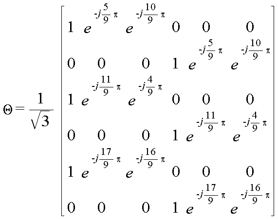
먼저, 4개의 안테나를 사용하는 Alamouti FDFR SFBC 시스템에서는 하기 <수학식 14>과 같은 선부호화 행렬(

Figure 112004026433680-pat00128
)을 사용할수 있다.First, in an Alamouti FDFR SFBC system using four antennas, a precoding matrix such as
Figure 112004026433680-pat00128
) Can be used.

Figure 112004026433680-pat00129

여기서, 상기

Figure 112004026433680-pat00130
은 각각
Figure 112004026433680-pat00131
을 만족한다.Where
Figure 112004026433680-pat00130
Are each
Figure 112004026433680-pat00131
To satisfy.

다음으로, 6개의 안테나를 사용하는 Alamouti FDFR SFBC 시스템에서는 하기 <수학식 15>과 같은 선부호화 행렬(

Figure 112004026433680-pat00132
)을 사용할수 있다. Next, in the Alamouti FDFR SFBC system using six antennas, a precoding matrix such as
Figure 112004026433680-pat00132
) Can be used.

Figure 112004026433680-pat00133

한편, 8개 이상의 안테나를 사용하는 Alamouti FDFR SFBC 시스템에서는 하기 <수학식 16>와 같은 선부호화 행렬(

Figure 112004026433680-pat00134
)을 사용할수 있다.Meanwhile, in an Alamouti FDFR SFBC system using eight or more antennas, a precoding matrix such as
Figure 112004026433680-pat00134
) Can be used.

Figure 112006002234023-pat00319

여기서,

Figure 112004026433680-pat00136
이다.
here,
Figure 112004026433680-pat00136
to be.

그러면, 여기서 도 5와 같은 송신기의 동작을 살펴보기로 한다.Then, the operation of the transmitter as shown in FIG. 5 will be described.

도 7은 본 발명의 실시예에 따른 복수의 송신안테나들을 사용하며, 주파수 공간 블록 부호화 방식을 사용하는 OFDM 이동통신시스템에서 송신기의 송신 절차를 도시하고 있다. 이하 송신안테나가 4개인 경우를 가정하여 설명하기로 한다.7 illustrates a transmission procedure of a transmitter in an OFDM mobile communication system using a plurality of transmission antennas according to an embodiment of the present invention and using a frequency space block coding scheme. In the following description, it is assumed that there are four transmission antennas.

도 7을 참조하면, 먼저 송신기는 700단계에서 전송하고자 하는 데이터열 x(

Figure 112006002234023-pat00137
)을 입력받는다. 여기서, 상기 데이터열은 부호화(encoding)와 변조(modulation)를 통해 생성된 복소심볼열이 될 수 있다. 이후, 상기 송신기의 선부호화기는 702단계에서 상기 입력받은 데이터열을 미리 설정된 선부호화 행렬(
Figure 112006002234023-pat00320
)을 이용해 부호화하여 선부호화 심볼열 r(
Figure 112006002234023-pat00138
)을 생성한다. 여기서, 상기 선부호화 행렬(
Figure 112006002234023-pat00139
)은 앞서 설명한 바와 같이 Vandermonde 행렬의 반을 천공하고 소정 행들을 쉬프트하여 구해진 행렬로, 상기 선부호화 행렬을 사용할 경우 행렬의 반이 천공되었기 때문에 부호화 및 복호화 복잡도를 현저히 줄 일수 있다. Referring to FIG. 7, first, the transmitter transmits a data string x (
Figure 112006002234023-pat00137
) Is inputted. The data string may be a complex symbol string generated through encoding and modulation. In operation 702, the pre-encoder of the transmitter converts the received data sequence into a pre-encoding matrix (
Figure 112006002234023-pat00320
) To encode the precoded symbol string r (
Figure 112006002234023-pat00138
). Here, the precoding matrix (
Figure 112006002234023-pat00139
) Is a matrix obtained by puncturing half of the Vandermonde matrix and shifting predetermined rows. When the precoding matrix is used, half of the matrix is punctured, thereby significantly reducing encoding and decoding complexity.

상기 선부호화 심볼열 (r)을 생성한후, 상기 송신기의 인코더는 704단계에서 상기 심볼열(r)을 구성하는 심볼들을 2개씩 묶어서 2개의 벡터들(

Figure 112006002234023-pat00140
)을 생성한다. After generating the pre-coded symbol string r, the encoder of the transmitter binds two symbols constituting the symbol string r by two vectors (step 704).
Figure 112006002234023-pat00140
).

그리고, 상기 송신기의 인코더는 706단계에서 상기 2개의 벡터들을 Alamouti 방식을 이용해 부호화하여 주파수 공간 사상을 수행한다. 이 과정에서 4개의 안테나 신호들이 생성된다. 상기 4개의 안테나 신호들은 앞서 <수학식 7>에서 살펴본 바와 같이

Figure 112006002234023-pat00141
,
Figure 112006002234023-pat00142
,
Figure 112006002234023-pat00143
,
Figure 112006002234023-pat00144
이다. 여기서, 하나의 안테나 신호를 구성하는 4개의 심볼들(Null 포함)은 소정 인접된 4개의 부반송파들에 할당된다.In step 706, the encoder of the transmitter encodes the two vectors using an Alamouti method to perform frequency space mapping. In this process, four antenna signals are generated. As described above in Equation 7, the four antenna signals
Figure 112006002234023-pat00141
,
Figure 112006002234023-pat00142
,
Figure 112006002234023-pat00143
,
Figure 112006002234023-pat00144
to be. Here, four symbols (including null) constituting one antenna signal are allocated to four adjacent subcarriers.

상기 4개의 안테나 신호들을 생성한후, 상기 송신기는 708단계에서 4개의 안테나 신호들 각각을 부반송파에 할당하여 역 고속 푸리에 변환(IFFT : Inverse Fast Fourier Transform)하고, 상기 역 고속 푸리에 변환된 신호들을 각각 래디오 RF(Radio Frequency) 신호로 변환하여 OFDM 변조를 수행한다. 이후, 상기 송신기는 710단계에서 상기 RF변조된 신호들을 각각 해당 안테나를 통해 송신한다.After generating the four antenna signals, the transmitter allocates each of the four antenna signals to a subcarrier in step 708 to perform an Inverse Fast Fourier Transform (IFFT), and respectively performs the inverse Fast Fourier transform signals. OFDM modulation is performed by converting into a radio frequency (Radio Frequency) signal. In step 710, the transmitter transmits the RF modulated signals through a corresponding antenna.

구체적으로, 상기

Figure 112004026433680-pat00145
을 소정 인접된 4개의 부반송파들에 할당하여 OFDM변조하고, 상기 OFDM변조된 신호를 제1송신안테나(512)를 통해 송신한다. 상기
Figure 112004026433680-pat00146
을 소정 인접된 4개의 부반송파들에 할당하여 OFDM변조하고, 상기 OFDM변조된 신호를 제2송신안테나(514)를 통해 송신한다. 상기
Figure 112004026433680-pat00147
을 소정 인접된 4개의 부반송파들에 할당하여 OFDM변조하고, 상기 OFDM변조된 신호를 제3송신안테나(516)룰 통해 송신한다. 상기
Figure 112004026433680-pat00148
을 소정 인접된 4개의 부반송파들에 할당하여 OFDM변조하고, 상기 OFDM변조된 신호를 제4송신안테나(518)룰 통해 송신한다.
Specifically, the
Figure 112004026433680-pat00145
Is allocated to four neighboring subcarriers and OFDM modulated, and the OFDM modulated signal is transmitted through the first transmission antenna 512. remind
Figure 112004026433680-pat00146
Is allocated to four adjacent subcarriers and OFDM modulated, and the OFDM modulated signal is transmitted through the second transmission antenna 514. remind
Figure 112004026433680-pat00147
Is allocated to four adjacent subcarriers and OFDM modulated, and the OFDM modulated signal is transmitted through a third transmission antenna 516 rule. remind
Figure 112004026433680-pat00148
Is allocated to four adjacent subcarriers and OFDM modulated, and the OFDM modulated signal is transmitted through a fourth transmission antenna 518 rule.

그러면, 이하에서 상기 도 5의 송신기에 대응하는 수신기에 대해 살펴보기로 한다. Next, a receiver corresponding to the transmitter of FIG. 5 will be described below.

도 8은 본 발명의 일 실시예에 따른 주파수 공간 블록 부호화 방식을 사용하는 OFDM 이동통신시스템에서 수신기의 구성을 도시하고 있다. 이하 송신기의 송신안테나가 4개인 경우를 가정하여 설명하기로 한다.8 illustrates a configuration of a receiver in an OFDM mobile communication system using a frequency space block coding scheme according to an embodiment of the present invention. Hereinafter, it will be described on the assumption that there are four transmission antennas of the transmitter.

도시된 바와 같이, 본 발명에 따른 수신기는, 복수의 수신안테나들(800 내지 802), 복수의 OFDM복조기들(804 내지 806), 채널추정기(channel estimator)(808), 채널응답행렬 생성기(810), 신호결합기(signal combiner)(812), 제1신호결정기(814) 및 제2신호결정기(815)를 포함하여 구성된다. 여기서, 상기 수신안테나의 개수와 송신기의 송신안테나 개수가 상이한 경우를 가정하지만, 상기 송신기의 송신안테나 개수와 수신기의 수신안테나 개수는 동일할수 있음은 물론이 다.As shown, the receiver according to the present invention includes a plurality of reception antennas 800 to 802, a plurality of OFDM demodulators 804 to 806, a channel estimator 808, and a channel response matrix generator 810. ), A signal combiner 812, a first signal determiner 814, and a second signal determiner 815. Here, it is assumed that the number of the reception antennas and the number of transmission antennas of the transmitter are different, but the number of transmission antennas of the transmitter and the number of reception antennas of the receiver may be the same.

도 8을 참조하면, 먼저 송신기의 송신안테나들(512 내지 518)을 통해 송신된 신호는 제1수신안테나(800) 내지 제P수신안테나(802) 각각을 통해 수신된다. 상기 제1수신안테나(800) 내지 제P수신안테나(802) 각각은 수신된 신호를 대응되는 OFDM변조기로 출력한다. Referring to FIG. 8, a signal transmitted through transmission antennas 512 to 518 of a transmitter is first received through each of the first receiving antennas 800 to P receiving antennas 802. Each of the first receiving antenna 800 to the P receiving antenna 802 outputs the received signal to a corresponding OFDM modulator.

상기 OFDM복조기들(804 내지 806) 각각은 대응되는 수신안테나로부터의 수신신호를 기저대역 신호로 변환하고, 상기 기저대역 신호를 고속 푸리에 변환(FFT : Fast Fourier Transform)하여 OFDM 복조를 수행한다. 상기 OFDM복조기들(804 내지 806) 각각은 상기 OFDM복조된 데이터를 상기 채널 추정기(808)와 상기 신호 결합기(812)로 출력한다.Each of the OFDM demodulators 804 to 806 converts a received signal from a corresponding reception antenna into a baseband signal, and performs the OFDM demodulation by performing a Fast Fourier Transform (FFT) of the baseband signal. Each of the OFDM demodulators 804 to 806 outputs the OFDM demodulated data to the channel estimator 808 and the signal combiner 812.

상기 채널 추정기(808)는 상기 OFDM복조기들(804 내지 806)로부터의 OFDM복조된 데이터들을 가지고 채널 이득(channel gain)을 나타내는 채널 계수들(channel coefficients)을 추정한다. 상기 추정된 채널 계수들은 상기 채널응답행렬 생성기(810)로 제공된다.The channel estimator 808 estimates channel coefficients representing channel gain with the OFDM demodulated data from the OFDM demodulators 804-806. The estimated channel coefficients are provided to the channel response matrix generator 810.

여기서, 상기 수신기의 수신안테나 개수를 1개라고 가정하면, 상기 1개의 수신안테나를 통해서 수신된 신호는 하기 <수학식 17>와 같이 나타낼 수 있다.Here, assuming that the number of reception antennas of the receiver is one, a signal received through the one reception antenna may be represented by Equation 17 below.

Figure 112004026433680-pat00149

여기서, 상기

Figure 112006002234023-pat00150
는 수신안테나를 통해 수신된 수신벡터를 나타내고, 상기
Figure 112006002234023-pat00151
는 채널 계수 행렬을 나타내며, 상기
Figure 112006002234023-pat00321
는 선부호화 행렬을 나타내고, 상기
Figure 112006002234023-pat00152
은 잡음(noise)벡터를 나타낸다. Where
Figure 112006002234023-pat00150
Denotes a reception vector received through the reception antenna, and
Figure 112006002234023-pat00151
Represents a channel coefficient matrix,
Figure 112006002234023-pat00321
Represents a precoding matrix,
Figure 112006002234023-pat00152
Denotes a noise vector.

상기 채널 추정기(808)는 상기 <수학식 17>와 같은 수신 신호

Figure 112006002234023-pat00153
을 입력하여 채널 추정하고, 상기 채널 추정 결과(채널 계수들)를 상기 채널응답행렬 생성기(810)로 출력한다. 상기 채널 응답 행렬 생성기(810)는 상기 채널 추정기(808)로부터의 채널 계수들을 가지고 하기 <수학식 18>와 같은 채널 응답 행렬
Figure 112006002234023-pat00154
을 생성한다. 여기서, 상기 채널응답행렬
Figure 112006002234023-pat00155
는 상기 <수학식 17>로부터 알수 있듯이 채널계수행렬
Figure 112006002234023-pat00156
와 미리 알고 있는 선부호화 행렬
Figure 112006002234023-pat00157
의 곱으로 산출될수 있다. 상기 채널 응답 행렬
Figure 112006002234023-pat00158
는 상기 신호결합기(812)와 상기 신호결정기들(814, 615)로 제공된다. The channel estimator 808 receives the received signal as shown in Equation 17.
Figure 112006002234023-pat00153
To estimate the channel, and output the channel estimation result (channel coefficients) to the channel response matrix generator 810. The channel response matrix generator 810 uses the channel coefficients from the channel estimator 808 to express a channel response matrix as shown in Equation 18 below.
Figure 112006002234023-pat00154
Create Where the channel response matrix
Figure 112006002234023-pat00155
As can be seen from Equation 17, the channel coefficient matrix
Figure 112006002234023-pat00156
And the known precoding matrix
Figure 112006002234023-pat00157
It can be calculated as the product of. The channel response matrix
Figure 112006002234023-pat00158
Is provided to the signal combiner 812 and the signal determiners 814 and 615.

Figure 112004026433680-pat00159

상기 신호 결합기(812)는 상기 OFDM복조기들(804 내지 806)로부터의 OFDM복조된 데이터들과 상기 채널응답행렬 생성기(810)로부터의 채널 응답 행렬

Figure 112004026433680-pat00160
을 소정 규칙에 의해 결합하여
Figure 112004026433680-pat00161
사이즈의 벡터를 출력한다. 구체적으로, 상기 신호 결합기(812)는 상기 채널응답행렬
Figure 112004026433680-pat00162
의 허미시안 행렬
Figure 112004026433680-pat00163
을 구하고, 상기 OFDM복조기들(804 내지 806)로부터의 수신신호
Figure 112004026433680-pat00164
을 곱해 벡터
Figure 112004026433680-pat00165
을 출력한다. 이때 상기 벡터
Figure 112004026433680-pat00166
을 구성하는 심볼의 개수가
Figure 112004026433680-pat00167
라고 가정할 경우, 상기 심볼열에서 첫 번째 심볼부터
Figure 112004026433680-pat00168
번째 심볼까지는 상기 제1신호결정기(814)로 제공되고,
Figure 112004026433680-pat00169
번째 심볼부터
Figure 112004026433680-pat00170
번째 심볼까지는 상기 제2신호 결정기(815)로 제공된다.The signal combiner 812 is the OFDM demodulated data from the OFDM demodulators 804 to 806 and the channel response matrix from the channel response matrix generator 810.
Figure 112004026433680-pat00160
By a given rule
Figure 112004026433680-pat00161
Print a vector of size. Specifically, the signal combiner 812 is the channel response matrix
Figure 112004026433680-pat00162
Hermian matrix of
Figure 112004026433680-pat00163
The received signal from the OFDM demodulators 804 to 806 is obtained.
Figure 112004026433680-pat00164
Multiply by vector
Figure 112004026433680-pat00165
Outputs Where the vector
Figure 112004026433680-pat00166
The number of symbols that make up
Figure 112004026433680-pat00167
If it is assumed that, from the first symbol in the symbol string
Figure 112004026433680-pat00168
Up to the first symbol is provided to the first signal determiner 814,
Figure 112004026433680-pat00169
From the first symbol
Figure 112004026433680-pat00170
The second symbol is provided to the second signal determiner 815.

상기 제1신호결정기(814)는 상기 채널응답행렬 생성기(810)로부터의 채널응답행렬

Figure 112006002234023-pat00171
과 상기 신호결합기(812)로부터의 벡터를 가지고 예를들어 최대 유사도 복호(Maximum Likelihood decoding)를 수행하여 송신기가 송신한 심볼들을 추정하여 출력한다. 상기 제2신호결정기(815)는 상기 채널응답행렬 생성기(810)로부터의 채널응답행렬
Figure 112006002234023-pat00172
과 상기 신호결합기(812)로부터의 벡터를 가지고 최대 유사도 복호(Maximum Likelihood decoding)를 수행하여 송신기가 송신한 심볼들을 추정하여 출력한다. 이와 같이, 본 발명은 사이즈
Figure 112006002234023-pat00173
의 최대 유사도 복호를 수행하기 때문에, 사이즈
Figure 112006002234023-pat00174
의 최대 유사도 복호에 비해 계산량을 현저히 줄일 수 있다.The first signal determiner 814 is a channel response matrix from the channel response matrix generator 810.
Figure 112006002234023-pat00171
And the vector from the signal combiner 812, for example, perform maximum likelihood decoding to estimate and output the symbols transmitted by the transmitter. The second signal determiner 815 is a channel response matrix from the channel response matrix generator 810.
Figure 112006002234023-pat00172
And maximum likelihood decoding using the vector from the signal combiner 812 to estimate and output the symbols transmitted by the transmitter. As such, the present invention is size
Figure 112006002234023-pat00173
Since the maximum similarity of the decode is performed, the size
Figure 112006002234023-pat00174
Compared to the maximum similarity decoding, the computation can be significantly reduced.

여기서, 상술한 수신기의 동작을 수학적으로 정리하면 다음과 같다.Here, the operation of the above-described receiver mathematically summarized as follows.

먼저, 상기 채널응답행렬

Figure 112006002234023-pat00175
의 허미시안 행렬
Figure 112006002234023-pat00176
과 상기 채널응답행렬
Figure 112006002234023-pat00177
을 곱하면 하기 수학식 19과 같이 나타난다. First, the channel response matrix
Figure 112006002234023-pat00175
Hermian matrix of
Figure 112006002234023-pat00176
And the channel response matrix
Figure 112006002234023-pat00177
When multiplying by the following equation (19).

Figure 112004026433680-pat00179

여기서, 상기

Figure 112004026433680-pat00180
이고, Where
Figure 112004026433680-pat00180
ego,

상기

Figure 112004026433680-pat00181
이다. remind
Figure 112004026433680-pat00181
to be.

한편, 상기 신호결합기(812)에서 발생하는 상기

Figure 112004026433680-pat00182
와 상기 수신신호
Figure 112004026433680-pat00183
의 곱은 하기 <수학식 20>과 같이 나타낼 수 있다.On the other hand, the signal generated in the signal combiner 812
Figure 112004026433680-pat00182
And the received signal
Figure 112004026433680-pat00183
The product of can be expressed as Equation 20 below.

Figure 112004026433680-pat00184

상기 <수학식 20>에 나타난 바와 같이,

Figure 112004026433680-pat00185
Figure 112004026433680-pat00186
으로부터 x1과 x2를 추정할 수 있고,
Figure 112004026433680-pat00187
Figure 112004026433680-pat00188
으로부터 x3과 x4를 추정할 수 있음을 알 수 있다. 따라서, 상기 송신기가 송신한 심볼들 x1,x2,x3,x4를 추정하는 방법은 하기 <수학식 21>과 같이 나타낼 수 있다.As shown in Equation 20,
Figure 112004026433680-pat00185
Wow
Figure 112004026433680-pat00186
We can estimate x 1 and x 2 from
Figure 112004026433680-pat00187
Wow
Figure 112004026433680-pat00188
It can be seen from the equation that x 3 and x 4 can be estimated. Therefore, a method of estimating symbols x 1 , x 2 , x 3 , and x 4 transmitted by the transmitter can be expressed by Equation 21 below.

Figure 112006002234023-pat00322

여기서,

Figure 112004026433680-pat00190
이고,
Figure 112004026433680-pat00191
이며,
Figure 112004026433680-pat00192
이고,
Figure 112004026433680-pat00193
이며,
Figure 112004026433680-pat00194
이고,
Figure 112004026433680-pat00195
이며,
Figure 112004026433680-pat00196
이다. 이와 같이, 송신기가 송신한 심볼들 x1,x2,x3,x4를 x1,x2와 x3 ,x4로 분류하여 추정하는 것이 가능하다.here,
Figure 112004026433680-pat00190
ego,
Figure 112004026433680-pat00191
Is,
Figure 112004026433680-pat00192
ego,
Figure 112004026433680-pat00193
Is,
Figure 112004026433680-pat00194
ego,
Figure 112004026433680-pat00195
Is,
Figure 112004026433680-pat00196
to be. As such, it is possible to classify and estimate the symbols x 1 , x 2 , x 3 , and x 4 transmitted by the transmitter into x 1 , x 2, and x 3 , x 4 .

즉, 상기 제1 신호결정기(814)는 상술한 방식으로 x1,x2를 추정하여

Figure 112006002234023-pat00197
을 출력하고, 상기 제2신호결정기(815)는 x3,x4에 대한 추정치
Figure 112006002234023-pat00198
을 결정하여 출력한다. 이렇게 결정된 심볼들은 복조(demodulating) 및 복호(decoding)를 거쳐 원래의 정보데이터로 복원된다. That is, the first signal determiner 814 estimates x 1 , x 2 in the above-described manner.
Figure 112006002234023-pat00197
And the second signal determiner 815 estimates x 3 and x 4 .
Figure 112006002234023-pat00198
Determine and output. The symbols thus determined are restored to the original information data through demodulation and decoding.

그러면 여기서 도 8과 같은 수신기의 동작을 살펴보기로 한다.Then, the operation of the receiver as shown in FIG. 8 will be described.

도 9는 본 발명의 실시예에 따른 주파수 공간 블록 부호화 방식을 사용하는 OFDM 이동통신시스템에서 수신기의 수신 절차를 도시하고 있다.9 illustrates a reception procedure of a receiver in an OFDM mobile communication system using a frequency space block coding scheme according to an embodiment of the present invention.

도 9를 참조하면, 먼저 수신기는 911단계에서 복수의 수신안테나들을 통해 수신되는 신호들을 각각 OFDM복조하고, 상기 OFDM복조된 데이터들을 가지고 송신기와 수신기 사이의 채널 이득(channel gain)을 나타내는 채널 계수들(channel coefficients)을 추정한다.Referring to FIG. 9, first, in step 911, a receiver OFDM demodulates signals received through a plurality of reception antennas, and channel coefficients indicating channel gain between the transmitter and the receiver with the OFDM demodulated data. estimate channel coefficients.

이후, 상기 수신기는 913단계에서 상기 추정된 채널계수들을 가지고 채널 응답 행렬(

Figure 112006002234023-pat00199
)을 생성한다. 여기서, 상기 채널 응답 행렬(
Figure 112006002234023-pat00323
)은 앞서 설명한 바와 같이, 추정된 계수들을 가지고 생성된 채널계수행렬(
Figure 112006002234023-pat00324
)와 미리 결정된 선부호화 행렬(
Figure 112006002234023-pat00325
)의 곱으로 산출된다. 상기 채널 응답 행렬(
Figure 112006002234023-pat00200
)을 생성한후, 상기 수신기는 915단계에서 상기 OFDM복조된 데이터들과 상기 채널 응답 행렬(
Figure 112006002234023-pat00201
)을 소정 규칙에 의해 결합하여
Figure 112006002234023-pat00202
개의 심볼들로 구성된 벡터를 산출한다. 상기 채널 응답 행렬의 허미시안 행렬을 산출하고, 상기 허미시안 행렬과 상기 OFDM복조된 데이터를 곱하여 송신기에서 송신한 벡터를 산출한다.In step 913, the receiver uses the estimated channel coefficients as a channel response matrix (
Figure 112006002234023-pat00199
). Here, the channel response matrix (
Figure 112006002234023-pat00323
As described above, the channel coefficient matrix generated with the estimated coefficients (
Figure 112006002234023-pat00324
) And the predetermined precoding matrix (
Figure 112006002234023-pat00325
Is a product of The channel response matrix (
Figure 112006002234023-pat00200
In step 915, the receiver decodes the OFDM demodulated data and the channel response matrix (a).
Figure 112006002234023-pat00201
) By a given rule
Figure 112006002234023-pat00202
Compute a vector of symbols. A Hermithian matrix of the channel response matrix is calculated, and the vector transmitted from the transmitter is calculated by multiplying the Hermithian matrix by the OFDM demodulated data.

이후, 상기 수신기는 917단계에서 상기 벡터를 2개로 분리하고, 상기 2개의 벡터들 각각에 대하여 ML(Maximum Likelihood decoding)복호를 수행하여 송신기에서 송신한 심볼들을 결정한다. 이렇게 결정된 심볼들은 복조(demodulating) 및 복호(decoding)를 거쳐 원래의 정보데이터로 복원된다. In step 917, the receiver separates the vectors into two and performs maximum likelihood decoding (ML) decoding on each of the two vectors to determine the symbols transmitted from the transmitter. The symbols thus determined are restored to the original information data through demodulation and decoding.

이상 살펴본 바와 같이, 기존의 Vandermonde 행렬을 그대로 선부호화 행렬로 사용하면 사이즈 4의 ML복호(Maximum Likehood) 복호를 수행하여야 하지만, 본 발명에 제안하는 선부호화 행렬을 사용하면 사이즈 2의 ML복호를 수행하기 때문에 복잡도(연산량)를 현저히 줄일 수 있다. 또한, 부호화 이득을 최대화하기 위해서는 선부호화 행렬을 최적화시켜야만 한다. 앞서 언급한 바와 같이, 상기 선부호화 행렬의 최적화는 수학적 지식 또는 시뮬레이션(computer search)을 통해 가능하다.As described above, if the existing Vandermonde matrix is used as a precoding matrix as it is, it is required to perform size 4 ML decoding (Maximum Likehood) decoding. However, if the precoding matrix proposed in the present invention is used, size 2 ML decoding is performed. Therefore, the complexity (calculation amount) can be significantly reduced. In addition, the precoding matrix must be optimized to maximize the coding gain. As mentioned above, the optimization of the precoding matrix is possible through mathematical knowledge or computer search.

예들들어, 송신안테나가 4개일 때 사용되는 선부호화 행렬의 최적화를 살펴보면 다음과 같다.For example, the optimization of the precoding matrix used when there are four transmit antennas is as follows.

도 10은 본 발명에서 제안하는 선부호화 행렬(수학식 14 참조)의

Figure 112004026433680-pat00204
,
Figure 112004026433680-pat00205
에 대하여 θ0과 θ1을 0°에서 360°까지 1°씩 변화시킬 경우의 부호화 이득을 보여주는 시뮬레이션 결과 그래프이다. 10 shows a precoding matrix proposed by the present invention (see Equation 14).
Figure 112004026433680-pat00204
,
Figure 112004026433680-pat00205
The simulation result graph shows the coding gain when θ 0 and θ 1 are changed by 1 ° from 0 ° to 360 °.

도시된 바와 같이, x축은 θ0의 값을 나타내며, y축은 θ1의 값을 나타내고, z축은 부호화 이득을 나타낸다. 도면에서 굵은 선으로 표시한 지점들에서의 θ0의 값과, θ1의 값이 최대 부호화 이득을 나타낼 경우의 θ0의 값과, θ1의 값이다. 상기 도 10에 나타난 바와 같이 부호화 이득을 최대화시키기 위해서는 하기 <수학식 22>의 조건을 만족해야만 한다.As shown, the x axis represents the value of θ 0 , the y axis represents the value of θ 1 , and the z axis represents the coding gain. The value of θ 0 at the point shown by the bold line in the figure and, to the value of θ of 0 when the value of θ 1 represent the maximum coding gain, and the value of θ 1. As shown in FIG. 10, in order to maximize the coding gain, the following Equation 22 must be satisfied.

Figure 112004026433680-pat00206

따라서, 상기 <수학식 22>의 조건을 만족하는 모든 θ0, θ1의 값에 대해서 동일한 성능을 획득할 수 있음을 알 수 있으며, 따라서 본 발명에서 제안하는 선부호화 행렬에 따른 주파수공간 블록 부호의 종류는 무수히 많게 생성될 수 있음을 알 수 있다.
Accordingly, it can be seen that the same performance can be obtained for all values of θ 0 and θ 1 that satisfy the condition of Equation 22. Therefore, the frequency-space block code according to the precoding matrix proposed in the present invention. It can be seen that a large number of kinds of can be produced.

여기서, 종래기술에서 설명된 시공간 블록 부호화 방식들과 본 발명에서 제안하는 주파수 공간 블록 부호화 방식의 복호화 복잡도를 비교하면 다음과 같다.Here, the decoding complexity of the space-time block coding schemes described in the prior art and the frequency-space block coding scheme proposed by the present invention are as follows.

도 11은 본 발명에서 제안하는 주파수 공간 블록 부호화 방식과 종래기술에서 설명된 시공간 블록 부호화 방식들의 성능을 도시하는 그래프이다. 11 is a graph showing the performance of the frequency-space block coding scheme proposed in the present invention and the space-time block coding scheme described in the prior art.

특히, 본 발명에서 제안하는 주파수 공간 블록 부호화 방식과, S.M.Alamouti가 제안한 시공간 블록 부호화 방식과, 정태진·전경훈 연구팀에서 제안한 시공간 블록 부호화 방식(A-ST-CR) 및 다이버시티를 사용하지 않을 경우(No Div)의 성능 곡선을 도시하고 있다.In particular, when the space-time block coding scheme proposed by the present invention, the space-time block coding scheme proposed by SMAlamouti, and the space-time block coding scheme (A-ST-CR) and diversity proposed by Jung Tae-jin and Jeon Kyung-hoon's research team are not used ( No Div) performance curve is shown.

도시된 바와 같이, 변조 방식으로 QPSK를 사용하는 경우의 성능 곡선이며, x 축은 신호대 잡음비(SNR : signal to Noise Ratio)를 나타내고, y축은 비트 에러율(BER : Bit Error Rate)을 나타낸다. 도면에서 알수 있듯이, 동일한 채널(SNR)에서 본 발명이 제안하는 주파수 공간 블록 부호화 방식과 정태진, 전경훈 연구팀에서 제안한 시공간 블록 부호화 방식이 타 방식에 비해 비트 에러율(BER)에서 우수한 성능을 나타냄을 알수 있다. As shown, it is a performance curve when using QPSK as a modulation method, the x axis represents a signal to noise ratio (SNR), and the y axis represents a bit error rate (BER). As can be seen from the figure, it can be seen that the frequency-space block coding scheme proposed by the present invention and the space-time block coding scheme proposed by Jung Tae-jin and Chung-hoon Chung in the same channel (SNR) show better performance in bit error rate (BER) than other schemes. .

하지만, 본 발명은 앞서 설명한 바와 같이, 새로운 선부호화기를 사용함으로써 정태진, 전경훈 연구팀에서 제안한 방식에 비해 부호화 및 복호화 복잡도(연산량)를 현저히 줄이고 있다.However, the present invention, as described above, significantly reduces the coding and decoding complexity (computation amount) compared to the method proposed by Jeong Tae-jin and Jeon, Jeon-hoon's team.

예를들어, 2m의 복소 신호를 사용하는 경우를 가정하면, 정태진, 전경훈 연구팀에서 제안한 선부호화기의 경우

Figure 112004026433680-pat00207
의 복호화 복잡도를 갖는다. 그러나, 본 발명에서 제안하는 선부호화기의 경우
Figure 112004026433680-pat00208
의 복호화 복잡도를 가지므로 정태진, 전경훈 연구팀에서 제안한 선부호화기의 복호화 복잡도에 비해 복호화 복잡도가 현저히 감소됨을 알 수 있다. For example, assuming a case of using a 2 m complex signal, the case of the precoder proposed by Tae-Jin Chung and Jeon, Jeon-hoon's team
Figure 112004026433680-pat00207
Has a decoding complexity of. However, in the case of the pre-coder proposed by the present invention
Figure 112004026433680-pat00208
The decoding complexity of is significantly reduced compared to the decoding complexity of the pre-coder proposed by Jeong Tae-jin and Chung-hoon Lee.

일 예로, 상기 송신기에서 변조 방식으로 16QAM 방식을 사용한다고 가정할 경우 정태진, 전경훈 연구팀에서 제안한 선부호화기의 복호화 복잡도는

Figure 112006002234023-pat00209
이며, 본 발명에서 제안하는 선부호화기의 복호화 복잡도는
Figure 112006002234023-pat00326
이다. 따라서,
Figure 112006002234023-pat00327
의 관계를 가지므로 연산량이 현저하게 감소함을 알 수 있다. For example, assuming that the transmitter uses a 16QAM scheme as a modulation scheme, the decoding complexity of the pre-coder proposed by Tae-Jin Chung and Jeon, Kyung-Hoon,
Figure 112006002234023-pat00209
The decoding complexity of the precoder proposed by the present invention is
Figure 112006002234023-pat00326
to be. therefore,
Figure 112006002234023-pat00327
It can be seen that the amount of computation is significantly reduced because of the relation of.

한편 본 발명의 상세한 설명에서는 구체적인 실시예에 관해 설명하였으나, 본 발명의 범위에서 벗어나지 않는 한도내에서 여러 가지 변형이 가능함은 물론이다. 그러므로 본 발명의 범위는 설명된 실시예에 국한되어 정해져서는 안되며 후술하는 특허청구의 범위뿐만 아니라 이 특허청구의 범위와 균등한 것들에 의해 정해져야 한다.
Meanwhile, in the detailed description of the present invention, specific embodiments have been described, but various modifications are possible without departing from the scope of the present invention. Therefore, the scope of the present invention should not be limited to the described embodiments, but should be defined not only by the scope of the following claims, but also by the equivalents of the claims.

상술한 바와 같이, 본 발명은 OFDM(Orthogonal Frequency Division Multiplexing) 시스템에 적용하기 위한 주파수 공간 블록 부호화(SFBC : Space Frequency Block Coding) 방식을 제안하고 있다. 특히, 본 발명에 따른 주파수 공간 블록 부호화 방식은 최대 다이버시티 이득 및 최대 전송률을 지원하면서 부호화 및 복호화 복잡도(연산량)를 최소화하는 이점을 가진다. As described above, the present invention proposes a space frequency block coding (SFBC) scheme for applying to an orthogonal frequency division multiplexing (OFDM) system. In particular, the frequency-space block coding scheme according to the present invention has an advantage of minimizing encoding and decoding complexity (operation amount) while supporting maximum diversity gain and maximum data rate.

Claims (66)

삭제delete 삭제delete 삭제delete 삭제delete 삭제delete 삭제delete 삭제delete 삭제delete 삭제delete 삭제delete 삭제delete 삭제delete 삭제delete 삭제delete 삭제delete 삭제delete 삭제delete 삭제delete 삭제delete 삭제delete 복수(
Figure 112007026601826-pat00212
)의 송신안테나들을 사용하는 통신시스템의 송신기 장치에 있어서,
revenge(
Figure 112007026601826-pat00212
A transmitter apparatus of a communication system using transmission antennas of
단일행렬(unitary matrix)을 천공한 선부호화 행렬을 이용하여 입력 심볼열을 선부호화하는 선부호화기와,A pre-encoder for pre-coding an input symbol sequence by using a pre-encoding matrix having a unitary matrix perforated; 상기 선부호화기로부터의 심볼열을 부호화 행렬을 이용해 주파수 공간 부호화하는 인코더를 포함하는 것을 특징으로 하는 장치.And an encoder for frequency-space encoding the symbol string from the precoder using an encoding matrix.
제21항에 있어서,The method of claim 21, 상기 인코더는 상기 선부호화기로부터의 심볼열을 2개씩 묶어 복수의 벡터들을 구성하고, 상기 복수의 벡터들 각각을 알라모우티(Alamouti) 부호화하여 주파수-공간 사상된 심볼들 각각을 대응되는 OFDM변조기로 출력하는 것을 특징으로 하는 장치.The encoder configures a plurality of vectors by tying two symbol strings from the pre-encoder, and outputs each of the frequency-space mapped symbols to a corresponding OFDM modulator by Alamouti coding each of the plurality of vectors. Device characterized in that. 제21항에 있어서,The method of claim 21, 상기 주파수 공간 부호화를 위한 부호화 행렬은 하기 수식과 같은 것을 특징으로 하는 장치.The coding matrix for the frequency space coding is characterized in that the following formula.
Figure 112007026601826-pat00328
여기서,
Figure 112007026601826-pat00329
는 선부호화기의 출력 심볼들을 나타내고, 상기 행렬
Figure 112007026601826-pat00330
Figure 112007026601826-pat00331
번째 행(row)은 매핑 시작점으로부터
Figure 112007026601826-pat00332
번째 부반송파에 사상되고,
Figure 112007026601826-pat00333
번째 열(column)은
Figure 112007026601826-pat00334
번째 안테나에 사상됨.
here,
Figure 112007026601826-pat00329
Denotes output symbols of the precoder, and the matrix
Figure 112007026601826-pat00330
of
Figure 112007026601826-pat00331
The first row is from the start of the mapping
Figure 112007026601826-pat00332
Is mapped to the first subcarrier,
Figure 112007026601826-pat00333
The first column is
Figure 112007026601826-pat00334
Mapped to the first antenna.
제21항에 있어서,The method of claim 21, 상기 인코더로부터의 복수의 벡터들 각각을 소정 인접된 부반송파들에 할당하여 역 고속 푸리에 변환하고 RF(Radio Frequency)신호로 변환하여 대응되는 안테나를 통해 송신하기 위한 복수의 OFDM(Orthogonal Frequency Division Multiplexing)변조기들을 더 포함하는 것을 특징으로 하는 장치.A plurality of orthogonal frequency division multiplexing (OFDM) modulators for allocating each of the plurality of vectors from the encoder to predetermined adjacent subcarriers, inverse fast Fourier transform, converting to a Radio Frequency (RF) signal, and transmitting them through a corresponding antenna The apparatus further comprises a. 제24항에 있어서,The method of claim 24, 전송데이터를 부호화하여 부호심볼들을 발생하는 부호기와,An encoder for encoding coded data to generate code symbols, 상기 부호기로부터의 부호심볼들을 변조하여 상기 선부호화기로 제공하는 변조기를 더 포함하는 것을 특징으로 하는 장치.And a modulator for modulating code symbols from the encoder and providing the code symbols to the pre-encoder. 제21항에 있어서,The method of claim 21, 상기 선부호화 행렬은,
Figure 112006002234023-pat00335
의 Vandermonde 행렬에서
Figure 112006002234023-pat00336
개의 열들을 천공하고, 상기 천공된 행렬에 대해 행들을 순차로 2개씩 그룹화하며, 상기 그룹화된 2개의 행들중 하나를 쉬프트한 행렬인 것을 특징으로 하는 장치.
The precoding matrix is
Figure 112006002234023-pat00335
In the Vandermonde procession
Figure 112006002234023-pat00336
Perforating two columns, grouping rows two by one for the perforated matrix, and shifting one of the grouped two rows.
제21항에 있어서,The method of claim 21, 상기 송신 안테나의 개수(
Figure 112006002234023-pat00337
)가 4개일 경우, 상기 선부호화 행렬은 하기 수식과 같은 것을 특징으로 하는 장치.
Number of transmission antennas (
Figure 112006002234023-pat00337
) Is 4, the precoding matrix is characterized in that the following formula.
Figure 112006002234023-pat00338
여기서,
Figure 112006002234023-pat00339
이고,
Figure 112006002234023-pat00340
임.
here,
Figure 112006002234023-pat00339
ego,
Figure 112006002234023-pat00340
being.
제21항에 있어서,The method of claim 21, 상기 송신 안테나의 개수(
Figure 112006002234023-pat00341
)가 6개일 경우, 상기 선부호화 행렬은 하기 수식과 같은 것을 특징으로 하는 장치.
Number of transmission antennas (
Figure 112006002234023-pat00341
) Is 6, the precoding matrix is characterized in that the following formula.
Figure 112006002234023-pat00342
제21항에 있어서,The method of claim 21, 상기 송신 안테나의 개수(
Figure 112006002234023-pat00343
)가 짝수개일 경우, 상기 선부호화 행렬은 하기 수식과 같은 것을 특징으로 하는 장치.
Number of transmission antennas (
Figure 112006002234023-pat00343
) Is an even number, the precoding matrix is characterized in that the following formula.
Figure 112006002234023-pat00344
여기서,
Figure 112006002234023-pat00345
임.
here,
Figure 112006002234023-pat00345
being.
송신 데이터를 선부호화한후 주파수 공간 부호화하는 통신시스템에서, 선부호화 행렬을 생성하기 위한 장치에 있어서,An apparatus for generating a precoding matrix in a communication system for precoding a transmission data and then performing a frequency space encoding. 단일 행렬(unitary matrix)을 생성하는 행렬생성기와,A matrix generator that creates a unitary matrix, 상기 생성된 단일 행렬에서 열들의 반을 천공하는 천공기와,A perforator to perforate half of the columns in the generated single matrix, 상기 천공된 행렬의 행들을 순차로 2개씩 그룹화하고, 상기 그룹화된 2개의 행들중 하나를 쉬프트하여 상기 선부호화 행렬을 생성하는 쉬프트기를 포함하는 것을 특징으로 하는 장치.And a shifter for grouping the rows of the perforated matrix sequentially two by two and shifting one of the two grouped rows to produce the precoding matrix. 제30항에 있어서,The method of claim 30, 상기 단일 행렬은 "Vandermonde" 행렬인 것을 특징으로 하는 장치.Wherein said single matrix is a "Vandermonde" matrix. 제30항에 있어서,The method of claim 30, 송신 안테나의 개수가 '4'개일 경우, 상기 선부호화 행렬은 하기 수식과 같은 것을 특징으로 하는 장치.And when the number of transmitting antennas is '4', the precoding matrix is characterized by the following equation.
Figure 112006002234023-pat00346
여기서,
Figure 112006002234023-pat00347
이고,
Figure 112006002234023-pat00348
임.
here,
Figure 112006002234023-pat00347
ego,
Figure 112006002234023-pat00348
being.
제30항에 있어서,The method of claim 30, 송신 안테나의 개수가 '6'개일 경우, 상기 선부호화 행렬은 하기 수식과 같은 것을 특징으로 하는 장치.And when the number of transmit antennas is '6', the precoding matrix is characterized by the following equation.
Figure 112006002234023-pat00349
제30항에 있어서,The method of claim 30, 송신 안테나의 개수가
Figure 112007026601826-pat00350
라 할때, 상기 선부호화 행렬은 하기 수식과 같은 것을 특징으로 하는 장치.
The number of transmit antennas
Figure 112007026601826-pat00350
The precoding matrix is characterized in that the following formula.
Figure 112007026601826-pat00351
여기서,
Figure 112007026601826-pat00352
임.
here,
Figure 112007026601826-pat00352
being.
송신기가 복수(
Figure 112006002234023-pat00353
)의 송신안테나들을 사용하는 통신시스템에서 수신기 장치에 있어서,
Multiple transmitters
Figure 112006002234023-pat00353
A receiver device in a communication system using transmission antennas of
적어도 하나의 수신안테나를 통해 수신되는 신호를 OFDM복조하기 위한 적어도 하나의 OFDM복조기와,At least one OFDM demodulator for OFDM demodulating a signal received through at least one receiving antenna; 채널계수행렬(H)과 미리 결정된 선부호화 행렬(θ)를 곱한 채널응답행렬을 생성하는 행렬생성기와,A matrix generator for generating a channel response matrix by multiplying the channel coefficient matrix H by a predetermined precoding matrix; 상기 행렬생성기로부터의 채널응답행렬의 허미시안 행렬을 산출하고, 상기 허미시안 행렬과 상기 적어도 하나의 OFDM복조기로부터의 신호를 곱하여
Figure 112006002234023-pat00354
사이즈의 벡터를 산출하고, 상기 벡터를 2개로 분리하여 출력하는 신호 결합기를 포함하는 것을 특징으로 하는 장치.
Computing a Hermithian matrix of the channel response matrix from the matrix generator, multiplying the Hermithian matrix by a signal from the at least one OFDM demodulator
Figure 112006002234023-pat00354
And a signal combiner for calculating a vector having a size and dividing the vector into two.
제35항에 있어서,36. The method of claim 35 wherein 상기 신호결합기로부터의 2개의 벡터들을 각각 소정 방식으로 복호하여 송신기가 송신한 심볼들을 추정하는 신호결정기를 더 포함하는 것을 특징으로 하는 장치.And a signal determiner for decoding the two vectors from the signal combiner in a predetermined manner, respectively, to estimate the symbols transmitted by the transmitter. 제36항에 있어서,The method of claim 36, 상기 소정 복호 방식은 최대 유사도 복호(Maximum Likehood decoding)인 것을 특징으로 하는 장치.The predetermined decoding method is characterized in that the maximum similarity decoding (Maximum Likehood decoding). 제36항에 있어서,The method of claim 36, 상기 적어도 하나의 OFDM복조기로부터의 신호를 이용해 채널계수들을 산출하여 상기 행렬생성기로 제공하는 채널추정기와,A channel estimator for calculating channel coefficients using the signals from the at least one OFDM demodulator and providing the coefficients to the matrix generator; 상기 신호결정기로부터의 추정 심볼들을 복조하기 위한 복조기와,A demodulator for demodulating estimated symbols from the signal determiner; 상기 복조기로부터의 복조심볼들을 복호하기 위한 복호기를 더 포함하는 것을 특징으로 하는 장치.And a decoder for decoding demodulation symbols from the demodulator. 제35항에 있어서,36. The method of claim 35 wherein 상기 선부호화 행렬은,
Figure 112006002234023-pat00355
의 Vandermonde 행렬에서
Figure 112006002234023-pat00356
개의 열들을 천공하고, 상기 천공된 행렬에 대해 행들을 순차로 2개씩 그룹화하며, 상기 그룹화된 2개의 행들중 하나를 쉬프트한 행렬인 것을 특징으로 하는 장치.
The precoding matrix is
Figure 112006002234023-pat00355
In the Vandermonde procession
Figure 112006002234023-pat00356
Perforating two columns, grouping rows two by one for the perforated matrix, and shifting one of the grouped two rows.
제35항에 있어서,36. The method of claim 35 wherein 상기 송신 안테나의 개수가 '4'개일 경우, 상기 선부호화 행렬은 하기 수식과 같은 것을 특징으로 하는 장치.And when the number of transmitting antennas is '4', the precoding matrix is as follows.
Figure 112006002234023-pat00357
여기서,
Figure 112006002234023-pat00358
이고,
Figure 112006002234023-pat00359
임.
here,
Figure 112006002234023-pat00358
ego,
Figure 112006002234023-pat00359
being.
제35항에 있어서,36. The method of claim 35 wherein 상기 송신 안테나의 개수가 '6'개일 경우, 상기 선부호화 행렬은 하기 수식과 같은 것을 특징으로 하는 장치.And when the number of transmitting antennas is '6', the precoding matrix is as follows.
Figure 112006002234023-pat00360
제35항에 있어서,36. The method of claim 35 wherein 상기 송신 안테나의 개수(
Figure 112006002234023-pat00361
)가 짝수일 경우, 상기 선부호화 행렬은 하기 수식과 같은 것을 특징으로 하는 장치.
Number of transmission antennas (
Figure 112006002234023-pat00361
) Is an even number, the precoding matrix is characterized by the following formula.
Figure 112006002234023-pat00362
여기서,
Figure 112006002234023-pat00363
임.
here,
Figure 112006002234023-pat00363
being.
복수(
Figure 112007026601826-pat00364
)의 송신안테나들을 사용하는 통신시스템에서 송신방법에 있어서,
revenge(
Figure 112007026601826-pat00364
In a transmission method in a communication system using a transmission antenna of
단일행렬(unitary matrix)을 천공한 선부호화 행렬을 이용하여 입력 복소심볼열을 선부호화하는 과정과,Precoding an input complex symbol string using a precoding matrix punctured by a unitary matrix; 상기 선부호화된 심볼열을 부호화 행렬을 이용해 주파수 공간 부호화하는 과정을 포함하는 것을 특징으로 하는 방법.And frequency-space encoding the precoded symbol string using a coding matrix.
제43항에 있어서,The method of claim 43, 상기 주파수 공간 부호화를 위한 부호화 행렬은 하기 수식과 같은 것을 특징으로 하는 방법.The coding matrix for the frequency space coding is characterized by the following equation.
Figure 112007026601826-pat00365
여기서,
Figure 112007026601826-pat00366
는 선부호화기의 출력 심볼들을 나타내고, 상기 행렬
Figure 112007026601826-pat00367
Figure 112007026601826-pat00368
번째 행(row)은 매핑 시작점으로부터
Figure 112007026601826-pat00369
번째 부반송파에 사상되고,
Figure 112007026601826-pat00370
번째 열(column)은
Figure 112007026601826-pat00371
번째 안테나에 사상됨.
here,
Figure 112007026601826-pat00366
Denotes output symbols of the precoder, and the matrix
Figure 112007026601826-pat00367
of
Figure 112007026601826-pat00368
The first row is from the start of the mapping
Figure 112007026601826-pat00369
Is mapped to the first subcarrier,
Figure 112007026601826-pat00370
The first column is
Figure 112007026601826-pat00371
Mapped to the first antenna.
제43항에 있어서,The method of claim 43, 상기 주파수 공간 부호화 과정을 통해 생성된 복수의 벡터들 각각을 소정 인접된 부반송파들에 할당하여 역 고속 푸리에 변환하고 RF(Radio Frequency)신호로 변환하여 대응되는 안테나를 통해 송신하기 위한 과정을 더 포함하는 것을 특징으로 하는 방법.And assigning each of the plurality of vectors generated through the frequency-space encoding process to predetermined adjacent subcarriers, inverse fast Fourier transform, converting to a radio frequency (RF) signal, and transmitting the same through a corresponding antenna. Characterized in that the method. 제45항에 있어서,The method of claim 45, 전송데이터를 부호화하여 부호심볼들을 발생하는 과정과,Generating code symbols by encoding transmission data; 상기 부호심볼들을 변조하여 상기 복소심볼열을 발생하는 과정을 더 포함하는 것을 특징으로 하는 방법.And modulating the code symbols to generate the complex symbol string. 제43항에 있어서,The method of claim 43, 상기 선부호화 행렬은,
Figure 112006002234023-pat00372
의 Vandermonde 행렬에서
Figure 112006002234023-pat00373
개의 열들을 천공하고, 상기 천공된 행렬에 대해 행들을 순차로 2개씩 그룹화하며, 상기 그룹화된 2개의 행들중 하나를 쉬프트한 행렬인 것을 특징으로 하는 방법.
The precoding matrix is
Figure 112006002234023-pat00372
In the Vandermonde procession
Figure 112006002234023-pat00373
Puncturing two columns, grouping rows two by one with respect to the punctured matrix, and shifting one of the grouped two rows.
제43항에 있어서,The method of claim 43, 송신 안테나의 개수가 '4'개일 경우, 상기 선부호화 행렬은 하기 수식과 같은 것을 특징으로 하는 방법.If the number of transmitting antennas is '4', the precoding matrix is characterized by the following equation.
Figure 112006002234023-pat00374
여기서,
Figure 112006002234023-pat00375
이고,
Figure 112006002234023-pat00376
임.
here,
Figure 112006002234023-pat00375
ego,
Figure 112006002234023-pat00376
being.
제43항에 있어서,The method of claim 43, 송신 안테나의 개수가 '6'개일 경우, 상기 선부호화 행렬은 하기 수식과 같은 것을 특징으로 하는 방법.If the number of transmit antennas is '6', the precoding matrix is characterized by the following equation.
Figure 112006002234023-pat00377
제43항에 있어서,The method of claim 43, 상기 송신 안테나의 개수가
Figure 112006002234023-pat00378
라 할때, 상기 선부호화 행렬은 하기 수식과 같은 것을 특징으로 하는 방법.
The number of transmit antennas
Figure 112006002234023-pat00378
The precoding matrix is characterized in that the following formula.
Figure 112006002234023-pat00379
여기서,
Figure 112006002234023-pat00380
임.
here,
Figure 112006002234023-pat00380
being.
송신 데이터를 선부호화한후 주파수 공간 부호화하는 통신시스템에서, 선부호화 행렬을 생성하기 위한 방법에 있어서,In a communication system for pre-coding the transmission data and then frequency-space encoding, the method for generating a pre-coding matrix, 단일 행렬(unitary matrix)을 생성하는 과정과,Creating a unitary matrix, 상기 생성된 단일 행렬에서 열들의 반을 천공하는 과정과,Puncturing half of the columns in the generated single matrix; 상기 천공된 행렬의 행들을 순차로 2개씩 그룹화하고, 상기 그룹화된 2개의 행들중 하나를 쉬프트하여 상기 선부호화 행렬을 생성하는 과정을 포함하는 것을 특징으로 하는 방법.And grouping the rows of the perforated matrix sequentially two by two, and shifting one of the two grouped rows to generate the pre-encoding matrix. 제51항에 있어서,The method of claim 51, 상기 단일 행렬은 "Vandermonde" 행렬인 것을 특징으로 하는 방법.Wherein said single matrix is a "Vandermonde" matrix. 제51항에 있어서,The method of claim 51, 송신 안테나의 개수가 '4'개일 경우, 상기 선부호화 행렬은 하기 수식과 같은 것을 특징으로 하는 방법.If the number of transmitting antennas is '4', the precoding matrix is characterized by the following equation.
Figure 112006002234023-pat00381
여기서,
Figure 112006002234023-pat00382
이고,
Figure 112006002234023-pat00383
임.
here,
Figure 112006002234023-pat00382
ego,
Figure 112006002234023-pat00383
being.
제51항에 있어서,The method of claim 51, 송신 안테나의 개수가 '6'개일 경우, 상기 선부호화 행렬은 하기 수식과 같은 것을 특징으로 하는 방법.If the number of transmit antennas is '6', the precoding matrix is characterized by the following equation.
Figure 112006002234023-pat00384
제51항에 있어서,The method of claim 51, 송신 안테나의 개수가
Figure 112007026601826-pat00385
라 할때, 상기 선부호화 행렬은 하기 수식과 같은 것을 특징으로 하는 방법.
The number of transmit antennas
Figure 112007026601826-pat00385
The precoding matrix is characterized in that the following formula.
Figure 112007026601826-pat00386
여기서,
Figure 112007026601826-pat00387
임.
here,
Figure 112007026601826-pat00387
being.
송신기가 복수(
Figure 112007026601826-pat00388
)의 송신안테나들을 사용하는 통신시스템에서 수신기의 수신방법에 있어서,
Multiple transmitters
Figure 112007026601826-pat00388
In a receiving method of a receiver in a communication system using transmission antennas of
적어도 하나의 수신안테나를 통해 수신되는 신호를 OFDM복조하기 위한 과정과,OFDM demodulating a signal received through at least one receiving antenna; 채널계수행렬(H)과 미리 결정된 선부호화 행렬(θ)을 곱한 채널응답행렬을 생성하는 과정과,Generating a channel response matrix by multiplying the channel coefficient matrix (H) by a predetermined precoding matrix (θ); 상기 채널응답행렬의 허미시안 행렬을 산출하는 과정과,Calculating a hermitian matrix of the channel response matrix; 상기 허미시안 행렬과 상기 OFDM복조된 신호를 곱하여
Figure 112007026601826-pat00389
사이즈의 벡터를 산출하고, 상기 벡터를 2개로 분리하는 과정과,
Multiplying the Hermithian matrix by the OFDM demodulated signal
Figure 112007026601826-pat00389
Calculating a vector of a size, separating the vector into two,
상기 분리된 2개의 벡터들을 각각 소정 방식으로 복호하여 송신기가 송신한 심볼들을 추정하는 과정을 포함하는 것을 특징으로 하는 방법.And decoding the separated two vectors in a predetermined manner to estimate symbols transmitted by a transmitter.
제56항에 있어서,The method of claim 56, wherein 상기 소정 복호 방식은 최대 유사도 복호(Maximum Likehood decoding)인 것을 특징으로 하는 방법.The predetermined decoding method is characterized in that the maximum likelihood decoding (Maximum Likehood decoding). 제56항에 있어서,The method of claim 56, wherein 상기 OFDM복조된 신호를 이용해 채널계수들을 산출하여 상기 채널계수행렬을 생성하는 과정과,Generating channel coefficient matrix by calculating channel coefficients using the OFDM demodulated signal; 상기 추정된 심볼들을 복조하여 복조심볼들을 생성하는 과정과,Demodulating the estimated symbols to generate demodulation symbols; 상기 복조심볼들을 복호하여 원래의 정보데이터로 복원하는 과정을 더 포함하는 것을 특징으로 하는 방법.And decoding the demodulation symbols and restoring the original information data. 제56항에 있어서,The method of claim 56, wherein 상기 선부호화 행렬은,
Figure 112006002234023-pat00390
의 Vandermonde 행렬에서
Figure 112006002234023-pat00391
개의 열들을 천공하고, 상기 천공된 행렬에 대해 행들을 순차로 2개씩 그룹화하며, 상기 그룹화된 2개의 행들중 하나를 쉬프트한 행렬인 것을 특징으로 하는 방법.
The precoding matrix is
Figure 112006002234023-pat00390
In the Vandermonde procession
Figure 112006002234023-pat00391
Puncturing two columns, grouping rows two by one with respect to the punctured matrix, and shifting one of the grouped two rows.
제56항에 있어서,The method of claim 56, wherein 송신 안테나의 개수(
Figure 112006002234023-pat00392
)가 '4'개일 경우, 상기 선부호화 행렬은 하기 수식과 같은 것을 특징으로 하는 방법.
Number of transmit antennas (
Figure 112006002234023-pat00392
) Is '4', the precoding matrix is characterized by the following formula.
Figure 112006002234023-pat00393
여기서,
Figure 112006002234023-pat00394
이고,
Figure 112006002234023-pat00395
임.
here,
Figure 112006002234023-pat00394
ego,
Figure 112006002234023-pat00395
being.
제56항에 있어서,The method of claim 56, wherein 송신 안테나의 개수(
Figure 112006002234023-pat00396
)가 '6'개일 경우, 상기 선부호화 행렬은 하기 수식과 같은 것을 특징으로 하는 방법.
Number of transmit antennas (
Figure 112006002234023-pat00396
) Is '6', the precoding matrix is characterized by the following formula.
Figure 112006002234023-pat00397
제56항에 있어서,The method of claim 56, wherein 상기 송신 안테나의 개수(
Figure 112006002234023-pat00398
) 짝수일 때, 상기 선부호화 행렬은 하기 수식과 같은 것을 특징으로 하는 방법.
Number of transmission antennas (
Figure 112006002234023-pat00398
When the even number, the precoding matrix is characterized by the following formula.
Figure 112006002234023-pat00399
여기서,
Figure 112006002234023-pat00400
임.
here,
Figure 112006002234023-pat00400
being.
복수(
Figure 112007026601826-pat00401
)의 송신안테나들을 사용하는 직교주파수분할다중 통신시스템의 송신기 장치에 있어서,
revenge(
Figure 112007026601826-pat00401
A transmitter apparatus of an orthogonal frequency division multiple communication system using transmission antennas of
단일행렬(unitary matrix)을 천공한 선부호화 행렬을 이용하여 입력 심볼열을 선부호화하는 선부호화기와,A pre-encoder for pre-coding an input symbol sequence by using a pre-encoding matrix having a unitary matrix perforated; 상기 선부호화기로부터의 심볼열을 부호화 행렬을 이용해 주파수 공간 부호화하는 인코더를 포함하는 것을 특징으로 하는 장치.And an encoder for frequency-space encoding the symbol string from the precoder using an encoding matrix.
송신기가 복수(
Figure 112006002234023-pat00402
)의 송신안테나들을 사용하는 직교주파수분할다중 통신시스템에서 수신기 장치에 있어서,
Multiple transmitters
Figure 112006002234023-pat00402
A receiver device in an orthogonal frequency division multiple communication system using transmission antennas of
적어도 하나의 수신안테나를 통해 수신되는 신호를 OFDM복조하기 위한 적어도 하나의 OFDM복조기와,At least one OFDM demodulator for OFDM demodulating a signal received through at least one receiving antenna; 채널계수행렬(H)과 미리 결정된 선부호화 행렬(θ)를 곱한 채널응답행렬을 생성하는 행렬생성기와,A matrix generator for generating a channel response matrix by multiplying the channel coefficient matrix H by a predetermined precoding matrix; 상기 행렬생성기로부터의 채널응답행렬의 허미시안 행렬을 산출하고, 상기 허미시안 행렬과 상기 적어도 하나의 OFDM복조기로부터의 신호를 곱하여
Figure 112006002234023-pat00403
사이즈의 벡터를 산출하고, 상기 벡터를 2개로 분리하여 출력하는 신호 결합기를 포함하는 것을 특징으로 하는 장치.
Computing a Hermithian matrix of the channel response matrix from the matrix generator, multiplying the Hermithian matrix by a signal from the at least one OFDM demodulator
Figure 112006002234023-pat00403
And a signal combiner for calculating a vector having a size and dividing the vector into two.
복수(
Figure 112007026601826-pat00404
)의 송신안테나들을 사용하는 직교주파수분할다중 통신시스템에서 송신방법에 있어서,
revenge(
Figure 112007026601826-pat00404
In a transmission method in an orthogonal frequency division multiple communication system using transmission antennas of
단일행렬(unitary matrix)을 천공한 선부호화 행렬을 이용하여 입력 복소심볼열을 선부호화하는 과정과,Precoding an input complex symbol string using a precoding matrix punctured by a unitary matrix; 상기 선부호화된 심볼열을 부호화 행렬을 이용해 주파수 공간 부호화하는 과정을 포함하는 것을 특징으로 하는 방법.And frequency-space encoding the precoded symbol string using a coding matrix.
송신기가 복수(
Figure 112007026601826-pat00405
)의 송신안테나들을 사용하는 직교주파수분할다중 통신시스템에서 수신기의 수신방법에 있어서,
Multiple transmitters
Figure 112007026601826-pat00405
A receiving method of a receiver in an orthogonal frequency division multiple communication system using transmission antennas of
적어도 하나의 수신안테나를 통해 수신되는 신호를 OFDM복조하기 위한 과정과,OFDM demodulating a signal received through at least one receiving antenna; 채널계수행렬(H)과 미리 결정된 선부호화 행렬(θ)을 곱한 채널응답행렬을 생성하는 과정과,Generating a channel response matrix by multiplying the channel coefficient matrix (H) by a predetermined precoding matrix (θ); 상기 채널응답행렬의 허미시안 행렬을 산출하는 과정과,Calculating a hermitian matrix of the channel response matrix; 상기 허미시안 행렬과 상기 OFDM복조된 신호를 곱하여
Figure 112007026601826-pat00406
사이즈의 벡터를 산출하고, 상기 벡터를 2개로 분리하는 과정과,
Multiplying the Hermithian matrix by the OFDM demodulated signal
Figure 112007026601826-pat00406
Calculating a vector of a size, separating the vector into two,
상기 분리된 2개의 벡터들을 각각 복호(decoding)하여 송신기가 송신한 심볼들을 추정하는 과정을 포함하는 것을 특징으로 하는 방법.And decoding the separated two vectors, respectively, to estimate the symbols transmitted by the transmitter.
KR1020040045526A 2004-06-18 2004-06-18 Apparatus and method for encoding/decoding space frequency block code for orthogonal frequency division multiplexing system KR100754795B1 (en)

Priority Applications (7)

Application Number Priority Date Filing Date Title
KR1020040045526A KR100754795B1 (en) 2004-06-18 2004-06-18 Apparatus and method for encoding/decoding space frequency block code for orthogonal frequency division multiplexing system
CN2005800199067A CN1969522B (en) 2004-06-18 2005-06-18 Apparatus and method for space-frequency block coding/decoding in a communication system
PCT/KR2005/001897 WO2005125140A1 (en) 2004-06-18 2005-06-18 Apparatus and method for space-frequency block coding/decoding in a communication system
JP2007516401A JP4468446B2 (en) 2004-06-18 2005-06-18 Apparatus and method for encoding / decoding frequency space block code in orthogonal frequency division multiplexing system
US11/156,689 US7606320B2 (en) 2004-06-18 2005-06-20 Apparatus and method for space-frequency block coding/decoding in a communication system
EP05013272A EP1608081B1 (en) 2004-06-18 2005-06-20 Apparatus and method for space-frequency block coding/decoding in a communication system
DE602005014307T DE602005014307D1 (en) 2004-06-18 2005-06-20 Apparatus and method for space frequency block coding / decoding in a communication system

Applications Claiming Priority (1)

Application Number Priority Date Filing Date Title
KR1020040045526A KR100754795B1 (en) 2004-06-18 2004-06-18 Apparatus and method for encoding/decoding space frequency block code for orthogonal frequency division multiplexing system

Publications (2)

Publication Number Publication Date
KR20050120244A KR20050120244A (en) 2005-12-22
KR100754795B1 true KR100754795B1 (en) 2007-09-03

Family

ID=35124490

Family Applications (1)

Application Number Title Priority Date Filing Date
KR1020040045526A KR100754795B1 (en) 2004-06-18 2004-06-18 Apparatus and method for encoding/decoding space frequency block code for orthogonal frequency division multiplexing system

Country Status (7)

Country Link
US (1) US7606320B2 (en)
EP (1) EP1608081B1 (en)
JP (1) JP4468446B2 (en)
KR (1) KR100754795B1 (en)
CN (1) CN1969522B (en)
DE (1) DE602005014307D1 (en)
WO (1) WO2005125140A1 (en)

Families Citing this family (87)

* Cited by examiner, † Cited by third party
Publication number Priority date Publication date Assignee Title
WO2005075943A1 (en) * 2004-01-07 2005-08-18 Philips Intellectual Property & Standards Gmbh Amr sensor element for angle measurement
KR100671231B1 (en) * 2004-06-21 2007-02-28 삼성전자주식회사 APPARATUS AND METHOD OF SPACE TIME BLOCK CODE FOR even TX ANTENNAS WITH FULL RATE AND FULL DIVERSITY
US8023589B2 (en) 2004-08-09 2011-09-20 Texas Instruments Incorporated Wireless MIMO transmitter with antenna and tone precoding blocks
US8130855B2 (en) * 2004-11-12 2012-03-06 Interdigital Technology Corporation Method and apparatus for combining space-frequency block coding, spatial multiplexing and beamforming in a MIMO-OFDM system
US7593475B2 (en) * 2005-06-29 2009-09-22 Broadcom Corporation Space-time and/or space-frequency block coding using complex signal swapping
KR101276797B1 (en) 2005-08-24 2013-06-20 한국전자통신연구원 Base station tranmitter for mobile telecommunication system, method for that system
TWI562572B (en) 2006-01-11 2016-12-11 Interdigital Tech Corp Method and apparatus for implementing space time processing with unequal modulation and coding schemes
KR20070076642A (en) * 2006-01-19 2007-07-25 삼성전자주식회사 Apparatus and method for orthogonalized spatial multiplexing in closed loop mimo-ofdm system
CN101026433B (en) * 2006-02-24 2010-08-25 上海无线通信研究中心 Signal-to-noise ration estimation method for adaptive modulating-coding
KR101260835B1 (en) * 2006-02-28 2013-05-06 삼성전자주식회사 Apparatus and method for transceiving a signal in a multi antenna system
KR100950645B1 (en) * 2006-03-03 2010-04-01 삼성전자주식회사 Apparatus and method for transmitting/receiving a signal in a mobile communication system using multiple input multiple output scheme
CN101043298B (en) * 2006-03-20 2011-07-27 华为技术有限公司 Method and system for transmitting signal in multi-antenna communication
US7668268B2 (en) * 2006-05-22 2010-02-23 Nokia Corporation Lower complexity computation of lattice reduction
TWI343200B (en) * 2006-05-26 2011-06-01 Lg Electronics Inc Method and apparatus for signal generation using phase-shift based pre-coding
KR20070113967A (en) * 2006-05-26 2007-11-29 엘지전자 주식회사 Phase shift based precoding method and tranceiver supporting the same
US8121209B2 (en) 2006-07-25 2012-02-21 Marvell World Trade Ltd. Concatenation-assisted symbol-level combining for MIMO systems with HARQ and/or repetition coding
US8929472B1 (en) 2006-07-26 2015-01-06 Marvell International Ltd. Bit-level combining for MIMO systems with HARQ and/or repetition coding
US8090063B2 (en) 2006-07-26 2012-01-03 Marvell World Trade Ltd. Symbol-level combining for multiple input multiple output (MIMO) systems with hybrid automatic repeat request (HARQ) and/or repetition coding
US8027402B2 (en) 2006-07-26 2011-09-27 Marvell World Trade Ltd. Symbol-level combining for multiple input multiple output (MIMO) systems with hybrid automatic repeat request (HARQ) and/or repetition coding
US8411778B1 (en) 2006-08-08 2013-04-02 Marvell World Trade Ltd. Optimal linear equalizer for MIMO systems with HARQ and/or repetition coding
US8699601B1 (en) 2006-08-08 2014-04-15 Marvell World Trade Ltd. Distance-level combining for MIMO systems with HARQ and/or repetition coding
US8718166B2 (en) 2006-08-08 2014-05-06 Marvell World Trade Ltd. Maximal ratio combining of equalized symbols for MIMO systems with HARQ and/or repetition coding
US8019023B2 (en) 2006-08-18 2011-09-13 Marvell World Trade Ltd. Low-complexity scalable architecture for concatenation-assisted symbol-level combining
US7751495B1 (en) * 2006-09-06 2010-07-06 Marvell International Ltd. Equal power output spatial spreading matrix for use in a wireless MIMO communication system
CN1917498B (en) * 2006-09-08 2010-05-12 清华大学 Phase compensation method of space-frequency group code in use for overcoming drift of interception position in OFDM
US8014470B2 (en) 2006-09-13 2011-09-06 Marvell World Trade Ltd. Decoding method for Alamouti scheme with HARQ and/or repetition coding
CN101715641B (en) * 2006-09-19 2013-04-17 Lg电子株式会社 A method of performing phase shift-based precoding and an apparatus for supporting the same in a wireless communication system
KR20080026019A (en) * 2006-09-19 2008-03-24 엘지전자 주식회사 Phase shift based precoding method and tranceiver supporting the same
KR20080026010A (en) * 2006-09-19 2008-03-24 엘지전자 주식회사 Data transmitting method using phase-shift based precoding and tranceiver implementing the same
MX2009003609A (en) 2006-10-02 2009-04-22 Lg Electronics Inc Method for transmitting control signal using efficient multiplexing.
BRPI0719541B1 (en) 2006-10-02 2020-02-11 Lg Electronics, Inc. DOWNLINK CONTROL SIGNAL TRANSMISSION METHOD
CN101170337B (en) * 2006-10-25 2012-04-11 中国科学院上海微系统与信息技术研究所 Multi-antenna and multi-speed transmitter with optimized throughput and its transmission method
CN101170335B (en) * 2006-10-25 2012-08-22 华为技术有限公司 Space-time encoding and decoding method and device in multi-antenna radio communication system
US20080101494A1 (en) * 2006-10-31 2008-05-01 Freescale Semiconductor, Inc. System and method for generating MIMO signals
WO2008069579A1 (en) * 2006-12-05 2008-06-12 Electronics And Telecommunications Research Institute Method for transmitting signal and information on antenna, and method for estimating the number of antennas
US20080151831A1 (en) * 2006-12-22 2008-06-26 Farooq Khan Orthogonal repetition and hybrid ARQ scheme
KR20080076683A (en) * 2007-02-14 2008-08-20 엘지전자 주식회사 Phase shift based precoding method and tranceiver supporting the same
EP1959603A1 (en) * 2007-02-15 2008-08-20 Mitsubishi Electric Information Technology Center Europe B.V. Method of radio data emission, emitter and receiver using the method
KR101380021B1 (en) * 2007-02-15 2014-04-02 미쯔비시 일렉트릭 알앤디 센터 유럽 비.브이. SC­QOSTFBC codes for MIMO transmitters
KR100949986B1 (en) * 2007-02-26 2010-03-30 삼성전자주식회사 Apparatus and method for transmiting and receiving control information in multi-hop relay broadband wireless communication system
EP1962463A1 (en) * 2007-02-26 2008-08-27 Nokia Siemens Networks Gmbh & Co. Kg Method and apparatus for coding transmit data in a MIMO-OFDM system
KR101382894B1 (en) 2007-03-12 2014-04-08 엘지전자 주식회사 Method for transmitting control information in multiple antenna system
KR101049138B1 (en) 2007-03-19 2011-07-15 엘지전자 주식회사 In a mobile communication system, an acknowledgment signal receiving method
HUE037913T2 (en) 2007-03-19 2018-09-28 Lg Electronics Inc Method and apparatus for transmitting/receiving resource allocation information in mobile communication system
US8498195B1 (en) * 2007-03-30 2013-07-30 Marvell International Ltd. HARQ retransmission scheme for at least two transmit antennas
US8619910B1 (en) 2007-04-11 2013-12-31 Marvell International Ltd. Decision feedback equalization for MIMO systems with hybrid ARQ
US7990920B2 (en) * 2007-04-26 2011-08-02 Samsung Electronics Co., Ltd. Transmit diversity for acknowledgement and category 0 bits in a wireless communication system
US8254492B2 (en) * 2007-04-26 2012-08-28 Samsung Electronics Co., Ltd. Transmit diversity in a wireless communication system
TWI446740B (en) 2007-04-30 2014-07-21 Koninkl Philips Electronics Nv A method for communicating in a mimo context
US8135083B2 (en) * 2007-05-01 2012-03-13 Nec Laboratories America, Inc. Codebook method for a multiple input multiple output wireless system
WO2008137994A1 (en) 2007-05-08 2008-11-13 Interdigital Technology Corporation Method and apparatus for reducing interference in space frequency block coding communication
US8155232B2 (en) * 2007-05-08 2012-04-10 Samsung Electronics Co., Ltd. Multiple antennas transmit diversity scheme
KR100908063B1 (en) 2007-06-13 2009-07-15 엘지전자 주식회사 Method of transmitting a spread signal in a mobile communication system
KR100913090B1 (en) * 2007-06-13 2009-08-21 엘지전자 주식회사 A method for transmitting spread-signal in a communication system
KR100900289B1 (en) 2007-06-21 2009-05-29 엘지전자 주식회사 A method for transmitting and receiving a control channel in the Orthogonal Frequency Division Multiplexing system
CN101359982B (en) * 2007-08-03 2012-10-17 华为技术有限公司 Space frequency group code detection method and apparatus
CN101374127B (en) * 2007-08-24 2011-11-30 中兴通讯股份有限公司 Receiving method and apparatus for multi-input multi-output OFDM system
KR20090030200A (en) 2007-09-19 2009-03-24 엘지전자 주식회사 Data transmitting and receiving method using phase shift based precoding and transceiver supporting the same
KR100942249B1 (en) * 2007-10-15 2010-02-16 고려대학교 산학협력단 Cyclic precoding apparatus and method for achieving transmit diversity in wireless communication systems with multiple input multiple output antennas
US8451961B2 (en) * 2007-11-21 2013-05-28 Qualcomm Incorporated Method of reducing interference
EP2075927A1 (en) 2007-12-21 2009-07-01 Thomson Licensing Method of transmission of at least a data packet by several antennas and corresponding reception method
KR100925440B1 (en) * 2008-01-28 2009-11-06 엘지전자 주식회사 Method for allocating physical hybrid ARQ indicator channel
TWI384779B (en) * 2008-02-22 2013-02-01 Univ Nat Chiao Tung Method and system of spatial precoding for a wireless communication system and transmitter and receiver thereof
KR101567078B1 (en) * 2008-06-26 2015-11-09 엘지전자 주식회사 Apparatus and method for data transmission using multiple antenna
CN102137817B (en) 2008-06-26 2015-02-18 赫多特普索化工设备公司 Process for the production of ammonia
CN102067476B (en) * 2008-07-07 2013-06-05 上海贝尔股份有限公司 Transmission apparatus, reception apparatus, transmission method, and reception method
US20100119017A1 (en) * 2008-11-10 2010-05-13 Joonsuk Kim Method and system for a 4x2 sfbc/stbc system with 2 spatial streams using angle feedback
CN101873209A (en) * 2009-04-27 2010-10-27 三星电子株式会社 Multi-antenna retransmission method and device
KR101055574B1 (en) * 2009-08-05 2011-08-08 성균관대학교산학협력단 Wireless communication system and method for performing communication therefor
KR101757452B1 (en) * 2010-01-08 2017-07-13 삼성전자주식회사 A method for mapping and demapping resource in a wireless communication system and an apparatus thereof
CN102714527B (en) 2010-01-22 2015-04-01 Lg电子株式会社 Method and apparatus for providing downlink control information in an mimo wireless communication system
CN104753575B (en) * 2010-01-22 2018-02-02 Lg电子株式会社 Method and apparatus for providing down link control information in mimo wireless communication system
US8582526B2 (en) * 2010-04-22 2013-11-12 The Regents Of The University Of California Method and apparatus for the use of multiple-input, multiple output (MIMO) systems for multi-packet reception (MPR)
DE102011115783A1 (en) * 2010-10-12 2012-04-12 Htc Corporation Method for transmitting data symbols for transmitter in wireless communication system, involves transmitting transmission symbols according to operation of multi-input multi-output and/or orthogonal frequency-division multiplexing methods
JP5578617B2 (en) 2010-10-18 2014-08-27 パナソニック インテレクチュアル プロパティ コーポレーション オブ アメリカ Transmission method, transmission device, reception method, and reception device
WO2012097831A1 (en) * 2011-01-18 2012-07-26 Nokia Siemens Networks Oy Matched filtered data samples processing
TWI502936B (en) * 2013-07-09 2015-10-01 Univ Nat Taiwan Method for signal precoding
WO2017152405A1 (en) * 2016-03-10 2017-09-14 华为技术有限公司 Transmission diversity method, device and system
WO2017166287A1 (en) 2016-04-01 2017-10-05 Qualcomm Incorporated Ue-rs-based open-loop and semi-open-loop mimo
WO2018028779A1 (en) 2016-08-10 2018-02-15 Huawei Technologies Co., Ltd. Unit-norm codebook design and quantization
CN107733592B (en) 2016-08-10 2020-11-27 华为技术有限公司 Transmission scheme indication method, data transmission method, device and system
CN112533295B (en) * 2019-01-09 2021-11-19 华为技术有限公司 Parameter configuration method and communication device
EP3963847A1 (en) * 2019-05-16 2022-03-09 Huawei Technologies Co., Ltd. Devices and methods for multicarrier modulation schemes
US11627024B2 (en) * 2020-10-27 2023-04-11 Mixcomm, Inc. Wideband vector modulator phase shifter
CN112511471B (en) * 2021-02-01 2021-05-07 中国人民解放军国防科技大学 Channel estimation method, device, equipment and medium based on space-frequency block code
WO2023164435A1 (en) 2022-02-22 2023-08-31 Rampart Communications, Inc. Methods and apparatus for signal modulation using lattice-based signal constellations
CN114629753B (en) * 2022-03-01 2023-06-09 电子科技大学 Point-to-point safety communication method based on matrix decomposition

Family Cites Families (6)

* Cited by examiner, † Cited by third party
Publication number Priority date Publication date Assignee Title
US6542556B1 (en) * 2000-03-31 2003-04-01 Nokia Mobile Phones Ltd. Space-time code for multiple antenna transmission
EP1241824A1 (en) * 2001-03-14 2002-09-18 TELEFONAKTIEBOLAGET LM ERICSSON (publ) Multiplexing method in a multicarrier transmit diversity system
US7190734B2 (en) * 2001-05-25 2007-03-13 Regents Of The University Of Minnesota Space-time coded transmissions within a wireless communication network
CA2434123C (en) * 2001-11-10 2007-06-12 Samsung Electronics Co., Ltd. Stfbc coding/decoding apparatus and method in an ofdm mobile communication system
US6915478B2 (en) * 2001-12-21 2005-07-05 Texas Instruments Incorporated Method and apparatus for computing Reed-Solomon error magnitudes
US8289836B2 (en) * 2003-02-27 2012-10-16 Intel Corporation Apparatus and associated methods to introduce diversity in a multicarrier communication channel

Non-Patent Citations (1)

* Cited by examiner, † Cited by third party
Title
IEEE Transaction on Signal Processing, "Full-diversity full-rate complex-field space-time coding"(Nov 2003, Xiaoli Ma Giannakis, G.B.)

Also Published As

Publication number Publication date
US20050281350A1 (en) 2005-12-22
KR20050120244A (en) 2005-12-22
DE602005014307D1 (en) 2009-06-18
JP4468446B2 (en) 2010-05-26
EP1608081A2 (en) 2005-12-21
CN1969522B (en) 2011-06-22
US7606320B2 (en) 2009-10-20
JP2008503150A (en) 2008-01-31
CN1969522A (en) 2007-05-23
EP1608081B1 (en) 2009-05-06
EP1608081A3 (en) 2007-08-29
WO2005125140A1 (en) 2005-12-29

Similar Documents

Publication Publication Date Title
KR100754795B1 (en) Apparatus and method for encoding/decoding space frequency block code for orthogonal frequency division multiplexing system
KR100703536B1 (en) Apparatus and method for encoding/decoding space time block code in a mobile communication system using multiple input multiple output scheme
JP4440971B2 (en) Spatio-temporal frequency block coding apparatus and method for improving performance
KR100774290B1 (en) Apparatus and method of space time block code for increasing performance
KR100688120B1 (en) Apparatus and method for encoding space-time frequency block code in wireless communication system
KR100698770B1 (en) Apparatus and method for subcarrier mapping of stc data in broadband wireless communication system
KR100720870B1 (en) Transmitting and receiving apparatus and method employing apparatus and method of space time block code for increasing performance
JP2008503971A (en) Space-time block coding apparatus and method for an even number of transmit antennas with maximum diversity maximum code rate
KR100950645B1 (en) Apparatus and method for transmitting/receiving a signal in a mobile communication system using multiple input multiple output scheme
KR100780364B1 (en) Apparatus and method of space time block code for increasing performance
KR20060019447A (en) Apparatus and method of space time block code for 2 tx antennas with full diversity and full rate
KR100921202B1 (en) Apparatus and method of space time frequency block code

Legal Events

Date Code Title Description
A201 Request for examination
E902 Notification of reason for refusal
E701 Decision to grant or registration of patent right
GRNT Written decision to grant
FPAY Annual fee payment

Payment date: 20120730

Year of fee payment: 6

FPAY Annual fee payment

Payment date: 20130730

Year of fee payment: 7

FPAY Annual fee payment

Payment date: 20140730

Year of fee payment: 8

FPAY Annual fee payment

Payment date: 20150730

Year of fee payment: 9

LAPS Lapse due to unpaid annual fee