JP5149257B2 - Wireless communication system, communication apparatus, and wireless communication method - Google Patents
Wireless communication system, communication apparatus, and wireless communication methodInfo
- Publication number
- JP5149257B2 JP5149257B2 JP2009230623A JP2009230623A JP5149257B2 JP 5149257 B2 JP5149257 B2 JP 5149257B2 JP 2009230623 A JP2009230623 A JP 2009230623A JP 2009230623 A JP2009230623 A JP 2009230623A JP 5149257 B2 JP5149257 B2 JP 5149257B2
- Authority
- JP
- Japan
- Prior art keywords
- base station
- antenna ports
- mobile terminal
- precoding
- transmission
- Prior art date
- Legal status (The legal status is an assumption and is not a legal conclusion. Google has not performed a legal analysis and makes no representation as to the accuracy of the status listed.)
- Active
Links
Images


Classifications
-
- H—ELECTRICITY
- H04—ELECTRIC COMMUNICATION TECHNIQUE
- H04W—WIRELESS COMMUNICATION NETWORKS
- H04W24/00—Supervisory, monitoring or testing arrangements
- H04W24/10—Scheduling measurement reports ; Arrangements for measurement reports
-
- H—ELECTRICITY
- H04—ELECTRIC COMMUNICATION TECHNIQUE
- H04B—TRANSMISSION
- H04B7/00—Radio transmission systems, i.e. using radiation field
- H04B7/02—Diversity systems; Multi-antenna system, i.e. transmission or reception using multiple antennas
- H04B7/04—Diversity systems; Multi-antenna system, i.e. transmission or reception using multiple antennas using two or more spaced independent antennas
- H04B7/06—Diversity systems; Multi-antenna system, i.e. transmission or reception using multiple antennas using two or more spaced independent antennas at the transmitting station
- H04B7/0613—Diversity systems; Multi-antenna system, i.e. transmission or reception using multiple antennas using two or more spaced independent antennas at the transmitting station using simultaneous transmission
- H04B7/0615—Diversity systems; Multi-antenna system, i.e. transmission or reception using multiple antennas using two or more spaced independent antennas at the transmitting station using simultaneous transmission of weighted versions of same signal
- H04B7/0619—Diversity systems; Multi-antenna system, i.e. transmission or reception using multiple antennas using two or more spaced independent antennas at the transmitting station using simultaneous transmission of weighted versions of same signal using feedback from receiving side
- H04B7/0621—Feedback content
- H04B7/063—Parameters other than those covered in groups H04B7/0623 - H04B7/0634, e.g. channel matrix rank or transmit mode selection
-
- H—ELECTRICITY
- H04—ELECTRIC COMMUNICATION TECHNIQUE
- H04L—TRANSMISSION OF DIGITAL INFORMATION, e.g. TELEGRAPHIC COMMUNICATION
- H04L1/00—Arrangements for detecting or preventing errors in the information received
- H04L1/0001—Systems modifying transmission characteristics according to link quality, e.g. power backoff
- H04L1/0023—Systems modifying transmission characteristics according to link quality, e.g. power backoff characterised by the signalling
- H04L1/0026—Transmission of channel quality indication
-
- H—ELECTRICITY
- H04—ELECTRIC COMMUNICATION TECHNIQUE
- H04L—TRANSMISSION OF DIGITAL INFORMATION, e.g. TELEGRAPHIC COMMUNICATION
- H04L1/00—Arrangements for detecting or preventing errors in the information received
- H04L1/0001—Systems modifying transmission characteristics according to link quality, e.g. power backoff
- H04L1/0023—Systems modifying transmission characteristics according to link quality, e.g. power backoff characterised by the signalling
- H04L1/0028—Formatting
- H04L1/0029—Reduction of the amount of signalling, e.g. retention of useful signalling or differential signalling
-
- H—ELECTRICITY
- H04—ELECTRIC COMMUNICATION TECHNIQUE
- H04L—TRANSMISSION OF DIGITAL INFORMATION, e.g. TELEGRAPHIC COMMUNICATION
- H04L1/00—Arrangements for detecting or preventing errors in the information received
- H04L1/02—Arrangements for detecting or preventing errors in the information received by diversity reception
- H04L1/06—Arrangements for detecting or preventing errors in the information received by diversity reception using space diversity
-
- H—ELECTRICITY
- H04—ELECTRIC COMMUNICATION TECHNIQUE
- H04L—TRANSMISSION OF DIGITAL INFORMATION, e.g. TELEGRAPHIC COMMUNICATION
- H04L1/00—Arrangements for detecting or preventing errors in the information received
- H04L1/20—Arrangements for detecting or preventing errors in the information received using signal quality detector
-
- H—ELECTRICITY
- H04—ELECTRIC COMMUNICATION TECHNIQUE
- H04L—TRANSMISSION OF DIGITAL INFORMATION, e.g. TELEGRAPHIC COMMUNICATION
- H04L1/00—Arrangements for detecting or preventing errors in the information received
- H04L1/0001—Systems modifying transmission characteristics according to link quality, e.g. power backoff
- H04L1/0002—Systems modifying transmission characteristics according to link quality, e.g. power backoff by adapting the transmission rate
- H04L1/0003—Systems modifying transmission characteristics according to link quality, e.g. power backoff by adapting the transmission rate by switching between different modulation schemes
-
- H—ELECTRICITY
- H04—ELECTRIC COMMUNICATION TECHNIQUE
- H04L—TRANSMISSION OF DIGITAL INFORMATION, e.g. TELEGRAPHIC COMMUNICATION
- H04L1/00—Arrangements for detecting or preventing errors in the information received
- H04L1/0001—Systems modifying transmission characteristics according to link quality, e.g. power backoff
- H04L1/0009—Systems modifying transmission characteristics according to link quality, e.g. power backoff by adapting the channel coding
-
- H—ELECTRICITY
- H04—ELECTRIC COMMUNICATION TECHNIQUE
- H04L—TRANSMISSION OF DIGITAL INFORMATION, e.g. TELEGRAPHIC COMMUNICATION
- H04L1/00—Arrangements for detecting or preventing errors in the information received
- H04L1/12—Arrangements for detecting or preventing errors in the information received by using return channel
- H04L1/16—Arrangements for detecting or preventing errors in the information received by using return channel in which the return channel carries supervisory signals, e.g. repetition request signals
- H04L1/18—Automatic repetition systems, e.g. Van Duuren systems
- H04L1/1812—Hybrid protocols; Hybrid automatic repeat request [HARQ]
-
- H—ELECTRICITY
- H04—ELECTRIC COMMUNICATION TECHNIQUE
- H04L—TRANSMISSION OF DIGITAL INFORMATION, e.g. TELEGRAPHIC COMMUNICATION
- H04L1/00—Arrangements for detecting or preventing errors in the information received
- H04L2001/0092—Error control systems characterised by the topology of the transmission link
-
- H—ELECTRICITY
- H04—ELECTRIC COMMUNICATION TECHNIQUE
- H04L—TRANSMISSION OF DIGITAL INFORMATION, e.g. TELEGRAPHIC COMMUNICATION
- H04L25/00—Baseband systems
- H04L25/02—Details ; arrangements for supplying electrical power along data transmission lines
- H04L25/0202—Channel estimation
- H04L25/0224—Channel estimation using sounding signals
-
- H—ELECTRICITY
- H04—ELECTRIC COMMUNICATION TECHNIQUE
- H04L—TRANSMISSION OF DIGITAL INFORMATION, e.g. TELEGRAPHIC COMMUNICATION
- H04L5/00—Arrangements affording multiple use of the transmission path
- H04L5/0001—Arrangements for dividing the transmission path
- H04L5/0003—Two-dimensional division
- H04L5/0005—Time-frequency
- H04L5/0007—Time-frequency the frequencies being orthogonal, e.g. OFDM(A), DMT
Description
本発明は、適応制御を行なう技術に関し、特に、伝送路状況のフィードバック方法に関して、効率的に適応制御を行なうことのできる無線通信システム、通信装置および無線通信方法に関する。 The present invention relates to a technique for performing adaptive control, and more particularly, to a wireless communication system, a communication apparatus, and a wireless communication method capable of efficiently performing adaptive control regarding a feedback method of a transmission path condition.
例えば、LTE(Long Term Evolution)、LTE−Advanced、WiMAXのような移動無線通信システムでは、基地局および移動端末に、複数の送受信アンテナをそれぞれ備え、MIMO(Multi Input Multi Output)技術により、高速なデータ伝送を実現することができる。一方、伝送路状況測定用参照信号を用いることによって、移動端末では、基地局と移動端末との間の伝送路状況を推定し、その推定結果に基づいて、変調方式および符号化率(MCS(Modulation and Coding Scheme))、空間多重数(レイヤー、ランク)、プレコーディング重み(プレコーディング行列)などを適応的に制御することで、より効率的なデータ伝送を実現することができる。例えば、非特許文献1で記載された方法を用いることができる。
For example, in mobile radio communication systems such as LTE (Long Term Evolution), LTE-Advanced, and WiMAX, a base station and a mobile terminal are each provided with a plurality of transmission / reception antennas, and MIMO (Multi Input Multi Output) technology is used to achieve high speed. Data transmission can be realized. On the other hand, by using the reference signal for channel condition measurement, the mobile terminal estimates the channel condition between the base station and the mobile terminal, and based on the estimation result, the modulation scheme and the coding rate (MCS ( Modulation and Coding Scheme)), spatial multiplexing number (layer, rank), precoding weight (precoding matrix), etc. can be adaptively controlled to realize more efficient data transmission. For example, the method described in Non-Patent
また、伝送方式としてOFDM(Orthogonal Frequency Division Multiplexing)方式やOFDMA (Orthogonal Frequency Division Multiple Access)方式のようなマルチキャリア伝送方式を用いた場合、基地局固有の伝送路状況測定用参照信号としては、周波数方向および時間方向のリソースエレメント(1つのOFDMシンボルにおける1つのサブキャリアで構成される要素)に散乱(スキャッタード)させた参照信号を用いることができる。そのような伝送路状況測定用参照信号を用いて推定するフィードバック情報として、伝送路状況に基づく情報(エクスプリシットCSI (Channel State Information))、基地局に対する推奨送信フォーマット情報(インプリシットCSI(例えば、CQI (Channel Quality Indicator)、RI (Rank Indicator)、PMI (Precoding Matrix Index)などが含まれる)などを用いることができる。 In addition, when a multicarrier transmission method such as an OFDM (Orthogonal Frequency Division Multiplexing) method or an OFDMA (Orthogonal Frequency Division Multiple Access) method is used as a transmission method, a reference signal for measuring a transmission path condition specific to a base station is a frequency. It is possible to use a reference signal scattered (scattered) in resource elements in the direction and time direction (elements composed of one subcarrier in one OFDM symbol). As feedback information to be estimated using such a channel state measurement reference signal, information based on the channel state (explicit CSI (Channel State Information)), recommended transmission format information for base stations (implicit CSI (for example, implicit CSI) , CQI (Channel Quality Indicator), RI (Rank Indicator), PMI (Precoding Matrix Index), and the like are included).
特に、エクスプリシットCSIは、実際の伝送路状況に基づいた情報であるため、主にコードブックに基づいたインデックス情報となるインプリシットCSIに比べて、フィードバック情報量は大きくなる。そのため、非特許文献2や非特許文献3には、エクスプリシットCSIの情報量を削減するための手法が検討されており、例えば、固有値分解やDCT (Discrete Cosine Transform)などの直交変換、ベクトル量子化などを用いる手法が検討されている。
In particular, because explicit CSI is information based on actual transmission path conditions, the amount of feedback information is larger than implicit CSI, which is mainly index information based on a codebook. Therefore, in Non-Patent Document 2 and Non-Patent
しかしながら、送受信アンテナの数がそれぞれ多くなるにつれて、フィードバックすべきフィードバック情報の数は多くなってしまい、効率的なデータ伝送を妨げる要因となっていた。 However, as the number of transmission / reception antennas increases, the number of feedback information to be fed back increases, which is a factor that hinders efficient data transmission.
本発明は、このような事情に鑑みてなされたものであり、送受信アンテナが多い場合でも、効率的に適応制御を行なうことのできる無線通信システム、通信装置および無線通信方法を提供することを目的とする。 The present invention has been made in view of such circumstances, and it is an object of the present invention to provide a wireless communication system, a communication apparatus, and a wireless communication method capable of efficiently performing adaptive control even when there are many transmission / reception antennas. And
(1)上記の目的を達成するために、本発明は、以下のような手段を講じた。すなわち、本発明の無線通信システムは、第1の通信装置と第2の通信装置とが無線通信を行なう無線通信システムであって、前記第1の通信装置は、前記第2の通信装置が伝送路状況を測定するための伝送路状況測定用参照信号を生成する伝送路状況測定用参照信号生成部と、送信アンテナポート毎に前記伝送路状況測定用参照信号を前記第2の通信装置に対して送信する送信アンテナ部と、を備え、前記第2の通信装置は、前記第1の通信装置から送信された前記伝送路状況測定用参照信号を受信アンテナポートで受信する受信アンテナ部と、前記受信した伝送路状況測定用参照信号に基づいて、前記送信アンテナポートと前記受信アンテナポートとの間の伝送路状況を測定して伝送路状況推定値を算出し、複数の前記伝送路状況推定値に対してグルーピングを行なって前記第1の通信装置に対するフィードバック情報を生成するフィードバック情報生成部と、を備えることを特徴としている。 (1) In order to achieve the above object, the present invention takes the following measures. That is, the wireless communication system of the present invention is a wireless communication system in which a first communication device and a second communication device perform wireless communication, and the first communication device is transmitted by the second communication device. A transmission path condition measurement reference signal generator for generating a transmission path condition measurement reference signal for measuring a path condition; and the transmission path condition measurement reference signal for each transmission antenna port to the second communication device. A transmission antenna unit that transmits the received signal, and the second communication device receives the channel state measurement reference signal transmitted from the first communication device at a reception antenna port; and Based on the received transmission path status measurement reference signal, the transmission path status estimated value is calculated by measuring the transmission path status between the transmission antenna port and the reception antenna port, and a plurality of the transmission path status estimation values It is characterized by and a feedback information generating section that generates feedback information for the first communication device performs a grouping for.
このように、第2の通信装置は、複数の伝送路状況推定値に対してグルーピングを行なって第1の通信装置に対するフィードバック情報を生成するので、フィードバック情報の情報量を大幅に削減することができる。また、例えばパワーアンプの観点から、第1の通信装置における送信アンテナポートの全てから信号を出力するようなシステムにおいて、それらの一部を止めることなく、第1の通信装置から第2の通信装置へのデータ送信を実現することができる。 As described above, the second communication device performs grouping on a plurality of transmission path state estimation values and generates feedback information for the first communication device, so that the amount of feedback information can be significantly reduced. it can. Further, for example, from the viewpoint of a power amplifier, in a system that outputs signals from all the transmission antenna ports in the first communication device, the first communication device to the second communication device without stopping a part of them. Data transmission to can be realized.
(2)また、本発明の無線通信システムにおいて、前記第2の通信装置に対して協調通信を行なう第1の通信装置を複数備え、前記フィードバック情報生成部は、前記各第1の通信装置の送信アンテナポートと前記受信アンテナポートとの間の伝送路状況を測定して伝送路状況推定値を算出し、少なくとも2つの伝送路状況推定値に対してグルーピングを行なって、フィードバック情報を生成することを特徴としている。 (2) Further, in the wireless communication system of the present invention, the wireless communication system includes a plurality of first communication devices that perform cooperative communication with the second communication device, and the feedback information generation unit includes the first communication device of each of the first communication devices. Measure the transmission path condition between the transmitting antenna port and the receiving antenna port to calculate a transmission path condition estimated value, perform grouping on at least two transmission path condition estimated values, and generate feedback information It is characterized by.
このように、第2の通信装置は、各第1の通信装置の送信アンテナポートと受信アンテナポートとの間の伝送路状況を測定して伝送路状況推定値を算出し、少なくとも2つの伝送路状況推定値に対してグルーピングを行なって、フィードバック情報を生成するので、第1の通信装置の間に位置する第2の通信装置は同一チャネル間干渉の影響を大幅に低減することができる。さらに、フィードバック情報の情報量を大幅に削減することができる。 As described above, the second communication apparatus measures the transmission path condition between the transmission antenna port and the reception antenna port of each first communication apparatus, calculates the transmission path condition estimated value, and obtains at least two transmission paths. Since grouping is performed on the situation estimation value and feedback information is generated, the second communication device located between the first communication devices can greatly reduce the influence of inter-channel interference. Furthermore, the amount of feedback information can be greatly reduced.
(3)また、本発明の無線通信システムにおいて、前記フィードバック情報生成部は、前記フィードバック情報として、前記測定した伝送路状況を示す情報を生成することを特徴としている。 (3) Further, in the wireless communication system of the present invention, the feedback information generation unit generates information indicating the measured transmission path condition as the feedback information.
このように、第2の通信装置は、フィードバック情報として、測定した伝送路状況を示す情報を生成するので、伝送路状況に基づく情報(エクスプリシットCSI(Channel State Information))の情報量を大幅に削減することができる。 In this way, the second communication device generates information indicating the measured transmission path status as feedback information, and therefore greatly increases the amount of information (explicit CSI (Channel State Information)) based on the transmission path status. Can be reduced.
(4)また、本発明の無線通信システムにおいて、前記フィードバック情報生成部は、前記フィードバック情報として、前記第1の通信装置に対する推奨送信フォーマット情報を生成することを特徴としている。 (4) In the wireless communication system of the present invention, the feedback information generation unit generates recommended transmission format information for the first communication device as the feedback information.
このように、第2の通信装置は、フィードバック情報として、第1の通信装置に対する推奨送信フォーマット情報を生成するので、第1の通信装置に対する推奨送信フォーマット情報(インプリシットCSI(例えば、CQI(Channel Quality Indicator)、RI(Rank Indicator)、PMI(Precoding Matrix Index)などが含まれる)などの情報量を大幅に削減することができる。 As described above, the second communication device generates the recommended transmission format information for the first communication device as feedback information. Therefore, the recommended transmission format information for the first communication device (implicit CSI (for example, CQI (Channel (Including Quality Indicator), RI (Rank Indicator), PMI (Precoding Matrix Index), etc.) can be greatly reduced.
(5)また、本発明の無線通信システムにおいて、前記フィードバック情報生成部は、予め規定されている伝送路状況推定値に対してグルーピングを行なうことにより、フィードバック情報を生成することを特徴としている。 (5) Further, in the wireless communication system of the present invention, the feedback information generation unit generates feedback information by performing grouping on a pre-defined transmission path condition estimated value.
このように、第2の通信装置は、予め規定されている伝送路状況推定値に対してグルーピングを行なうことにより、フィードバック情報を生成するので、フィードバック情報の情報量を大幅に削減することができる。また、例えばパワーアンプの観点から、第1の通信装置における送信アンテナポートの全てから信号を出力するようなシステムにおいて、それらの一部を止めることなく、第1の通信装置から第2の通信装置へのデータ送信を実現することができる。 In this way, the second communication apparatus generates feedback information by performing grouping on the pre-defined transmission path condition estimated value, and thus the amount of feedback information can be greatly reduced. . Further, for example, from the viewpoint of a power amplifier, in a system that outputs signals from all the transmission antenna ports in the first communication device, the first communication device to the second communication device without stopping a part of them. Data transmission to can be realized.
(6)また、本発明の無線通信システムにおいて、前記フィードバック情報生成部は、前記算出したすべての伝送路状況推定値から、グルーピングを行なう伝送路状況推定値を選択し、前記選択した伝送路状況推定値に対してグルーピングを行なうことにより、フィードバック情報を生成することを特徴としている。 (6) Further, in the wireless communication system of the present invention, the feedback information generation unit selects a transmission path condition estimated value for grouping from all the calculated transmission path condition estimated values, and the selected transmission path condition It is characterized in that feedback information is generated by grouping the estimated values.
このように、第2の通信装置は、算出したすべての伝送路状況推定値から、グルーピングを行なう伝送路状況推定値を選択し、選択した伝送路状況推定値に対してグルーピングを行なうので、伝送路状況に応じて柔軟にフィードバック情報を送信することができる。 As described above, the second communication apparatus selects a transmission path condition estimation value to be grouped from all the calculated transmission path condition estimation values, and performs grouping on the selected transmission path condition estimation value. Feedback information can be flexibly transmitted according to road conditions.
(7)また、本発明の無線通信システムにおいて、前記フィードバック情報生成部は、前記フィードバック情報として、前記選択した伝送路状況推定値を示す情報をさらに生成することを特徴としている。 (7) In the wireless communication system of the present invention, the feedback information generation unit further generates information indicating the selected transmission path state estimated value as the feedback information.
このように、第2の通信装置が、フィードバック情報として、選択した伝送路状況推定値を示す情報をさらに生成するので、第1の通信装置は、合成処理を行なった送信アンテナポートおよび受信アンテナポートを把握することができる。 In this way, the second communication device further generates information indicating the selected transmission path state estimated value as feedback information, so that the first communication device performs the transmission antenna port and the reception antenna port that have undergone the combining process. Can be grasped.
(8)また、本発明の無線通信システムにおいて、前記フィードバック情報生成部は、コードワード単位に基づいて、前記伝送路状況推定値に対してグルーピングを行なうことを特徴としている。 (8) Further, in the radio communication system of the present invention, the feedback information generation unit performs grouping on the transmission path condition estimated value based on a codeword unit.
このように、第2の通信装置は、コードワード単位に基づいて、伝送路状況推定値に対してグルーピングを行なうので、同一のコードワードを出力しているアンテナポートを合成処理することができる。 As described above, the second communication apparatus performs grouping on the transmission path condition estimated value based on the codeword unit, so that the antenna port outputting the same codeword can be combined.
(9)また、本発明の無線通信システムにおいて、前記フィードバック情報生成部は、前記送信アンテナ部または前記受信アンテナ部の少なくとも一方の構成に基づいて、前記伝送路状況推定値に対してグルーピングを行なうことを特徴としている。 (9) In the wireless communication system of the present invention, the feedback information generation unit performs grouping on the transmission path state estimated value based on at least one configuration of the transmission antenna unit or the reception antenna unit. It is characterized by that.
このように、第2の通信装置は、送信アンテナ部または受信アンテナ部の少なくとも一方の構成に基づいて、伝送路状況推定値に対してグルーピングを行なうので、アンテナポートの特性に応じてアンテナポートを合成処理することができる。 As described above, the second communication apparatus performs grouping on the transmission path state estimated value based on the configuration of at least one of the transmission antenna unit and the reception antenna unit, and therefore, the antenna port is set according to the characteristics of the antenna port. It can be combined.
(10)また、本発明の無線通信システムにおいて、前記フィードバック情報生成部は、前記送信アンテナ部と前記受信アンテナ部とのアンテナ相関に基づいて、前記伝送路状況推定値に対してグルーピングを行なうことを特徴としている。 (10) In the wireless communication system of the present invention, the feedback information generation unit performs grouping on the transmission path state estimated value based on an antenna correlation between the transmission antenna unit and the reception antenna unit. It is characterized by.
このように、第2の通信装置は、送信アンテナ部と受信アンテナ部とのアンテナ相関に基づいて、伝送路状況推定値に対してグルーピングを行なうので、例えば、送信アンテナのアンテナ相関が高いアンテナポートを合成処理することができる。 As described above, the second communication apparatus performs grouping on the transmission path state estimation value based on the antenna correlation between the transmission antenna unit and the reception antenna unit. For example, the antenna port having a high antenna correlation of the transmission antenna Can be synthesized.
(11)また、本発明の無線通信システムにおいて、前記フィードバック情報生成部は、前記送信アンテナ部または前記受信アンテナ部の少なくとも一方の偏波に基づいて、前記伝送路状況推定値に対してグルーピングを行なうことを特徴としている。 (11) Further, in the wireless communication system of the present invention, the feedback information generation unit performs grouping on the transmission path condition estimated value based on polarization of at least one of the transmission antenna unit or the reception antenna unit. It is characterized by doing.
このように、第2の通信装置は、送信アンテナ部または受信アンテナ部の少なくとも一方の偏波に基づいて、伝送路状況推定値に対してグルーピングを行なうので、例えば、送信アンテナのアンテナ偏波が同一のアンテナポートを合成処理することができる。 As described above, the second communication device performs grouping on the transmission path state estimation value based on the polarization of at least one of the transmission antenna unit and the reception antenna unit. The same antenna port can be combined.
(12)また、本発明の無線通信システムにおいて、前記フィードバック情報生成部は、前記第1の通信装置が前記第2の通信装置に対して用いる空間多重数に基づいて、前記伝送路状況推定値に対してグルーピングを行なうことを特徴としている。 (12) Further, in the wireless communication system of the present invention, the feedback information generation unit is configured to estimate the transmission path condition based on a spatial multiplexing number used by the first communication device for the second communication device. Is characterized by grouping.
このように、第2の通信装置は、第1の通信装置が第2の通信装置に対して用いる空間多重数に基づいて、伝送路状況推定値に対してグルーピングを行なうので、例えば、合成処理した後の送信アンテナポートに対するフィードバックの数が、第1の通信装置または第2の通信装置が決定した空間多重数と同じになるように、合成処理をすることができる。 As described above, the second communication device performs grouping on the transmission path state estimation value based on the spatial multiplexing number used by the first communication device for the second communication device. Then, the combining process can be performed so that the number of feedbacks to the transmission antenna port after this is the same as the spatial multiplexing number determined by the first communication device or the second communication device.
(13)また、本発明の無線通信システムにおいて、前記フィードバック情報生成部は、前記伝送路推定値に対してグルーピングを行なう際の複数の合成パターンを規定し、前記合成パターンのいずれかに基づいて、前記伝送路状況推定値に対してグルーピングを行なうことを特徴としている。 (13) In the wireless communication system of the present invention, the feedback information generation unit defines a plurality of combined patterns when grouping the transmission path estimation values, and based on any of the combined patterns The transmission path condition estimated value is grouped.
このように、第2の通信装置は、伝送路推定値に対してグルーピングを行なう際の複数の合成パターンを規定し、合成パターンのいずれかに基づいて、伝送路状況推定値に対してグルーピングを行なうので、動的に合成処理を行なうことができ、良好な特性が実現できる。 As described above, the second communication apparatus defines a plurality of combined patterns when grouping the transmission path estimation values, and groups the transmission path status estimation values based on one of the combination patterns. Therefore, the composition process can be performed dynamically and good characteristics can be realized.
(14)また、本発明の無線通信システムにおいて、前記フィードバック情報生成部は、時間軸に関するパラメータ、周波数軸に関するパラメータ、前記第1の通信装置に関するパラメータまたは前記第2の通信装置に関するパラメータのうち、少なくとも1つのパラメータに基づいて、前記合成パターンを選択することを特徴としている。 (14) In the wireless communication system of the present invention, the feedback information generation unit includes a parameter related to a time axis, a parameter related to a frequency axis, a parameter related to the first communication device, or a parameter related to the second communication device. The composite pattern is selected based on at least one parameter.
このように、第2の通信装置は、時間軸に関するパラメータ、周波数軸に関するパラメータ、第1の通信装置に関するパラメータまたは第2の通信装置に関するパラメータのうち、少なくとも1つのパラメータに基づいて、合成パターンを選択するので、用いる合成パターンに関する情報を通知またはフィードバックする必要がなくなり、その情報に関するオーバーヘッドを削減できる。 As described above, the second communication device determines the composite pattern based on at least one parameter among the parameter related to the time axis, the parameter related to the frequency axis, the parameter related to the first communication device, or the parameter related to the second communication device. Since the selection is made, there is no need to notify or feed back information relating to the synthesis pattern to be used, and the overhead relating to the information can be reduced.
(15)また、本発明の通信装置は、他の通信装置と無線通信を行なう通信装置であって、前記他の通信装置の送信アンテナポートから送信された伝送路状況測定用参照信号を受信アンテナポートで受信する受信アンテナ部と、前記受信した伝送路状況測定用参照信号に基づいて、前記送信アンテナポートと前記受信アンテナポートとの間の伝送路状況を測定して伝送路状況推定値を算出し、複数の前記伝送路状況推定値に対してグルーピングを行なって前記他の通信装置に対するフィードバック情報を生成するフィードバック情報生成部と、を備えることを特徴としている。 (15) The communication device according to the present invention is a communication device that performs wireless communication with another communication device, and receives a reference signal for transmission path condition measurement transmitted from a transmission antenna port of the other communication device as a reception antenna. Based on the reception antenna unit received at the port and the received reference signal for transmission path condition measurement, the transmission path condition is calculated by measuring the transmission path condition between the transmission antenna port and the reception antenna port. And a feedback information generation unit configured to group the plurality of transmission path state estimated values and generate feedback information for the other communication device.
このように、通信装置は、複数の伝送路状況推定値に対してグルーピングを行なって他の通信装置に対するフィードバック情報を生成するので、フィードバック情報の情報量を大幅に削減することができる。また、例えばパワーアンプの観点から、他の通信装置における送信アンテナポートの全てから信号を出力するようなシステムにおいて、それらの一部を止めることなく、他の通信装置から通信装置へのデータ送信を実現することができる。 As described above, the communication device performs grouping on a plurality of transmission path state estimation values and generates feedback information for other communication devices, so that the amount of feedback information can be greatly reduced. Also, for example, from the viewpoint of a power amplifier, in a system that outputs signals from all of the transmission antenna ports in another communication device, data transmission from the other communication device to the communication device can be performed without stopping a part of them. Can be realized.
(16)また、本発明の通信装置において、前記フィードバック情報生成部は、複数の他の通信装置の送信アンテナポートと前記受信アンテナポートとの間の伝送路状況を測定して伝送路状況推定値を算出し、少なくとも2つの伝送路状況推定値に対してグルーピングを行なって、フィードバック情報を生成することを特徴としている。 (16) In the communication apparatus of the present invention, the feedback information generation unit measures a transmission path condition between a transmission antenna port and the reception antenna port of a plurality of other communication apparatuses, and estimates a transmission path condition. Is calculated, and grouping is performed on at least two transmission path state estimation values to generate feedback information.
このように、通信装置は、複数の他の通信装置の送信アンテナポートと受信アンテナポートとの間の伝送路状況を測定して伝送路状況推定値を算出し、少なくとも2つの伝送路状況推定値に対してグルーピングを行なって、フィードバック情報を生成するので、他の通信装置の間に位置する通信装置は同一チャネル間干渉の影響を大幅に低減することができる。さらに、フィードバック情報の情報量を大幅に削減することができる。 In this way, the communication apparatus measures the transmission path condition between the transmission antenna port and the reception antenna port of a plurality of other communication apparatuses, calculates the transmission path condition estimation value, and at least two transmission path condition estimation values Since the feedback information is generated by grouping the communication devices, communication devices located between other communication devices can significantly reduce the influence of inter-channel interference. Furthermore, the amount of feedback information can be greatly reduced.
(17)また、本発明の無線通信方法は、第1の通信装置と第2の通信装置とが無線通信を行なう無線通信方法であって、前記第1の通信装置において、前記第2の通信装置が伝送路状況を測定するための伝送路状況測定用参照信号を生成するステップと、送信アンテナポート毎に前記伝送路状況測定用参照信号を前記第2の通信装置に対して送信するステップと、前記第2の通信装置において、前記第1の通信装置から送信された前記伝送路状況測定用参照信号を受信アンテナポートで受信するステップと、前記受信した伝送路状況測定用参照信号に基づいて、前記送信アンテナポートと前記受信アンテナポートとの間の伝送路状況を測定して伝送路状況推定値を算出するステップと、複数の前記伝送路状況推定値に対してグルーピングを行なってフィードバック情報を生成するステップと、前記生成したフィードバック情報を前記第1の通信装置へ送信するステップと、を少なくとも含むことを特徴としている。 (17) Further, the wireless communication method of the present invention is a wireless communication method in which a first communication device and a second communication device perform wireless communication, wherein the second communication is performed in the first communication device. A step of generating a transmission path condition measurement reference signal for the apparatus to measure the transmission path condition; and a step of transmitting the transmission path condition measurement reference signal to the second communication apparatus for each transmission antenna port; In the second communication device, based on the step of receiving the transmission path condition measurement reference signal transmitted from the first communication apparatus at a reception antenna port and the received transmission path condition measurement reference signal Measuring a transmission path condition between the transmitting antenna port and the receiving antenna port to calculate a transmission path condition estimated value; and grouping the plurality of transmission path condition estimated values. Going on with the step of generating feedback information, and transmitting the generated feedback information to the first communication apparatus, characterized by comprising at least a.
このように、第2の通信装置は、複数の前記伝送路状況推定値に対してグルーピングを行なってフィードバック情報を生成するので、フィードバック情報の情報量を大幅に削減することができる。また、例えばパワーアンプの観点から、第1の通信装置における送信アンテナポートの全てから信号を出力するようなシステムにおいて、それらの一部を止めることなく、第1の通信装置から第2の通信装置へのデータ送信を実現することができる。 In this way, the second communication apparatus performs grouping on the plurality of transmission path state estimated values and generates feedback information, so that the amount of feedback information can be significantly reduced. Further, for example, from the viewpoint of a power amplifier, in a system that outputs signals from all the transmission antenna ports in the first communication device, the first communication device to the second communication device without stopping a part of them. Data transmission to can be realized.
(18)また、本発明の無線通信方法において、前記フィードバック情報生成部において、複数の前記第1の通信装置の送信アンテナポートと前記受信アンテナポートとの間の伝送路状況を測定して伝送路状況推定値を算出し、少なくとも2つの伝送路状況推定値に対してグルーピングを行なって、フィードバック情報を生成することを特徴としている。 (18) In the wireless communication method of the present invention, the feedback information generation unit measures transmission path conditions between the transmission antenna port and the reception antenna port of the plurality of first communication apparatuses, and transmits the transmission path. A situation estimation value is calculated, grouping is performed on at least two transmission path situation estimation values, and feedback information is generated.
このように、第2の通信装置は、複数の第1の通信装置の送信アンテナポートと受信アンテナポートとの間の伝送路状況を測定して伝送路状況推定値を算出し、少なくとも2つの伝送路状況推定値に対してグルーピングを行なって、フィードバック情報を生成するので、第1の通信装置の間に位置する第2の通信装置は同一チャネル間干渉の影響を大幅に低減することができる。さらに、フィードバック情報の情報量を大幅に削減することができる。 As described above, the second communication apparatus measures the transmission path condition between the transmission antenna port and the reception antenna port of the plurality of first communication apparatuses, calculates the transmission path condition estimated value, and obtains at least two transmissions. Since grouping is performed on the estimated road condition value to generate feedback information, the second communication device located between the first communication devices can greatly reduce the influence of inter-channel interference. Furthermore, the amount of feedback information can be greatly reduced.
本発明によれば、移動端末が基地局に対して送信するフィードバック情報の情報量を大幅に削減することができる。また、例えばパワーアンプの観点から、基地局における送信アンテナポートの全てから信号を出力するようなシステムにおいて、それらの一部を止めることなく、基地局から移動端末へのデータ送信を実現することができる。 ADVANTAGE OF THE INVENTION According to this invention, the information content of the feedback information which a mobile terminal transmits with respect to a base station can be reduced significantly. Also, for example, from the viewpoint of a power amplifier, in a system that outputs signals from all the transmission antenna ports in the base station, it is possible to realize data transmission from the base station to the mobile terminal without stopping some of them. it can.
図15は、基地局100から移動端末110へのデータ伝送を行なう下り回線(ダウンリンク、下りリンク)を考えた場合の適応制御を行なう一例を示すブロック図である。基地局100では、まず、多重部102において、基地局固有の伝送路状況測定用参照信号(RS (Reference Signal)、パイロット信号、既知信号)を、移動端末110のためのデータ信号または他の移動端末110のためのデータ信号に多重して、送信アンテナ(送信アンテナ部)103から送信する。
FIG. 15 is a block diagram illustrating an example of performing adaptive control when considering a downlink (downlink, downlink) in which data transmission from the base station 100 to the mobile terminal 110 is considered. In base station 100, first, in
移動端末110では、分離部112において、受信アンテナ(受信アンテナ部)111で受信した信号から伝送路状況測定用参照信号を分離する。フィードバック情報生成部113において、その伝送路状況測定用参照信号に基づいて、フィードバック情報を生成し、送信アンテナ114から上り回線(アップリンク、上りリンク)を通じて送信する。基地局100では、フィードバック情報処理部105において、受信アンテナ104が受信した信号から移動端末110が送信したフィードバック情報を識別し、処理する。適応制御部101では、受信したフィードバック情報に基づいて、移動端末110に対するデータ信号に適応制御を行なう。以下、本発明の実施形態について図面を参照して説明する。
In the mobile terminal 110, the separation unit 112 separates the transmission path condition measurement reference signal from the signal received by the reception antenna (reception antenna unit) 111. The feedback
(第1の実施形態)
以下、本発明の第1の実施形態について説明する。本第1の実施形態における通信システムは、基地局(送信装置、セル、送信点、送信アンテナ群、第1の通信装置、サービング基地局、eNodeB)および移動端末(受信点、受信端末、受信装置、第2の通信装置、UE(User Equipment))を備える。
(First embodiment)
Hereinafter, a first embodiment of the present invention will be described. The communication system in the first embodiment includes a base station (transmitting device, cell, transmission point, transmitting antenna group, first communication device, serving base station, eNodeB) and mobile terminal (receiving point, receiving terminal, receiving device). , A second communication device, UE (User Equipment)).
図1は、本発明の基地局200の構成を示す概略ブロック図である。図1において、基地局200は、符号部201、スクランブル部202、変調部203、レイヤーマッピング部204、プレコーディング部205、リソースエレメントマッピング部206、OFDM信号生成部207、送信アンテナ208、伝送路状況測定用参照信号生成部209、受信アンテナ210、受信信号処理部211、フィードバック情報処理部212、データ信号復調用参照信号生成部213を備えている。受信アンテナ210には、移動端末300(図3、後述)から送信されたフィードバック情報を含むデータ信号が上り回線(例えばPUCCH (Physical Uplink Control CHannel)、PUSCH (Physical Uplink Shared CHannel)など)を通して受信される。
FIG. 1 is a schematic block diagram showing the configuration of the
受信信号処理部211では、受信アンテナ210が受信した信号に対して、OFDM復調処理、復調処理、復号処理など、移動端末300が送信のために行なった送信処理に対する受信処理を行ない、受信した信号の中から、フィードバック情報を識別し、フィードバック情報処理部212に出力する。なお、当該基地局200と通信を行なう移動端末300が複数存在する場合は、上り回線として、SC−FDMA (Single Carrier-Frequency Division Multiple Access)、Clusterd SC−FDMA、OFDMA、時間分割多元接続、符号分割多元接続など、様々な多元接続方式を用いて、複数の移動端末300を多重できる。
The reception
また、基地局200において、移動端末300毎のフィードバック情報を識別する方法として、様々な方法を用いることができる。例えば、基地局200において、各移動端末300がフィードバック情報を送信するリソース(時間、周波数、符号、空間領域などで分割された信号伝送するための要素)を指定し、移動端末300はその指定されたリソースでフィードバック情報を送信することで、基地局200は識別できる。また、それぞれのフィードバック情報には移動端末300毎に固有の識別番号などを付加することでも実現できる。
Further, in the
フィードバック情報処理部212では、入力されたエクスプリシットCSI、CQI、PMI、RIなどのフィードバック情報に基づいて、当該移動端末300へ送信するデータ信号に様々な適応制御を行なうための適応制御情報を生成する。基地局200における適応制御情報を生成し、基地局200における符号部201、変調部203、レイヤーマッピング部204、プレコーディング部205、リソースエレメントマッピング部206に出力する。
Feedback
ここで、フィードバック情報に基づいた適応制御の方法を説明する。まず、フィードバック情報として、基地局200に対する推奨送信フォーマット情報が入力された場合、基地局200および移動端末300共に既知の送信フォーマットが予めインデックス化されているものとし、基地局200はその送信フォーマットに基づいて適応制御する。具体的には、CQIは符号化率および変調方式を示す情報のため、それぞれ符号部201および変調部203を制御でき、PMIはプレコーディング行列を示す情報のため、プレコーディング部205を制御でき、RIはレイヤー(ランク)数を示す情報のため、レイヤーマッピング部204やコードワードを生成する上位層に対して制御できる。また、リソースへのマッピングに関するフィードバック情報も含まれる場合、リソースエレメントマッピング部206に対して制御することもできる。なお、これらの適応制御は、必ずしも受信した推奨送信フォーマット情報に従う必要はなく、他の移動端末の状況や通信システムの状況など様々な要因に基づいて決定することができる。
Here, an adaptive control method based on feedback information will be described. First, when the recommended transmission format information for the
次に、フィードバック情報として、伝送路状況を示す情報(エクスプリシットCSI)が入力された場合、基地局200において適応制御を決定することができる。例えば、フィードバックされた情報に基づいて移動端末300が受信したときの電力を最大になるようにプレコーディング行列を決定し、その時の最適な符号化率および変調方式、レイヤー数を決定できるが、その方法は様々なものを用いることができる。
Next, when information indicating transmission path conditions (explicit CSI) is input as feedback information, the
符号部201には、図示しない送信装置の上位層の処理装置から入力された送信する1以上のコードワード(送信データ信号、情報データ信号)が入力される。それぞれのコードワードは、ターボ符号、畳込み符号、LDPC(Low Density Parity Check)符号などの誤り訂正符号により符号化され、スクランブル部202に出力する。ここで、コードワードはHARQ(Hybrid Automatic Repeat reQuest)などの再送制御を行なう処理単位、誤り訂正符号化を行なう処理単位、あるいはそれらの単位を複数まとめたものなどを用いてもよい。
The
スクランブル部202は、基地局200毎に異なるスクランブル符号を生成し、符号部201が符号化した信号に対して、生成したスクランブル符号を用いてスクランブル処理を行なう。変調部203は、BPSK(Binary Phase Shift Keying)、QPSK (Quadrature Phase Shift Keying)、QAM (Quadrature Amplitude Modulation)などの変調方式を用いて、スクランブル処理を行なった信号に変調処理を行ない、レイヤーマッピング部204に出力する。データ信号復調用参照信号生成部213は、移動端末300で情報データ信号を復調するための参照信号として、各レイヤー(ランク、空間多重)間で直交するデータ信号復調用参照信号(Dm-RS (Demodulation Reference Signal)、DRS (Dedicated Reference Signal)、Precoded RS、ユーザ固有参照信号、UE-specific RS)を生成し、レイヤーマッピング部204に出力する。
The
このとき、データ信号復調用参照信号は、基地局200および移動端末300が共に既知の信号であれば、任意の信号(系列)を用いることができる。例えば、基地局200に固有の番号(セルID)やその移動端末300に固有の番号(RNTI;Radio Network Temporary Identifier)などの予め割り当てられているパラメータに基づいた乱数や疑似雑音系列(例えば、M (Maximum-length)系列、Gold符号、直交Gold符号、Walsh符号、OVSF (Orthogonal Variable Spreading Factor)符号、Hadamard符号、Barker符号などを用いることができ、さらにそれらの系列を巡回的にシフトした系列や巡回的に拡張した系列を用いてもよい。また、計算機などを用いて自己相関特性や相互相関特性に優れた系列を探索したものを用いてもよい。)を用いることができる。また、レイヤー間で直交させる方法として、データ信号復調用参照信号をマッピングするリソースエレメントをレイヤー間で互いにヌル(ゼロ)とする方法(例えば、時間分割多重や周波数分割多重など)、疑似雑音系列を用いた符号分割多重する方法などを用いることができる。
At this time, an arbitrary signal (sequence) can be used as the reference signal for data signal demodulation as long as both the
レイヤーマッピング部204は、データ信号復調用参照信号生成部213から入力されたデータ信号復調用参照信号を、MIMOなどの空間多重を行なうレイヤーのそれぞれにマッピングする。さらに、データ信号復調用参照信号を除いたリソースエレメントに、それぞれの変調部203が出力した信号を、レイヤー毎にマッピングする。例えば、コードワード数が2で、レイヤー数を8であるとすると、それぞれのコードワードを4つの並列信号に変換することでレイヤー数を8にすることなどが考えられるが、これに限るものではない。
The
プレコーディング部205は、レイヤーマッピング部204が出力した信号を、プレコーディング処理を行ない、アンテナポート(送信アンテナ、論理ポート)数の並列信号に変換する。ここで、プレコーディング処理は、予め決められたプレコーディング行列による処理、CDD (Cyclic Delay Diversity)、送信ダイバーシチ(SFBC (Spatial Frequency Block Code)、STBC (Spatial Time Block Code)、TSTD (Time Switched Transmission Diversity)、FSTD (Frequency Switched Transmission Diversity)など)を用いることができるがこれに限るものではない。
The precoding unit 205 performs precoding processing on the signal output from the
伝送路状況測定用参照信号生成部209は、基地局200と移動端末300との間(具体的には、送信アンテナ208と受信アンテナ301(図3、後述)との間)の伝送路状況を測定するために、基地局200および移動端末300で互いに既知の伝送路状況測定用参照信号(セル固有参照信号、CRS (Common RS)、Cell-specific RS、Non-precoded RS)を生成し、リソースエレメントマッピング部206に出力する。このとき、伝送路状況測定用参照信号は、基地局200および移動端末300が共に既知の信号であれば、任意の信号(系列)を用いることができる。例えば、基地局200に固有の番号(セルID (Identification))などの予め割り当てられているパラメータに基づいた乱数や疑似雑音系列を用いることができる。また、アンテナポート間で直交させる方法として、伝送路状況測定用参照信号をマッピングするリソースエレメントをアンテナポート間で互いにヌル(ゼロ)とする方法、疑似雑音系列を用いた符号分割多重する方法などを用いることができる。
The transmission path status measurement reference
リソースエレメントマッピング部206は、プレコーディング部205が出力した送信データ信号、伝送路状況測定用参照信号生成部209が出力した伝送路状況測定用参照信号を、それぞれのアンテナポートのリソースエレメントにマッピングを行なう。
The resource element mapping unit 206 maps the transmission data signal output by the precoding unit 205 and the transmission path condition measurement reference signal output by the transmission path condition measurement reference
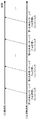
図2は、レイヤーマッピング部204およびリソースエレメントマッピング部206がマッピングするデータ信号復調用参照信号、伝送路状況測定用参照信号、情報データ信号または制御情報信号の一例を示す図である。図2はアンテナポート数が4、レイヤー数が2のときに、それぞれの信号をマッピングした場合を示している。また、周波数方向に12のサブキャリアと、時間方向に14のOFDMシンボルで構成される1つのリソースブロックを表している。1つのOFDMシンボルのうち、それぞれのサブキャリアをリソースエレメントとも呼ぶ。それぞれのサブフレームのうち、時間方向に前後の7つのOFDMシンボルをそれぞれスロットとも呼ぶ。
FIG. 2 is a diagram illustrating an example of a data signal demodulation reference signal, a transmission path condition measurement reference signal, an information data signal, or a control information signal mapped by the
図中の白色以外のリソースエレメントのうち、レイヤー番号0〜1のデータ信号復調用参照信号をそれぞれD0〜D1、アンテナポート#0〜#3の伝送路状況測定用参照信号をそれぞれC0〜C3と表わしている。また、それぞれのレイヤーおよびアンテナポートにマッピングした参照信号のリソースエレメントでは、それ以外のレイヤーおよびアンテナポートにおけるリソースエレメントに何も信号を割り当てず、ゼロ(ヌル)とすることでレイヤーおよびアンテナポート間を直交させている。なお、レイヤーおよびアンテナポート間を直交させる他の方法として、疑似雑音系列を用いた符号分割多重を適用することもできる。 Of the resource elements other than white in the figure, the data signal demodulation reference signals of layer numbers 0 to 1 are D0 to D1, respectively, and the transmission path condition measurement reference signals of antenna ports # 0 to # 3 are C0 to C3, respectively. It represents. Also, in the reference signal resource elements mapped to the respective layers and antenna ports, no signal is assigned to the resource elements in the other layers and antenna ports, and zero (null) is set between the layers and antenna ports. It is orthogonal. As another method for orthogonalizing layers and antenna ports, code division multiplexing using a pseudo-noise sequence can be applied.
なお、リソースブロックのOFDMシンボル数を変えることもできる。例えば、長いガードインターバル長を付加する場合は1つのスロットのOFDMシンボル数を6とすることができる。さらに、図中の参照信号をマッピングしたリソースエレメント以外のリソースエレメントに、情報データ信号または制御情報信号をマッピングする。なお、この例では、情報データ信号または制御情報信号のレイヤー数は最大2とすることができ、例えば、情報データ信号のレイヤー数を2、制御情報信号のレイヤー数を1とすることができる。 Note that the number of OFDM symbols in the resource block can be changed. For example, when a long guard interval length is added, the number of OFDM symbols in one slot can be six. Further, the information data signal or the control information signal is mapped to resource elements other than the resource element to which the reference signal in the figure is mapped. In this example, the maximum number of information data signal or control information signal layers can be two. For example, the number of information data signal layers can be two and the number of control information signal layers can be one.
ここで、リソースブロックは、通信システムが用いる周波数帯域幅(システム帯域幅)に応じて、その数を変えることができる。例えば、6〜110個のリソースブロックを用いることができ、さらに、周波数アグリゲーションにより、全システム帯域幅を110個以上にすることも可能である。通常コンポーネントキャリアは100物理リソースブロックで構成し、コンポーネントキャリア間にガードバンドをはさんで、5個のコンポーネントキャリアで、全システム帯域幅を500物理リソースブロックにすることができる。これを、帯域幅で表現すると、例えば、コンポーネントキャリアは20MHzで構成し、コンポーネントキャリア間にガードバンドをはさんで、5個のコンポーネントキャリアで、全システム帯域幅を100MHzにすることができる。なお、コンポーネントキャリア間にさらにサブキャリアを配置することもできる。 Here, the number of resource blocks can be changed according to the frequency bandwidth (system bandwidth) used by the communication system. For example, 6 to 110 resource blocks can be used, and the total system bandwidth can be increased to 110 or more by frequency aggregation. Usually, the component carrier is composed of 100 physical resource blocks, and the total system bandwidth can be made 500 physical resource blocks with 5 component carriers with a guard band between the component carriers. When this is expressed in terms of bandwidth, for example, the component carrier is composed of 20 MHz, and the total system bandwidth can be set to 100 MHz with five component carriers with the guard band between the component carriers. Note that subcarriers can be further arranged between the component carriers.
OFDM信号生成部207は、リソースエレメントマッピング部が出力した周波数領域の信号を、逆高速フーリエ変換(IFFT (Inverse Fast Fourier Transform))などにより周波数時間変換処理を行ない、時間領域の信号に変換する。さらに、それぞれのOFDMシンボルの一部を巡回的に拡張することでガードインターバル(サイクリックプレフィックス)を付加する。送信アンテナ208は、OFDM信号生成部が出力した信号を、ベースバンドから無線周波数への変換処理などをした後、送信する。 The OFDM signal generation unit 207 performs frequency time conversion processing on the frequency domain signal output from the resource element mapping unit by inverse fast Fourier transform (IFFT) or the like, and converts the signal into a time domain signal. Furthermore, a guard interval (cyclic prefix) is added by cyclically extending a part of each OFDM symbol. The transmission antenna 208 transmits the signal output from the OFDM signal generation unit after performing conversion processing from baseband to radio frequency.
図3は、本発明の移動端末300の構成を示す概略ブロック図である。図3において、移動端末300は、受信アンテナ301、OFDM信号復調部302、リソースエレメントデマッピング部303、フィルタ部304、レイヤーデマッピング部305、復調部306、デスクランブル部307、復号部308、伝送路推定部309、フィードバック情報生成部310(伝送路状況測定部)、送信信号生成部311、送信アンテナ312を備えている。移動端末300は少なくとも1つの受信アンテナ数の受信アンテナ301を備えており、受信アンテナ301は、基地局200が送信し、伝送路(伝搬路、チャネル)を通った信号を受信し、無線周波数からベースバンド信号への変換処理などを行なう。OFDM信号復調部302は、付加したガードインターバルを除去し、高速フーリエ変換(FFT (Fast Fourier Transform))などにより時間周波数変換処理を行ない、周波数領域の信号に変換する。
FIG. 3 is a schematic block diagram showing the configuration of the mobile terminal 300 of the present invention. In FIG. 3, a mobile terminal 300 includes a reception antenna 301, an OFDM signal demodulation unit 302, a resource element demapping unit 303, a
このとき、第k番目のサブキャリアにおける受信信号は以下のように表わされる。 At this time, the received signal in the kth subcarrier is expressed as follows.
![]()
![]()
![]()
![]()

![]()
![]()
伝送路推定部309では、入力されたデータ信号復調用参照信号に基づいて、各受信アンテナ301の各レイヤーに対する、それぞれのリソースエレメントにおける振幅と位相の変動(周波数応答、伝達関数)を推定(伝送路推定)し、伝送路推定値を求める。なお、データ信号復調用参照信号がマッピングされていないリソースエレメントは、データ信号復調用参照信号がマッピングされたリソースエレメントに基づいて、周波数方向および時間方向に補間し、伝送路推定を行なう。その補間方法としては、線形補間、放物線補間、多項式補間、ラグランジュ補間、スプライン補間、FFT補間、最小平均二乗誤差(MMSE (Minimum Mean Square Error))補間などの様々な方法を用いることができる。
The transmission
フィルタ部304では、リソースエレメントデマッピング部303が出力した受信アンテナ301毎のデータ信号に対して、伝送路推定部309が出力した伝送路推定値を用いて、伝搬路補償を行ない、送信信号S(k)を検出する。その検出方法としては、ZF (Zero Forcing)基準やMMSE基準の方法などを用いることができる。たとえば、ZF基準またはMMSE基準の検出に用いる重み係数をそれぞれMZFまたはMMMSEとすると、以下の重み係数を用いることができる。
The
![]()
![]()
![]()
![]()
図4は、本発明のフィードバック情報生成部310の構成を示す概略ブロック図である。図4において、フィードバック情報生成部310は、伝送路状況推定値算出部3101、グルーピング部3102を備えている。フィードバック情報を生成する方法として、受信した伝送路状況測定用参照信号を用いて、それぞれの送信アンテナポートに対するそれぞれの受信アンテナポートの周波数応答、受信信号電力対干渉・雑音電力比(SINR (Signal to Interference plus Noise power Ratio))、受信信号電力対干渉電力比(SIR (Signal to Interference power Ratio))、受信信号電力対雑音電力比(SNR (Signal to Noise power Ratio))、パスロスなどを測定し、それらを用いて生成することができる。
FIG. 4 is a schematic block diagram showing the configuration of the feedback
また、フィードバック情報を生成する単位として、周波数方向(例えば、サブキャリア毎、リソースエレメント毎、リソースブロック毎、複数のリソースブロックで構成されるサブバンド毎など)、時間方向(例えば、OFDMシンボル毎、サブフレーム毎、スロット毎、無線フレーム毎など)、空間方向(例えば、アンテナポート毎、送信アンテナ毎、受信アンテナ毎など)などを用いることができ、さらにそれらを組み合わせることもできる。送信信号生成部311は、フィードバック情報生成部310が出力したフィードバック情報を基地局200に送信(フィードバック)するために、符号化処理、変調処理、送信信号生成処理などを行ない、送信信号を生成する。送信アンテナ312は、送信信号生成部311が生成したフィードバック情報を含む送信信号を上り回線を通じて、基地局200に送信する。
In addition, as a unit for generating feedback information, the frequency direction (for example, for each subcarrier, for each resource element, for each resource block, for each subband composed of a plurality of resource blocks), for the time direction (for example, for each OFDM symbol, Subframes, slots, radio frames, etc.), spatial directions (for example, antenna ports, transmission antennas, reception antennas, etc.) can be used, and these can be combined. The transmission
さらに、移動端末300におけるフィードバック情報を生成する際の詳細手順について説明する。まず、フィードバック情報として、エクスプリシットCSIを求める場合を説明する。伝送路状況推定値算出部3101において、それぞれの送信アンテナポートに対するそれぞれの受信アンテナポートにおける伝送路状況を求める。そのときの第k番目のサブキャリアにおける周波数応答は以下のように表わされる。
Furthermore, a detailed procedure for generating feedback information in the mobile terminal 300 will be described. First, a case where an explicit CSI is obtained as feedback information will be described. A transmission path condition estimated
このとき、グルーピング部3102において、エクスプリシットCSIのフィードバック情報量を削減するために、送信アンテナポートおよび受信アンテナポートの両方またはいずれか一方のアンテナポートのうち、少なくとも2つのアンテナポートの周波数応答を合成処理(グルーピング)する。ここで、合成処理とは、加算、乗算、平均演算(相加平均、相乗平均を含む)、比較演算(最大、最小、選択を含む)など様々な処理を行なうことができる。また、合成処理を行なうアンテナポートに対して重みづけを行なってもよく、例えば、伝送路状況の良好なアンテナポートの重みを大きくすることができるが、これに限るものではない。以下では、合成処理として加算を行なう場合を説明する。
At this time, in order to reduce the amount of explicit CSI feedback information in
図5は、本発明の第1の実施形態の一例として、基地局401には送信アンテナポート#0〜#3、移動端末402には受信アンテナポート#0〜#3により構成されている通信システムを示す図である。そのときの第k番目のサブキャリアにおける周波数応答は以下のように表わされる。 As an example of the first embodiment of the present invention, FIG. 5 shows a communication system in which the base station 401 includes transmission antenna ports # 0 to # 3 and the mobile terminal 402 includes reception antenna ports # 0 to # 3. FIG. The frequency response in the k-th subcarrier at that time is expressed as follows.
また、フィードバック情報として、既に説明した合成処理を行った周波数応答に基づいて、インプリシットCSIを求めることもできる。特にSINRに基づいたCQI、PMI、RIを求める手順を説明する。なお、CQIおよびPMIはそれぞれ複数種類のパターン(インデックス化)として予め設定しておき、そのパターンに最も近いものを選択することもできる。インプリシットCSIを求めるための伝送路状況推定値として、既に説明した合成処理を行った周波数応答を用いる。RIを決定する場合は、固有値分解などの手法を用いて、レイヤー数を決定する。このとき、合成処理をした後の周波数応答行列の行数と列数の少ない方をレイヤー数の最大とすることが好ましい。 Further, the implicit CSI can also be obtained as feedback information based on the frequency response that has already been subjected to the combining process. In particular, a procedure for obtaining CQI, PMI, and RI based on SINR will be described. Note that CQI and PMI can be set in advance as a plurality of types of patterns (indexing), and the pattern closest to the pattern can be selected. As the transmission path state estimation value for obtaining the implicit CSI, the frequency response that has been subjected to the combining process described above is used. When determining the RI, the number of layers is determined using a technique such as eigenvalue decomposition. At this time, it is preferable that the smaller number of layers and the number of columns of the frequency response matrix after the synthesizing process be the maximum number of layers.
PMIを決定する場合は、合成処理した後の周波数応答に基づいて、最適な受信状態となるようにプレコーディング行列を求める。ここで、最適な受信状態として、例えば受信電力が最大になる状態であったり、他の基地局や他の移動端末からの干渉電力が小さい(干渉キャンセラ等を用いた場合も含む)状態などとすることができる。なお、固有値分解などの手法を用いて求めることもできる。CQIを決定する場合は、SINRに対して所要品質を満たすCQIのルックアップテーブルを予め設定しておき、決定したRIおよびPMIを用いたときのSINRを求め、ルックアップテーブルからCQIを決定する。そのとき、移動端末402における誤り率が0.1となるようにCQIを決定することが好ましい。 When determining the PMI, a precoding matrix is obtained so as to obtain an optimum reception state based on the frequency response after the synthesis process. Here, as an optimal reception state, for example, a state where reception power is maximized, or a state where interference power from other base stations or other mobile terminals is small (including the case where an interference canceller or the like is used), etc. can do. It can also be obtained using a technique such as eigenvalue decomposition. When determining the CQI, a CQI lookup table that satisfies the required quality is set in advance for the SINR, the SINR when using the determined RI and PMI is obtained, and the CQI is determined from the lookup table. At that time, it is preferable to determine the CQI so that the error rate in the mobile terminal 402 is 0.1.
以上のように、送信アンテナポートおよび受信アンテナポートの両方またはいずれか一方のアンテナポートのうち、少なくとも2つのアンテナポートの周波数応答を合成処理した周波数応答を用いて、インプリシットCSIを求めることによって、例えば、PMIなどのルックアップテーブルの数を削減することができ、フィードバック情報量を削減させることができる。また、フィードバック情報量を同じとした場合、プレコーディング処理の精度をさらに高めることができる。 As described above, by obtaining the implicit CSI using the frequency response obtained by synthesizing the frequency responses of at least two antenna ports of the transmission antenna port and / or the reception antenna port, For example, the number of lookup tables such as PMI can be reduced, and the amount of feedback information can be reduced. Further, when the amount of feedback information is the same, the accuracy of the precoding process can be further increased.
次に、以上で説明したようなフィードバック情報を用いた、基地局401の移動端末402に対する送信データ信号の送信に関して説明する。その送信方法としては様々な方法を用いることができる。例えば、図5で示した通信システムにおいて、送信アンテナポート#0〜#3のうち、送信アンテナポート#0および#1、送信アンテナポート#2および#3をそれぞれ合成処理(グルーピング)した場合を説明する。基地局401は、その移動端末402に対して送信アンテナポート#0および#1、送信アンテナポート#2および#3のそれぞれが同じプレコーディング処理をするようなプレコーディング重みを生成し、移動端末402に対する送信データ信号にそのプレコーディング重みを乗算し、送信する。また、グルーピングした送信アンテナポート間でさらに循環遅延ダイバーシチ(CDD: Cyclic Delay Diversity)などのプレコーディング処理をすることができる。その場合は基地局401または移動端末402において、グルーピングした送信アンテナポート間でのプレコーディング処理を考慮することが好ましい。 Next, transmission of a transmission data signal to the mobile terminal 402 of the base station 401 using feedback information as described above will be described. Various methods can be used as the transmission method. For example, in the communication system shown in FIG. 5, a case where transmission antenna ports # 0 and # 1 and transmission antenna ports # 2 and # 3 among transmission antenna ports # 0 to # 3 are combined (grouped) will be described. To do. The base station 401 generates precoding weights for the mobile terminal 402 so that the transmission antenna ports # 0 and # 1 and the transmission antenna ports # 2 and # 3 perform the same precoding process. The transmission data signal for is multiplied by its precoding weight and transmitted. Further, precoding processing such as cyclic delay diversity (CDD) can be further performed between the grouped transmission antenna ports. In that case, it is preferable to consider precoding processing between grouped transmission antenna ports in the base station 401 or the mobile terminal 402.
本第1の実施形態で説明した発明を用いることにより、移動端末402から基地局401に対するエクスプリシットCSIやインプリシットCSIなどのフィードバック情報の情報量を大幅に削減することができる。また、例えばパワーアンプの観点から、基地局401における送信アンテナポートの全てから信号を出力するようなシステムにおいて、それらの一部を止めることなく、基地局401から移動端末402へのデータ送信を実現することができる。 By using the invention described in the first embodiment, the amount of feedback information such as explicit CSI and implicit CSI from the mobile terminal 402 to the base station 401 can be significantly reduced. Also, for example, from the viewpoint of a power amplifier, in a system that outputs signals from all of the transmission antenna ports in the base station 401, data transmission from the base station 401 to the mobile terminal 402 is realized without stopping some of them. can do.
なお、以上の説明では、送信アンテナポートまたは受信アンテナポートに対する合成処理について説明したが、各送信アンテナポートと各受信アンテナポート間のそれぞれの伝送路状況(伝送路状況推定値)に対する合成処理とすることと同等である。なお、以上の説明では、フィードバック情報を生成する際に、伝送路状況測定用参照信号を用いる場合を説明したが、データ信号復調用参照信号を用いて生成したフィードバック情報を送信してもよい。例えば、データ信号復調用参照信号を用いて、CQI、RI、CSIなどを生成することができる。なお、送信アンテナポートまたは受信アンテナポートのうち、それぞれ一部のアンテナポートのみを合成処理してもよいし、それぞれ全てのアンテナポートを合成処理してもよい。 In the above description, the combination process for the transmission antenna port or the reception antenna port has been described. However, the combination process for each transmission path condition (transmission path condition estimated value) between each transmission antenna port and each reception antenna port is described. Is equivalent to that. In the above description, the case where the transmission path condition measurement reference signal is used when generating the feedback information has been described. However, the feedback information generated using the data signal demodulation reference signal may be transmitted. For example, CQI, RI, CSI, etc. can be generated using a data signal demodulation reference signal. Note that only a part of the antenna ports of the transmission antenna port or the reception antenna port may be combined, or all the antenna ports may be combined.
(第2の実施形態)
以下、本発明の第2の実施形態について説明する。本第2の実施形態における通信システムは、第1の実施形態における通信システムと同様の構成を備える。そのため、以下では、第1の実施形態と異なる点について説明する。本第2の実施形態では、フィードバック情報を生成するときに、コードワードに基づいて、アンテナポートに対する合成処理を行った伝送路状況推定値(周波数応答)を用いる。例えば、同一のコードワードを出力しているアンテナポートを合成処理することができる。
(Second Embodiment)
Hereinafter, a second embodiment of the present invention will be described. The communication system according to the second embodiment has the same configuration as the communication system according to the first embodiment. Therefore, below, a different point from 1st Embodiment is demonstrated. In the second embodiment, when feedback information is generated, a channel state estimation value (frequency response) obtained by performing a combining process on an antenna port based on a code word is used. For example, the antenna port outputting the same code word can be synthesized.
図6は、本発明の第2の実施形態の一例として、基地局501には送信アンテナポート#0〜#3、移動端末502には受信アンテナポート#0〜#3により構成されている通信システムを示す図である。また、基地局501において、送信アンテナポート#0および#1はコードワード#0から、送信アンテナポート#2および#3はコードワード#1から、それぞれ出力されている。そのとき、移動端末502では、送信アンテナポート#0および#1、送信アンテナポート#2および#3をそれぞれ合成処理し、その周波数応答に基づいて、フィードバック情報を生成する。
As an example of the second embodiment of the present invention, FIG. 6 shows a communication system in which the base station 501 includes transmission antenna ports # 0 to # 3 and the mobile terminal 502 includes reception antenna ports # 0 to # 3. FIG. In base station 501, transmit antenna ports # 0 and # 1 are output from codeword # 0, and transmit antenna ports # 2 and # 3 are output from
なお、一部の送信アンテナポートのみを合成処理してもよく、例えば、コードワード#0を出力している送信アンテナポート#0および#1のみを合成処理してもよい。なお、第1の実施形態でも説明したように、予め規定された少なくとも2つの受信アンテナポートの周波数応答をさらに合成処理してもよい。 Note that only a part of the transmission antenna ports may be combined, for example, only the transmission antenna ports # 0 and # 1 outputting the codeword # 0 may be combined. As described in the first embodiment, the frequency responses of at least two reception antenna ports defined in advance may be further combined.
(第3の実施形態)
以下、本発明の第3の実施形態について説明する。本第3の実施形態における通信システムは、第1の実施形態における通信システムと同様の構成を備える。そのため、以下では、第1の実施形態と異なる点について説明する。本第3の実施形態では、フィードバック情報を生成するときに、アンテナ構成に基づいた合成処理、特にアンテナ相関に基づいてアンテナポートに対する合成処理を行った伝送路状況推定値(周波数応答)を用いる。例えば、送信アンテナのアンテナ相関が高いアンテナポートを合成処理することができる。
(Third embodiment)
Hereinafter, a third embodiment of the present invention will be described. The communication system according to the third embodiment has the same configuration as the communication system according to the first embodiment. Therefore, below, a different point from 1st Embodiment is demonstrated. In the third embodiment, when feedback information is generated, a transmission path state estimation value (frequency response) obtained by performing a combining process based on an antenna configuration, particularly a combining process for an antenna port based on antenna correlation is used. For example, an antenna port having a high antenna correlation of the transmission antenna can be combined.
図7は、本発明の第3の実施形態の一例として、基地局601には送信アンテナポート#0〜#3、移動端末602には受信アンテナポート#0〜#3により構成されている通信システムを示す図である。また、基地局601において、送信アンテナポート#0および#1、送信アンテナポート#2および#3のそれぞれのアンテナ間隔は0.5波長とアンテナ相関が高く、送信アンテナポート#1および#2のアンテナ間隔は10波長とアンテナ相関が低くなっている。そのとき、移動端末602では、送信アンテナポート#0および#1、送信アンテナポート#2および#3をそれぞれ合成処理し、その周波数応答に基づいて、フィードバック情報を生成する。
FIG. 7 shows an example of a third embodiment of the present invention, in which the base station 601 includes transmission antenna ports # 0 to # 3, and the mobile terminal 602 includes reception antenna ports # 0 to # 3. FIG. Further, in the base station 601, the antenna interval between the transmission antenna ports # 0 and # 1 and the transmission antenna ports # 2 and # 3 is 0.5 wavelength and the antenna correlation is high, and the antennas of the transmission
なお、一部の送信アンテナポートのみを合成処理してもよく、例えば、アンテナ相関の高い送信アンテナポート#0および#1のみを合成処理してもよい。なお、アンテナ相関の低いアンテナポート毎に合成処理をしてもよい。なお、第1の実施形態でも説明したように、予め規定された少なくとも2つの受信アンテナポートの周波数応答をさらに合成処理してもよい。特に、本第3の実施形態で説明したように、受信アンテナ301のアンテナ相関に基づいて、合成処理をしてもよい。 Note that only a part of the transmission antenna ports may be combined, for example, only the transmission antenna ports # 0 and # 1 having high antenna correlation may be combined. The combining process may be performed for each antenna port having a low antenna correlation. As described in the first embodiment, the frequency responses of at least two reception antenna ports defined in advance may be further combined. In particular, as described in the third embodiment, the combining process may be performed based on the antenna correlation of the receiving antenna 301.
(第4の実施形態)
以下、本発明の第4の実施形態について説明する。本第4の実施形態における通信システムは、第1の実施形態における通信システムと同様の構成を備える。そのため、以下では、第1の実施形態と異なる点について説明する。本第4の実施形態では、フィードバック情報を生成するときに、アンテナ構成に基づいた合成処理、特に交差偏波アンテナを用いたときのアンテナ偏波に基づいて、アンテナポートに対する合成処理を行った伝送路状況推定値(周波数応答)を用いる。例えば、送信アンテナ208のアンテナ偏波が同一のアンテナポートを合成処理することができる。
(Fourth embodiment)
The fourth embodiment of the present invention will be described below. The communication system according to the fourth embodiment has the same configuration as the communication system according to the first embodiment. Therefore, below, a different point from 1st Embodiment is demonstrated. In the fourth embodiment, when feedback information is generated, transmission is performed by combining processing based on an antenna configuration, particularly combining processing for an antenna port based on antenna polarization when a cross-polarized antenna is used. Use the estimated road condition (frequency response). For example, an antenna port having the same antenna polarization of the transmission antenna 208 can be combined.
図8は、本発明の第4の実施形態の一例として、基地局701には送信アンテナポート#0〜#3、移動端末702には受信アンテナポート#0〜#3により構成されている通信システムを示す図である。また、基地局701において、送信アンテナポート#0および#1、送信アンテナポート#2および#3はそれぞれ交差偏波アンテナを構成している。送信アンテナポート#0および#2は水平偏波、送信アンテナポート#1および#3は垂直偏波とする。そのとき、移動端末702では、送信アンテナポート#0および#2、送信アンテナポート#1および#3をそれぞれ合成処理し、その周波数応答に基づいて、フィードバック情報を生成する。
FIG. 8 shows an example of a fourth embodiment of the present invention, in which a base station 701 includes transmission antenna ports # 0 to # 3 and a mobile terminal 702 includes reception antenna ports # 0 to # 3. FIG. In base station 701, transmission antenna ports # 0 and # 1, and transmission antenna ports # 2 and # 3 constitute cross-polarized antennas, respectively. Transmit antenna ports # 0 and # 2 are horizontally polarized waves, and transmit
なお、一部の送信アンテナポートのみを合成処理してもよく、例えば、同一偏波の送信アンテナポート#0および#2のみを合成処理してもよい。なお、異なる偏波の送信アンテナポートをそれぞれ合成処理してもよく、特に交差偏波アンテナ毎に合成処理をしてもよい。なお、第1の実施形態でも説明したように、予め規定された少なくとも2つの受信アンテナポートの周波数応答をさらに合成処理してもよい。特に、本第4の実施形態で説明したように、受信アンテナ301の偏波に基づいて、合成処理をしてもよい。 Note that only a part of the transmission antenna ports may be combined, for example, only the transmission antenna ports # 0 and # 2 having the same polarization may be combined. Note that the transmission antenna ports having different polarizations may be combined, and in particular, the combining process may be performed for each cross-polarized antenna. As described in the first embodiment, the frequency responses of at least two reception antenna ports defined in advance may be further combined. In particular, as described in the fourth embodiment, the combining process may be performed based on the polarization of the receiving antenna 301.
(第5の実施形態)
以下、本発明の第5の実施形態について説明する。本第5の実施形態における通信システムは、第1の実施形態における通信システムと同様の構成を備える。そのため、以下では、第1の実施形態と異なる点について説明する。本第5の実施形態では、フィードバック情報を生成するときに、伝送路状況に基づいて合成処理を行なう送信アンテナポートおよび受信アンテナポートを動的に選択し、選択したアンテナポートに基づいて合成処理を行った伝送路状況推定値(周波数応答)を用いる。
(Fifth embodiment)
The fifth embodiment of the present invention will be described below. The communication system according to the fifth embodiment has the same configuration as the communication system according to the first embodiment. Therefore, below, a different point from 1st Embodiment is demonstrated. In the fifth embodiment, when generating feedback information, a transmitting antenna port and a receiving antenna port that perform combining processing are dynamically selected based on transmission path conditions, and combining processing is performed based on the selected antenna port. The transmission path condition estimate (frequency response) performed is used.
図9は、本発明の第5の実施形態の一例として、基地局801には送信アンテナポート#0〜#3、移動端末802には受信アンテナポート#0〜#3により構成されている通信システムを示す図である。そのとき、移動端末802では、伝送路状況に応じて、移動端末802で最適な受信ができるように合成処理を行なう送信アンテナポートおよび受信アンテナポートを選択する。例えば、送信アンテナポート#0および#3、送信アンテナポート#1および#2をそれぞれ合成処理し、さらに受信アンテナポート#0および#2、受信アンテナポート#1および#3をそれぞれ合成処理し、その周波数応答に基づいて、フィードバック情報を生成する。フィードバック情報として、さらに合成処理を行った送信アンテナポートおよび受信アンテナポートのポート番号も通知する。また、選択および通知するポート番号は予め複数種類のパターン(インデックス化)として規定しておくこともできる。
As an example of the fifth embodiment of the present invention, FIG. 9 shows a communication system in which a base station 801 includes transmission antenna ports # 0 to # 3 and a mobile terminal 802 includes reception antenna ports # 0 to # 3. FIG. At that time, the mobile terminal 802 selects a transmission antenna port and a reception antenna port to be combined so that the mobile terminal 802 can perform optimal reception according to the transmission path condition. For example, transmission antenna ports # 0 and # 3 and transmission
なお、送信アンテナポートまたは受信アンテナポートのうち、それぞれ一部のアンテナポートのみを合成処理してもよい。 Note that only a part of the antenna ports of the transmission antenna port or the reception antenna port may be combined.
(第6の実施形態)
以下、本発明の第6の実施形態について説明する。図10は、本発明の第6の実施形態に係る無線通信システムの概略図である。本第6の実施形態における通信システムは、図10で示すように、少なくとも2つの基地局901−1および基地局901−2、移動端末902を備えているが、それらの構成は第1の実施形態における基地局200(図1)および移動端末300(図3)とそれぞれ同様の構成を備える。そのため、以下では、第1の実施形態と異なる点について説明する。
(Sixth embodiment)
The sixth embodiment of the present invention will be described below. FIG. 10 is a schematic diagram of a radio communication system according to the sixth embodiment of the present invention. As shown in FIG. 10, the communication system according to the sixth embodiment includes at least two base stations 901-1, 901-2, and a
図10では、基地局901−1および基地局901−2が移動端末902に対して協調通信を行なっている。協調通信を行なうために、両方の基地局901を光ファイバなどの有線回線(X2インターフェース)で接続し、制御情報や送信データ信号の共有などが行なわれる。なお、リレー技術などを用いた無線回線を用いることもできる。また、基地局901−1は移動端末902に対して、基地局901−1における伝送路状況測定用参照信号および移動端末902に対する送信データ信号を送信する。基地局901−2は移動端末902に対して、基地局901−2における伝送路状況測定用参照信号および移動端末902に対する送信データ信号を送信する。それらの信号は基地局901間で協調して送信される。このような協調通信を行なうことにより、基地局901間に位置する移動端末902は同一チャネル間干渉の影響を大幅に低減させることができる。
In FIG. 10, the base station 901-1 and the base station 901-2 perform cooperative communication with the
図11は、本発明の第6の実施形態に係る無線通信システムのアンテナ数に着目した概略図である。本第6の実施形態における通信システムは、図11に示すように、協調通信を行なう基地局901−1、901−2の送信アンテナポートの数が異なる。例えば、基地局901−1が備える送信アンテナポート数は4、基地局901−2が備える送信アンテナポート数は2、移動端末902が備える受信アンテナポート数は4とする。このとき、本第6の実施形態では、フィードバック情報を生成するときに、送信アンテナポート数の少ない基地局901に基づいて、送信アンテナポート数の多い基地局901における予め規定された送信アンテナポートを合成処理した伝送路状況推定値(周波数応答)を用いる。
FIG. 11 is a schematic diagram focusing on the number of antennas of a wireless communication system according to the sixth embodiment of the present invention. As shown in FIG. 11, the communication system according to the sixth embodiment differs in the number of transmission antenna ports of base stations 901-1 and 901-2 that perform cooperative communication. For example, the number of transmission antenna ports included in the base station 901-1 is 4, the number of transmission antenna ports included in the base station 901-2 is 2, and the number of reception antenna ports included in the
図12は、本発明の第6の実施形態の一例として、基地局901−1には送信アンテナポート#1−0〜#1−3、基地局901−2には送信アンテナポート#2−0〜#2−1、移動端末902には受信アンテナポート#0〜#3により構成されている通信システムを示す図である。ここで、それぞれの送信アンテナポートから送信される伝送路状況測定用参照信号は独立しており、移動端末902において独立に伝送路状況を測定できるものとする。そのとき、移動端末902では、基地局901−1に対して、送信アンテナポート#1−0および#1−1、送信アンテナポート#1−2および#1−3をそれぞれ合成処理し、その周波数応答に基づいて、フィードバック情報を生成する。また、基地局901−2に対しては、合成処理を行なわず、それぞれの周波数応答に基づいて、フィードバック情報を生成する。なお、フィードバック情報は、それぞれの基地局901に対して送信してもよいし、少なくとも1つの基地局901(例えばサービング基地局やアンカー基地局)に送信してもよい。
FIG. 12 shows, as an example of the sixth embodiment of the present invention, base station 901-1 has transmission antenna ports # 1-0 to # 1-3 and base station 901-2 has transmission antenna ports # 2-0. ~ # 2-1, a
なお、協調通信している複数の基地局901に備えている送信アンテナポートの全ての中から、予め規定された送信アンテナポートを合成処理した周波数応答からフィードバック情報を生成してもよい。なお、第1の実施形態でも説明したように、少なくとも2つの受信アンテナポートの周波数応答をさらに合成処理してもよい。なお、送信アンテナポートまたは受信アンテナポートのうち、それぞれ一部のアンテナポートのみを合成処理してもよい。なお、本第6の実施形態における発明は、第2〜5の実施形態で説明した通信システムにも適用することができる。 Note that feedback information may be generated from a frequency response obtained by synthesizing a predetermined transmission antenna port from among all the transmission antenna ports provided in the plurality of base stations 901 performing cooperative communication. As described in the first embodiment, the frequency responses of at least two reception antenna ports may be further combined. Note that only a part of the antenna ports of the transmission antenna port or the reception antenna port may be combined. The invention in the sixth embodiment can also be applied to the communication systems described in the second to fifth embodiments.
(第7の実施形態)
以下、本発明の第7の実施形態について説明する。本第7の実施形態における通信システムは、第1の実施形態における通信システムと同様の構成を備える。そのため、以下では、第1の実施形態と異なる点について説明する。本第7の実施形態では、フィードバック情報を生成するときに、空間多重数(ランク数、レイヤー数)に基づいて、アンテナポートに対する合成処理を行った伝送路状況推定値(周波数応答)を用いる。例えば、合成処理した後の送信アンテナポートに対するフィードバックの数が、基地局1001または移動端末1002が決定した空間多重数と同じになるように、合成処理を行なうことができる。
(Seventh embodiment)
The seventh embodiment of the present invention will be described below. The communication system according to the seventh embodiment has the same configuration as the communication system according to the first embodiment. Therefore, below, a different point from 1st Embodiment is demonstrated. In the seventh embodiment, when feedback information is generated, a transmission path state estimated value (frequency response) obtained by performing a combining process on an antenna port based on the number of spatial multiplexing (number of ranks, number of layers) is used. For example, the combining process can be performed so that the number of feedbacks to the transmission antenna port after the combining process is the same as the spatial multiplexing number determined by the base station 1001 or the mobile terminal 1002.
図13は、本発明の第7の実施形態の一例として、基地局1001には送信アンテナポート#0〜#3、移動端末1002には受信アンテナポート#0〜#3により構成されている通信システムを示す図である。空間多重数が4のとき、移動端末1002では、送信アンテナポート#0〜#3を合成処理せず、それぞれの周波数応答に基づいて、フィードバック情報を生成する。空間多重数が3のとき、移動端末1002では、送信アンテナポート#0および#1を合成処理し、送信アンテナポート#2および#3を合成処理せず、それぞれの周波数応答に基づいて、フィードバック情報を生成する。空間多重数が2のとき、移動端末1002では、送信アンテナポート#0および#1、送信アンテナポート#2および#3をそれぞれ合成処理し、それぞれの周波数応答に基づいて、フィードバック情報を生成する。空間多重数が1のとき、移動端末1002では、送信アンテナポート#0〜#3を合成処理し、その周波数応答に基づいて、フィードバック情報を生成する。 FIG. 13 shows an example of a seventh embodiment of the present invention, in which the base station 1001 includes transmission antenna ports # 0 to # 3, and the mobile terminal 1002 includes reception antenna ports # 0 to # 3. FIG. When the spatial multiplexing number is 4, the mobile terminal 1002 does not perform the combining process on the transmission antenna ports # 0 to # 3, and generates feedback information based on the respective frequency responses. When the spatial multiplexing number is 3, the mobile terminal 1002 performs the combining process on the transmission antenna ports # 0 and # 1, and does not perform the combining process on the transmission antenna ports # 2 and # 3, and feedback information based on the respective frequency responses. Is generated. When the number of spatial multiplexing is 2, the mobile terminal 1002 combines transmission antenna ports # 0 and # 1 and transmission antenna ports # 2 and # 3, and generates feedback information based on the respective frequency responses. When the spatial multiplexing number is 1, the mobile terminal 1002 combines the transmission antenna ports # 0 to # 3, and generates feedback information based on the frequency response.
なお、以上の説明では、合成処理した後の送信アンテナポートに対するフィードバックの数が、基地局1001または移動端末1002が決定した空間多重数と同じになるように、合成処理を行なう場合を説明したが、空間多重数に基づいて合成処理を行なうアンテナポートを決定されていればよく、これに限るものではない。なお、第1の実施形態でも説明したように、少なくとも2つの受信アンテナポートの周波数応答をさらに合成処理してもよい。なお、本第7の実施形態における発明は、第2〜6の実施形態で説明した通信システムにも適用することができる。 In the above description, the case has been described in which the combining process is performed so that the number of feedbacks to the transmission antenna port after the combining process is the same as the spatial multiplexing number determined by the base station 1001 or the mobile terminal 1002. As long as the antenna port for performing the combining process is determined based on the spatial multiplexing number, the present invention is not limited to this. As described in the first embodiment, the frequency responses of at least two reception antenna ports may be further combined. The invention in the seventh embodiment can also be applied to the communication systems described in the second to sixth embodiments.
(第8の実施形態)
以下、本発明の第8の実施形態について説明する。本第8の実施形態における通信システムは、第1の実施形態における通信システムと同様の構成を備える。そのため、以下では、第1の実施形態と異なる点について説明する。本第8の実施形態では、フィードバック情報を生成するときに、予め規定されたアンテナポートに対する合成処理を行った伝送路状況推定値(周波数応答)を用いるが、合成処理を行なうアンテナポートのパターン(コードブック)を複数種類規定しておき、フィードバックするタイミングによって切り替える(選択する)。
(Eighth embodiment)
The eighth embodiment of the present invention will be described below. The communication system according to the eighth embodiment has the same configuration as the communication system according to the first embodiment. Therefore, below, a different point from 1st Embodiment is demonstrated. In the eighth embodiment, when feedback information is generated, a transmission path state estimated value (frequency response) obtained by performing a combining process on a predetermined antenna port is used. A plurality of types of codebooks are defined and switched (selected) according to the feedback timing.
図14は、本発明の第8の実施形態の一例を示しており、N種類の合成処理を行なうパターンを予め規定しておき、移動端末1102は基地局1101に対して、N種類の合成パターンのいずれかにより合成処理を行ない、フィードバックする様子を示す図である。例えば、図5で示したように、基地局1101には送信アンテナポート#0〜#3、移動端末1102には受信アンテナポート#0〜#3により構成されている通信システムを考える。また、合成パターンは1〜3の3種類とする。第1の合成パターンでは、移動端末1102において、送信アンテナポート#0および#1、送信アンテナポート#2および#3をそれぞれ合成処理し、それぞれの周波数応答に基づいて、フィードバック情報を生成する。第2の合成パターンでは、移動端末1102において、送信アンテナポート#0および#2、送信アンテナポート#1および#3をそれぞれ合成処理し、それぞれの周波数応答に基づいて、フィードバック情報を生成する。第3の合成パターンでは、移動端末1102において、送信アンテナポート#0および#3、送信アンテナポート#1および#2をそれぞれ合成処理し、それぞれの周波数応答に基づいて、フィードバック情報を生成する。
FIG. 14 shows an example of the eighth embodiment of the present invention, in which patterns for performing N types of combining processes are defined in advance, and the mobile terminal 1102 transmits N types of combined patterns to the base station 1101. It is a figure which shows a mode that a synthesizing process is performed by either of these and it feeds back. For example, as illustrated in FIG. 5, consider a communication system in which the base station 1101 includes transmission antenna ports # 0 to # 3 and the mobile terminal 1102 includes reception antenna ports # 0 to # 3. Also, there are three types of
なお、合成パターンとして、受信アンテナポートに対して規定することができ、送信アンテナポートおよび受信アンテナポートの両方に対して規定することができる。移動端末1102では、これらの合成パターンのいずれかをフィードバックするタイミングによって切り替えて用いる。このとき、用いる合成パターンは、フィードバック回数などによって、予め規定しておくことができる。なお、用いる合成パターンは、基地局が指示してもよい。また、移動端末1102が伝送路状況などに基づいて選択してもよく、用いた合成パターンを示す情報をさらにフィードバックすることが好ましい。これにより、動的に合成処理を行なうことができ、良好な特性が実現できる。なお、用いる合成パターンは、フィードバックする(またはフィードバックを指示された)時間方向に対するパラメータ(サブフレーム番号、スロット番号、無線フレーム番号など)に基づいて規定することができる。これにより、用いる合成パターンに関する情報を通知またはフィードバックする必要がなくなり、その情報に関するオーバーヘッドを削減できる。 In addition, it can prescribe | regulate with respect to a receiving antenna port as a synthetic | combination pattern, and can prescribe | regulate with respect to both a transmitting antenna port and a receiving antenna port. The mobile terminal 1102 uses one of these composite patterns by switching according to the feedback timing. At this time, the synthesis pattern to be used can be defined in advance by the number of feedbacks. Note that the base station may instruct the synthesis pattern to be used. Further, the mobile terminal 1102 may select based on a transmission path condition or the like, and it is preferable to further feed back information indicating the combined pattern used. As a result, the composition process can be performed dynamically and good characteristics can be realized. The synthesis pattern to be used can be defined based on parameters (subframe number, slot number, radio frame number, etc.) in the time direction to be fed back (or instructed to feed back). This eliminates the need for notifying or feeding back information related to the composite pattern to be used, and reduces the overhead related to that information.
なお、以上の説明では、合成パターンの切り替えとして、フィードバックするタイミング(時間方向に対するパラメータ)に基づいていたが、これに限るものではない。例えば、周波数方向に対するパラメータ(サブキャリア、リソースブロック、サブバンド、コンポーネントキャリアなどを含む)に基づいて切り替えてもよい。また、基地局1101に対するパラメータにより切り替えてもよく、例えば、隣接する基地局1101間で切り替えてもよいし、基地局1101の構成によって切り替えてもよいし、協調通信を行なっている基地局1101間で切り替えてもよい。また、移動端末1102に対するパラメータにより切り替えてもよい。また、それらを組み合わせてもよい。なお、本第8の実施形態における発明は、第2〜7の実施形態で説明した通信システムにも適用することができる。 In the above description, the combination pattern switching is based on the feedback timing (parameter in the time direction), but is not limited thereto. For example, you may switch based on the parameter (a subcarrier, a resource block, a subband, a component carrier, etc.) with respect to a frequency direction. Also, switching may be performed according to parameters for the base station 1101, for example, switching may be performed between adjacent base stations 1101, switching may be performed depending on the configuration of the base station 1101, and between base stations 1101 performing cooperative communication. It may be switched with. Further, switching may be performed according to parameters for the mobile terminal 1102. Moreover, you may combine them. The invention in the eighth embodiment can be applied to the communication systems described in the second to seventh embodiments.
100、200、401、501、601、701、801、901−1、901−2、1001、1101 基地局
103 送信アンテナ
110、300、402、502、602、702、802、902、1002、1102 移動端末
111、210、301 受信アンテナ
113 フィードバック情報生成部
209 伝送路状況測定用参照信号生成部
310 フィードバック情報生成部
3102 グルーピング部
100, 200, 401, 501, 601, 701, 801, 901-1, 901-2, 1001, 1101
Claims (15)
伝搬路状況測定用参照信号に基づいてフィードバック情報を生成するフィードバック情報生成部を備え、
前記フィードバック情報生成部は、前記基地局の送信アンテナポートの間の重み付けを考慮してグルーピングをし、予め設定された複数種類のプレコーディング行列のうち前記基地局に対して推奨されるプレコーディング行列を示す情報を生成し、
前記複数種類のプレコーディング行列は、グルーピングされた前記送信アンテナポートのグループ毎に同一のプレコーディング処理を行なうものであることを特徴とする移動端末。 A mobile terminal that communicates with a base station having multiple transmit antenna ports,
A feedback information generation unit that generates feedback information based on the propagation path condition measurement reference signal,
The feedback information generation unit performs grouping in consideration of weighting between transmission antenna ports of the base station, and is a precoding matrix recommended for the base station among a plurality of types of precoding matrices set in advance. Generate information that indicates
The mobile terminal characterized in that the plurality of types of precoding matrices perform the same precoding process for each group of the grouped transmit antenna ports.
前記CQIは、グルーピングされた前記送信アンテナポートのグループ毎に同一のプレコーディング処理をするようなプレコーディング重みとなる予め設定された複数種類のプレコーディング行列のうち前記基地局に対して推奨されるプレコーディング行列を用いた時に、伝送品質が所要品質を満たすような符号化率および変調方式を示すものであることを特徴とする請求項1に記載の移動端末。 The feedback information generation unit generates CQI that is information indicating a coding rate and a modulation scheme recommended for the base station,
The CQI is recommended for the base station among a plurality of types of precoding matrices that are set in advance so that precoding weights for performing the same precoding processing for each group of the grouped transmit antenna ports are provided. The mobile terminal according to claim 1, wherein when the precoding matrix is used, the mobile terminal indicates a coding rate and a modulation scheme such that transmission quality satisfies a required quality.
前記基地局は、前記基地局および前記移動端末で互いに既知の伝送路状況測定用参照信号を生成する伝送路状況測定用参照信号生成部を備え、
前記移動端末は、伝搬路状況測定用参照信号に基づいてフィードバック情報を生成するフィードバック情報生成部を備え、
前記フィードバック情報生成部は、前記基地局の送信アンテナポートの間の重み付けを考慮してグルーピングをし、予め設定された複数種類のプレコーディング行列のうち前記基地局に対して推奨されるプレコーディング行列を示す情報を生成し、
前記複数種類のプレコーディング行列は、グルーピングされた前記送信アンテナポートのグループ毎に同一のプレコーディング処理を行なうものであることを特徴とする通信システム。 A communication system in which a mobile station and a base station having a plurality of transmission antenna ports communicate with each other,
The base station includes a transmission path condition measurement reference signal generation unit that generates a known transmission path condition measurement reference signal between the base station and the mobile terminal,
The mobile terminal includes a feedback information generation unit that generates feedback information based on a propagation path condition measurement reference signal,
The feedback information generation unit performs grouping in consideration of weighting between transmission antenna ports of the base station, and is a precoding matrix recommended for the base station among a plurality of types of precoding matrices set in advance. Generate information that indicates
The communication system characterized in that the plurality of types of precoding matrices perform the same precoding process for each group of the grouped transmit antenna ports.
前記CQIは、グルーピングされた前記送信アンテナポートのグループ毎に同一のプレコーディング処理をするようなプレコーディング重みとなる予め設定された複数種類のプレコーディング行列のうち前記基地局に対して推奨されるプレコーディング行列を用いた時に、伝送品質が所要品質を満たすような符号化率および変調方式を示すものであることを特徴とする請求項6に記載の通信システム。 The feedback information generation unit generates CQI that is information indicating a coding rate and a modulation scheme recommended for the base station,
The CQI is recommended for the base station among a plurality of types of precoding matrices that are set in advance so that precoding weights for performing the same precoding processing for each group of the grouped transmit antenna ports are provided. The communication system according to claim 6, wherein when a precoding matrix is used, the coding rate and the modulation method are shown such that the transmission quality satisfies the required quality.
前記基地局は、
前記基地局の送信アンテナポートの間の重み付けを考慮してグルーピングをし、前記移動端末で生成され、予め設定された複数種類のプレコーディング行列のうち前記基地局に対して推奨されるプレコーディング行列を示す情報を受信する受信部と、
前記推奨されるプレコーディング行列を示す情報に基づいて前記移動端末に対するプレコーディング処理を行なうプレコーディング部とを備え、
前記複数種類のプレコーディング行列は、グルーピングされた前記送信アンテナポートのグループ毎に同一のプレコーディング処理を行なうものであることを特徴とする基地局。 A base station that has multiple transmit antenna ports and communicates with a mobile terminal,
The base station
Grouping in consideration of weighting between transmitting antenna ports of the base station, and a precoding matrix recommended for the base station among a plurality of types of precoding matrices set in advance generated by the mobile terminal A receiving unit for receiving information indicating
A precoding unit that performs precoding processing for the mobile terminal based on information indicating the recommended precoding matrix;
The base station characterized in that the plurality of types of precoding matrices perform the same precoding process for each group of the grouped transmit antenna ports.
前記CQIに基づいて前記移動端末に対する変調方式を制御する変調部とを備え、
前記受信部は、前記基地局に対して推奨される符号化率および変調方式を示す情報であるCQIを受信し、
前記CQIは、グルーピングされた前記送信アンテナポートのグループ毎に同一のプレコーディング処理をするようなプレコーディング重みとなる予め設定された複数種類のプレコーディング行列のうち前記基地局に対して推奨されるプレコーディング行列を用いた時に、伝送品質が所要品質を満たすように符号化率および変調方式を制御することを特徴とする請求項8記載の基地局。 A coding unit for controlling a coding rate for the mobile terminal based on CQI;
A modulation unit for controlling a modulation scheme for the mobile terminal based on the CQI,
The receiving unit receives CQI which is information indicating a coding rate and a modulation scheme recommended for the base station,
The CQI is recommended for the base station among a plurality of types of precoding matrices that are set in advance so that precoding weights for performing the same precoding processing for each group of the grouped transmit antenna ports are provided. 9. The base station according to claim 8, wherein when the precoding matrix is used, the coding rate and the modulation scheme are controlled so that the transmission quality satisfies the required quality.
前記基地局の送信アンテナポートの間の重み付けを考慮してグルーピングをし、予め設定された複数種類のプレコーディング行列のうち前記基地局に対して推奨されるプレコーディング行列を示す情報を生成し、
前記複数種類のプレコーディング行列は、グルーピングされた前記送信アンテナポートのグループ毎に同一のプレコーディング処理を行なうものであることを特徴とする無線通信方法。 A wireless communication method performed by a mobile terminal for a base station having a plurality of transmission antenna ports,
Grouping in consideration of weighting between the transmission antenna ports of the base station, generating information indicating a precoding matrix recommended for the base station among a plurality of types of precoding matrices set in advance,
The wireless communication method according to claim 1, wherein the plurality of types of precoding matrices perform the same precoding process for each group of the grouped transmission antenna ports.
前記CQIは、グルーピングされた前記送信アンテナポートのグループ毎に同一のプレコーディング処理をするようなプレコーディング重みとなる予め設定された複数種類のプレコーディング行列のうち前記基地局に対して推奨されるプレコーディング行列を用いた時に、伝送品質が所要品質を満たすような符号化率および変調方式を示すものであることを特徴とする請求項10記載の無線通信方法。 Generating CQI which is information indicating a coding rate and a modulation scheme recommended for the base station;
The CQI is recommended for the base station among a plurality of types of precoding matrices that are set in advance so that precoding weights for performing the same precoding processing for each group of the grouped transmit antenna ports are provided. 11. The wireless communication method according to claim 10, wherein a coding rate and a modulation method are shown such that transmission quality satisfies required quality when a precoding matrix is used.
前記基地局は、前記基地局および前記移動端末で互いに既知の伝送路状況測定用参照信号を生成し、
前記移動端末は、前記伝搬路状況測定用参照信号に基づいて、前記基地局の送信アンテナポートの間の重み付けを考慮してグルーピングをし、予め設定された複数種類のプレコーディング行列のうち前記基地局に対して推奨されるプレコーディング行列を示す情報を生成し、
前記複数種類のプレコーディング行列は、グルーピングされた前記送信アンテナポートのグループ毎に同一のプレコーディング処理を行なうものであることを特徴とする無線通信方法。 A wireless communication method performed by a communication system in which a mobile station communicates with a base station having a plurality of transmission antenna ports,
The base station generates a reference signal for transmission path condition measurement known to the base station and the mobile terminal,
The mobile terminal performs grouping in consideration of weighting between transmission antenna ports of the base station based on the propagation path condition measurement reference signal, and the base station among a plurality of types of precoding matrices set in advance Generate information indicating the precoding matrix recommended for the station,
The wireless communication method according to claim 1, wherein the plurality of types of precoding matrices perform the same precoding process for each group of the grouped transmission antenna ports.
前記基地局の送信アンテナポートの間の重み付けを考慮してグルーピングをし、前記移動端末で生成され、予め設定された複数種類のプレコーディング行列のうち前記基地局に対して推奨されるプレコーディング行列を示す情報を受信し、
前記複数種類のプレコーディング行列は、前記移動端末に対して、グルーピングされた前記送信アンテナポートのグループ毎に同一のプレコーディング処理を行なうものであることを特徴とする無線通信方法。 A wireless communication method performed by a base station having a plurality of transmission antenna ports and communicating with a mobile terminal,
Grouping in consideration of weighting between transmitting antenna ports of the base station, and a precoding matrix recommended for the base station among a plurality of types of precoding matrices set in advance generated by the mobile terminal Receive information indicating
The radio communication method according to claim 1, wherein the plurality of types of precoding matrices perform the same precoding process for each group of the grouped transmission antenna ports with respect to the mobile terminal.
前記受信されたCQIに基づいて、グルーピングされた前記送信アンテナポートのグループ毎に同一のプレコーディング処理をするようなプレコーディング重みとなる予め設定された複数種類のプレコーディング行列のうち前記基地局に対して推奨されるプレコーディング行列を用いた時に、伝送品質が所要品質を満たすように前記移動端末に対する符号化率および変調方式を制御することを特徴とする請求項14記載の無線通信方法。 Receiving CQI which is information indicating a coding rate and a modulation scheme recommended for the base station;
Based on the received CQI, the base station out of a plurality of types of precoding matrices set in advance that have precoding weights for performing the same precoding process for each group of the grouped transmit antenna ports. 15. The radio communication method according to claim 14, wherein when a precoding matrix recommended for the mobile terminal is used, a coding rate and a modulation scheme for the mobile terminal are controlled so that transmission quality satisfies the required quality.
Priority Applications (8)
| Application Number | Priority Date | Filing Date | Title |
|---|---|---|---|
| JP2009230623A JP5149257B2 (en) | 2009-10-02 | 2009-10-02 | Wireless communication system, communication apparatus, and wireless communication method |
| EP10820377.9A EP2485522A4 (en) | 2009-10-02 | 2010-09-16 | Wireless communication system, communication apparatus, wireless communication method and terminal apparatus |
| MX2012003828A MX2012003828A (en) | 2009-10-02 | 2010-09-16 | Wireless communication system, communication apparatus, wireless communication method and terminal apparatus. |
| BR112012007539-0A BR112012007539B1 (en) | 2009-10-02 | 2010-09-16 | mobile terminal, communication system, base station and wireless communication methods |
| EA201270493A EA026041B1 (en) | 2009-10-02 | 2010-09-16 | Wireless communication system, communication apparatus, wireless communication method and terminal apparatus |
| CN201080043893.8A CN102577486B (en) | 2009-10-02 | 2010-09-16 | Wireless communication system, communicator, wireless communications method and terminal installation |
| PCT/JP2010/066085 WO2011040258A1 (en) | 2009-10-02 | 2010-09-16 | Wireless communication system, communication apparatus, wireless communication method and terminal apparatus |
| US13/436,330 US9681322B2 (en) | 2009-10-02 | 2012-03-30 | Wireless communication system, communication apparatus, wireless communication method and terminal apparatus |
Applications Claiming Priority (1)
| Application Number | Priority Date | Filing Date | Title |
|---|---|---|---|
| JP2009230623A JP5149257B2 (en) | 2009-10-02 | 2009-10-02 | Wireless communication system, communication apparatus, and wireless communication method |
Publications (3)
| Publication Number | Publication Date |
|---|---|
| JP2011082603A JP2011082603A (en) | 2011-04-21 |
| JP2011082603A5 JP2011082603A5 (en) | 2012-04-26 |
| JP5149257B2 true JP5149257B2 (en) | 2013-02-20 |
Family
ID=43826084
Family Applications (1)
| Application Number | Title | Priority Date | Filing Date |
|---|---|---|---|
| JP2009230623A Active JP5149257B2 (en) | 2009-10-02 | 2009-10-02 | Wireless communication system, communication apparatus, and wireless communication method |
Country Status (8)
| Country | Link |
|---|---|
| US (1) | US9681322B2 (en) |
| EP (1) | EP2485522A4 (en) |
| JP (1) | JP5149257B2 (en) |
| CN (1) | CN102577486B (en) |
| BR (1) | BR112012007539B1 (en) |
| EA (1) | EA026041B1 (en) |
| MX (1) | MX2012003828A (en) |
| WO (1) | WO2011040258A1 (en) |
Families Citing this family (47)
| Publication number | Priority date | Publication date | Assignee | Title |
|---|---|---|---|---|
| US8873585B2 (en) | 2006-12-19 | 2014-10-28 | Corning Optical Communications Wireless Ltd | Distributed antenna system for MIMO technologies |
| US8249540B1 (en) | 2008-08-07 | 2012-08-21 | Hypres, Inc. | Two stage radio frequency interference cancellation system and method |
| WO2011085509A1 (en) * | 2010-01-12 | 2011-07-21 | Telefonaktiebolaget L M Ericsson (Publ) | Layer-to dm rs port mapping for lte-advanced |
| KR101403150B1 (en) * | 2010-09-03 | 2014-06-03 | 후지쯔 가부시끼가이샤 | Channel state feedback for multi-cell mimo |
| JP5578617B2 (en) * | 2010-10-18 | 2014-08-27 | パナソニック インテレクチュアル プロパティ コーポレーション オブ アメリカ | Transmission method, transmission device, reception method, and reception device |
| EP2701327A4 (en) * | 2011-04-19 | 2015-03-11 | Panasonic Ip Corp America | Pre-coding method and pre-coding device |
| ES2718124T3 (en) * | 2011-06-24 | 2019-06-27 | Sun Patent Trust | Receiving device and reception procedure |
| US20150072719A1 (en) * | 2011-12-13 | 2015-03-12 | Kyocera Corporation | Mobile terminal, wireless communication system and wireless communication method |
| EP2832012A1 (en) | 2012-03-30 | 2015-02-04 | Corning Optical Communications LLC | Reducing location-dependent interference in distributed antenna systems operating in multiple-input, multiple-output (mimo) configuration, and related components, systems, and methods |
| CN108736942A (en) * | 2012-04-24 | 2018-11-02 | 株式会社Ntt都科摩 | Method for generating codebooks |
| JP6093120B2 (en) * | 2012-07-13 | 2017-03-08 | シャープ株式会社 | Mobile station apparatus, base station apparatus, and communication method |
| US9407343B2 (en) * | 2012-08-31 | 2016-08-02 | Google Technology Holdings LLC | Method and apparatus for mitigating downlink interference |
| US9768860B2 (en) * | 2012-09-07 | 2017-09-19 | Agency For Science, Technology And Research | Method and system for high bandwidth and low power body channel communication |
| KR101972945B1 (en) | 2012-09-18 | 2019-04-29 | 삼성전자 주식회사 | Method and apparatus for transmitting and receiving channel state information in wireless communication system |
| CN105308876B (en) | 2012-11-29 | 2018-06-22 | 康宁光电通信有限责任公司 | Remote unit antennas in distributing antenna system combines |
| WO2014126319A1 (en) * | 2013-02-14 | 2014-08-21 | Lg Electronics Inc. | Method and apparatus for providing antenna configuration information for massive multiple input multiple output in a wireless communication system |
| WO2014129799A1 (en) * | 2013-02-19 | 2014-08-28 | 엘지전자 주식회사 | Method for transmitting signal in multi-antenna wireless communication system and apparatus for same |
| WO2014142618A1 (en) * | 2013-03-14 | 2014-09-18 | 엘지전자 주식회사 | Method for reporting channel state information in wireless communication system and apparatus therefor |
| US9768849B2 (en) | 2013-04-04 | 2017-09-19 | Lg Electronics Inc. | Method and apparatus for reporting channel status information in wireless communication system |
| WO2014171658A1 (en) * | 2013-04-16 | 2014-10-23 | 엘지전자 주식회사 | Method and apparatus for reporting channel state information in wireless communication system |
| WO2014189129A1 (en) * | 2013-05-24 | 2014-11-27 | 日本電信電話株式会社 | Wireless communication apparatus and wireless communication method |
| US9252854B2 (en) * | 2013-06-07 | 2016-02-02 | Industrial Technology Research Institute | User equipment having channel quality indicator feedback mechanism |
| EP3014782A4 (en) * | 2013-06-25 | 2017-01-18 | LG Electronics Inc. | Method for performing beamforming based on partial antenna array in wireless communication system and apparatus therefor |
| JP6151108B2 (en) * | 2013-06-28 | 2017-06-21 | 株式会社Nttドコモ | Radio base station, user terminal, and reference signal transmission method |
| US9350444B2 (en) * | 2013-08-22 | 2016-05-24 | Broadcom Corporation | Wireless communication device with switched polarization and methods for use therewith |
| US9094154B2 (en) | 2013-09-06 | 2015-07-28 | Telefonaktiebolaget L M Ericsson (Publ) | Adaptation of transmission format |
| US20150110210A1 (en) * | 2013-10-18 | 2015-04-23 | Nokia Solutions And Networks Oy | Channel state information acquisition and feedback for full dimension multiple input multiple output |
| CN104980247B (en) * | 2014-04-04 | 2019-11-22 | 北京三星通信技术研究有限公司 | Method, base station, terminal and the system of adaptive adjustment modulation coding scheme and reference signal pattern |
| US9525472B2 (en) * | 2014-07-30 | 2016-12-20 | Corning Incorporated | Reducing location-dependent destructive interference in distributed antenna systems (DASS) operating in multiple-input, multiple-output (MIMO) configuration, and related components, systems, and methods |
| US9923736B2 (en) * | 2014-09-25 | 2018-03-20 | Lg Electronics Inc. | Method for performing channel estimation, and apparatus therefor |
| US10848206B2 (en) * | 2014-09-25 | 2020-11-24 | Lg Electronics Inc. | Reference signal transmission method in multi-antenna wireless communication system, and apparatus therefor |
| US9729267B2 (en) | 2014-12-11 | 2017-08-08 | Corning Optical Communications Wireless Ltd | Multiplexing two separate optical links with the same wavelength using asymmetric combining and splitting |
| WO2016164146A2 (en) * | 2015-03-16 | 2016-10-13 | Lockheed Martin Corporation | Apparatus and method for increased data rates in underwater communications using orbital angular momentum |
| KR20180009776A (en) * | 2015-06-23 | 2018-01-29 | 후지쯔 가부시끼가이샤 | Wireless communication control method, wireless communication system, receiving apparatus and transmitting apparatus |
| JP2019505781A (en) * | 2015-12-31 | 2019-02-28 | 華為技術有限公司Huawei Technologies Co.,Ltd. | Terminal device and positioning system |
| JP6729152B2 (en) * | 2016-08-04 | 2020-07-22 | 富士通オプティカルコンポーネンツ株式会社 | Optical transmission system and optical transmitter |
| US10257105B2 (en) | 2016-12-02 | 2019-04-09 | At&T Intellectual Property I, L.P. | Facilitation of physical layer design for 5G networks or other next generation networks |
| US10090980B2 (en) | 2017-01-08 | 2018-10-02 | At&T Intellectual Property I, L.P. | Transmission of demodulation reference signals for a 5G wireless communication network or other next generation network |
| WO2018134838A1 (en) * | 2017-01-20 | 2018-07-26 | Wisig Networks Private Limited | System and method for generating spreaded sequence with low peak-to-average power ratio (papr) waveform |
| EP3625896B1 (en) * | 2017-05-23 | 2021-09-01 | Huawei Technologies Co., Ltd. | Channel state information related feedback reporting and channel state information acquisition |
| KR102403763B1 (en) * | 2017-06-27 | 2022-05-30 | 삼성전자주식회사 | A method for configuring feedback information for channel state information feedback in wireless communication system |
| CN109787664A (en) | 2017-11-15 | 2019-05-21 | 索尼公司 | For the electronic equipment of wireless communication system, method, apparatus and storage medium |
| CN111903065B (en) * | 2018-03-23 | 2023-12-05 | 株式会社Ntt都科摩 | Base station and transmission method |
| US10778298B1 (en) | 2019-03-29 | 2020-09-15 | At&T Intellectual Property I, L.P. | Context-based precoding matrix computations for radio access network for 5G or other next generation network |
| US11139868B2 (en) * | 2019-11-12 | 2021-10-05 | Nokia Technologies Oy | Propagation link selection in telecommunication systems |
| WO2021164033A1 (en) * | 2020-02-21 | 2021-08-26 | 华为技术有限公司 | Method and apparatus for predicting channel state information |
| WO2022025316A1 (en) * | 2020-07-29 | 2022-02-03 | 엘지전자 주식회사 | Method and apparatus for transmitting and receiving signal by using multiple antennas in wireless communication system |
Family Cites Families (35)
| Publication number | Priority date | Publication date | Assignee | Title |
|---|---|---|---|---|
| US6356555B1 (en) * | 1995-08-25 | 2002-03-12 | Terayon Communications Systems, Inc. | Apparatus and method for digital data transmission using orthogonal codes |
| JP4308655B2 (en) * | 2001-09-14 | 2009-08-05 | 富士通株式会社 | Mobile communication system, mobile station and base station |
| FR2863422A1 (en) * | 2003-12-04 | 2005-06-10 | France Telecom | Signal transmitting method for wireless digital communication, involves implementing source matrix and linear precoding matrix to provide precoded matrix, and transmitting precoded vectors conforming to columns of precoded matrix |
| US8160121B2 (en) * | 2007-08-20 | 2012-04-17 | Rearden, Llc | System and method for distributed input-distributed output wireless communications |
| KR100876797B1 (en) * | 2004-07-13 | 2009-01-07 | 삼성전자주식회사 | Apparatus and method for beam forming in a multi-antenna system |
| WO2006035637A1 (en) | 2004-09-27 | 2006-04-06 | Sharp Kabushiki Kaisha | Radio transmission device |
| JP4884722B2 (en) * | 2005-03-31 | 2012-02-29 | 株式会社エヌ・ティ・ティ・ドコモ | Wireless communication apparatus and wireless communication method |
| EP1885071A4 (en) * | 2005-05-20 | 2015-01-28 | Fujitsu Ltd | Radio communication device, mobile terminal device, radio communication method |
| US7580445B2 (en) * | 2005-08-22 | 2009-08-25 | Nec Laboratories America, Inc. | Nonlinear precoding in code-division multiple access communication system |
| US7949318B2 (en) * | 2007-02-05 | 2011-05-24 | Nec Laboratories America, Inc. | Multi-rank beamforming precoding apparatus and method |
| JP4594361B2 (en) * | 2006-08-31 | 2010-12-08 | 三星電子株式会社 | Data transmitting / receiving apparatus and method in multi-antenna system and system supporting the same |
| US8111782B2 (en) | 2006-08-31 | 2012-02-07 | Samsung Electronics Co., Ltd. | Apparatus and method for transmitting/receiving data in a multi-antenna system, and system using the same |
| WO2008030806A2 (en) | 2006-09-06 | 2008-03-13 | Qualcomm Incorporated | Codeword permutation and reduced feedback for grouped antennas |
| CN101689962B (en) * | 2007-04-20 | 2016-03-16 | 交互数字技术公司 | For the method and apparatus of the efficient precoding information validation of MIMO communication |
| US8199840B2 (en) * | 2007-04-26 | 2012-06-12 | Telefonaktiebolaget Lm Ericsson (Publ) | Multiple-input, multiple-output communication system with reduced feedback |
| DK2145400T3 (en) * | 2007-04-30 | 2013-05-27 | Ericsson Telefon Ab L M | Method and apparatus for adapting a multi-antenna transmission |
| KR101282522B1 (en) * | 2007-06-19 | 2013-07-04 | 엘지전자 주식회사 | Method for transmitting control information in multiple antenna system |
| US8160601B2 (en) * | 2007-06-21 | 2012-04-17 | Elektrobit Wireless Communications Ltd. | Method for optimizing spatial modulation in a wireless link and network element thereto |
| US20100272034A1 (en) * | 2007-09-28 | 2010-10-28 | Panasonic Corporation | Base station device, mobile station device, communication system, channel estimation method, transmission antenna detection method, and program |
| KR100995045B1 (en) * | 2007-12-31 | 2010-11-19 | 엘지전자 주식회사 | A method for receiving a precoded signal in collaborative multiple input multiple output communication system |
| EP3169001B1 (en) * | 2008-01-14 | 2020-02-26 | Telefonaktiebolaget LM Ericsson (publ) | Open loop precoder cycling in mimo communications |
| US8811353B2 (en) * | 2008-04-22 | 2014-08-19 | Texas Instruments Incorporated | Rank and PMI in download control signaling for uplink single-user MIMO (UL SU-MIMO) |
| US8699446B2 (en) * | 2008-06-18 | 2014-04-15 | Centre Of Excellence In Wireless Technology | Precoding for multiple transmission streams in multiple antenna systems |
| EP3327982B1 (en) * | 2008-06-23 | 2019-08-07 | Sun Patent Trust | Method of arranging reference signals and wireless communication system |
| CA2729577C (en) * | 2008-07-01 | 2016-12-20 | George Joengren | Methods and apparatus using precoding matrices in a mimo telecommunications system |
| US8098750B2 (en) * | 2008-07-10 | 2012-01-17 | Infineon Technologies Ag | Method and device for transmitting a plurality of data symbols |
| US8213293B2 (en) * | 2008-08-13 | 2012-07-03 | Lg Electronics Inc. | Method for implementing transmit diversity at a wireless mobile communication system adopting SC-FDMA scheme |
| KR101505685B1 (en) * | 2008-09-26 | 2015-03-25 | 엘지전자 주식회사 | Method and device for cooperative MIMO transmission operation in multi-cell wireless network |
| EP2351246B1 (en) * | 2008-11-03 | 2017-02-22 | Telefonaktiebolaget LM Ericsson (publ) | Method for transmission of reference signals and determination of precoding matrices for multi-antenna transmission |
| KR101707680B1 (en) * | 2008-12-21 | 2017-02-17 | 엘지전자 주식회사 | Apparatus and method of transmitting information in wireless communication system |
| US8472539B2 (en) * | 2009-04-07 | 2013-06-25 | Lg Electronics Inc. | Method of transmitting power information in wireless communication system |
| US9154352B2 (en) * | 2009-04-21 | 2015-10-06 | Qualcomm Incorporated | Pre-communication for relay base stations in wireless communication |
| US8705510B2 (en) * | 2009-04-22 | 2014-04-22 | Lg Electronics Inc. | Method for transmitting feedback information and data using a precoding codebook for multicell cooperative communication in a wireless communication system |
| KR101647377B1 (en) * | 2009-05-22 | 2016-08-10 | 엘지전자 주식회사 | A method for adaptive multi-antenna transmission based on antenna transmission power in wireless communication system and apparatus thereof |
| JP5418685B2 (en) * | 2009-09-25 | 2014-02-19 | 富士通株式会社 | Method and apparatus for generating precoding matrix codebook |
-
2009
- 2009-10-02 JP JP2009230623A patent/JP5149257B2/en active Active
-
2010
- 2010-09-16 MX MX2012003828A patent/MX2012003828A/en active IP Right Grant
- 2010-09-16 BR BR112012007539-0A patent/BR112012007539B1/en active IP Right Grant
- 2010-09-16 CN CN201080043893.8A patent/CN102577486B/en active Active
- 2010-09-16 WO PCT/JP2010/066085 patent/WO2011040258A1/en active Application Filing
- 2010-09-16 EA EA201270493A patent/EA026041B1/en not_active IP Right Cessation
- 2010-09-16 EP EP10820377.9A patent/EP2485522A4/en not_active Withdrawn
-
2012
- 2012-03-30 US US13/436,330 patent/US9681322B2/en active Active
Also Published As
| Publication number | Publication date |
|---|---|
| EA201270493A1 (en) | 2012-12-28 |
| MX2012003828A (en) | 2012-05-08 |
| US9681322B2 (en) | 2017-06-13 |
| US20120213111A1 (en) | 2012-08-23 |
| WO2011040258A1 (en) | 2011-04-07 |
| BR112012007539A2 (en) | 2020-08-11 |
| CN102577486B (en) | 2015-11-25 |
| EP2485522A4 (en) | 2013-05-01 |
| EP2485522A1 (en) | 2012-08-08 |
| BR112012007539B1 (en) | 2021-05-18 |
| JP2011082603A (en) | 2011-04-21 |
| EA026041B1 (en) | 2017-02-28 |
| CN102577486A (en) | 2012-07-11 |
Similar Documents
| Publication | Publication Date | Title |
|---|---|---|
| JP5149257B2 (en) | Wireless communication system, communication apparatus, and wireless communication method | |
| US11005627B2 (en) | Apparatus and method for transmitting a reference signal in a wireless communication system | |
| EP2424137B1 (en) | Radio communication system, radio communication device, and radio communication method | |
| WO2010146975A1 (en) | Communication system, communication apparatus and communication method | |
| KR101501714B1 (en) | Apparatus and method for reducing the over-head in a mimo wireless communication system | |
| EP2424123B1 (en) | Apparatus and method for transmitting a reference signal in a wireless communication system | |
| JP5180299B2 (en) | Transmission method using delay diversity and space-frequency diversity | |
| EP2562951A1 (en) | Feedback information transmission method, mobile station device and base station device | |
| CN104662811B (en) | The method and its equipment of effective Feedback are sent in multi-aerial radio communication system | |
| WO2013024742A1 (en) | Terminal, base station, communication system, and communication method | |
| WO2011090106A1 (en) | Precoding weight generation method, mobile station device and base station device | |
| CN105519029A (en) | OFDM communication system and method and device for receiving and transmitting signals | |
| WO2011155360A1 (en) | Mobile terminal apparatus, base station apparatus, communication system, and communication method | |
| WO2010122749A1 (en) | Communication system, communication apparatus and communication method |
Legal Events
| Date | Code | Title | Description |
|---|---|---|---|
| A521 | Written amendment |
Free format text: JAPANESE INTERMEDIATE CODE: A523 Effective date: 20120313 |
|
| A621 | Written request for application examination |
Free format text: JAPANESE INTERMEDIATE CODE: A621 Effective date: 20120313 |
|
| A871 | Explanation of circumstances concerning accelerated examination |
Free format text: JAPANESE INTERMEDIATE CODE: A871 Effective date: 20120313 |
|
| A975 | Report on accelerated examination |
Free format text: JAPANESE INTERMEDIATE CODE: A971005 Effective date: 20120405 |
|
| A131 | Notification of reasons for refusal |
Free format text: JAPANESE INTERMEDIATE CODE: A131 Effective date: 20120410 |
|
| A521 | Written amendment |
Free format text: JAPANESE INTERMEDIATE CODE: A523 Effective date: 20120524 |
|
| A02 | Decision of refusal |
Free format text: JAPANESE INTERMEDIATE CODE: A02 Effective date: 20120626 |
|
| A521 | Written amendment |
Free format text: JAPANESE INTERMEDIATE CODE: A523 Effective date: 20120827 |
|
| A911 | Transfer of reconsideration by examiner before appeal (zenchi) |
Free format text: JAPANESE INTERMEDIATE CODE: A911 Effective date: 20120904 |
|
| TRDD | Decision of grant or rejection written | ||
| A01 | Written decision to grant a patent or to grant a registration (utility model) |
Free format text: JAPANESE INTERMEDIATE CODE: A01 Effective date: 20121009 |
|
| A601 | Written request for extension of time |
Free format text: JAPANESE INTERMEDIATE CODE: A601 Effective date: 20121105 |
|
| A602 | Written permission of extension of time |
Free format text: JAPANESE INTERMEDIATE CODE: A602 Effective date: 20121205 |
|
| A61 | First payment of annual fees (during grant procedure) |
Free format text: JAPANESE INTERMEDIATE CODE: A61 Effective date: 20121129 |
|
| R150 | Certificate of patent or registration of utility model |
Ref document number: 5149257 Country of ref document: JP Free format text: JAPANESE INTERMEDIATE CODE: R150 Free format text: JAPANESE INTERMEDIATE CODE: R150 |
|
| FPAY | Renewal fee payment (event date is renewal date of database) |
Free format text: PAYMENT UNTIL: 20151207 Year of fee payment: 3 |
|
| SG99 | Written request for registration of restore |
Free format text: JAPANESE INTERMEDIATE CODE: R316G99 |
|
| R350 | Written notification of registration of transfer |
Free format text: JAPANESE INTERMEDIATE CODE: R350 |