CN1054902C - Gas turbine apparatus and method of operating same - Google Patents
Gas turbine apparatus and method of operating same Download PDFInfo
- Publication number
- CN1054902C CN1054902C CN94119916A CN94119916A CN1054902C CN 1054902 C CN1054902 C CN 1054902C CN 94119916 A CN94119916 A CN 94119916A CN 94119916 A CN94119916 A CN 94119916A CN 1054902 C CN1054902 C CN 1054902C
- Authority
- CN
- China
- Prior art keywords
- gas turbine
- gas
- control
- centrifugal compressor
- fuel
- Prior art date
- Legal status (The legal status is an assumption and is not a legal conclusion. Google has not performed a legal analysis and makes no representation as to the accuracy of the status listed.)
- Expired - Fee Related
Links
Images


Classifications
-
- F—MECHANICAL ENGINEERING; LIGHTING; HEATING; WEAPONS; BLASTING
- F04—POSITIVE - DISPLACEMENT MACHINES FOR LIQUIDS; PUMPS FOR LIQUIDS OR ELASTIC FLUIDS
- F04D—NON-POSITIVE-DISPLACEMENT PUMPS
- F04D27/00—Control, e.g. regulation, of pumps, pumping installations or pumping systems specially adapted for elastic fluids
- F04D27/02—Surge control
- F04D27/0207—Surge control by bleeding, bypassing or recycling fluids
-
- F—MECHANICAL ENGINEERING; LIGHTING; HEATING; WEAPONS; BLASTING
- F02—COMBUSTION ENGINES; HOT-GAS OR COMBUSTION-PRODUCT ENGINE PLANTS
- F02C—GAS-TURBINE PLANTS; AIR INTAKES FOR JET-PROPULSION PLANTS; CONTROLLING FUEL SUPPLY IN AIR-BREATHING JET-PROPULSION PLANTS
- F02C3/00—Gas-turbine plants characterised by the use of combustion products as the working fluid
- F02C3/20—Gas-turbine plants characterised by the use of combustion products as the working fluid using a special fuel, oxidant, or dilution fluid to generate the combustion products
- F02C3/22—Gas-turbine plants characterised by the use of combustion products as the working fluid using a special fuel, oxidant, or dilution fluid to generate the combustion products the fuel or oxidant being gaseous at standard temperature and pressure
-
- F—MECHANICAL ENGINEERING; LIGHTING; HEATING; WEAPONS; BLASTING
- F02—COMBUSTION ENGINES; HOT-GAS OR COMBUSTION-PRODUCT ENGINE PLANTS
- F02C—GAS-TURBINE PLANTS; AIR INTAKES FOR JET-PROPULSION PLANTS; CONTROLLING FUEL SUPPLY IN AIR-BREATHING JET-PROPULSION PLANTS
- F02C9/00—Controlling gas-turbine plants; Controlling fuel supply in air- breathing jet-propulsion plants
- F02C9/26—Control of fuel supply
- F02C9/28—Regulating systems responsive to plant or ambient parameters, e.g. temperature, pressure, rotor speed
-
- F—MECHANICAL ENGINEERING; LIGHTING; HEATING; WEAPONS; BLASTING
- F02—COMBUSTION ENGINES; HOT-GAS OR COMBUSTION-PRODUCT ENGINE PLANTS
- F02C—GAS-TURBINE PLANTS; AIR INTAKES FOR JET-PROPULSION PLANTS; CONTROLLING FUEL SUPPLY IN AIR-BREATHING JET-PROPULSION PLANTS
- F02C9/00—Controlling gas-turbine plants; Controlling fuel supply in air- breathing jet-propulsion plants
- F02C9/48—Control of fuel supply conjointly with another control of the plant
-
- F—MECHANICAL ENGINEERING; LIGHTING; HEATING; WEAPONS; BLASTING
- F05—INDEXING SCHEMES RELATING TO ENGINES OR PUMPS IN VARIOUS SUBCLASSES OF CLASSES F01-F04
- F05D—INDEXING SCHEME FOR ASPECTS RELATING TO NON-POSITIVE-DISPLACEMENT MACHINES OR ENGINES, GAS-TURBINES OR JET-PROPULSION PLANTS
- F05D2270/00—Control
- F05D2270/01—Purpose of the control system
- F05D2270/09—Purpose of the control system to cope with emergencies
- F05D2270/091—Purpose of the control system to cope with emergencies in particular sudden load loss
-
- F—MECHANICAL ENGINEERING; LIGHTING; HEATING; WEAPONS; BLASTING
- F05—INDEXING SCHEMES RELATING TO ENGINES OR PUMPS IN VARIOUS SUBCLASSES OF CLASSES F01-F04
- F05D—INDEXING SCHEME FOR ASPECTS RELATING TO NON-POSITIVE-DISPLACEMENT MACHINES OR ENGINES, GAS-TURBINES OR JET-PROPULSION PLANTS
- F05D2270/00—Control
- F05D2270/01—Purpose of the control system
- F05D2270/10—Purpose of the control system to cope with, or avoid, compressor flow instabilities
- F05D2270/101—Compressor surge or stall
Landscapes
- Engineering & Computer Science (AREA)
- Chemical & Material Sciences (AREA)
- Combustion & Propulsion (AREA)
- Mechanical Engineering (AREA)
- General Engineering & Computer Science (AREA)
- Life Sciences & Earth Sciences (AREA)
- Sustainable Development (AREA)
- Control Of Positive-Displacement Air Blowers (AREA)
- Supercharger (AREA)
Abstract
In a gas turbine apparatus including a turbine stage and a compressor stage, when an abrupt load variation occurs in a centrifugal compressor which increases pressures of a fuel such as city gas or liquefied natural gas to feed the fuel, a gas turbine control device effects a control so that a discharge pressure of the centrifugal compressor can be kept to within a predetermined pressure range. When a fuel flow demand for the centrifugal compressor is inputted to the gas turbine control device, a signal corresponding to this fuel control signal is inputted to a bypass valve of the centrifugal compressor simultaneously when it is inputted to gas turbine fuel control valves provided in the gas turbine apparatus. When the load is abruptly varied, the degree of opening of the bypass valve of the centrifugal compressor is changed to a value determined by a prestored relation between the fuel control signal and the degree of opening of the bypass valve.
Description
Present invention relates in general to a kind of gas turbine installation, the gas turbine installation that relates to such type particularly: this device is installed in the power generating equipment, and use town gas or LNG Liquefied natural gas to act as a fuel, also relate to the method for operating this gas turbine installation.
Gas turbine installation has a kind of being called the working method of " load disconnection ", wherein occurs under the unusual situation in as the generator of load, and load is disconnected and protects thus gas turbine.In this mode, the load of gas turbine changes to 0% from 100% suddenly, and this change still utilizes so far closes suddenly that the fuel flow control valve reaches.At this moment, the rotating speed of gas turbine is controlled in certain scope by gas turbine control device.
Use town gas or LNG Liquefied natural gas to do in this class gas turbine installation of fuel, using centrifugal compressor to supply fuel in the firing chamber of gas turbine installation.Under the situation that above-mentioned load disconnects, the rotating speed moment ground of centrifugal compressor rises or its exhaust pressure rises.When this exhaust pressure surpassed the CLV ceiling limit value of a permission, then fuel such as town gas or LNG Liquefied natural gas excessively flowed into the firing chamber, so that gas turbine may be with unusual high speed rotation.In order to prevent this situation, the method for Shi Yonging is that the flow velocity of the fuel gas carried under pressure by centrifugal compressor is measured so far, and when flow velocity descends, and makes one to be located at valve in the current path (below be commonly referred to as " bypass valve ") and to open.
Simultaneously, when the flow velocity that is transferred gas descended, unexpected flow velocity fluctuation had caused that pulsation phenomenon, this pulsation strengthen the vibration of compressor in centrifugal compressor.In order to prevent this phenomenon, used the method for above-mentioned conventional, well-known, promptly gas flow rate is measured, when if this flow velocity is lower than predetermined value, flow velocity by centrifugal compressor is increased, preventing the fluctuation of centrifugal compressor, and bypass valve or outlet valve are opened, this supplies to the speed of the air-flow of gas turbine by control, makes it on a predetermined level.This method that prevents to pulse is referring to Japan's " JSME mechanical engineering manual ", the 6th revised edition (1985); The 10th volume, the 10-33 page or leaf, the 3.5th joint, this handbook is by Japanese IMECHE Instiution of Mechanical Engineers editor.
Above-mentioned traditional controlling method, promptly therein the speed that is transferred air-flow is measured, and when descending, opens this flow velocity bypass valve, the shortcoming that has is, also be in and close owing to be used for controlling the bypass valve (about 0.1 second) on moment of gas turbine fuel flow velocity, the exhaust pressure of centrifugal compressor has surpassed CLV ceiling limit value.
The disconnection of 100% load in the gas turbine working method is a kind of working method of load variations maximum.In this working method, be used to control the signal (FFD: fuel stream requirement) become 0% to moment of gas turbine fuel flow velocity from 100%, so that flow control valve is transformed into closed condition from opening state, therefore make gas turbine from 100% load transfer to zero load condition.
In the moment that this load disconnects, the fuel flow rate control valve is transformed into closed condition from opening state at about 0.1-0.2 in second.Therefore utilize and traditional control method for the centrifugal compressor of fuel gas by bypass valve, its response is too late.In this conventional method, the speed of the air-flow carried by centrifugal compressor is monitored, and when this flow velocity becomes less than a lower limit, bypass valve is opened.Consequently, the exhaust pressure of centrifugal compressor is instantaneous to be increased, and surpasses a CLV ceiling limit value with the tachometer value that causes gas turbine.
In gas turbine installation, even when load disconnected, the exhaust pressure of centrifugal compressor also needed to remain in the prespecified range.In order to satisfy this needs, two kinds of methods have been proposed, first kind is that the jar with big volume is set between centrifugal compressor and gas turbine, to reduce pressure surge, second kind is the response of accelerating the centrifugal compressor control command.
The object of the present invention is to provide a kind of gas turbine installation; therein even when load disconnects (load changes suddenly); the exhaust pressure that is used for fuel is supplied to the centrifugal compressor of firing chamber under pressure is prevented from too increasing; protected gas turbine installation thus, so improved its reliability.
Another purpose of the present invention is to provide a kind of centrifugal compressor, when load disconnects (perhaps changing suddenly), be used to open or close and prevent the curved road all of pulsing, and with open, close this bypass path and synchronously open, close current velocity controller.
Another object of the present invention is to provide a kind of method of operating the gas engine device at above-mentioned second method, wherein, the fuel stream requirement (FFD) of gas turbine is input on the bypass valve control gear of fuel gas compressors earlier, to prepare control to bypass valve, booster response thus, so that even when load disconnected, the exhaust pressure of centrifugal compressor also can remain in the prespecified range.
According to a first aspect of the invention, a kind of gas turbine installation is provided, this device comprises a gas turbine, this gas turbine comprises a compressor stage, one turbine stage and a firing chamber, and be used for combustible gas such as town gas or LNG Liquefied natural gas are supplied to the firing chamber by means of a centrifugal compressor under pressure, and this gaseous combustion is produced power, and a gas turbine control device, be used to control gas turbine; Wherein this centrifugal compressor comprises a gas flow tube, flows to the suction port of this compressor from the air outlet of centrifugal compressor by its combustible gas stream, and an opening/closing device, is used to open and closes this gas flow tube; Above-mentioned gas turbine control device comprises current velocity controller, is used to control the flow velocity of combustible gas, and signal occurrence device, is used to produce and is used for opening/cut-off signals of opening/closing from the signal synchronization of current velocity controller.
According to a second aspect of the invention, a kind of gas turbine installation is provided, this device comprises a gas turbine, this gas turbine comprises a compressor stage, a turbine stage and a firing chamber, and in combustible gas such as town gas or LNG Liquefied natural gas are supplied to the firing chamber by means of a centrifugal compressor under pressure, and with this gaseous combustion generation power, and a gas turbine control device, be used to control this gas turbine; Wherein gas turbine installation comprises the fuel flow rate control gear, be used to control the flow velocity of combustible gas, centrifugal compressor comprises a gas flow tube, flow to the suction port of this compressor from the air outlet of centrifugal compressor by its combustible gas stream, an and opening/closing device, be used to open and close described gas flow tube, wherein gas turbine control device comprises command device, be used to provide a command value, this command value be produce by gas turbine control device and be used to supply to the fuel flow rate control gear, when this command value supplies to the fuel flow rate control gear, also side by side supply to opening/closing.
According to a third aspect of the invention we, a kind of gas turbine installation is provided, this device comprises a gas turbine, this gas turbine comprises a compressor stage, one turbine stage and a firing chamber, and be used for combustible gas such as town gas or LNG Liquefied natural gas are supplied to the firing chamber by means of a centrifugal compressor under pressure, and this gaseous combustion is produced power, and a gas turbine control device, be used to control gas turbine; Wherein gas turbine control device comprises start-control device; Acceleration control unit; The speed/load control gear; The load limitations device; The exhaust gas temperature control gear; Selection device is used for selecting a minimum signal and being used to export this minimum signal in the control signal of respectively exporting of above-mentioned five control gear; And current velocity controller, the output that is used for reaction selection comes control flows to cross the fuel flow rate of airflow apparatus, inflammable gas flows to the suction port of this compressor by this airflow apparatus from the air outlet of centrifugal compression, and is used to control flow to the flow velocity of the fuel of gas turbine.
According to a forth aspect of the invention, a kind of centrifugal compressor is provided, be used for city gas or LNG Liquefied natural gas body are supplied to gas turbine under pressure, described centrifugal compressor comprises: a bypass path that prevents to pulse, and it extends between the suction port of the air outlet of described Hydrodynamic machine and this power engine; Be used to open and close the device of described bypass passageways; Be arranged on the current velocity controller of described Hydrodynamic machine air inlet side; And be used to produce the device of signal, be used for driving synchronously with one another described opening and shutoff device and described current velocity controller.
According to a fifth aspect of the invention, provide a kind of method of operating gas turbine installation, this device uses the burning rock gas or the town gas of being supplied with by centrifugal compressor that act as a fuel under pressure, and this method comprises the following steps:
Produce fuel control signal according at least one signal in the signal of exporting separately by the starting arrangement in the gas turbine control device that is located in the gas turbine installation, acceleration control unit, speed/load control gear, load limitations device and exhaust gas temperature control gear; And
To the flow velocity of the fuel that enters gas turbine installation and walk around the fuel of centrifugal compressor flow velocity, utilize gas turbine control device based on fuel control signal to control.
In the present invention, even when suffering from the unexpected load variations that produces by the disconnection of load in the gas turbine installation, selecting the signal of circuit output by minimum signal is that fuel control signal also is output on the bypass valve of centrifugal compressor, and bypass valve can be opened on time point early, and the exhaust pressure of centrifugal compressor can be limited on the scope that is lower than its CLV ceiling limit value.Consequently, gas turbine can be operated in the scope of required rotating speed, and the reliability of gas turbine installation is increased.In addition because the exhaust pressure degree of fluctuation of centrifugal compressor reduces, just can make be located between centrifugal compressor and the gas turbine the volume of exhaust tank descend.
Fig. 1 is the control flow sketch plan of a preferred embodiment of gas turbine installation of the present invention;
Fig. 2 is the control flow chart of Fig. 1 gas turbine installation major component;
Fig. 3 is the control block diagram of centrifugal compressor one example of the present invention;
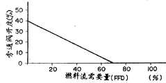
Fig. 4 is the figure of relation between explanation valve opening and the fuel stream;
Fig. 5 is the time course figure when the gas turbine load disconnects;
Fig. 6 is the oscillogram of explanation gas turbine installation one routine operating result;
Fig. 7 is the oscillogram of another operating result of gas turbine installation in the explanatory drawing 6;
Describe a preferred embodiment of gas turbine of the present invention now with reference to accompanying drawing, Fig. 1 is the control flow sketch plan of a gas turbine, and Fig. 2 is the substantial section of flow chart in the presentation graphs 1 then.Fig. 3 is the control principle figure that is used for the centrifugal compressor of fueling under pressure.
This gas turbine 113 is provided with a gas turbine control system 1.This gas turbine control system 1 is a kind of numerical control system, and it is when gas turbine starts and stops and playing the optiumum control effect when being with a loaded work piece, therefore the Gas Turbine Power generating unit is worked automatically.Control function for this purpose comprises a kind of adjustment control function and program control function.This gas turbine control system 1 also comprises a protective gear, and when the defective mode that takes place gas turbine work, this device gives the alarm and stopping gas turbine device automatically.
Adjustment control function combines with the program control function and is used for adjusting according to the working state of gas turbine the delivery volume of its fuel.In order to obtain this function, this gas turbine control system 1 comprises a start control circuit 22, acceleration limit control circuit 20, speed/load control circuit 24, load limitations control circuit 26, exhaust gas temperature control circuit 30, fuel gas control circuit 36, a fuel pressure control circuit 38 and a compressor inlet guide vane control circuit.
Load limitations control circuit 26 is used for setting the effect of playing constant output by load limitations when loaded work piece.Exhaust gas temperature control circuit 30 is used for that the exhaust gas temperature to gas turbine plays limit control when when starting and loaded work piece.When starting, these circuit 30 control fuel, so that be no more than a permitted value by the exhaust gas temperature of a thermocouple 66 detected gas turbines, and when loaded work piece, this circuit 30 limits maximum output value according to the GTE temperature of being set by a temperature setting device 28, and temperature setting device 28 is to set exhaust gas temperature according to the output value of the pressure transducer 64 of representing place, air outlet, firing chamber pressure.When temperature limitation is controlled, not temperature, but the temperature of gas turbine air outlet is measured, and a valve of being proofreaied and correct by the exhaust pressure of the compressor of gas turbine is used in this control the gas turbine inlet air mouth.
Minimum signal selects circuit 32 to select its minimum signal control signal that acts as a fuel in by above-mentioned five each output signals of control circuit.Fuel gas control circuit 36 is according to the aperture of fuel stream requirement signal (FFD) 34 definite fuel flow rate control valves of being selected circuit 32 outputs by minimum signal, so that control the fuel quantity that is mapped in the firing chamber 124 to be painted.On the other hand, fuel pressure control circuit 38 control is located at the pressure controlled valve 46 and 52 in fuel flow rate control valve 42 and 48 the place aheads respectively so that the output of pressure transducer 44 and 50 can for corresponding their predetermined values separately of gas turbine rotary speed.Compressor inlet guide vane control circuit is used for adjusting the amount that sucks (importing) air, so that the temperature of GTE is a maximum value in the limits that allows.When starting,, keep its minimum aperture by this circuit for the air impulsive motion that prevents from gas-turbine compressor, to produce.
During gas turbine installation work, these different controls will be worked.When load disconnected, the output of fuel flow rate control valve 42 and 48 based on fuel control circuits 36 was suddenly closed.
Now this is described with reference to Fig. 2 and 3.Compressor 101 supplies to town gas or liquefied natural gas the firing chamber 124 of gas turbine under pressure.Compressor 101 comprises a low pressure stage 121 and a high pressure stage 122, is provided with an interstage cooler 105 between this two-stage, and the fuel that temperature raises on low pressure stage is cooled off by this cooler, is sent to high pressure stage then.Flow measurement hole 104, one are inhaled stream valve 103 and and are inhaled flow check valve 102 and be disposed in order with this with respect to low pressure stage 121, and are connected to the upstream side of low pressure stage 121 by pipeline.On opposite side, an outlet non-return valve 106 and an exhaust tank 109 are disposed in order with this with respect to high pressure stage 122, and are connected to the downstream side of high pressure stage 122 by pipeline.In the downstream side of exhaust tank 109, the fuel pressure valve 46 of gas turbine 113 and 52 and fuel flow rate control valve 42 and 48 form by corresponding fuel conduit separately and be connected in series.These fuel pipes for example are that diameter is the pipe of 4 inches (4B).Though the preferential centrifugal compressor that adopts also can use other turbocompressor as this compressor among the present invention.In the following description, use centrifugal compressor as this compressor.
The pipe (bypass tube) of walking around centrifugal compressor 101 is connected near the point of the air outlet of the high pressure stage 122 of centrifugal compressor 101 and is connected between the air-breathing safety check 102 and the point in the middle of the flow measurement hole 104 of low pressure stage 121 (this air-flow for for simplicity hereinafter referred to as " bypass ").A bypass valve 107 and a bypass cooler 108 are located at this bypass tube midway.When the airspeed of this centrifugal compressor 101 descended, this centrifugal compressor 101 entered into pulsation zone, and causes oscillation phenomenon at last.Therefore,, the gas flow rate by centrifugal compressor is increased, and utilize and the bypass path is set makes by the portion gas of centrifugal compressor discharging and get back to suction side in order to prevent the pulsation of centrifugal compressor 101.In addition, the sensor that is used for detected pressures is arranged near the air outlet of high pressure stage 122, and the output of this sensor is sent to a pressure index regulator 140 via transmitter 146.On the other hand, the fuel flow rate that is measured by the flow measurement hole 104 that is located at low pressure stage 121 upstreams is sent to a flow velocity index regulator 144 by flow velocity transmitter 142.
In this embodiment, the relation between the aperture of the fuel of gas turbine stream requirement (FFD) and bypass valve 107 is to determine like this, promptly flows requirement (FFD) when diminishing when fuel, and bypass valve 107 is automatically opened.Can use a kind of control system of combination, wherein by the airspeed of compressor air suction as detecting by the flow measurement hole in the legacy system, and when flow velocity reached its lower limit, bypass valve 107 was opened.In the case, when being transfused to for one in fuel stream requirement (FFD) and the suction flow velocity degree control command, this bypass valve 107 is opened.In any of these methods; make centrifugal compressor pulsation protection control system 70 (it comprises pressure transmitter 146, pressure index regulator 140, flow velocity transmitter 142 and flow velocity index regulator 144) carry out work; as its result, it is 74 given to be that centrifugal compressor bypass valve aperture is instructed.
By the way, when load changes suddenly, open bypass valve with conventional method, opening of responsive valves is too late, and therefore, the discharge pressure of centrifugal compressor increases instantaneously, surpasses CLV ceiling limit value with the rotating speed that causes gas turbine.For preventing this situation, use can reach the valve of instantaneous closing (about 0.1 second), when fuel pipe uses 4 inches thick pipes, will be referred to high cost, and it is a lot of that device size is increased.Thereby gas turbine fuel stream requirement (FFD) 34 is imported into the bypass valve of centrifugal compressor, and when this fuel stream requirement (FFD) was imported into fuel gas control circuit 36, centrifugal compressor just simultaneously provided fuel under pressure.Here in each independent gas turbine installation, between the aperture of fuel stream requirement 34 and combustion gas bypass valve 107, established a predetermined relation.More specifically, for example by shown in Fig. 4, when fuel stream requirement was not less than 70%, bypass valve 107 was all opened, and when fuel stream requirement reduced, bypass valve 107 cut out gradually, and when fuel stream requirement was 0%, the aperture of bypass valve was reduced to 40%.This relation is stored in about having in the storage of gas turbine control system 1, when fuel control signal is changed, read storing value from storage, so the variation of load aspect can be by fast processing.
Various values when Fig. 5,6 and 7 is illustrated in the load disconnection over time.Fig. 5 is a plotted curve of describing them, the example of Fig. 6 and 7 expression measurement results.
In Fig. 5, when fuel stream requirement (FFD) 34 generation fuel were demandd reduction, then the aperture of gas turbine fuel flow control valve 42,48 reduced according to this requirement FFD.Because reducing requirement, fuel provides, gas turbine control system 1 just instructs the control gear of centrifugal compressor to reduce the delivery volume of the fuel of band pressure, at this moment, if only be the airspeed that reduces centrifugal compressor, then centrifugal compressor causes pulsation, and therefore the gas flow rate by centrifugal compressor must be higher than a predetermined value that does not cause pulsation.Thereby the control gear of centrifugal compressor produces the valve OPEN that is used for the centrifugal compressor bypass valve.Usually this instruction is simultaneous with the generation of fuel stream requirement (FFD), therefore compares with legacy system, and the aperture of centrifugal compressor bypass valve has reduced with respect to the time-delay of fuel stream requirement.This bypass valve open and closing operation is a kind of mechanically actuated, therefore compare with other operation, to spend the long time for the requirement that will reach.Stream flow velocity valve 103, bypass control valve (BCV) 107 and control damper 42,48 are controlled as previously discussed when inhaling, and the exhaust pressure Z-TEK of this centrifugal compressor can not surpass its CLV ceiling limit value, shown in the below, therefore can prevent pulsation as Fig. 5.Followingly a example according to the result of this operate gas turbine is described with reference to Fig. 6 and 7.
As shown in Figure 7, when the fuel flow rate control valve in 2 seconds during from 37% to 0% contract fully, the fuel gas flow velocity is from about 6100m
3/ hr is increased to about 7100m
3/ hr.On the other hand, at the fuel gas pressure at centrifugal compressor suction port place only from about 25kg/cm
2Be increased to about 27.7kg/cm
2, therefore can prevent to centrifugal compressor it is the generation of the pulsation of ill-effect.This fact that can not produce pulsation can be confirmed by the plotted curve of expression exhausting air pressure.Thereby just can obtain a kind of gas turbine installation of high reliability.In addition, when carrying out above-mentioned control, the pressure wave kinetic energy at place, centrifugal compressor air outlet is reduced, and then is provided with to be used for the volume of exhaust tank 109 of absorption pressure fluctuation and also can to reduce.
Claims (8)
1. gas turbine installation, comprising: a gas turbine, this gas turbine comprises a compressor stage, one turbine stage and a firing chamber, and firing chamber as described in being used for combustible gas supplied under pressure by means of a centrifugal compressor as town gas or LNG Liquefied natural gas, and with this gaseous combustion generation power, and a gas turbine control device, be used to control described gas turbine;
It is characterized in that wherein said centrifugal compressor comprises a gas flow tube, flow to the suction port of this compressor from the air outlet of described centrifugal compressor, and an opening/closing device, be used to open and close described gas flow tube by its combustible gas stream; And described gas turbine control device comprises current velocity controller, be used to control the flow velocity of this combustible gas, and signal occurrence device, be used to produce and be used for opening/cut-off signals of described opening/closing from the signal synchronization of described current velocity controller.
2. gas turbine installation, comprising: a gas turbine, this gas turbine comprises a compressor stage, one turbine stage and a firing chamber, and firing chamber as described in being used for combustible gas supplied under pressure by means of a centrifugal compressor as town gas or LNG Liquefied natural gas, and with this gaseous combustion generation power, and a gas turbine control device, be used to control described gas turbine;
It is characterized in that, wherein said gas turbine installation comprises the fuel flow rate control gear, be used to control the flow velocity of combustible gas, and described centrifugal compressor comprises a gas flow tube, flow to the suction port of this compressor from the air outlet of described centrifugal compressor by its combustible gas stream, an and opening/closing device, be used to open and close described gas flow tube, and wherein said gas turbine control device comprises command device, be used to provide a command value, this command value be produce by described gas turbine control device and be used to supply to described fuel flow rate control gear, when described command value supplies to described fuel flow rate control gear, also side by side supply to described opening/closing.
3. a centrifugal compressor is used for town gas or LNG Liquefied natural gas body are supplied to gas turbine under pressure, and described centrifugal compressor comprises:
A bypass path that prevents to pulse, it extends between the suction port of the air outlet of described Hydrodynamic machine and this power engine;
Be used to open and close the device of described bypass passageways;
Be arranged on the current velocity controller of described Hydrodynamic machine air inlet side; And
Be used to produce the device of signal, be used for driving synchronously with one another described opening and shutoff device and described current velocity controller.
4. gas turbine installation according to claim 1, wherein said gas turbine control device comprises storage device, stores the relation between the aperture of the signal value that produced by described signal occurrence device and described opening/closing therein in advance.
5. gas turbine installation, comprising: a gas turbine, this gas turbine comprises a compressor stage, one turbine stage and a firing chamber, and firing chamber as described in being used for combustible gas supplied under pressure by means of a centrifugal compressor as town gas or LNG Liquefied natural gas, and with this gaseous combustion generation power, and a gas turbine control device, be used to control described gas turbine;
It is characterized in that: wherein said gas turbine control device comprises start-control device; Acceleration control unit; The speed/load control gear; The load limitations device; The exhaust gas temperature control gear; Selection device is used for selecting a minimum signal and being used to export described minimum signal in the control signal of respectively exporting of above-mentioned five control gear; And current velocity controller, the output that is used to respond described selection device comes control flows to cross the fuel flow rate of airflow apparatus, combustible gas flows to the import and export of this compressor by this airflow apparatus from the air outlet of described centrifugal compressor, and is used to control flow to the flow velocity of the fuel of described gas turbine.
6. gas turbine installation according to claim 5, wherein said gas turbine control device comprises storage device, stores the relation between the flow velocity of the output signal of described selection device and the described airflow apparatus by described centrifugal compressor therein in advance.
7. method of operating gas turbine installation, this device uses LNG Liquefied natural gas that acts as a fuel or the town gas of being supplied with by centrifugal compressor under pressure, and this method comprises the following steps:
Produce fuel control signal according at least one signal in the signal of exporting separately by the starting arrangement in the gas turbine control device that is located in the described gas turbine installation, acceleration control unit, speed/load control gear, load limitations device and exhaust gas temperature control gear; And
To the flow velocity of the fuel that enters described gas turbine installation and walk around the fuel of described centrifugal compressor flow velocity, utilize described gas turbine control device to control according to described fuel control signal.
8. method according to claim 7, wherein said fuel control signal are output to the current velocity controller that streams of the fuel flow rate control gear of described gas turbine installation and described centrifugal compressor in a synchronous manner.
Applications Claiming Priority (2)
| Application Number | Priority Date | Filing Date | Title |
|---|---|---|---|
| JP33493393A JP3658415B2 (en) | 1993-12-28 | 1993-12-28 | Gas turbine equipment |
| JP334933/93 | 1993-12-28 |
Publications (2)
| Publication Number | Publication Date |
|---|---|
| CN1112190A CN1112190A (en) | 1995-11-22 |
| CN1054902C true CN1054902C (en) | 2000-07-26 |
Family
ID=18282862
Family Applications (1)
| Application Number | Title | Priority Date | Filing Date |
|---|---|---|---|
| CN94119916A Expired - Fee Related CN1054902C (en) | 1993-12-28 | 1994-12-27 | Gas turbine apparatus and method of operating same |
Country Status (5)
| Country | Link |
|---|---|
| US (1) | US5609016A (en) |
| EP (1) | EP0661426B1 (en) |
| JP (1) | JP3658415B2 (en) |
| CN (1) | CN1054902C (en) |
| DE (1) | DE69410425T2 (en) |
Cited By (2)
| Publication number | Priority date | Publication date | Assignee | Title |
|---|---|---|---|---|
| CN100476172C (en) * | 2004-11-17 | 2009-04-08 | 三菱重工业株式会社 | Compressor control unit and gas turbine power plant including the same |
| CN101126352B (en) * | 2006-08-15 | 2012-10-10 | 通用电气公司 | Methods and systems for gas turbine engine control |
Families Citing this family (33)
| Publication number | Priority date | Publication date | Assignee | Title |
|---|---|---|---|---|
| AU730820B2 (en) * | 1995-12-26 | 2001-03-15 | Kabushiki Kaisha Toshiba | Fuel supply apparatus for gas turbine and control unit for the same |
| US6035629A (en) * | 1997-08-08 | 2000-03-14 | Hamilton Sunstrand Corporation | System for controlling acceleration of a load coupled to a gas turbine engine |
| US6813875B2 (en) * | 2000-01-07 | 2004-11-09 | Honda Giken Kogyo Kabushiki Kaisha | Control system for gas-turbine engine |
| JP4317651B2 (en) * | 2000-07-21 | 2009-08-19 | 三菱重工業株式会社 | Gas turbine plant and control method of gas turbine plant |
| US6622489B1 (en) * | 2000-10-25 | 2003-09-23 | Hybrid Power Generation Systems, Llc | Integrated gas booster modulation control method |
| JP4451997B2 (en) * | 2001-02-15 | 2010-04-14 | 三菱重工業株式会社 | Speed controller for combined cycle power plant |
| GB2374904A (en) * | 2001-04-26 | 2002-10-30 | Bowman Power Systems Ltd | Controlling temperature in gas turbine apparatus during startup or shutdown |
| WO2003012271A1 (en) | 2001-08-01 | 2003-02-13 | Pipeline Controls, Inc. | Modular fuel conditioning system |
| JP3881871B2 (en) | 2001-11-13 | 2007-02-14 | 三菱重工業株式会社 | Gas turbine fuel control method and control apparatus provided therefor |
| JP3854556B2 (en) * | 2002-09-11 | 2006-12-06 | 三菱重工業株式会社 | Gas turbine plant control mechanism |
| US6892542B2 (en) * | 2002-09-13 | 2005-05-17 | General Electric Company | Gas compression system and method for microturbine application |
| US6820427B2 (en) * | 2002-12-13 | 2004-11-23 | General Electric Company | Method and apparatus for operating a turbine engine |
| JP4068546B2 (en) * | 2003-10-30 | 2008-03-26 | 株式会社日立製作所 | Gas turbine power generation facility and operation method thereof |
| ATE435366T1 (en) * | 2004-03-31 | 2009-07-15 | Alstom Technology Ltd | METHOD FOR OPERATING A HEAT ENGINE, PREFERABLY A GAS TURBINE SYSTEM |
| ATE431495T1 (en) * | 2004-03-31 | 2009-05-15 | Alstom Technology Ltd | METHOD FOR OPERATING A HEAT ENGINE, PREFERABLY A GAS TURBINE SYSTEM |
| EP1635066B1 (en) * | 2004-09-09 | 2015-06-03 | Alstom Technology Ltd | Gas supply apparatus and associated method of operation for a gas turbine |
| JP4568592B2 (en) * | 2004-12-07 | 2010-10-27 | 三菱重工業株式会社 | Fuel gas heating control device and gas turbine power generation facility provided with the fuel gas heating control device |
| US7721554B2 (en) * | 2006-02-02 | 2010-05-25 | General Electric Company | Aircraft auxiliary gas turbine engine and method for operating |
| US7712299B2 (en) * | 2006-09-05 | 2010-05-11 | Conocophillips Company | Anti-bogdown control system for turbine/compressor systems |
| US7685802B2 (en) * | 2006-12-19 | 2010-03-30 | General Electric Company | Methods and apparatus to facilitate gas turbine fuel control |
| CH700991A1 (en) | 2009-05-13 | 2010-11-15 | Alstom Technology Ltd | Method for operating a gas turbine plant with a compressor station for gaseous fuel. |
| JP4963507B2 (en) * | 2009-11-25 | 2012-06-27 | 株式会社神戸製鋼所 | Capacity control method of multistage centrifugal compressor |
| US8613189B1 (en) * | 2009-11-30 | 2013-12-24 | Florida Turbine Technologies, Inc. | Centrifugal impeller for a rocket engine having high and low pressure outlets |
| US20110302925A1 (en) * | 2010-06-14 | 2011-12-15 | Vykson Limited | Method and Apparatus for Controlling the Operation of a Gas Turbine |
| US9541005B2 (en) * | 2012-09-28 | 2017-01-10 | Pratt & Whitney Canada Corp. | Adaptive fuel manifold filling function for improved engine start |
| CN104919250B (en) * | 2012-12-21 | 2018-04-20 | 西门子公司 | The method for operating the burner of combustion gas turbine |
| CA2896461A1 (en) * | 2012-12-28 | 2014-07-03 | General Electric Company | Cryogenic fuel system and method for delivering fuel in an aircraft |
| EP3078837B1 (en) * | 2014-07-31 | 2018-02-21 | Mitsubishi Heavy Industries, Ltd. | Control device and control method |
| US10036325B2 (en) * | 2016-03-30 | 2018-07-31 | General Electric Company | Variable flow compressor of a gas turbine |
| US20180135528A1 (en) * | 2016-11-17 | 2018-05-17 | General Electric Company | Systems and methods for adaptively prefilling fuel circuits |
| CN110500295B (en) * | 2019-08-15 | 2020-07-31 | 西安陕鼓动力股份有限公司 | Automatic parallel operation method of multi-unit parallel centrifugal compressor unit |
| CN114382597B (en) * | 2021-11-10 | 2023-10-27 | 烟台杰瑞石油装备技术有限公司 | Gas turbine overspeed protection method, device, electronic equipment and readable storage medium |
| IT202200016938A1 (en) * | 2022-08-08 | 2024-02-08 | Nuovo Pignone Tecnologie Srl | Fuel Gas Booster-Gas Turbine Integration for Energy Saving and Optimized Operation |
Citations (4)
| Publication number | Priority date | Publication date | Assignee | Title |
|---|---|---|---|---|
| JPS63243427A (en) * | 1987-03-31 | 1988-10-11 | Toshiba Corp | Gas turbine fuel controller |
| EP0377292A1 (en) * | 1989-01-04 | 1990-07-11 | General Electric Company | Integrated boost compressor/gas turbine control system |
| CN1055038A (en) * | 1990-03-19 | 1991-10-02 | 株式会社日立制作所 | The method and the device of control gas turbine fuel |
| JPH1134030A (en) * | 1997-07-18 | 1999-02-09 | Ishikawajima Harima Heavy Ind Co Ltd | Method for casting high-fluidity concrete into form |
Family Cites Families (5)
| Publication number | Priority date | Publication date | Assignee | Title |
|---|---|---|---|---|
| JPS5584896A (en) * | 1978-12-22 | 1980-06-26 | Ishikawajima Harima Heavy Ind Co Ltd | Control valve operation method for turbo-compressor |
| JPS5726299A (en) * | 1980-07-25 | 1982-02-12 | Ishikawajima Harima Heavy Ind Co Ltd | Pressure control unit for compressor |
| JPS623198A (en) * | 1985-06-28 | 1987-01-09 | Hitachi Ltd | Capacity controller for turbocompressor |
| DE3810717A1 (en) * | 1988-03-30 | 1989-10-19 | Gutehoffnungshuette Man | METHOD FOR PREVENTING THE PUMPING OF A TURBO COMPRESSOR BY MEANS OF A BLOW-OFF CONTROL |
| JPH02259299A (en) * | 1989-03-31 | 1990-10-22 | Ishikawajima Harima Heavy Ind Co Ltd | Automatic load control device of centrifugal compressor |
-
1993
- 1993-12-28 JP JP33493393A patent/JP3658415B2/en not_active Expired - Fee Related
-
1994
- 1994-12-15 DE DE69410425T patent/DE69410425T2/en not_active Expired - Fee Related
- 1994-12-15 EP EP94119846A patent/EP0661426B1/en not_active Expired - Lifetime
- 1994-12-22 US US08/361,503 patent/US5609016A/en not_active Expired - Fee Related
- 1994-12-27 CN CN94119916A patent/CN1054902C/en not_active Expired - Fee Related
Patent Citations (4)
| Publication number | Priority date | Publication date | Assignee | Title |
|---|---|---|---|---|
| JPS63243427A (en) * | 1987-03-31 | 1988-10-11 | Toshiba Corp | Gas turbine fuel controller |
| EP0377292A1 (en) * | 1989-01-04 | 1990-07-11 | General Electric Company | Integrated boost compressor/gas turbine control system |
| CN1055038A (en) * | 1990-03-19 | 1991-10-02 | 株式会社日立制作所 | The method and the device of control gas turbine fuel |
| JPH1134030A (en) * | 1997-07-18 | 1999-02-09 | Ishikawajima Harima Heavy Ind Co Ltd | Method for casting high-fluidity concrete into form |
Cited By (2)
| Publication number | Priority date | Publication date | Assignee | Title |
|---|---|---|---|---|
| CN100476172C (en) * | 2004-11-17 | 2009-04-08 | 三菱重工业株式会社 | Compressor control unit and gas turbine power plant including the same |
| CN101126352B (en) * | 2006-08-15 | 2012-10-10 | 通用电气公司 | Methods and systems for gas turbine engine control |
Also Published As
| Publication number | Publication date |
|---|---|
| EP0661426B1 (en) | 1998-05-20 |
| US5609016A (en) | 1997-03-11 |
| DE69410425T2 (en) | 1998-11-05 |
| JP3658415B2 (en) | 2005-06-08 |
| JPH07189744A (en) | 1995-07-28 |
| DE69410425D1 (en) | 1998-06-25 |
| CN1112190A (en) | 1995-11-22 |
| EP0661426A1 (en) | 1995-07-05 |
Similar Documents
| Publication | Publication Date | Title |
|---|---|---|
| CN1054902C (en) | Gas turbine apparatus and method of operating same | |
| US6484490B1 (en) | Gas turbine system and method | |
| US6226974B1 (en) | Method of operation of industrial gas turbine for optimal performance | |
| US4428194A (en) | Compressor bleed air control apparatus and methods | |
| EP0059061B2 (en) | Compressor bleed air control apparatus and methods | |
| US4449360A (en) | Stall detector and surge prevention feature for a gas turbine engine | |
| US6990814B2 (en) | Engine turbocharger control management system | |
| US4625510A (en) | Stress limiter apparatus for a gas turbine engine | |
| US4437303A (en) | Fuel control system for a gas turbine engine | |
| CA1240381A (en) | Transient gas turbine engine bleed control | |
| CN1055038A (en) | The method and the device of control gas turbine fuel | |
| JPS61149531A (en) | Apparatus for confirming finish of stall/surging | |
| EP0657636B1 (en) | Control system and method for turbocharged internal combustion engines | |
| US4507915A (en) | Stall detector and surge prevention feature for a gas turbine engine | |
| EP0037786A2 (en) | Fuel control apparatus | |
| US4640091A (en) | Apparatus for improving acceleration in a multi-shaft gas turbine engine | |
| US4149371A (en) | Air supply control system | |
| US5447023A (en) | Synthesized fuel flow rate and metering valve position | |
| CA1177264A (en) | Method and apparatus for acceleration limiting a gas turbine engine | |
| EP0063999A1 (en) | Fuel control system for a gas turbine engine | |
| US4590759A (en) | Method and apparatus for improving acceleration in a multi-shaft gas turbine engine | |
| CA1087084A (en) | Flare gas limiting apparatus for coal gasification unit | |
| JP3703872B2 (en) | gas turbine | |
| US4606189A (en) | Fuel control | |
| JPH036334B2 (en) |
Legal Events
| Date | Code | Title | Description |
|---|---|---|---|
| C10 | Entry into substantive examination | ||
| SE01 | Entry into force of request for substantive examination | ||
| C10 | Entry into substantive examination | ||
| SE01 | Entry into force of request for substantive examination | ||
| C06 | Publication | ||
| PB01 | Publication | ||
| C14 | Grant of patent or utility model | ||
| GR01 | Patent grant | ||
| C19 | Lapse of patent right due to non-payment of the annual fee | ||
| CF01 | Termination of patent right due to non-payment of annual fee |