JP4068546B2 - Gas turbine power generation facility and operation method thereof - Google Patents
Gas turbine power generation facility and operation method thereof Download PDFInfo
- Publication number
- JP4068546B2 JP4068546B2 JP2003370324A JP2003370324A JP4068546B2 JP 4068546 B2 JP4068546 B2 JP 4068546B2 JP 2003370324 A JP2003370324 A JP 2003370324A JP 2003370324 A JP2003370324 A JP 2003370324A JP 4068546 B2 JP4068546 B2 JP 4068546B2
- Authority
- JP
- Japan
- Prior art keywords
- gas
- gas turbine
- fuel
- compressor
- power generation
- Prior art date
- Legal status (The legal status is an assumption and is not a legal conclusion. Google has not performed a legal analysis and makes no representation as to the accuracy of the status listed.)
- Expired - Fee Related
Links
Images


Classifications
-
- F—MECHANICAL ENGINEERING; LIGHTING; HEATING; WEAPONS; BLASTING
- F02—COMBUSTION ENGINES; HOT-GAS OR COMBUSTION-PRODUCT ENGINE PLANTS
- F02C—GAS-TURBINE PLANTS; AIR INTAKES FOR JET-PROPULSION PLANTS; CONTROLLING FUEL SUPPLY IN AIR-BREATHING JET-PROPULSION PLANTS
- F02C7/00—Features, components parts, details or accessories, not provided for in, or of interest apart form groups F02C1/00 - F02C6/00; Air intakes for jet-propulsion plants
- F02C7/22—Fuel supply systems
-
- F—MECHANICAL ENGINEERING; LIGHTING; HEATING; WEAPONS; BLASTING
- F02—COMBUSTION ENGINES; HOT-GAS OR COMBUSTION-PRODUCT ENGINE PLANTS
- F02C—GAS-TURBINE PLANTS; AIR INTAKES FOR JET-PROPULSION PLANTS; CONTROLLING FUEL SUPPLY IN AIR-BREATHING JET-PROPULSION PLANTS
- F02C3/00—Gas-turbine plants characterised by the use of combustion products as the working fluid
- F02C3/20—Gas-turbine plants characterised by the use of combustion products as the working fluid using a special fuel, oxidant, or dilution fluid to generate the combustion products
- F02C3/22—Gas-turbine plants characterised by the use of combustion products as the working fluid using a special fuel, oxidant, or dilution fluid to generate the combustion products the fuel or oxidant being gaseous at standard temperature and pressure
-
- F—MECHANICAL ENGINEERING; LIGHTING; HEATING; WEAPONS; BLASTING
- F02—COMBUSTION ENGINES; HOT-GAS OR COMBUSTION-PRODUCT ENGINE PLANTS
- F02C—GAS-TURBINE PLANTS; AIR INTAKES FOR JET-PROPULSION PLANTS; CONTROLLING FUEL SUPPLY IN AIR-BREATHING JET-PROPULSION PLANTS
- F02C6/00—Plural gas-turbine plants; Combinations of gas-turbine plants with other apparatus; Adaptations of gas- turbine plants for special use
- F02C6/04—Gas-turbine plants providing heated or pressurised working fluid for other apparatus, e.g. without mechanical power output
- F02C6/06—Gas-turbine plants providing heated or pressurised working fluid for other apparatus, e.g. without mechanical power output providing compressed gas
Description
本発明は、ガスタービン発電設備及びその運用方法に係り、特に、老朽化したガス田で採掘量および圧力が低下した天然ガスや、油田で石油採掘時に得られる圧力の低い随伴ガスなど,老朽ガス田等のガスを用いたガスタービン発電設備及びその運用方法に関する。 The present invention relates to a gas turbine power generation facility and a method for operating the same, and more particularly, aged gas such as natural gas whose amount and pressure have been reduced in an aged gas field, and an associated gas having a low pressure obtained when oil is mined in an oil field. The present invention relates to a gas turbine power generation facility using gas such as rice fields and an operation method thereof.
世界規模での環境汚染に対して、各種エンジンに対する排気ガスの規制が進められている。このような状況の中で、環境への影響が少ない燃料として天然ガスがある。 Exhaust gas regulations for various engines are being promoted against global environmental pollution. Under such circumstances, natural gas is a fuel that has little environmental impact.
天然ガスNGをガス田GFから消費地に送る方法としては、図1に示すように、ガス田において液化設備を用いて天然ガスを液化して消費地に陸上輸送もしくは海上輸送したり、パイプラインPLよりガスのまま消費地に輸送する方法がある。パイプラインには、天然ガスがパイプラインを流れるにつれ生じる圧力損失をポンプにより昇圧するためのブースターステーションBSが数箇所設置されている。ブースターステーションBSの間隔は、例えば、数10km〜数100kmである。なお、一般的なガスタービン発電設備の構成としては、例えば、特開2003−166428号公報や特開2002−327629号公報に記載のものが知られている。 As shown in FIG. 1, natural gas NG is sent from the gas field GF to the consumption area by liquefying natural gas using a liquefaction facility in the gas field and transporting it to the consumption area by land or sea. There is a method of transporting gas to PL as it is from PL. In the pipeline, several booster stations BS are installed for boosting the pressure loss generated by the natural gas as it flows through the pipeline. The interval between the booster stations BS is, for example, several tens km to several hundreds km. In addition, as a structure of general gas turbine power generation equipment, the thing of Unexamined-Japanese-Patent No. 2003-166428 and Unexamined-Japanese-Patent No. 2002-327629 is known, for example.
しかしながら、天然ガス田では採掘が進み老朽化すると、採掘量が少なくなるため、液化天然ガスにして輸送したり、パイプラインでガス輸送するためのコストの負担が増加して、利益を確保できなくなる。そこで、従来は、このような老朽ガス田からの天然ガスは消費地に送られず、有効に利用されることはないものであった。 However, if mining progresses in the natural gas field, and the amount of mining decreases, the amount of mining decreases, so the cost of transporting liquefied natural gas or transporting gas through the pipeline increases, making it impossible to secure profits. . Therefore, conventionally, the natural gas from such an old gas field has not been sent to the consuming area and has not been used effectively.
また、油田で石油採掘時に同時に随伴ガスが得られ、このガスについても従来は有効に使われることはないものであった。 Also, associated gas was obtained at the same time as oil extraction in the oil field, and this gas has not been used effectively in the past.
本発明の目的は、老朽化したガス田から得られる天然ガスや、油田から得られる随伴ガスなど,老朽ガス田等のガスを有効利用可能なガスタービン発電設備及びその運用方法を提供することにある。 An object of the present invention is to provide a gas turbine power generation facility capable of effectively using a gas from an old gas field, such as natural gas obtained from an old gas field or an accompanying gas obtained from an oil field, and an operation method thereof. is there.
(1)上記目的を達成するために、本発明は、老朽ガス田もしくは油田近傍に設置されたガスタービンを有し、老朽ガス田で発生する天然ガスもしくは油田で発生する随伴ガスを用いて前記ガスタービンにより発電し、得られた電気を消費地に供給するガスタービン発電設備であって、前記ガスタービンは圧縮機にて圧縮した空気を燃焼器に導き、燃料と混合させた後に燃焼させて、その燃焼ガスによりタービンを駆動し、さらに前記ガスタービンの回転軸から得られる動力で発電機を駆動するガスタービンであり、前記ガスタービンの回転軸から得られる動力で駆動するブースト圧縮機と、前記ガスタービンの前記圧縮機の出口もしくは途中から前記ブースト圧縮機入口に至る空気系統と、前記空気系統に設置された抽気弁と、前記ブースト圧縮機入口側であって、前記空気系統の接続位置よりも上流に設置された切り替え弁とを備え、前記天然ガスもしくは随伴ガスを燃料として前記ブースト圧縮機で昇圧し燃焼器に供給するこようにしたものである。 (1) In order to achieve the above object, the present invention has a gas turbine installed in the vicinity of an old gas field or an oil field, and uses the natural gas generated in the old gas field or the associated gas generated in the oil field. A gas turbine power generation facility that generates electricity by a gas turbine and supplies the obtained electricity to a consumer area, wherein the gas turbine guides air compressed by a compressor to a combustor, mixes it with fuel, and burns it. to drive the turbine by the combustion gas, a further gas turbine which drives a generator by the rotation axis or we obtain the power of the gas turbine, and a boost compressor driven by the power obtained from the rotation axis of the gas turbine An air system from the outlet of the compressor of the gas turbine to the boost compressor inlet, a bleed valve installed in the air system, and the booth A compressor inlet side, the a the installed switching valve upstream from the connection position of the air system will child stranded supplies the boosted combustor by the boost compressor the natural gas or associated gas as fuel It is a thing.
かかる構成により、老朽ガス田等のガスを有効利用し得るものとなる。 With this configuration, gas from an old gas field or the like can be used effectively.
かかる構成により、老朽ガス田等のガスを有効利用し得るものとなる。 With this configuration, gas from an old gas field or the like can be used effectively.
かかる方法により、老朽ガス田等のガスを有効利用し得るものとなる。 By this method, gas from an old gas field or the like can be used effectively.
本発明によれば、老朽ガス田等のガスを有効利用することができる。 According to the present invention, gas such as an old gas field can be effectively used.
以下、図2〜図5を用いて、本発明の第1の実施形態による老朽ガス田等のガスを用いたガスタービン発電設備及びその運用方法について説明する。なお、以下の説明では、老朽ガス田で採掘される天然ガスを例にして説明する。 Hereinafter, the gas turbine power generation facility using gas such as an aged gas field and the operation method thereof according to the first embodiment of the present invention will be described with reference to FIGS. In the following description, natural gas mined in an old gas field will be described as an example.
最初に、図2を用いて、本実施形態によるガスタービン発電設備を用いた天然ガスの有効利用法の概念について説明する。
図2は、本発明の第1の実施形態によるガスタービン発電設備を用いた天然ガスの有効利用法の概念図である。
Initially, the concept of the effective utilization method of the natural gas using the gas turbine power generation equipment by this embodiment is demonstrated using FIG.
FIG. 2 is a conceptual diagram of an effective utilization method of natural gas using the gas turbine power generation facility according to the first embodiment of the present invention.
本発明の第1の特徴とする点は、天然ガスの老朽ガス田GFの近傍にガスタービン発電設備10を配置したことにある。老朽ガス田の天然ガスは、採掘量が少なくなるだけでなく、採掘されたときの天然ガスの圧力も低下する。そのような少量,低圧の天然ガスを有効利用するために、老朽ガス田近傍にガスタービン発電設備10を設置する。ガスタービン発電設備10は、設備コストが低く、高効率で、天然ガスを燃料にすることができるため、天然ガスを有効利用するために用いる発電設備として好適である。
The first characteristic feature of the present invention resides in that the gas turbine
ガスタービン発電設備10は、ガスタービン圧縮機1と、燃焼器2と、タービン3と、変速機4と、発電機5とを備えている。本発明では、天然ガスのガス田GFの近傍にガスタービン発電設備10を配置して、ガス田GFから得られる天然ガスNGを燃料ガス供給系統7を介して、タービン3を駆動するための燃料として発電する。発電された電力は、ケーブルCを介して、消費地に供給される。なお、発生した電気の消費は、老朽ガス田設備以外の場所に限らず、需要があれば老朽ガス田設備内でもよいものである。
The gas turbine
ここで、ガスタービン発電設備10は、老朽ガス田GFの直上に配置するのが理想的であるが、立地条件等により直上に配置するのが難しい場合もある。その際は、パイプを介して、ガスタービン発電設備10まで供給する必要がある。しかしながら、ガス田GFからガスタービン発電設備10までの距離が長くなると、パイプの全長が長くなり、パイプの配設コストが上昇するとともに、パイプ内での圧力損失も大きくなる。そこで、老朽ガス田GFの近傍とは、老朽ガス田からの天然ガスをガスタービン発電設備10に供給してガスタービンを運転できる距離である。実質的には、老朽ガス田GFの近傍とは、ガス田GFから約20km以内で10km程度の距離までである。
Here, it is ideal to arrange the gas turbine
次に、本発明の第2の特徴としては、ブースト圧縮機6を備えるとともに、このブースト圧縮機6を、ガスタービン発電設備10のタービン3の回転軸から得られる動力により駆動することにある。老朽ガス田から得られる天然ガスの圧力は、低圧である。一方、ガスタービン3の燃焼器2に供給される燃料の圧力は、ガスタービン圧縮機1で昇圧され燃焼器2に供給される燃焼空気の圧力より高くなければならない。そこで、本実施形態では、この低圧のガスを利用するため、ブースト圧縮機6を備えている。そして、ブースト圧縮機6は、タービン3の回転軸から得られる動力を変速機4により変速して、この動力により駆動するようにして、新たなモータ等の駆動源を不要としている。ブースト圧縮機6により昇圧された天然ガスは、逆止弁8及び燃料流量調節弁9を介して、燃焼器2に供給される。
Next, as a second feature of the present invention, the
次に、図3を用いて、本実施形態によるガスタービン発電設備の構成について説明する。
図3は、本発明の第1の実施形態によるガスタービン発電設備の系統図である。なお、図2と同一符号は、同一部分を示している。
Next, the configuration of the gas turbine power generation facility according to the present embodiment will be described with reference to FIG.
FIG. 3 is a system diagram of the gas turbine power generation facility according to the first embodiment of the present invention. The same reference numerals as those in FIG. 2 indicate the same parts.
ガスタービンへ供給された燃料ガスは、燃焼器2にてガスタービン圧縮機1からの燃焼空気により燃焼し、その燃焼ガスによりタービン3を駆動する。タービンで得られた動力は、変速機4を介して発電機5を駆動して発電する。老朽したガス田では発掘される天然ガスの圧力が低いために、そのままガスタービン燃料として使用することができないため、昇圧する必要がある。そこで、発電機5の変速機4からの軸力で燃料ブースト圧縮機6を駆動し、燃料を昇圧することにより、逆止弁8及び燃料流量調節弁9を介して、燃焼器2に供給する。
The fuel gas supplied to the gas turbine is burned by the combustion air from the gas turbine compressor 1 in the combustor 2, and the turbine 3 is driven by the combustion gas. The power obtained by the turbine generates power by driving the generator 5 via the transmission 4. In an old gas field, the pressure of the natural gas excavated is low and cannot be used as it is as a gas turbine fuel. Therefore, it is necessary to increase the pressure. Therefore, the
ここで、一般的なガスタービンの圧力について説明する。通常、老朽ガス田で発生する天然ガスの圧力P1は、例えば、10ata未満である。採掘量が低下し、しかも、低圧となると、従来のように、パイプラインで消費地に供給することができず、また、パイプライン設備を維持し、経済的に成立するだけの利益を確保することが難しくなる。また、液化して輸送する方法でも、液化設備や輸送設備を維持し、経済的に成立するだけの利益を確保することが難しくなる。 Here, the pressure of a general gas turbine will be described. Usually, the pressure P1 of natural gas generated in an old gas field is, for example, less than 10 ata. If the mining volume is reduced and the pressure is low, it will not be possible to supply to the consumption area via the pipeline as in the past, and the pipeline facilities will be maintained to ensure profits that will be economically established. It becomes difficult. Further, even in the method of transporting by liquefaction, it is difficult to maintain the liquefaction facility and the transport facility and secure a profit that is economically established.
一方、ガスタービンの圧縮機1の圧力比は通常10〜20であるため、燃焼用空気の圧力P2は、10〜20ataとなる。このままでは圧力バランス上、天然ガスをガスタービン燃焼器2に供給できない。そこで、ブースト圧縮機6は、圧縮機1の軸端から発電機5を駆動するための変速機4を介して駆動し、老朽ガス田からの天然ガスの圧力をガスタービン用燃焼器の燃料として必要とする圧力P2,例えば、20〜30ataに昇圧して燃焼器2に供給する。燃焼用空気圧力P2(10〜20ata)に対して、燃料となる天然ガスの圧力P3が20〜30ataあるのは、燃焼器2の内部の圧力損失を考慮しているからである。このようにガスタービン軸から変速機4を介して駆動力をブースト圧縮機6に伝えることにより、ブースト圧縮機6をガスタービンの一部とすることができ、設備をコンパクトにできる。また、ブースト圧縮機6をガスタービンの軸力を用いない別置きのモータ等(図示せず)で駆動する場合に比べて、ガスタービンの軸力で駆動するので損失が少なく高効率が達成できる。そして、軸駆動のブースト圧縮機6をガスタービンの一部として備えたガスタービンを老朽ガス田の近傍に設置して、発電により電気を消費地に供給することにより、従来使用していなかった少量で圧力の低い天然ガスを有効に利用することができる。
On the other hand, since the pressure ratio of the compressor 1 of the gas turbine is normally 10 to 20, the pressure P2 of the combustion air is 10 to 20 ata. In this state, natural gas cannot be supplied to the gas turbine combustor 2 due to pressure balance. Therefore, the
次に、ブースト圧縮機6を駆動する軸系について説明する。変速機4は、圧縮機1の側の軸端に接続され、タービン2の側の軸端には接続していないものである。これは、圧縮機1の側の方が、タービン2の側に比べて温度が低いため、熱伸びが小さく、熱変形を考慮した間隙等を小さくとることができるためである。発電機5及びブースト圧縮機6は、変速機4に接続されている。
Next, the shaft system that drives the
老朽ガス田に適したガスタービンの大きさは、発掘されるガス量から考慮して1万kwから10万kWの中型ガスタービンである。中型ガスタービンの回転数N1は、発電機の回転数N2(3600rpm(60Hz対応)もしくは3000rpm(50Hz対応))よりも高速回転で設計されているのが一般である。例えば、2〜3万kWのガスタービンでは、圧縮機軸端の回転数N1は7200rpm程度であり、そのため消費地へ電力を供給する発電機5は減速比2〜2.4程度の減速機4aを介して動力を伝達している。出力が1万kwから10万kWの中型ガスタービンとすることで、コンパクトな設備であるので発掘箇所近傍に設置しやすく、且つ、老朽ガス田等で採掘量が低下している場合や採掘量が少ないガス田等の場合、発掘されるガス量に対応した適切な発電を実施することが出来、経済性に優れた発電システムを提供できる。
また、燃料を昇圧するブースト圧縮機6は、流量が圧縮機1に比べて少なく、コンパクト化を図るため、その回転数N3は、20000〜30000rpm程度の高速回転にすることが望ましいものである。そこで、低圧ガスをガスタービン用燃焼器の燃料として必要な圧力まで昇圧するブースト圧縮機6は、増速比3〜4程度の増速機4bを介して動力を伝達している。
The size of the gas turbine suitable for an old gas field is a medium-sized gas turbine of 10,000 kW to 100,000 kW in consideration of the amount of gas excavated. The rotation speed N1 of the medium-sized gas turbine is generally designed at a higher speed than the rotation speed N2 of the generator (3600 rpm (corresponding to 60 Hz) or 3000 rpm (corresponding to 50 Hz)). For example, in a gas turbine of 2 to 30,000 kW, the rotation speed N1 of the compressor shaft end is about 7200 rpm, and therefore the generator 5 that supplies power to the consumption area has a
In addition, the
このように変速機4は、発電機5に動力伝達する減速機4aと、ブースト圧縮機6に動力伝達する増速機4bとで構成される。この構成は、ガスタービンの回転数を制御すれば発電機5だけでなくブースト圧縮機6の回転数も機械的に決まるので、信頼性の高いブースト圧縮機の運転が可能となる。また、ブースト圧縮機6を別駆動とするとモータ等の付帯設備、設置スペースが必要となるが、一体構成にしているので前述の高効率だけでなくコンパクト化も図ることができる。
Thus, the transmission 4 includes the
次に、図4及び図5を用いて、本実施形態によるガスタービン発電設備の具体的構成について説明する。
図4は、本発明の第1の実施形態によるガスタービン発電設備の詳細系統図である。図5は、本発明の第1の実施形態によるガスタービン発電設備に用いるブースト圧縮機の吐出圧の説明図である。なお、図2と同一符号は、同一部分を示している。
Next, a specific configuration of the gas turbine power generation facility according to the present embodiment will be described with reference to FIGS. 4 and 5.
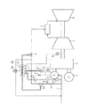
FIG. 4 is a detailed system diagram of the gas turbine power generation facility according to the first embodiment of the present invention. FIG. 5 is an explanatory diagram of the discharge pressure of the boost compressor used in the gas turbine power generation facility according to the first embodiment of the present invention. The same reference numerals as those in FIG. 2 indicate the same parts.
図4に示す構成では、図3の構成に加えて、圧力計17,18によって検出される圧力やガスタービンの運転状態に応じて、燃料流量調節弁9や、起動用燃料供給弁12や、アンチサージ弁24を制御する制御装置14を備えている。
In the configuration shown in FIG. 4, in addition to the configuration in FIG. 3, depending on the pressure detected by the pressure gauges 17 and 18 and the operating state of the gas turbine, the fuel flow
起動用燃料供給弁12は、ブースト圧縮機6と逆止弁8が直列に接続された系統に対して並列に設けられたバイパス系統15に設けられている。そして、ガスタービンの回転数が低い起動過程においては、起動用燃料供給弁12を開いて、パイパス系統15から燃焼器2に燃料である天然ガスを供給する。
The starting
ここで、図5を用いて、ブースト圧縮機の吐出圧について説明する。図5の横軸はタービン1の回転数を示し、縦軸はブースト圧縮機6の吐出圧を示している。図5に示すように、ガスタービンの回転数が低い起動過程においては、ブースト圧縮機6の回転数も低いために、ブースト圧縮機6による昇圧効果よりもブースト圧縮機6自体が抵抗体となり、圧力損失を発生する影響が大きく、ブースト圧縮機6の吐出圧力のほうが、燃料ガス採掘時の圧力よりも低くなる場合がある。この場合、十分昇圧されずに必要な燃料を燃焼器に供給できない可能性がある。そこで、図4も示したように、ブースト圧縮機6をバイパスして燃焼器2へ燃料ガスを供給するバイパス系統15を設ける。起動時の着火回転数からブースト圧縮機6の吐出圧力が上昇するまでの低速運転時の間、制御装置14は、起動用燃料ガス供給弁12を開き、バイパス系統15から燃料が供給されるようにする。この起動用のバイパス系統15はタービン回転数が上昇し、ブースト圧縮機6の吐出圧力が上昇するまでの間に使用する。ブースト圧縮機6の吐出圧が上昇したら、制御装置14は、起動用燃料ガス供給弁12を閉じてバイパス系統15燃料を供給することを止めて、ブースト圧縮機6を通してのみから燃料を燃焼器2へ供給する。
Here, the discharge pressure of the boost compressor will be described with reference to FIG. The horizontal axis in FIG. 5 indicates the rotational speed of the turbine 1, and the vertical axis indicates the discharge pressure of the
具体的には、制御装置14は、圧力計18によって計測された燃料ガス昇圧五の圧縮機6の吐出圧力と、圧力計17によって計測された,ガス田から採掘された燃料ガス圧力を比較し、圧縮機6の吐出圧が採掘されガス圧力よりも高くなると、起動用燃料ガス供給弁12の開度を閉にする。
Specifically, the
なお、圧力計17,18を用いる方法に代えて、タービン1の回転数を検出するタービン回転数計31や、圧縮機6の回転数を検出する圧縮機回転数計32を用いることができる。すなわち、発電設備の試運転時に、ブースト圧縮機6、ガスタービン圧縮機1の吐出圧力とタービン回転数の特性を計測して、図5に示したような特性を予め求める。そして、制御装置14は、回転数計31によって計測されたタービン回転数が、図5に示す回転数N4よりも低い場合,すなわち、圧縮機6の吐出圧が採掘されガス圧力よりも低い場合には、供給弁12を開き、タービン回転数が、回転数N4よりも高くなると、供給弁12を閉じる。また、回転数計32によって計測された圧縮機6の回転数と、変速機4のギア比により、タービン回転数が求まるため、回転数計32によって計測された圧縮機6の回転数によっても、供給弁12の開閉を制御することができる。同様にして、発電機回転数を用いることもできる。
Instead of using the pressure gauges 17 and 18, a
次に、アンチサージ弁24について説明する。ガスタービンの昇速中や低負荷運転時には燃焼器2へと供給する燃料流量は、定格運転時より少ないものである。そのため、ブースト圧縮機6の圧力・流量特性によっては、サージ域での運転となる可能性がある。そこで、ブースト圧縮機6がサージ域で運転される事を防止するため、圧縮機6の出口側と入口側とを接続するアンチサージ系統22を設け、その途中にアンチサージ弁24を設ける。制御装置14は、ガスタービンの運転状態に応じて、アンチサージ弁12を制御して、アンチサージ系統22を利用して流量を確保することで、ガスタービンの起動から定格負荷まで全域において安定した運転をすることができる。
Next, the
また、ガスタービンの起動から着火回転数に達するまでは、駆動用モータでガスタービン回転数を上げるため、このときは、制御装置14は、燃料供給調節弁9を閉じることになる。一方、ガスタービンの回転数が上がると、圧縮機6の吐出が締切状態になる。そこで、起動から着火回転数に到達するまでは、制御装置14は、アンチサージ弁24を開くことにより、締切状態での運転を回避することができる。なお、このとき、アンチサージ弁24に代えて、燃料供給弁12を開いても、図示の矢印R1の流路を形成して、締切状態を回避することができる。つまり、起動・着火・昇速して燃料ガス昇圧圧縮機の吐出圧力が上昇し、バイパス系統からの燃料供給を停止した後には、起動用燃料ガス供給弁12をアンチサージ弁として使用する。弁12を起動用燃料ガス供給とアンチサージの2つの目的に使用することにより燃料ガス昇圧圧縮機廻りの系統構成を簡略化でき低コスト化が図れる。
In addition, since the rotation speed of the gas turbine is increased by the drive motor from the start of the gas turbine until the ignition rotation speed is reached, the
さらに、タービン停止時には、制御装置14は、燃料遮断と同時にアンチサージ弁24を開くことで、燃料ガス昇圧圧縮機6の締切運転を防止する。これにより、安全にガスタービンを停止することが可能となる。
Further, when the turbine is stopped, the
なお、以上の説明では、老朽ガス田を例にして説明したが、油田で石油採掘時に同時に得られる随伴ガスについても、ガスタービン発電設備を用いて有効利用することができる。 In the above description, an old gas field has been described as an example. However, accompanying gas obtained at the same time as oil drilling in the oil field can also be effectively used by using the gas turbine power generation facility.
以上説明したように、本実施形態によれば、老朽ガス田という特殊な使用状況においても、従来使用していたパイプラインや液化設備、輸送設備を介さずに、老朽ガス田で発生している天然ガスを、老朽ガス田近傍に配置したガスタービン発電設備を用いて発電して電気を消費地に送ることにより、従来放置されていたガスを有効に利用することができる。新たに設置した発電設備の設置費用は、発電によって得られた電気を売ることにより回収でき、利益を得ることができる。また、これにより、パイプラインや液化設備、輸送設備の補修、管理、維持費を削減できる。 As described above, according to the present embodiment, even in a special usage situation of an aged gas field, it is generated in an aged gas field without going through the pipeline, liquefaction facility, and transport facility that have been used conventionally. By using natural gas to generate electricity using a gas turbine power generation facility arranged in the vicinity of an old gas field and sending electricity to a consumption area, it is possible to effectively use gas that has been left unattended. The installation cost of the newly installed power generation facility can be recovered by selling the electricity obtained by power generation, and profits can be obtained. This also reduces repair, management and maintenance costs for pipelines, liquefaction facilities, and transport facilities.
さらに、ガスタービンの軸から増速機を介して燃料ガスブースト圧縮機を駆動し、かつガスタービンの軸から減速機を介して発電機を駆動し、それら増速機と減速機を一体化した変速機とすることで、老朽ガス田に対応できる高信頼性で高効率、コンパクトなガスタービンとすることができる。老朽ガス田や油田では既設プラント設備が存在し、そこにガスタービンを設置することになるので、発電設備をコンパクト化できることにより、敷地の有効利用を図れる。 Furthermore, the fuel gas boost compressor is driven from the shaft of the gas turbine via the speed increaser, and the generator is driven from the shaft of the gas turbine via the speed reducer, so that the speed increaser and the speed reducer are integrated. By using a transmission, it is possible to provide a highly reliable, highly efficient and compact gas turbine that can cope with an old gas field. Existing plant facilities exist in old gas fields and oil fields, and gas turbines will be installed there, so that the power generation facilities can be made compact so that the site can be used effectively.
次に、図6を用いて、本発明の第2の実施形態によるガスタービン発電設備の具体的構成について説明する。
図6は、本発明の第2の実施形態によるガスタービン発電設備の詳細系統図である。なお、図4と同一符号は、同一部分を示している。
Next, a specific configuration of the gas turbine power generation facility according to the second embodiment of the present invention will be described with reference to FIG.
FIG. 6 is a detailed system diagram of the gas turbine power generation facility according to the second embodiment of the present invention. The same reference numerals as those in FIG. 4 indicate the same parts.
本実施形態の特徴は、バイパス系統15に、昇圧圧縮機21および、この昇圧圧縮機21を駆動するモータ33を設けたものである。ガス田で採掘される燃料ガス圧力が低く、前述のように起動用の燃料ガスを供給する為のバイパス系統15を利用しても燃焼器2に燃料ガスを供給できない場合、起動用バイパス系統15に起動時のみ使用する昇圧圧縮機21を設置する。この圧縮機は起動時の短時間のみに使用されるので供給流量が小さく、且つ必要とされる吐出圧力も小さいので必要とされるモータ33の動力は、ブースト圧縮機6の定格時動力に比べて小さくできる。また、小型の圧縮機であるので設置スペースもそれほど大きなものではないものである。
The feature of this embodiment is that the
ここで、燃料を供給するのは着火回転数到達後であるので、制御装置14Aは、着火回転数到達後に、モータ22を駆動して燃料ガス起動用昇圧圧縮機21は起動すれば良いものである。或いは、ガスタービンの起動時間短縮のため、あらかじめ起動用昇圧圧縮機21が起動するのに必要な時間を見込んで起動させても良いものである。これにより、ガスタービンが着火回転数到達した時に起動用昇圧圧縮機21の吐出圧が必要な圧力を確立しているようにする。ガスタービンの燃焼器2に着火・昇速後、前述したように燃料ガス昇圧圧縮機6の吐出圧力が燃焼器に燃料を供給するのに十分な圧力まで上昇した後、制御装置14Aは、供給弁12を閉じて、起動用バイパス系統15からの燃料供給を止めて、ブースト圧縮機6側の通常の燃料ガス供給系統から燃料供給し、起動用昇圧圧縮機21を停止する。これにより、起動時に十分な圧力の燃料をガスタービンに供給できるので、燃焼器の失火等の生じない信頼性の高いガスタービン起動が可能となる。
Here, since the fuel is supplied after reaching the ignition speed, the
以上説明したように、本実施形態によれば、老朽ガス田のガス圧がさらに低い場合でも、起動用昇圧圧縮機を用いて、ガスタービンを起動でき、従来放置されていたガスを有効に利用することができる。 As described above, according to the present embodiment, even when the gas pressure of an aging gas field is even lower, the gas turbine can be started using the boosting compressor for starting, and the gas that has been left unattended can be used effectively. can do.
次に、図7を用いて、本発明の第3の実施形態によるガスタービン発電設備の具体的構成について説明する。
図7は、本発明の第3の実施形態によるガスタービン発電設備の詳細系統図である。なお、図4と同一符号は、同一部分を示している。
Next, a specific configuration of the gas turbine power generation facility according to the third embodiment of the present invention will be described with reference to FIG.
FIG. 7 is a detailed system diagram of a gas turbine power generation facility according to the third embodiment of the present invention. The same reference numerals as those in FIG. 4 indicate the same parts.
本実施形態では、タンク36及びタンク36と圧縮機6との間の系統に備えられた開閉弁11を備えている。起動から着火回転数に到達するまでの間は、駆動用モータでガスタービン回転数を上げていくので、このときはガスタービンに燃料を供給する必要は無いため、燃料調節弁9を全閉として運転することになる。しかしながら、燃料ガスのブースト圧縮機6の吐出が締切状態での運転となるので圧縮機の温度が上昇するなどの機器保護上問題がある。ブースト圧縮機6をガスタービン回転軸に連結することにより本来停止しておきたいブースト圧縮機が回転してしまうことに起因しているのである。このため、ブースト圧縮機6の吐出系統を、起動から着火回転数に到達するまでは、制御装置14Bは、開閉弁11を開いて、ブースト圧縮機6が供給する燃料ガスを収容可能な量を備えた小型のタンク36に接続して起動時の数分間の燃料ガスはタンク36へと逃がし圧縮機を締切運転から保護する。ガスタービンが昇速して着火回転数に到達したら、制御装置14Bは、タンク36に接続された開閉弁を閉じ、燃焼器2に接続された調節弁9を開いて、燃焼器2に燃料ガスを供給して着火操作を行う。この方法により、ブースト圧縮機6は締め切り運転されることが無くなり、信頼性が向上する。
In this embodiment, the on-off
以上説明したように、本実施形態によれば、老朽ガス田のガス圧がさらに低い場合でも、起動用昇圧圧縮機を用いて、ガスタービンを起動でき、従来放置されていたガスを有効に利用することができるとともに、締め切り運転を回避することができる。 As described above, according to the present embodiment, even when the gas pressure of an aging gas field is even lower, the gas turbine can be started using the boosting compressor for starting, and the gas that has been left unattended can be used effectively. And the deadline operation can be avoided.
次に、図8を用いて、本発明の第4の実施形態によるガスタービン発電設備の具体的構成について説明する。
図8は、本発明の第4の実施形態によるガスタービン発電設備の詳細系統図である。なお、図4と同一符号は、同一部分を示している。
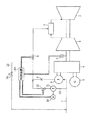
Next, a specific configuration of the gas turbine power generation facility according to the fourth embodiment of the present invention will be described with reference to FIG.
FIG. 8 is a detailed system diagram of a gas turbine power generation facility according to the fourth embodiment of the present invention. The same reference numerals as those in FIG. 4 indicate the same parts.
本実施形態では、ブースト圧縮機に燃料供給する系統に設けた切り替え弁91と、ガスタービン圧縮機1の吐出側と燃料ブースト圧縮機6の入口側を接続する系統34に設けられた調節弁13及び逆止弁23とを備えている。図7にて説明したブースト圧縮機6の締切運転防止のためは、制御装置14Cは、ブースト圧縮機に燃料供給する系統7に設けた切り替え弁91を閉として、系統34に設けた抽気弁13を開いて、ガスタービン圧縮機1の吐出空気または抽気空気を燃料ブースト圧縮機6へと供給し、燃焼器2に空気を流すことにより圧縮機6の保護に必要な流量を確保する。ガスタービン着火回転数に達した後は、制御装置14Cは、抽気弁13を閉じて切り替え弁91を開き、燃料調節弁9を開いて開度を調整する。供給される燃料を着火し、さらに必要な燃料ガスの流量を燃焼器2へと供給することにより昇速・負荷上昇させる。この方法により、ブースト圧縮機6は締め切り運転されることが無くなり、信頼性が向上する。
In the present embodiment, the switching
以上説明したように、本実施形態によれば、老朽ガス田のガス圧がさらに低い場合でも、起動用昇圧圧縮機を用いて、ガスタービンを起動でき、従来放置されていたガスを有効に利用することができるとともに、締め切り運転を回避することができる。 As described above, according to the present embodiment, even when the gas pressure of an aging gas field is even lower, the gas turbine can be started using the boosting compressor for starting, and the gas that has been left unattended can be used effectively. And the deadline operation can be avoided.
以上説明した本発明の各実施形態によると、次のような効果が得られる。老朽ガス田で採掘量が低下している場合は今まで使用していたパイプラインや液化設備、輸送設備を維持し、経済的に成立するだけの利益を確保することが難しくなる。よって、従来使用していたパイプラインや液化設備、輸送設備を介さずに、老朽ガス田で発生している天然ガスをその場で発電して電気を消費地に送るほうが経済的に有利になってくる。また、新たに設置した発電設備費は電気を売ることにより回収でき、利益をあげることができる。 According to each embodiment of the present invention described above, the following effects are obtained. When the mining volume is decreasing in an old gas field, it will be difficult to maintain the pipeline, liquefaction facility, and transport facility that have been used so far, and to secure profits that are economically feasible. Therefore, it would be economically advantageous to generate natural gas generated in an old gas field on the spot and send electricity to the consumption area without using the pipelines, liquefaction facilities, and transport facilities that were previously used. Come. Also, newly installed power generation equipment costs can be recovered by selling electricity, and profits can be made.
また、ガスタービン軸から増速機を介して駆動力を燃料ブースト圧縮機に伝えることにより、ブースト圧縮機をガスタービンの一部とすることができ、設備をコンパクトにできる利点がある。また、ブースト圧縮機をモータ等で駆動する場合に比べて、ガスタービンの軸力で直接駆動するので損失が少なく高効率が達成できる。さらに、軸駆動のブースト圧縮機をガスタービンの一部として備えたガスタービンを老朽ガス田の近傍に設置して、発電により電気を消費地に供給することにより、従来使用していなかった少量で圧力の低い天然ガスを有効に利用することができる。 Further, by transmitting the driving force from the gas turbine shaft to the fuel boost compressor via the speed increaser, the boost compressor can be made a part of the gas turbine, and there is an advantage that the equipment can be made compact. Further, since the boost compressor is directly driven by the axial force of the gas turbine as compared with the case where the boost compressor is driven by a motor or the like, the loss can be reduced and high efficiency can be achieved. Furthermore, by installing a gas turbine equipped with a shaft-driven boost compressor as a part of the gas turbine in the vicinity of an old gas field and supplying electricity to the consumption area by power generation, a small amount that has not been used conventionally Natural gas with low pressure can be used effectively.
ガスタービンの軸から増速機を介して直接に燃料ガスブースト圧縮機を駆動し、かつガスタービンの軸から減速機を介して直接に発電機を駆動し、それら増速機と減速機を一体化した変速機とすることで、老朽ガス田に対応できる高信頼性で高効率、コンパクトなガスタービンとすることができる。老朽ガス田や油田では既設プラント設備が存在し、そこにガスタービンを設置することになるので、前記のようにコンパクト化できるので敷地の有効利用が図れる。 The fuel gas boost compressor is directly driven from the shaft of the gas turbine through the speed increaser, and the generator is directly driven from the shaft of the gas turbine through the speed reducer. The speed increaser and the speed reducer are integrated. By adopting an improved transmission, a highly reliable, highly efficient and compact gas turbine that can cope with an old gas field can be obtained. In old gas fields and oil fields, there are existing plant facilities, and gas turbines are installed there, so that the site can be made more compact and the site can be used effectively.
一方で起動から着火回転数に到達するまでの間は、駆動用モータでガスタービン回転数を上げていくので、このときはガスタービンに燃料を供給する必要は無い。この為、燃料調節弁を全閉として運転することになる。しかしながら、燃料ガスのブースト圧縮機の吐出が締切状態での運転となるので圧縮機の機器保護上問題がある。この為、ブースト圧縮機の吐出系統を小型のタンクに接続して起動時の数分間の燃料ガスはタンクへと逃がし圧縮機を締切運転から保護する。ガスタービンが昇速して着火回転数に到達したらタンクと燃焼器への燃料ガス供給切替弁を操作して、燃焼器へと燃料ガスを供給して着火操作を行う。この方法により、ブースト圧縮機は締め切り運転されることが無くなり、燃料の温度上昇を防止でき信頼性が向上する。 On the other hand, since the rotation speed of the gas turbine is increased by the drive motor from the start to the ignition rotation speed, it is not necessary to supply fuel to the gas turbine at this time. For this reason, the fuel control valve is operated with the valve fully closed. However, since the fuel gas boost compressor is discharged in a closed state, there is a problem in protecting the compressor. For this reason, the discharge system of the boost compressor is connected to a small tank, and fuel gas for several minutes at the time of start-up escapes to the tank to protect the compressor from the shut-off operation. When the gas turbine is accelerated and reaches the ignition rotation speed, the fuel gas supply switching valve to the tank and the combustor is operated to supply the fuel gas to the combustor to perform the ignition operation. This method eliminates the deadline operation of the boost compressor, prevents an increase in fuel temperature, and improves reliability.
また、ブースト圧縮機の締切運転防止のために、前述するようなタンクを用いずにガスタービン圧縮機の吐出空気または抽気空気を燃料ブースト圧縮機へと供給し、燃焼器に空気を流すことによりブースト圧縮機保護の為に必要な流量を確保する。ガスタービン着火回転数に達した後は、抽気弁を閉じて燃料調節弁を開き開度を調整する。供給される燃料を着火し、さらに必要な燃料ガスの流量を燃焼器へと供給することにより昇速・負荷上昇させる。この方法により、ブースト圧縮機は締め切り運転されることが無くなり、信頼性が向上する。 In order to prevent the boost compressor from shutting down, the discharge air or bleed air from the gas turbine compressor is supplied to the fuel boost compressor without using the tank as described above, and the air is allowed to flow through the combustor. Ensure the necessary flow rate for boost compressor protection. After reaching the gas turbine ignition speed, the bleed valve is closed and the fuel control valve is opened to adjust the opening. The fuel to be supplied is ignited, and the flow rate of the required fuel gas is supplied to the combustor to increase the speed and load. This method eliminates the deadline operation of the boost compressor and improves the reliability.
さらに、ガスタービンの回転数が低い起動過程においては、ブースト圧縮機の回転数も低いために、ブースト圧縮機による昇圧効果よりもブースト圧縮機自体が抵抗体となり圧力損失を発生する影響が大きく、ブースト圧縮機吐出圧力のほうが、燃料ガス採掘時の圧力よりも低くなる可能性がある。この場合、十分昇圧されずに必要な燃料を燃焼器に供給できない可能性がある。このような場合にはブースト圧縮機をバイパスして燃焼器へ燃料ガスを供給する系統を設ける。これにより、起動時の着火回転数からブースト圧縮機の吐出圧力が上昇するまでの低速運転時の燃料を供給でき、信頼性の高い運転が可能となる。 Furthermore, in the start-up process where the rotational speed of the gas turbine is low, the rotational speed of the boost compressor is also low, so that the boost compressor itself becomes a resistor rather than the boosting effect by the boost compressor and the pressure loss is greatly affected. The boost compressor discharge pressure may be lower than the pressure during fuel gas mining. In this case, there is a possibility that necessary fuel cannot be supplied to the combustor without sufficiently increasing the pressure. In such a case, a system that bypasses the boost compressor and supplies fuel gas to the combustor is provided. Thereby, the fuel at the time of the low speed driving | operation until the discharge pressure of a boost compressor rises from the ignition rotation speed at the time of starting can be supplied, and a reliable driving | operation is attained.
しかし、ガス田で採掘される燃料ガス圧力が低く、前述するような起動用の燃料ガスを供給する為のバイパス系統を利用しても燃焼器に燃料ガスを供給できない場合、起動用バイパス系統に起動時のみ使用する昇圧圧縮機を設置する。これにより、圧力の低い起動時でも十分な燃料を供給することができる。 However, if the pressure of the fuel gas excavated in the gas field is low and the fuel gas cannot be supplied to the combustor even when using the bypass system for supplying the startup fuel gas as described above, the startup bypass system is Install a booster compressor that is used only at startup. Thereby, sufficient fuel can be supplied even at the start-up time when the pressure is low.
また、ガスタービンの昇速中や低負荷運転時には燃焼器へと供給する燃料流量が少ない。この為、ブースト圧縮機の圧力・流量特性によっては、サージ域での運転となる可能性がある。この場合のブースト圧縮機がサージ域で運転される事を防止する為にアンチサージ系統を設ける。アンチサージ系統を利用して流量を確保することでガスタービンの起動から定格負荷まで全域において安定した運転をすることができる。 In addition, the fuel flow rate supplied to the combustor is small during gas turbine acceleration or low load operation. For this reason, depending on the pressure / flow rate characteristics of the boost compressor, there is a possibility of operation in the surge region. In order to prevent the boost compressor in this case from operating in the surge region, an anti-surge system is provided. By securing the flow rate using the anti-surge system, stable operation can be performed in the entire region from the start of the gas turbine to the rated load.
以上示してきたように発電機とブースト圧縮機の変速機を一体化した設備を使用し、圧力の低い老朽ガス田の天然ガスを使用するために生じる起動過程の問題を解決することで、これまで有効利用されなかった老朽化したガス田より採掘される低圧の燃料ガスを利用してガスタービンで発電することができる。
As mentioned above, this is achieved by using the equipment that integrates the generator and the transmission of the boost compressor and solving the problem of the startup process that occurs due to the use of natural gas from an old gas field with low pressure. It is possible to generate power with a gas turbine using low-pressure fuel gas mined from an old gas field that has not been used effectively until now.
1…圧縮機
2…燃焼器
3…タービン
4…変速機
4a…発電機用減速機
4b…燃料ガスブースト圧縮機用増速機
5…発電機
6…燃料ガスブースト圧縮機
7…燃料ガス供給系統
8,23…逆止弁
9…燃料流量調節弁
11…起動用バイパス弁
12…起動用燃料供給弁
13…空気供給弁
14…制御装置
15…起動用燃料供給系統
16…燃料供給系統
17,18…圧力計
19…燃料昇圧圧縮機回転数計
20…タービン回転数計
21…起動用燃料昇圧圧縮機
22…アンチサージ系統
24…アンチサージ弁
31…タービン回転数計
32…圧縮機回転数計
33…モータ
34…系統
36…タンク
DESCRIPTION OF SYMBOLS 1 ... Compressor 2 ... Combustor 3 ... Turbine 4 ...
Claims (1)
前記ガスタービンは圧縮機にて圧縮した空気を燃焼器に導き、燃料と混合させた後に燃焼させて、その燃焼ガスによりタービンを駆動し、さらに前記ガスタービンの回転軸から得られる動力で発電機を駆動するガスタービンであり、
前記ガスタービンの回転軸から得られる動力で駆動するブースト圧縮機と、
前記ガスタービンの前記圧縮機の出口もしくは途中から前記ブースト圧縮機入口に至る空気系統と、
前記空気系統に設置された抽気弁と、
前記ブースト圧縮機入口側であって、前記空気系統の接続位置よりも上流に設置された切り替え弁とを備え、
前記天然ガスもしくは随伴ガスを燃料として前記ブースト圧縮機で昇圧し燃焼器に供給することを特徴とするガスタービン発電設備。 It has a gas turbine installed near an old gas field or an oil field, and it uses the natural gas generated in the old gas field or the accompanying gas generated in the oil field to generate electricity and supply the electricity obtained to the consumption area. Gas turbine power generation equipment
The gas turbine introduces air compressed by a compressor to a combustor, and mixes it with fuel, burns it, drives the turbine with the combustion gas, and further generates power with power obtained from the rotating shaft of the gas turbine. A gas turbine that drives
A boost compressor driven by power obtained from the rotating shaft of the gas turbine;
An air system leading from the compressor outlet of the gas turbine or midway to the boost compressor inlet;
A bleed valve installed in the air system;
A switching valve installed on the boost compressor inlet side and upstream of the connection position of the air system;
A gas turbine power generation facility characterized in that the natural gas or associated gas is boosted by the boost compressor as fuel and supplied to a combustor.
Priority Applications (4)
| Application Number | Priority Date | Filing Date | Title |
|---|---|---|---|
| JP2003370324A JP4068546B2 (en) | 2003-10-30 | 2003-10-30 | Gas turbine power generation facility and operation method thereof |
| EP04019183A EP1528237A3 (en) | 2003-10-30 | 2004-08-12 | Gas-turbine power generating installation and method of operating the same |
| US10/917,285 US7114322B2 (en) | 2003-10-30 | 2004-08-13 | Gas-turbine power generating installation and method of operating the same |
| US11/438,435 US7472542B2 (en) | 2003-10-30 | 2006-05-23 | Gas-turbine power generating installation and method of operating the same |
Applications Claiming Priority (1)
| Application Number | Priority Date | Filing Date | Title |
|---|---|---|---|
| JP2003370324A JP4068546B2 (en) | 2003-10-30 | 2003-10-30 | Gas turbine power generation facility and operation method thereof |
Publications (2)
| Publication Number | Publication Date |
|---|---|
| JP2005133630A JP2005133630A (en) | 2005-05-26 |
| JP4068546B2 true JP4068546B2 (en) | 2008-03-26 |
Family
ID=34420195
Family Applications (1)
| Application Number | Title | Priority Date | Filing Date |
|---|---|---|---|
| JP2003370324A Expired - Fee Related JP4068546B2 (en) | 2003-10-30 | 2003-10-30 | Gas turbine power generation facility and operation method thereof |
Country Status (3)
| Country | Link |
|---|---|
| US (2) | US7114322B2 (en) |
| EP (1) | EP1528237A3 (en) |
| JP (1) | JP4068546B2 (en) |
Families Citing this family (24)
| Publication number | Priority date | Publication date | Assignee | Title |
|---|---|---|---|---|
| US7272932B2 (en) * | 2002-12-09 | 2007-09-25 | Dresser, Inc. | System and method of use of expansion engine to increase overall fuel efficiency |
| JP4068546B2 (en) * | 2003-10-30 | 2008-03-26 | 株式会社日立製作所 | Gas turbine power generation facility and operation method thereof |
| JP4581563B2 (en) * | 2004-08-31 | 2010-11-17 | 株式会社日立製作所 | Combined cycle power generation facilities, steam power generation facilities |
| JP4509742B2 (en) * | 2004-11-04 | 2010-07-21 | 株式会社日立製作所 | Gas turbine power generation equipment |
| DE102005050573A1 (en) * | 2005-10-21 | 2007-04-26 | Eco Naturgas Handels Gmbh | Use of a turbocompressor for recovering energy from a pressurized gas |
| USRE46725E1 (en) | 2009-09-11 | 2018-02-20 | Halliburton Energy Services, Inc. | Electric or natural gas fired small footprint fracturing fluid blending and pumping equipment |
| US20110303390A1 (en) * | 2010-06-14 | 2011-12-15 | Vykson Limited | Combustion Chamber Cooling Method and System |
| PL2726705T3 (en) | 2011-04-07 | 2019-01-31 | Evolution Well Services, Llc | Mobile, modular, electrically powered system for use in fracturing underground formations |
| US11708752B2 (en) | 2011-04-07 | 2023-07-25 | Typhon Technology Solutions (U.S.), Llc | Multiple generator mobile electric powered fracturing system |
| US11255173B2 (en) | 2011-04-07 | 2022-02-22 | Typhon Technology Solutions, Llc | Mobile, modular, electrically powered system for use in fracturing underground formations using liquid petroleum gas |
| US9140110B2 (en) | 2012-10-05 | 2015-09-22 | Evolution Well Services, Llc | Mobile, modular, electrically powered system for use in fracturing underground formations using liquid petroleum gas |
| US9869305B1 (en) | 2013-03-14 | 2018-01-16 | Tucson Embedded Systems, Inc. | Pump-engine controller |
| US9377202B2 (en) | 2013-03-15 | 2016-06-28 | General Electric Company | System and method for fuel blending and control in gas turbines |
| US9382850B2 (en) | 2013-03-21 | 2016-07-05 | General Electric Company | System and method for controlled fuel blending in gas turbines |
| US9551278B2 (en) | 2014-07-16 | 2017-01-24 | Air Products And Chemicals, Inc. | Hydrogen production system and process |
| AU2015364678B2 (en) | 2014-12-19 | 2018-11-22 | Typhon Technology Solutions, Llc | Mobile electric power generation for hydraulic fracturing of subsurface geological formations |
| US10063092B2 (en) * | 2015-10-02 | 2018-08-28 | Facebook, Inc. | Data center power network with multiple redundancies |
| US20170143999A1 (en) * | 2015-11-25 | 2017-05-25 | David A. POMEROY | Wrist-worn glass breaking tool |
| KR102132057B1 (en) * | 2016-06-17 | 2020-07-09 | 한국조선해양 주식회사 | Anti-surge valve control method of Multi gas Compressor Systems |
| MX2021013179A (en) | 2019-05-01 | 2021-12-10 | Typhon Tech Solutions Llc | Single-transport mobile electric power generation. |
| US11512632B2 (en) | 2019-05-01 | 2022-11-29 | Typhon Technology Solutions (U.S.), Llc | Single-transport mobile electric power generation |
| CN113700550B (en) * | 2021-08-31 | 2024-04-09 | 中国船舶重工集团公司第七0三研究所 | Anti-surge method for air bypass baffle of turbocharger unit |
| US11725582B1 (en) | 2022-04-28 | 2023-08-15 | Typhon Technology Solutions (U.S.), Llc | Mobile electric power generation system |
| US11955782B1 (en) | 2022-11-01 | 2024-04-09 | Typhon Technology Solutions (U.S.), Llc | System and method for fracturing of underground formations using electric grid power |
Family Cites Families (32)
| Publication number | Priority date | Publication date | Assignee | Title |
|---|---|---|---|---|
| GB765270A (en) * | 1954-03-06 | 1957-01-09 | Sulzer Ag | Gas turbine plants |
| US4087961A (en) * | 1976-07-21 | 1978-05-09 | Woodward Governor Company | Fuel control system for gas turbine engine operated on gaseous fuel |
| EP0029075A1 (en) | 1979-11-14 | 1981-05-27 | BBC Aktiengesellschaft Brown, Boveri & Cie. | Gas turbine with an auxiliary combustible gas compressor |
| GB2117053B (en) * | 1982-02-18 | 1985-06-05 | Boc Group Plc | Gas turbines and engines |
| JPS60222531A (en) * | 1984-04-20 | 1985-11-07 | Mitsui Eng & Shipbuild Co Ltd | Gas turbine driving system with fuel gas compressor |
| JP2665000B2 (en) * | 1989-08-31 | 1997-10-22 | 三菱重工業株式会社 | Combined engine |
| DE4210544A1 (en) * | 1992-03-31 | 1993-10-07 | Asea Brown Boveri | Gas turbine plant |
| GB2291682A (en) * | 1993-06-23 | 1996-01-31 | Shell Int Research | Gas turbine using low-btu fuel |
| RU94026102A (en) * | 1993-07-22 | 1996-06-10 | Ормат Индастриз Лтд. (Il) | System for reducing pressure and regenerating energy |
| US5685155A (en) * | 1993-12-09 | 1997-11-11 | Brown; Charles V. | Method for energy conversion |
| JP3658415B2 (en) * | 1993-12-28 | 2005-06-08 | 株式会社 日立インダストリイズ | Gas turbine equipment |
| US5740667A (en) * | 1994-12-15 | 1998-04-21 | Amoco Corporation | Process for abatement of nitrogen oxides in exhaust from gas turbine power generation |
| DE19549140A1 (en) * | 1995-12-29 | 1997-07-03 | Asea Brown Boveri | Method for operating a gas turbine group with low-calorific fuel |
| US5819524A (en) * | 1996-10-16 | 1998-10-13 | Capstone Turbine Corporation | Gaseous fuel compression and control system and method |
| US6216441B1 (en) * | 1997-09-17 | 2001-04-17 | General Electric Co | Removal of inert gases from process gases prior to compression in a gas turbine or combined cycle power plant |
| US6167692B1 (en) * | 1998-06-29 | 2001-01-02 | General Electric Co. | Method of using fuel gas expander in power generating plants |
| US6161386A (en) * | 1998-12-23 | 2000-12-19 | Membrane Technology And Research, Inc. | Power generation method including membrane separation |
| JP2002259734A (en) | 2001-02-28 | 2002-09-13 | Hitachi Ltd | Method and system for providing solution service information on natural gas |
| JP2002327629A (en) | 2001-04-27 | 2002-11-15 | Toshiba Corp | Gas turbine generator and gas fuel pressurizing device for the same |
| JP3939509B2 (en) | 2001-07-26 | 2007-07-04 | 月島機械株式会社 | Method and apparatus for using gas |
| CA2465384C (en) * | 2001-11-09 | 2008-09-09 | Kawasaki Jukogyo Kabushiki Kaisha | Gas turbine system comprising closed system of fuel and combustion gas using underground coal bed |
| JP2003166428A (en) * | 2001-11-30 | 2003-06-13 | Toshiba Corp | Gas turbine generator and gas fuel booster applied thereto |
| CA2468769A1 (en) * | 2001-12-03 | 2003-06-12 | Clean Energy Systems, Inc. | Coal and syngas fueled power generation systems featuring zero atmospheric emissions |
| US6779333B2 (en) * | 2002-05-21 | 2004-08-24 | Conocophillips Company | Dual fuel power generation system |
| US6666027B1 (en) * | 2002-07-15 | 2003-12-23 | General Electric Company | Turbine power generation systems and methods using off-gas fuels |
| US6820427B2 (en) * | 2002-12-13 | 2004-11-23 | General Electric Company | Method and apparatus for operating a turbine engine |
| US20040226299A1 (en) * | 2003-05-12 | 2004-11-18 | Drnevich Raymond Francis | Method of reducing NOX emissions of a gas turbine |
| US7299638B2 (en) * | 2003-08-29 | 2007-11-27 | Robin Mackay | Combined heat and power system |
| US7076957B2 (en) * | 2003-09-05 | 2006-07-18 | Praxair Technology, Inc. | Fluid heating and gas turbine integration method |
| JP4068546B2 (en) * | 2003-10-30 | 2008-03-26 | 株式会社日立製作所 | Gas turbine power generation facility and operation method thereof |
| JP4581563B2 (en) * | 2004-08-31 | 2010-11-17 | 株式会社日立製作所 | Combined cycle power generation facilities, steam power generation facilities |
| JP4564376B2 (en) * | 2005-02-23 | 2010-10-20 | 株式会社東芝 | LNG power generation plant and its operation method |
-
2003
- 2003-10-30 JP JP2003370324A patent/JP4068546B2/en not_active Expired - Fee Related
-
2004
- 2004-08-12 EP EP04019183A patent/EP1528237A3/en not_active Withdrawn
- 2004-08-13 US US10/917,285 patent/US7114322B2/en active Active
-
2006
- 2006-05-23 US US11/438,435 patent/US7472542B2/en active Active
Also Published As
| Publication number | Publication date |
|---|---|
| US7472542B2 (en) | 2009-01-06 |
| EP1528237A2 (en) | 2005-05-04 |
| US7114322B2 (en) | 2006-10-03 |
| US20050091985A1 (en) | 2005-05-05 |
| US20060207260A1 (en) | 2006-09-21 |
| EP1528237A3 (en) | 2012-04-11 |
| JP2005133630A (en) | 2005-05-26 |
Similar Documents
| Publication | Publication Date | Title |
|---|---|---|
| JP4068546B2 (en) | Gas turbine power generation facility and operation method thereof | |
| US10815882B2 (en) | Integrated power generation and compression train, and method | |
| US6895325B1 (en) | Overspeed control system for gas turbine electric powerplant | |
| KR100313824B1 (en) | Gas turbine plant | |
| US10337409B2 (en) | Method for assisting a turboshaft engine in standby of a multiple-engine helicopter, and architecture of a propulsion system of a helicopter comprising at least one turboshaft engine that can be in standby | |
| US7043905B2 (en) | Gas energy conversion apparatus and method | |
| EP2559862B1 (en) | Control of a blow-off valve responsive to a sudden de-loading of a gas turbine | |
| JP5746361B2 (en) | Method for operating a gas turbine in case of partial power outage, device for controlling the operation of the gas turbine and power plant | |
| US20040088987A1 (en) | Integrated gas compressor | |
| JP2009047170A (en) | Combustion turbine cooling medium supply method | |
| CA2030268A1 (en) | Gas turbine control system having optimized ignition air flow control | |
| JP2008248875A (en) | Gas turbine power generation system and its operation control method | |
| EP3118435B1 (en) | Power augmentation system for a gas turbine using compressed air storage | |
| JP2013545022A (en) | Operation method of stationary gas turbine, operation adjusting device for gas turbine, and power plant | |
| JPH07189740A (en) | Gas turbine cooling system | |
| EP2746555B1 (en) | Fuel routing system of a gas turbine engine and method of routing fuel | |
| JP3623913B2 (en) | Gas-fired gas turbine generator | |
| US11459961B2 (en) | Method for operating a power plant, and power plant | |
| JP4934720B2 (en) | Natural gas liquefaction plant and power supply system, control device and operation method thereof | |
| CA2917623A1 (en) | Turbine engine control system | |
| RU2186224C2 (en) | Method and device for starting and supplying gas to gas-turbine power plant | |
| Quin˜ ones et al. | Test and evaluation of a gas turbine electric starter system | |
| McCarrick et al. | World’s First LM5000 to LM6000 Cogeneration Plant Repowering | |
| ROSENCRANCE | World’s First LM5000 to LM6000 Cogeneration Plant Repowering | |
| JPS63212773A (en) | Transient operation control method for branch aqueduct pumped storage power station |
Legal Events
| Date | Code | Title | Description |
|---|---|---|---|
| A621 | Written request for application examination |
Free format text: JAPANESE INTERMEDIATE CODE: A621 Effective date: 20051208 |
|
| A977 | Report on retrieval |
Free format text: JAPANESE INTERMEDIATE CODE: A971007 Effective date: 20070528 |
|
| A131 | Notification of reasons for refusal |
Free format text: JAPANESE INTERMEDIATE CODE: A131 Effective date: 20070605 |
|
| A521 | Request for written amendment filed |
Free format text: JAPANESE INTERMEDIATE CODE: A523 Effective date: 20070803 |
|
| A02 | Decision of refusal |
Free format text: JAPANESE INTERMEDIATE CODE: A02 Effective date: 20071002 |
|
| A521 | Request for written amendment filed |
Free format text: JAPANESE INTERMEDIATE CODE: A523 Effective date: 20071108 |
|
| A911 | Transfer to examiner for re-examination before appeal (zenchi) |
Free format text: JAPANESE INTERMEDIATE CODE: A911 Effective date: 20071210 |
|
| TRDD | Decision of grant or rejection written | ||
| A01 | Written decision to grant a patent or to grant a registration (utility model) |
Free format text: JAPANESE INTERMEDIATE CODE: A01 Effective date: 20080108 |
|
| A61 | First payment of annual fees (during grant procedure) |
Free format text: JAPANESE INTERMEDIATE CODE: A61 Effective date: 20080110 |
|
| FPAY | Renewal fee payment (event date is renewal date of database) |
Free format text: PAYMENT UNTIL: 20110118 Year of fee payment: 3 |
|
| R150 | Certificate of patent or registration of utility model |
Free format text: JAPANESE INTERMEDIATE CODE: R150 Ref document number: 4068546 Country of ref document: JP Free format text: JAPANESE INTERMEDIATE CODE: R150 |
|
| FPAY | Renewal fee payment (event date is renewal date of database) |
Free format text: PAYMENT UNTIL: 20110118 Year of fee payment: 3 |
|
| FPAY | Renewal fee payment (event date is renewal date of database) |
Free format text: PAYMENT UNTIL: 20120118 Year of fee payment: 4 |
|
| FPAY | Renewal fee payment (event date is renewal date of database) |
Free format text: PAYMENT UNTIL: 20130118 Year of fee payment: 5 |
|
| S111 | Request for change of ownership or part of ownership |
Free format text: JAPANESE INTERMEDIATE CODE: R313111 |
|
| R350 | Written notification of registration of transfer |
Free format text: JAPANESE INTERMEDIATE CODE: R350 |
|
| R250 | Receipt of annual fees |
Free format text: JAPANESE INTERMEDIATE CODE: R250 |
|
| R250 | Receipt of annual fees |
Free format text: JAPANESE INTERMEDIATE CODE: R250 |
|
| R250 | Receipt of annual fees |
Free format text: JAPANESE INTERMEDIATE CODE: R250 |
|
| R250 | Receipt of annual fees |
Free format text: JAPANESE INTERMEDIATE CODE: R250 |
|
| R250 | Receipt of annual fees |
Free format text: JAPANESE INTERMEDIATE CODE: R250 |
|
| R250 | Receipt of annual fees |
Free format text: JAPANESE INTERMEDIATE CODE: R250 |
|
| LAPS | Cancellation because of no payment of annual fees |