EP1635066B1 - Gas supply apparatus and associated method of operation for a gas turbine - Google Patents
Gas supply apparatus and associated method of operation for a gas turbine Download PDFInfo
- Publication number
- EP1635066B1 EP1635066B1 EP05107639.6A EP05107639A EP1635066B1 EP 1635066 B1 EP1635066 B1 EP 1635066B1 EP 05107639 A EP05107639 A EP 05107639A EP 1635066 B1 EP1635066 B1 EP 1635066B1
- Authority
- EP
- European Patent Office
- Prior art keywords
- compressor
- pressure
- 2soll
- pipeline
- consumer
- Prior art date
- Legal status (The legal status is an assumption and is not a legal conclusion. Google has not performed a legal analysis and makes no representation as to the accuracy of the status listed.)
- Not-in-force
Links
Images
Classifications
-
- F—MECHANICAL ENGINEERING; LIGHTING; HEATING; WEAPONS; BLASTING
- F02—COMBUSTION ENGINES; HOT-GAS OR COMBUSTION-PRODUCT ENGINE PLANTS
- F02C—GAS-TURBINE PLANTS; AIR INTAKES FOR JET-PROPULSION PLANTS; CONTROLLING FUEL SUPPLY IN AIR-BREATHING JET-PROPULSION PLANTS
- F02C7/00—Features, components parts, details or accessories, not provided for in, or of interest apart form groups F02C1/00 - F02C6/00; Air intakes for jet-propulsion plants
- F02C7/22—Fuel supply systems
- F02C7/224—Heating fuel before feeding to the burner
-
- F—MECHANICAL ENGINEERING; LIGHTING; HEATING; WEAPONS; BLASTING
- F02—COMBUSTION ENGINES; HOT-GAS OR COMBUSTION-PRODUCT ENGINE PLANTS
- F02C—GAS-TURBINE PLANTS; AIR INTAKES FOR JET-PROPULSION PLANTS; CONTROLLING FUEL SUPPLY IN AIR-BREATHING JET-PROPULSION PLANTS
- F02C7/00—Features, components parts, details or accessories, not provided for in, or of interest apart form groups F02C1/00 - F02C6/00; Air intakes for jet-propulsion plants
- F02C7/22—Fuel supply systems
-
- F—MECHANICAL ENGINEERING; LIGHTING; HEATING; WEAPONS; BLASTING
- F04—POSITIVE - DISPLACEMENT MACHINES FOR LIQUIDS; PUMPS FOR LIQUIDS OR ELASTIC FLUIDS
- F04D—NON-POSITIVE-DISPLACEMENT PUMPS
- F04D27/00—Control, e.g. regulation, of pumps, pumping installations or pumping systems specially adapted for elastic fluids
- F04D27/02—Surge control
- F04D27/0284—Conjoint control of two or more different functions
-
- F—MECHANICAL ENGINEERING; LIGHTING; HEATING; WEAPONS; BLASTING
- F05—INDEXING SCHEMES RELATING TO ENGINES OR PUMPS IN VARIOUS SUBCLASSES OF CLASSES F01-F04
- F05D—INDEXING SCHEME FOR ASPECTS RELATING TO NON-POSITIVE-DISPLACEMENT MACHINES OR ENGINES, GAS-TURBINES OR JET-PROPULSION PLANTS
- F05D2270/00—Control
- F05D2270/30—Control parameters, e.g. input parameters
- F05D2270/301—Pressure
-
- Y—GENERAL TAGGING OF NEW TECHNOLOGICAL DEVELOPMENTS; GENERAL TAGGING OF CROSS-SECTIONAL TECHNOLOGIES SPANNING OVER SEVERAL SECTIONS OF THE IPC; TECHNICAL SUBJECTS COVERED BY FORMER USPC CROSS-REFERENCE ART COLLECTIONS [XRACs] AND DIGESTS
- Y10—TECHNICAL SUBJECTS COVERED BY FORMER USPC
- Y10T—TECHNICAL SUBJECTS COVERED BY FORMER US CLASSIFICATION
- Y10T137/00—Fluid handling
- Y10T137/0318—Processes
- Y10T137/0324—With control of flow by a condition or characteristic of a fluid
- Y10T137/0329—Mixing of plural fluids of diverse characteristics or conditions
- Y10T137/0346—Controlled by heat of combustion of mixture
Definitions
- the present invention relates to a method for operating a gas supply system for a gas turbine with the features of the preamble of claim 1.
- the present invention also relates to a gas supply system for a gas turbine, having the features of the preamble of claim 7.
- the known gas supply system comprises a gas-conducting pipeline, a pipeline-mounted, controllable compressor and a pipeline connected to the compressor, downstream of the compressor, namely a gas turbine.
- a control device in the form of a regulator is provided, which regulates the compressor in dependence on a desired-actual comparison of a compressor outlet pressure.
- the controller can change the speed and / or the vane position of the compressor.
- the Compressor outlet pressure can be measured in the conventional manner at the compressor outlet.
- the compressor outlet nominal pressure is usually fixed, this preset value depending on the respective location of the gas turbine, in particular on the expected lowest ambient temperatures.
- the predetermined Kompressorauslasssolldruck results from the maximum gas turbine power and the maximum gas temperature and from the lower heating value of the gas.
- a throttle body is arranged in the pipeline, which is actuated by means of a separate regulator.
- a pressure change in the pipeline can be adjusted using the throttle body always a desired compressor inlet pressure, which allows the compressor to set the compressor discharge target pressure.
- the compressor can always be operated with high power, in particular with its rated power.
- this is not always useful for energetic reasons.
- compressors with a fixed compression ratio are used regularly here. If the pressure in the pipeline increases, the discharge pressure can reach inadmissibly high values unless the inlet pressure is regulated accordingly with the aid of the upstream throttle body. Such a compressor works permanently at full load or nominal load.
- From the DE 15 03 568 A1 is a compressor station for gaseous media, which serve to compensate for the pressure drop in the line to maintain a final pressure at the consumer known.
- the DE 103 41 758 A1 describes a gas compressor controller and a gas turbine engine control mechanism that can control a constant gas compressor discharge pressure to suppress a pressure increase of a fuel gas supplied to a gas turbine even if a load rejection or a load loss occurs.
- the present invention deals with the problem for a gas supply system of the above mentioned type to provide an improved embodiment and an improved operating method, whereby in particular a reduced energy consumption of the compressor is achieved.
- the present invention is based on the general idea to regulate the compressor in response to the consumer inlet pressure.
- the compressor can be operated directly depending on the actual needs, which makes it possible to reduce the power of the compressor according to a reduced pressure requirement. This can reduce the energy consumption of the compressor.
- the invention thus provides a feedback of the current power requirement of the gas turbine to the upstream gas supply system.
- the required consumer entry pressure is determined as a function of at least one current consumer parameter, e.g. its load state, and / or at least one current environmental parameter, such as the ambient temperature, determined.
- the required consumer inlet target pressure can be determined independently of the consumer or independently of an active feedback from the consumer.
- the gas supply system can work autonomously.
- the compressor discharge target pressure (p 2SOLL ) is determined as a function of a pressure drop which occurs in the pipeline between a compressor outlet and a consumer inlet.
- this Druckabsenk listening is required only if the pipeline pressure, that is, the compressor inlet pressure measured upstream of the pressure lowering device is greater than the determined compressor outlet nominal pressure. In this case, the excessively high pipeline pressure is throttled to the required compressor discharge nominal pressure with the aid of the pressure lowering device. At the same time, the compressor is deactivated so that it does not absorb any energy. In contrast, with smaller pipeline pressures the DruckabsenkINA is deactivated and generated by means of the compressor, the required pressure increase.
- bypasses may be provided which internally, so within the Druckabsenk recognized or within the compressor, or outside, ie by separate bypass lines, which extend in particular outside the compressor or the Druckabsenk sensible, may be formed ,
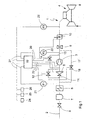
- FIG. 1 shows a greatly simplified, schematics-like schematic diagram of a gas supply system according to the invention.
- a gas supply system 1 comprises a pipeline 2, in which a compressor 3 is arranged and which is connected to a consumer 4.
- the consumer 4 is connected downstream of the compressor 3.
- the consumer 4 is a gas turbine, in particular for power generation in a power plant.
- a Druckabsenk Nurn 5 is connected upstream, by means of which in the pressure lowering device 5 by the gas flowing through the pressure can be selectively lowered.
- a dew-point heating device 6 is arranged, with the aid of which, at low ambient temperatures, the gas can be heated above the dew point of, if appropriate, entrained liquid.
- a separator 7 for separating particles and / or droplets carried by the gas flow.
- a check valve 8 is arranged, with the aid thereof, e.g. In case of emergency, the gas supply can be switched off completely.
- a fine filter 9 Downstream of the compressor 3, a fine filter 9 is arranged, with the help of small or fine-grained liquid or solid impurities can be filtered out of the gas flow. Downstream of this fine filter 9, a preheating device 10 is arranged, with the aid of which the gas flow can be heated to a predetermined temperature, if necessary.
- a first bypass 11 is also provided, which serves for bypassing or for low-resistance flow through the Druckabsenk issued 5.
- the first bypass 11 may be formed internally, that is, in the interior of the pressure lowering device 5.
- the first bypass 11 - as shown here - be formed by a separate bypass line.
- the first bypass 11 can be controlled, which is indicated here by a first control valve 12.
- this first control valve 12 can basically be dispensed with, since its function can be realized by a control or by actuators of the pressure lowering device 5.
- a second bypass 13 which serves for bypassing or for low-resistance flow through the compressor 3 and is also controllable.
- the second bypass 13 may be implemented internally, that is integrally in the compressor 3 or externally by a separate bypass line.
- the second bypass 13 is also directly or indirectly controllable via the compressor 3, which is indicated here by a second control valve 14.
- a third bypass 17 is provided which bypasses both the Druckabsenk Anlagen 5 and the compressor 3, externally, so with a separate bypass line is realized and with the aid of a third control valve 18 is controllable.
- This third bypass 17 is basically internally feasible.
- the gas supply system 1 is equipped with a control device 19 which controls the controllable or controllable components of the gas supply system 1 via a plurality of control lines 20, ie here the compressor 3, the pressure lowering device 5, the preheating device 10 and the three bypasses 11, 13, 17 and the control valves 12, 14, 18th
- the gas supply system 1 has a plurality of sensors, namely a first pressure sensor 21 for determining a compressor inlet pressure p 1IST , a second pressure sensor 22 for determining a compressor outlet pressure p 2IST, a third pressure sensor 23 for determining a consumer inlet pressure p 3IST and other sensors 24, 25, 26 for determining at least one environmental parameter, such as ambient temperature, ambient pressure and humidity.
- the aforementioned sensors 21 to 26 are connected via corresponding signal lines 27 to the control device 19. In this way, the control device 19 can take into account the values detected by the sensors 21 to 26 for the control or regulation of the components connected thereto.
- Fig. 1 is the Druckabsenk worn 5 configured with respect to the compressor 3 as a separate component.
- the pressure lowering device 5 is integrated physically or functionally into the compressor 3 is preferred.
- Such integration can be functionally particularly easy to implement in a controllable compressor 3, for example by means of adjustable vanes eg at the inlet of the compressor 3. It is clear that in such an embodiment, in principle, only the third bypass 17 is required.
- two different operating states are generally distinguished from each other: First, the operation of the gas supply system 1 at a Kompressoreintrittist founded p 1IST , which is smaller than a required Kompressoraustrittsoll Kunststoff p 2SOLL , so p 1IST ⁇ p 2SOLL , and on the other an operation at a Kompressoreintrittist founded p 1IST , which is greater than the desired desired compressor discharge p 2SOLL , so p 1IST > p 2SOLL.
- the state where the compressor inlet pressure p 1IST is equal to the desired desired compressor discharge pressure p 2SOLL may be conveniently assigned to one or the other of the two operating conditions described above or, alternatively, to another operating state.
- a special feature here is that the compressor inlet pressure p 1 upstream of the compressor 3 associated Druckabsenk Nur 5 is measured, so not directly at the compressor inlet.
- the control device 19 now controls the compressor 3 as a function of a desired-actual comparison for the compressor outlet pressure p 2 .
- the compressor discharge target pressure p 2SOLL is determined as a function of the consumption entry target pressure p 3SOLL .
- This consumer entry target pressure p 3SOLL can be supplied , for example, from a controller (not shown here) of the consumer 4 to the control device 19.
- the gas supply system 1 determines the consumer input target pressure p 3SOLL essentially autonomously.
- the consumer input target pressure p 3SOLL is determined as a function of at least one consumer parameter , such as the current power requirement to the consumer, and / or at least one environmental parameter , for example the ambient temperature and / or the ambient pressure and / or the ambient humidity.
- the controller 19 from the at least one environmental parameters and from the at least one consumer parameters determine the required Seaereintrittsolldruck p 3SOLL that must be present so that the consumer 4 can reach a predetermined operating condition, suitably the nominal operating condition.
- the compressor outlet target pressure P 2SOLL is also determined as a function of the pressure drop which occurs during operation of the gas supply system 1 between compressor outlet and consumption inlet.
- the controller 19 activates the first bypass 11 and the compressor 3.
- the depressurizer 5, the second bypass 13, and the preheater 10 are then deactivated. This means that at a pressure in the pipeline 2, which is smaller than the compressor discharge target pressure p 2SOLL upstream of the compressor 3 substantially no throttling takes place. Likewise, downstream of the compressor 3 throttling to the consumer 4 is avoided as possible in order to minimize the total energy consumption of the compressor 3.
- the external first bypass 11 and / or the external second bypass 13 may be omitted; as well can then basically on the Pressure lowering device 5 can be omitted.
- the third bypass 17 may be sufficient.
- the control device 19 actuates the components of the gas supply system 1 so that now the first bypass 11 is deactivated, the pressure lowering device 5 is activated, the compressor 3 is deactivated, the second bypass 13 activated and optionally the preheater 10 is activated. In this operating state can be completely dispensed with the operation of the compressor 3, so that this then consumes no energy.
- the supply system 1 thus enables a reduced energy consumption, which benefits the overall efficiency of the power plant.
- the third bypass 17 may also be activated for special operating conditions, for example, in the event that the compressor inlet pressure p 1IST is equal to the compressor discharge target pressure p 2SOLL .
- This "special operating state" should in itself form the desired ideal or nominal state, since then neither throttling nor compression of the gas is required.
Description
Die vorliegende Erfindung betrifft ein Verfahren zum Betreiben einer Gasversorgungsanlage für eine Gasturbine mit den Merkmalen des Oberbegriffs des Anspruchs 1. Die vorliegende Erfindung betrifft außerdem eine Gasversorgungsanlage für eine Gasturbine, mit den Merkmalen des Oberbegriffs des Anspruchs 7.The present invention relates to a method for operating a gas supply system for a gas turbine with the features of the preamble of claim 1. The present invention also relates to a gas supply system for a gas turbine, having the features of the preamble of
Aus der
Bei der bekannten Gasversorgungsanlage ist außerdem stromauf des Kompressors ein Drosselorgan in der Pipeline angeordnet, das mit Hilfe eines separaten Reglers betätigt wird. Bei einer Druckänderung in der Pipeline kann mit Hilfe des Drosselorgans stets ein gewünschter Kompressoreintrittsdruck eingeregelt werden, der es dem Kompressor ermöglicht, den Kompressoraustrittssolldruck einzustellen. Auf diese Weise kann der Kompressor stets mit hoher Leistung, insbesondere mit seiner Nennleistung betrieben werden. Dies ist jedoch aus energetischen Gründen nicht immer sinnvoll.In the known gas supply system also upstream of the compressor, a throttle body is arranged in the pipeline, which is actuated by means of a separate regulator. With a pressure change in the pipeline can be adjusted using the throttle body always a desired compressor inlet pressure, which allows the compressor to set the compressor discharge target pressure. In this way, the compressor can always be operated with high power, in particular with its rated power. However, this is not always useful for energetic reasons.
Insbesondere kommen hier regelmäßig Kompressoren mit festem Kompressionsverhältnis zur Anwendung. Bei einem Druckanstieg in der Pipeline kann der Austrittsdruck unzulässig hohe Werte erreichen, wenn nicht der Eintrittsdruck mit Hilfe des vorgeschalteten Drosselorgans entsprechend abgeregelt wird. Ein derartiger Kompressor arbeitet permanent bei Volllast bzw. Nennlast.In particular, compressors with a fixed compression ratio are used regularly here. If the pressure in the pipeline increases, the discharge pressure can reach inadmissibly high values unless the inlet pressure is regulated accordingly with the aid of the upstream throttle body. Such a compressor works permanently at full load or nominal load.
Aus der
Die
Die vorliegende Erfindung wie sie in den Ansprüchen gekennzeichnet ist, beschäftigt sich mit dem Problem, für eine Gasversorgungsanlage der eingangs genannten Art eine verbesserte Ausführungsform bzw. ein verbessertes Betriebsverfahren anzugeben, wodurch insbesondere ein reduzierter Energieverbrauch des Kompressors erreicht wird.The present invention, as characterized in the claims, deals with the problem for a gas supply system of the above mentioned type to provide an improved embodiment and an improved operating method, whereby in particular a reduced energy consumption of the compressor is achieved.
Dieses Problem wird durch die Gegenstände der unabhängigen Ansprüche gelöst. Vorteilhafte Ausführungsformen sind Gegenstand der abhängigen Ansprüche.This problem is solved by the subject matters of the independent claims. Advantageous embodiments are the subject of the dependent claims.
Die vorliegende Erfindung beruht auf dem allgemeinen Gedanken, den Kompressor in Abhängigkeit des Verbrauchereintrittsdrucks zu regeln. Hierdurch kann der Kompressor unmittelbar in Abhängigkeit des tatsächlichen Bedarfs betrieben werden, was es ermöglicht, bei einem reduzierten Druckbedarf die Leistung des Kompressors entsprechend zu reduzieren. Hierdurch kann der Energieverbrauch des Kompressors gesenkt werden. Durch die Erfindung wird somit eine Rückkopplung des aktuellen Leistungsbedarfs der Gasturbine zur vorgeschalteten Gasversorgungsanlage geschaffen.The present invention is based on the general idea to regulate the compressor in response to the consumer inlet pressure. As a result, the compressor can be operated directly depending on the actual needs, which makes it possible to reduce the power of the compressor according to a reduced pressure requirement. This can reduce the energy consumption of the compressor. The invention thus provides a feedback of the current power requirement of the gas turbine to the upstream gas supply system.
Dabei wird der erforderliche Verbrauchereintrittsdruck in Abhängigkeit wenigstens eines aktuellen Verbraucherparameters, z.B. dessen Lastzustand, und/oder wenigstens eines aktuellen Umgebungsparameters, wie z.B. der Umgebungstemperatur, ermittelt. Auf diese Weise kann zumindest für einen Nennbetriebszustand des Verbrauchers der erforderliche Verbrauchereintrittssolldruck unabhängig vom Verbraucher bzw. unabhängig von einer aktiven Rückmeldung des Verbrauchers ermittelt werden. Die Gasversorgungsanlage kann dadurch autonom arbeiten.In this case, the required consumer entry pressure is determined as a function of at least one current consumer parameter, e.g. its load state, and / or at least one current environmental parameter, such as the ambient temperature, determined. In this way, at least for a nominal operating state of the consumer, the required consumer inlet target pressure can be determined independently of the consumer or independently of an active feedback from the consumer. The gas supply system can work autonomously.
Ausserdem wird der Kompressoraustrittsolldruck (p2SOLL) in Abhängigkeit eines Druckabfalls ermittelt, der sich in der Pipeline zwischen einem Kompressoraustritt und einem Verbrauchereintritt einstellt.In addition, the compressor discharge target pressure (p 2SOLL ) is determined as a function of a pressure drop which occurs in the pipeline between a compressor outlet and a consumer inlet.
Von besonderer Bedeutung ist eine Ausführungsform, bei welcher dem Kompressor eine Druckabsenkeinrichtung vorgeschaltet ist. Bei der Erfindung wird diese Druckabsenkeinrichtung nur dann benötigt, wenn der Pipelinedruck, also der stromauf der Druckabsenkeinrichtung gemessene Kompressoreintrittsdruck größer ist als der ermittelte Kompressoraustrittssolldruck. In diesem Fall wird mit Hilfe der Druckabsenkeinrichtung der überhöhte Pipelinedruck auf den benötigten Kompressoraustrittssolldruck gedrosselt. Gleichzeitig wird dabei der Kompressor deaktiviert, so dass dieser keine Energie aufnimmt. Im Unterschied dazu wird bei kleineren Pipelinedrücken die Druckabsenkeinrichtung deaktiviert und mit Hilfe des Kompressors der erforderliche Druckanstieg erzeugt.Of particular importance is an embodiment in which the compressor is preceded by a Druckabsenkeinrichtung. In the invention, this Druckabsenkeinrichtung is required only if the pipeline pressure, that is, the compressor inlet pressure measured upstream of the pressure lowering device is greater than the determined compressor outlet nominal pressure. In this case, the excessively high pipeline pressure is throttled to the required compressor discharge nominal pressure with the aid of the pressure lowering device. At the same time, the compressor is deactivated so that it does not absorb any energy. In contrast, with smaller pipeline pressures the Druckabsenkeinrichtung is deactivated and generated by means of the compressor, the required pressure increase.
Zur Deaktivierung der Druckabsenkeinrichtung und zur Deaktivierung des Kompressors können entsprechende Bypässe vorgesehen sein, die intern, also innerhalb der Druckabsenkeinrichtung bzw. innerhalb des Kompressors, oder außerhalb, also durch separate Bypassleitungen, die insbesondere außerhalb des Kompressors bzw. der Druckabsenkeinrichtung verlaufen, gebildet sein können.To deactivate the Druckabsenkeinrichtung and for deactivating the compressor corresponding bypasses may be provided which internally, so within the Druckabsenkeinrichtung or within the compressor, or outside, ie by separate bypass lines, which extend in particular outside the compressor or the Druckabsenkeinrichtung, may be formed ,
Weitere wichtige Merkmale und Vorteile der vorliegenden Erfindung ergeben sich aus den Unteransprüchen, der Zeichnung und aus der nachfolgenden Beschreibung der Zeichnung.Other important features and advantages of the present invention will become apparent from the dependent claims, the drawings and the following description of the drawing.
In der nachfolgenden Zeichnung ist ein spezielles Ausführungsbeispiel, ohne Beschränkung der Allgemeinheit, dargestellt und wird im folgenden näher erläutert.In the following drawing, a specific embodiment, without limiting the generality, shown and will be explained in more detail below.
Die einzige
Entsprechend
In der Pipeline 2 ist stromauf des Kompressors 3 eine Druckabsenkeinrichtung 5 vorgeschaltet, mit deren Hilfe in dem die Druckabsenkeinrichtung 5 durchströmenden Gas der Druck gezielt abgesenkt werden kann. Stromauf der Druckabsenkeinrichtung 5 ist eine Taupunktheizeinrichtung 6 angeordnet, mit deren Hilfe bei niedrigen Umgebungstemperaturen das Gas über den Taupunkt gegebenenfalls mitgeführter Flüssigkeit erwärmt werden kann. Stromauf dieser Taupunktheizeinrichtung 6 ist eine Abscheideeinrichtung 7 zum Abscheiden von Partikeln und/oder Tröpfchen, die von der Gasströmung mitgeführt werden, angeordnet. Stromauf der Abscheideeinrichtung 7 ist hier noch ein Sperrventil 8 angeordnet, mit dessen Hilfe, z.B. im Notfall, die Gasversorgung komplett abgeschaltet werden kann.In the pipeline 2 upstream of the
Stromab des Kompressors 3 ist ein Feinfilter 9 angeordnet, mit dessen Hilfe kleine bzw. feinkörnige flüssige oder feste Verunreinigungen aus der Gasströmung herausgefiltert werden können. Stromab dieses Feinfilters 9 ist eine Vorheizeinrichtung 10 angeordnet, mit deren Hilfe die Gasströmung im Bedarfsfall auf eine vorbestimmte Temperatur erwärmt werden kann.Downstream of the
Obwohl bei der hier gezeigten Ausführungsform die genannten Komponenten, also zumindest Kompressor 3, Druckabsenkeinrichtung 5, Taupunktheizeinrichtung 6, Abscheideeinrichtung 7, Feinfilter 9 und Vorheizeinrichtung 10 jeweils nur einmal dargestellt sind, ist es zumindest im Kraftwerksbau üblich, derartige Komponenten, die für die Gasversorgung der Gasturbine 4 wichtig sind, doppelt, also redundant auszugestalten. Die jeweils redundanten Komponenten sind dann zweckmäßig zueinander parallel geschaltet.Although in the embodiment shown here, the aforementioned components, ie at least
Bei der hier gezeigten Ausführungsform ist außerdem ein erster Bypass 11 vorgesehen, der zur Umgehung bzw. zur widerstandsarmen Durchströmung der Druckabsenkeinrichtung 5 dient. Der erste Bypass 11 kann intern, also im Innern der Druckabsenkeinrichtung 5 ausgebildet sein. Alternativ kann der erste Bypass 11 - wie hier dargestellt - durch eine separate Bypassleitung gebildet sein. Desweiteren kann der erste Bypass 11 steuerbar sein, was hier durch ein erstes Steuerventil 12 angedeutet ist. Bei einem internen ersten Bypass 11 kann dieses erste Steuerventil 12 grundsätzlich entfallen, da seine Funktion durch eine Steuerung oder durch Stellglieder der Druckabsenkeinrichtung 5 realisiert sein kann.In the embodiment shown here, a
Desweiteren ist hier ein zweiter Bypass 13 vorgesehen, der zur Umgehung bzw. zur widerstandsarmen Durchströmung des Kompressors 3 dient und ebenfalls steuerbar ist. Auch der zweite Bypass 13 kann intern, also integral im Kompressor 3 oder extern durch eine separate Bypassleitung realisiert sein. Der zweite Bypass 13 ist ebenfalls direkt oder indirekt über den Kompressor 3 steuerbar, was hier durch ein zweites Steuerventil 14 angedeutet ist.Furthermore, here a
Außerdem ist hier noch ein dritter Bypass 17 vorgesehen, der sowohl die Druckabsenkeinrichtung 5 als auch den Kompressor 3 umgeht, extern, also mit einer separaten Bypassleitung realisiert ist und mit Hilfe eines dritten Steuerventils 18 steuerbar ist. Auch dieser dritte Bypass 17 ist grundsätzlich intern realisierbar.In addition, here is a third bypass 17 is provided which bypasses both the
Die erfindungsgemäße Gasversorgungsanlage 1 ist im Übrigen mit einer Steuereinrichtung 19 ausgestattet, die über mehrere Steuerleitungen 20 die steuerbaren bzw. regelbaren Komponenten der Gasversorgungsanlage 1 steuert, also hier den Kompressor 3, die Druckabsenkreinrichtung 5, die Vorheizeinrichtung 10 und die drei Bypässe 11, 13, 17 bzw. deren Steuerventile 12, 14, 18.Incidentally, the gas supply system 1 according to the invention is equipped with a
Darüber hinaus verfügt die Gasversorgungsanlage 1 über mehrere Sensoren, nämlich einen ersten Drucksensor 21 zur Ermittlung eines Kompressoreintrittistdrucks p1IST, einen zweiten Drucksensor 22 zur Ermittlung eines Kompressoraustrittistdrucks p2IST, einen dritten Drucksensor 23 zur Ermittlung eines Verbrauchereintrittistdrucks p3IST sowie weitere Sensoren 24, 25, 26 zur Ermittlung von wenigstens einem Umgebungsparameter, wie z.B. Umgebungstemperatur, Umgebungsdruck und Luftfeuchtigkeit. Die genannten Sensoren 21 bis 26 sind über entsprechende Signalleitungen 27 an die Steuereinrichtung 19 angeschlossen. Auf diese Weise kann die Steuereinrichtung 19 die von den Sensoren 21 bis 26 erfassten Werte für die Steuerung bzw. Regelung der daran angeschlossenen Komponenten berücksichtigen.In addition, the gas supply system 1 has a plurality of sensors, namely a
Bei der Ausführungsform gemäß
Die erfindungsgemäße Gasversorgungsanlage 1 arbeitet wie folgt:
- Der Gasdruck in der Pipeline 2 ist Schwankungen ausgesetzt, die sich aus der aktuellen Gaseinspeisung sowie den aktuellen Umgebungsbedingungen ergeben können. Damit der Verbraucher 4, und zwar eine Gasturbine, bei einem möglichst hohen Wirkungsgrad betrieben werden kann, ist es erforderlich, einen möglichst konstanten, also stationären Betriebszustand für den Verbraucher 4 zu realisieren. Hierzu müssen die Schwankungen in der Pipeline 2 kompensiert werden. Bei der Erfindung erfolgt dies vorwiegend über eine entsprechende Ansteuerung des
Kompressors 3, der zu diesem Zweck steuerbar bzw. regelbar ausgestaltet ist. Dabei wird die Leistungsabgabe desKompressors 3 gesteuert bzw. geregelt. Beispielsweise kann hierzu die Drehzahl des Kompressors variiert werden. Ebenso können Leitschaufeln desKompressors 3 entsprechend verstellt werden. Ziel ist es dabei,den Kompressor 3 möglichst selten mit maximaler Leistung zu betreiben. Die maximale Leistung desKompressors 3 ist für die ungünstigste Konstellation von Umgebungsbedingungen und Gasbedarf bzw. Gasdruckbedarf des Verbrauchers 4 dimensioniert. Derart ungünstige Konstellationen treten während der Lebenszeit des Verbrauchers 4 jedoch nur vergleichsweise selten auf. Durch den erfindungsgemäß geregelten Betrieb desKompressors 3 wird auf einen Dauerbetrieb bei Volllast desKompressors 3 verzichtet, was bei herkömmlichen Gasversorgungsanlagen 1 die Regel ist. Druckschwankungen in der Pipeline 2 werden bei herkömmlichen Gasversorgungsanlagen 1 durch eine entsprechende Drosselung stromauf desKompressors 3 realisiert. Hierbei wird unnötig Energie verbraucht, was den Gesamtwirkungsgrad der Kraftwerksanlage senkt.
- The gas pressure in Pipeline 2 is subject to fluctuations that may result from the current gas supply and the current environmental conditions. In order for the consumer 4, namely a gas turbine, to be operated at the highest possible efficiency, it is necessary to realize a steady-state, ie stationary, operating state for the consumer 4. For this purpose, the fluctuations in the pipeline 2 must be compensated. In the invention, this is done mainly via a corresponding control of the
compressor 3, which is configured controllable or controllable for this purpose. In this case, the power output of thecompressor 3 is controlled or regulated. For example, for this purpose, the speed of the compressor can be varied. Likewise, vanes of thecompressor 3 can be adjusted accordingly. The aim is to operate thecompressor 3 as rarely as possible with maximum power. The maximum power of thecompressor 3 is dimensioned for the most unfavorable constellation of environmental conditions and gas demand or gas pressure demand of the consumer 4. Such unfavorable constellations occur during the lifetime of the consumer 4 but only comparatively rare. By the present invention controlled operation of thecompressor 3 is dispensed with a continuous operation at full load of thecompressor 3, which is the rule in conventional gas supply systems 1. Pressure fluctuations in the pipeline 2 are realized in conventional gas supply systems 1 by a corresponding throttling upstream of thecompressor 3. This unnecessarily consumes energy, which reduces the overall efficiency of the power plant.
Bei der erfindungsgemäßen Gasversorgungsanlage 1 werden generell zwei unterschiedliche Betriebszustände voneinander unterschieden: Zum einen der Betrieb der Gasversorgungsanlage 1 bei einem Kompressoreintrittistdruck p1IST, der kleiner ist als ein erforderlicher Kompressoraustrittsolldruck p2SOLL, also p1IST < p2SOLL, und zum andern ein Betrieb bei einem Kompressoreintrittistdruck p1IST, der größer ist als der erwünschte Kompressoraustrittsolldruck p2SOLL, also p1IST > p2SOLL. Es ist klar, dass der Zustand, bei dem der Kompressoreintrittistdruck p1IST gleich dem erwünschten Kompressoraustrittsolldruck p2SOLL ist (p1IST=p2SOLL), zweckmäßig dem einen oder dem anderen der beiden oben geschilderten Betriebszustände oder alternativ einem weiteren Betriebzustand zugeordnet werden kann.In the gas supply system 1 according to the invention two different operating states are generally distinguished from each other: First, the operation of the gas supply system 1 at a Kompressoreintrittistdruck p 1IST , which is smaller than a required Kompressoraustrittsolldruck p 2SOLL , so p 1IST <p 2SOLL , and on the other an operation at a Kompressoreintrittistdruck p 1IST , which is greater than the desired desired compressor discharge p 2SOLL , so p 1IST > p 2SOLL. It will be appreciated that the state where the compressor inlet pressure p 1IST is equal to the desired desired compressor discharge pressure p 2SOLL (p 1IST = p 2SOLL ) may be conveniently assigned to one or the other of the two operating conditions described above or, alternatively, to another operating state.
Eine Besonderheit ist hier, dass der Kompressoreintrittdruck p1 stromauf der dem Kompressor 3 zugeordneten Druckabsenkeinrichtung 5 gemessen wird, also nicht unmittelbar am Kompressoreintritt.A special feature here is that the compressor inlet pressure p 1 upstream of the
Die Steuereinrichtung 19 regelt nun den Kompressor 3 in Abhängigkeit eines Soll-Ist-Vergleichs für den Kompressoraustrittsdruck p2. Erfindungsgemäß wird dabei der Kompressoraustrittsolldruck p2SOLL in Abhängigkeit des Verbraucheintrittsolldrucks p3SOLL ermittelt. Dieser Verbrauchereintrittsolldruck p3SOLL kann beispielsweise von einer hier nicht gezeigten Steuerung des Verbrauchers 4 der Steuereinrichtung 19 zugeführt werden. Erfindungsgemäß ist weiterhin vorgesehen, dass die Gasversorgungsanlage 1 den Verbrauchereintrittsolldruck p3SOLL im wesentlichen autonom bestimmt. Dabei erfolgt die Ermittlung des Verbrauchereintrittsolldrucks p3SOLL in Abhängigkeit wenigstens eines Verbraucherparameters, wie z.B. der aktuellen Leistungsanforderung an den Verbraucher, und/oder wenigstens eines Umgebungsparameters, beispielsweise der Umgebungstemperatur und/oder des Umgebungsdrucks und/oder der Umgebungsfeuchtigkeit. Durch entsprechende Berechnungsmethoden kann die Steuereinrichtung 19 aus dem wenigstens einen Umgebungsparameter und aus dem wenigstens einen Verbraucherparameter den erforderlichen Verbrauchereintrittsolldruck p3SOLL ermitteln, der vorliegen muss, damit der Verbraucher 4 einen vorbestimmten Betriebszustand, zweckmäßig den Nennbetriebszustand, erreichen kann.The
Da im vorliegenden Fall zwischen dem Verbraucher 4 und dem Kompressor 3 weitere Komponenten in der Pipeline 2 angeordnet sind, nämlich das Feinfilter 9 und die Vorheizeinrichtung 10, kommt es zwischen Kompressor 3 und Verbraucher 4 zwangsläufig zu einem Druckabfall, der bestimmbar ist und somit bei der Berechnung des Kompressoraustrittsolldrucks p2SOLL berücksichtigt werden kann. Dementsprechend wird der Kompressoraustrittsolldruck P2SOLL erfindungsgemäß außerdem in Abhängigkeit des Druckabfalls ermittelt, der sich im Betrieb der Gasversorgungsanlage 1 zwischen Kompressoraustritt und Verbraucheintritt einstellt.Since in the present case between the consumer 4 and the
Für den Fall, dass der Kompressoreintrittistdruck p1IST kleiner ist als der Kompressoraustrittsolldruck p2SOLL aktiviert die Steuereinrichtung 19 den ersten Bypass 11 und den Kompressor 3. Die Druckabsenkeinrichtung 5, der zweite Bypass 13 und die Vorheizeinrichtung 10 sind dann deaktiviert. Das bedeutet, dass bei einem Druck in der Pipeline 2, der kleiner ist als der Kompressoraustrittsolldruck p2SOLL stromauf des Kompressors 3 im wesentlichen keine Drosselung stattfindet. Ebenso wird stromab des Kompressors 3 eine Drosselung bis zum Verbraucher 4 möglichst vermieden, um insgesamt den Energieverbrauch des Kompressors 3 zu minimieren.In the event that the compressor inlet pressure p 1IST is less than the compressor outlet target pressure p 2SOLL , the controller 19 activates the
Bei einer anderen Ausführungsform, bei welcher der Kompressor 3 variabel angesteuert werden kann, können der externe erste Bypass 11 und/oder der externe zweite Bypass 13 entfallen; ebenso kann dann grundsätzlich auf die Druckabsenkeinrichtung 5 verzichtet werden. Insbesondere kann bei einer solchen Ausführungsform der dritte Bypass 17 ausreichen.In another embodiment, in which the
Für den Fall, dass der Kompressoreintrittistdruck p1IST größer ist als der gewünschte Kompressoraustrittsolldruck p2SOLL, betätigt die Steuereinrichtung 19 die Komponenten der Gasversorgungsanlage 1 so, dass nunmehr der erste Bypass 11 deaktiviert, die Druckabsenkeinrichtung 5 aktiviert, der Kompressor 3 deaktiviert, der zweite Bypass 13 aktiviert und gegebenenfalls die Vorheizeinrichtung 10 aktiviert wird. In diesem Betriebszustand kann auf den Betrieb des Kompressors 3 vollständig verzichtet werden, so dass dieser dann keine Energie verbraucht.In the event that the compressor inlet pressure p 1IST is greater than the desired desired compressor outlet pressure p 2SOLL , the
Insgesamt ermöglicht die erfindungsgemäße Versorgungsanlage 1 somit einen reduzierten Energieverbrauch, was dem Gesamtwirkungsgrad der Kraftwerksanlage zugute kommt.Overall, the supply system 1 according to the invention thus enables a reduced energy consumption, which benefits the overall efficiency of the power plant.
Der dritte Bypass 17 kann außerdem für besondere Betriebszustände aktiviert werden, beispielsweise für den Fall, dass der Kompressoreintrittistdruck p1IST gleich dem Kompressoraustrittsolldruck p2SOLL ist. Dieser "besondere Betriebszustand" soll an sich den gewünschten Ideal- oder Nennzustand bilden, da dann weder eine Drosselung noch eine Kompression des Gases erforderlich ist.The third bypass 17 may also be activated for special operating conditions, for example, in the event that the compressor inlet pressure p 1IST is equal to the compressor discharge target pressure p 2SOLL . This "special operating state" should in itself form the desired ideal or nominal state, since then neither throttling nor compression of the gas is required.
- 11
- GasversorgungsanlageGas supply system
- 22
- Pipelinepipeline
- 33
- Kompressorcompressor
- 44
- Verbraucher/GasturbineConsumer / gas turbine
- 55
- DruckabsenkeinrichtungDruckabsenkeinrichtung
- 66
- TaupunktheizeinrichtungTaupunktheizeinrichtung
- 77
- Abscheideeinrichtungseparating
- 88th
- Sperrventilcheck valve
- 99
- Feinfilterfine filter
- 1010
- Vorheizeinrichtungpreheater
- 1111
- erster Bypassfirst bypass
- 1212
- erstes Steuerventilfirst control valve
- 1313
- zweiter Bypasssecond bypass
- 1414
- zweites Steuerventilsecond control valve
- 1717
- dritter Bypassthird bypass
- 1818
- drittes Steuerventilthird control valve
- 1919
- Steuereinrichtungcontrol device
- 2020
- Steuerleitungcontrol line
- 2121
- erster Drucksensorfirst pressure sensor
- 2222
- zweiter Drucksensorsecond pressure sensor
- 2323
- dritter Drucksensorthird pressure sensor
- 2424
- UmgebungsparametersensorEnvironmental parameters sensor
- 2525
- UmgebungsparametersensorEnvironmental parameters sensor
- 2626
- UmgebungsparametersensorEnvironmental parameters sensor
- 2727
- Signalleitungsignal line
Claims (12)
- Method for operating a gas supply installation (1) for a gas turbine, with a pipeline (2) supplying gas, a controllable compressor (3) arranged in the pipeline (2) and at least one consumer, namely a gas turbine (4), which is connected to the pipeline (2) downstream of the compressor (3), wherein the compressor (3) is controlled in dependence on a comparison between a compressor outlet setpoint pressure (p2SOLL) and a compressor outlet actual pressure (p2IST), wherein the compressor outlet setpoint pressure (p2SOLL) is determined in dependence on a consumer inlet setpoint pressure (p3SOLL) and the consumer inlet setpoint pressure (p3SOLL) is determined in dependence on at least one consumer parameter and/or at least one ambient parameter,
characterized in that
the compressor outlet setpoint pressure (p2SOLL) is further determined in dependence on a pressure drop which arises in the pipeline (2) between a compressor outlet and a consumer inlet. - Method according to Claim 1,
characterized in that
the compressor (3) is controlled with respect to its power output. - Method according to Claim 1 or 2,
characterized in that
there is provided a pressure-lowering device (5) which is either connected upstream of the compressor (3) and arranged in the pipeline (2) or which is integrated in the compressor (3) at least with respect to its pressure-lowering function. - Method according to Claim 3,
characterized in that- the compressor inlet pressure (p1) is measured upstream of the pressure-lowering device (5),- in the event that a compressor inlet actual pressure (p1IST) is lower than the compressor outlet setpoint pressure (p2SOLL), the pressure-lowering device (5) is switched off and the compressor (3) is switched on,- in the event that a compressor inlet actual pressure (p1IST) is higher than the compressor outlet setpoint pressure (p2SOLL), the pressure-lowering device (5) is switched on and the compressor (3) is switched off. - Method according to Claim 4,
characterized in that
there is provided a controllable internal or external bypass (17) which bypasses the compressor (3) and the pressure-lowering device (5) and through which the gas is fed when the compressor inlet actual pressure (p1IST) is the same as the compressor outlet setpoint pressure (P2SOLL). - Method according to Claim 4 or 5,
characterized in that- a preheating device (10) is arranged in the pipeline (2), downstream of the compressor (3) and upstream of the gas turbine (4),- in the event that a compressor inlet actual pressure (p1IST) is higher than the compressor outlet setpoint pressure (p2SOLL), the preheating device (10) is switched on,- in the event that a compressor inlet actual pressure (p1IST) is lower than the compressor outlet setpoint pressure (p2SOLL), the preheating device (10) is switched off. - Gas supply installation for a gas turbine, with a pipeline (2) supplying gas, a compressor (3) which can be controlled by a controller (19) and which is arranged in the pipeline (2), and at least one consumer, namely a gas turbine (4), downstream of the compressor (3), wherein the controller (19) for controlling the compressor (3) is configured in dependence on a comparison between the setpoint and actual values of the compressor outlet pressure (p2) wherein the controller (19) for determining the compressor outlet setpoint pressure (p2SOLL) is configured in dependence on a consumer inlet setpoint pressure (p3SOLL) and the controller (19) for determining the consumer inlet setpoint pressure (p3SOLL) is configured in dependence on at least one consumer parameter and/or at least one ambient parameter,
characterized in that
the controller (19) for determining the compressor outlet setpoint pressure (p2SOLL) is configured in dependence on a pressure drop which arises in operation in the pipeline (2) between a compressor outlet and a consumer inlet. - Gas supply installation according to Claim 7,
characterized in that
the controller (19) is configured for controlling the power output of the compressor (3). - Gas supply installation according to one of Claims 7 or 8,
characterized in that
there is provided a controllable pressure-lowering device (5) which is either connected upstream of the compressor (3) and arranged in the pipeline (2) or which is integrated in the compressor (3) at least with respect to its pressure-lowering function. - Gas supply installation according to Claim 9, characterized in that- the compressor inlet actual pressure measurement (p1IST) is arranged upstream of the pressure-lowering device (5),- the controller (19) is configured such that, in operation, in the event that a compressor inlet actual pressure (p1IST) is lower than the compressor outlet setpoint pressure (p2SOLL), the pressure-lowering device (5) is switched off and the compressor (3) is switched on and operated in a controlled manner,- the controller (19) is configured such that, in operation, in the event that a compressor inlet actual pressure (p14IST) is higher than the compressor outlet setpoint pressure (p2SOLL), the pressure-lowering device (5) is switched on and operated in a controlled manner and the compressor (3) is switched off.
- Gas supply installation according to Claim 10,
characterized in that
there is provided a controllable internal or external bypass (17) which bypasses the compressor (3) and the pressure-lowering device (5) and the controller is configured such that it guides the gas through the internal or external bypass (17) in operation when the compressor inlet actual pressure (p1IST) is the same as the compressor outlet setpoint pressure (p2SOLL). - Gas supply installation according to Claim 10 or 11,
characterized in that- a controllable preheating device (10) is arranged in the pipeline (2), downstream of the compressor (3) and upstream of the gas turbine (4),- the controller (19) is configured such that, in operation, in the event that a compressor inlet actual pressure (p1IST) is higher than the compressor outlet setpoint pressure (p2SOLL), it switches on the preheating device (10) and operates it in a controlled manner,- the controller (19) is configured such that, in operation, in the event that a compressor inlet actual pressure (p1IST) is lower than the compressor outlet setpoint pressure (p2SOLL), it switches off the preheating device (10).
Applications Claiming Priority (1)
| Application Number | Priority Date | Filing Date | Title |
|---|---|---|---|
| CH14862004 | 2004-09-09 |
Publications (3)
| Publication Number | Publication Date |
|---|---|
| EP1635066A2 EP1635066A2 (en) | 2006-03-15 |
| EP1635066A3 EP1635066A3 (en) | 2012-10-31 |
| EP1635066B1 true EP1635066B1 (en) | 2015-06-03 |
Family
ID=34973824
Family Applications (1)
| Application Number | Title | Priority Date | Filing Date |
|---|---|---|---|
| EP05107639.6A Not-in-force EP1635066B1 (en) | 2004-09-09 | 2005-08-19 | Gas supply apparatus and associated method of operation for a gas turbine |
Country Status (3)
| Country | Link |
|---|---|
| US (1) | US7497668B2 (en) |
| EP (1) | EP1635066B1 (en) |
| ES (1) | ES2544745T3 (en) |
Families Citing this family (7)
| Publication number | Priority date | Publication date | Assignee | Title |
|---|---|---|---|---|
| EP1979615A4 (en) * | 2006-02-01 | 2011-03-30 | Ingersoll Rand Co | Airflow compressor control system and method |
| CH700991A1 (en) * | 2009-05-13 | 2010-11-15 | Alstom Technology Ltd | Method for operating a gas turbine plant with a compressor station for gaseous fuel. |
| WO2012013530A1 (en) * | 2010-07-29 | 2012-02-02 | Siemens Aktiengesellschaft | Method for operating a compressor |
| US9371917B2 (en) * | 2013-04-30 | 2016-06-21 | General Electric Company | Fuel conditioning system |
| GB2523324A (en) * | 2014-02-19 | 2015-08-26 | Combined Cycle Enhancements Ltd | Improved fuel supply system for a gas turbine |
| US20170159570A1 (en) * | 2014-03-31 | 2017-06-08 | Siemens Aktiengesellschaft | Pressure regulating device for a gas supply system of a gas turbine plant |
| JP6623318B1 (en) * | 2019-05-13 | 2019-12-18 | 三菱日立パワーシステムズ株式会社 | Fuel gas supply apparatus and method |
Family Cites Families (9)
| Publication number | Priority date | Publication date | Assignee | Title |
|---|---|---|---|---|
| DE1503568A1 (en) * | 1966-03-15 | 1971-01-21 | Kloeckner Humboldt Deutz Ag | Gas turbine power plant |
| US4273508A (en) * | 1978-12-14 | 1981-06-16 | Fomichev Mikhail M | Method for automatic control of power plant and power plant of compressor station of gas pipeline system, wherein said method is effected |
| US4922710A (en) * | 1989-01-04 | 1990-05-08 | General Electric Company | Integrated boost compressor/gas turbine control |
| US5606858A (en) * | 1993-07-22 | 1997-03-04 | Ormat Industries, Ltd. | Energy recovery, pressure reducing system and method for using the same |
| JP3658415B2 (en) * | 1993-12-28 | 2005-06-08 | 株式会社 日立インダストリイズ | Gas turbine equipment |
| DE19860639A1 (en) | 1998-12-29 | 2000-07-06 | Man Turbomasch Ag Ghh Borsig | Method for operating a compressor with a downstream consumer, and system operating according to the method |
| DE10012380A1 (en) * | 2000-03-14 | 2001-09-20 | Man Turbomasch Ag Ghh Borsig | Process for protecting a turbo compressor from operation in an unstable work area |
| US6622489B1 (en) * | 2000-10-25 | 2003-09-23 | Hybrid Power Generation Systems, Llc | Integrated gas booster modulation control method |
| JP3854556B2 (en) * | 2002-09-11 | 2006-12-06 | 三菱重工業株式会社 | Gas turbine plant control mechanism |
-
2005
- 2005-08-19 EP EP05107639.6A patent/EP1635066B1/en not_active Not-in-force
- 2005-08-19 ES ES05107639.6T patent/ES2544745T3/en active Active
- 2005-09-08 US US11/222,422 patent/US7497668B2/en not_active Expired - Fee Related
Also Published As
| Publication number | Publication date |
|---|---|
| US7497668B2 (en) | 2009-03-03 |
| ES2544745T3 (en) | 2015-09-03 |
| EP1635066A2 (en) | 2006-03-15 |
| US20070012358A1 (en) | 2007-01-18 |
| EP1635066A3 (en) | 2012-10-31 |
Similar Documents
| Publication | Publication Date | Title |
|---|---|---|
| EP1635066B1 (en) | Gas supply apparatus and associated method of operation for a gas turbine | |
| DE102006034917B4 (en) | Volume flow controller | |
| EP3105440A1 (en) | Pressure regulating device for a gas supply system of a gas turbine plant | |
| EP2033057B1 (en) | Device and method for performing a functional test on a control element of a turbo engine | |
| EP2977596B1 (en) | Combustion engine with a control device | |
| EP0957314B1 (en) | Control device for gas burners | |
| EP0907052A2 (en) | Pneumatic ratio controller | |
| EP1016787B1 (en) | Operating method of a compressor having a downstream user, and system operating according to this method | |
| EP1069314A1 (en) | Control of a compressor unit | |
| EP2071156B1 (en) | Fuel distribution system for a gas turbine with multistage burner arrangement | |
| EP2706424B1 (en) | Device for determining the pressure and/or mass flow regulation for a spacecraft propulsion unit | |
| DE102019101357B4 (en) | Arrangement for two-stage air inlet and outlet for electrically controlled proportional valves | |
| DE10340177A1 (en) | Atomization and injection system, and method of operation | |
| DE102019216624A1 (en) | Method for operating a fuel cell system | |
| WO2007000404A1 (en) | Method for supplying a feed gas to a gas chamber of a fuel cell and fuel cell | |
| DE3245634C2 (en) | Process for regulating the residual oxygen content in the exhaust gases from fan firing systems and equipment for carrying out the process | |
| DE3811230C2 (en) | ||
| EP3619066B1 (en) | Pressure control system having a throttle assembly | |
| EP2597317A1 (en) | Machine tool and motor pump unit | |
| DE19627759C2 (en) | Fuel regulator for turbo jet engines | |
| EP3333405B1 (en) | Metering unit for a gas operated combustion engine | |
| WO2009090128A1 (en) | Electronic actuator for actuating a valve in a turbo charger of a motor vehicle | |
| WO2007098880A1 (en) | Method and device for improving the unsteady behavior of lean-operating gas engines | |
| DE884131C (en) | Gas turbine plant with device for load control | |
| EP3619062B1 (en) | Method for operating a pressure-regulating system in a vehicle and pressure-regulating system |
Legal Events
| Date | Code | Title | Description |
|---|---|---|---|
| PUAI | Public reference made under article 153(3) epc to a published international application that has entered the european phase |
Free format text: ORIGINAL CODE: 0009012 |
|
| AK | Designated contracting states |
Kind code of ref document: A2 Designated state(s): AT BE BG CH CY CZ DE DK EE ES FI FR GB GR HU IE IS IT LI LT LU LV MC NL PL PT RO SE SI SK TR |
|
| AX | Request for extension of the european patent |
Extension state: AL BA HR MK YU |
|
| REG | Reference to a national code |
Ref country code: DE Ref legal event code: R079 Ref document number: 502005014809 Country of ref document: DE Free format text: PREVIOUS MAIN CLASS: F04D0027020000 Ipc: F04D0027000000 |
|
| PUAL | Search report despatched |
Free format text: ORIGINAL CODE: 0009013 |
|
| AK | Designated contracting states |
Kind code of ref document: A3 Designated state(s): AT BE BG CH CY CZ DE DK EE ES FI FR GB GR HU IE IS IT LI LT LU LV MC NL PL PT RO SE SI SK TR |
|
| AX | Request for extension of the european patent |
Extension state: AL BA HR MK YU |
|
| RIC1 | Information provided on ipc code assigned before grant |
Ipc: F04D 27/00 20060101AFI20120925BHEP Ipc: F02C 3/22 20060101ALI20120925BHEP Ipc: F02C 7/22 20060101ALI20120925BHEP |
|
| 17P | Request for examination filed |
Effective date: 20130422 |
|
| AKX | Designation fees paid |
Designated state(s): AT BE BG CH CY CZ DE DK EE ES FI FR GB GR HU IE IS IT LI LT LU LV MC NL PL PT RO SE SI SK TR |
|
| 17Q | First examination report despatched |
Effective date: 20130920 |
|
| GRAP | Despatch of communication of intention to grant a patent |
Free format text: ORIGINAL CODE: EPIDOSNIGR1 |
|
| INTG | Intention to grant announced |
Effective date: 20150106 |
|
| GRAS | Grant fee paid |
Free format text: ORIGINAL CODE: EPIDOSNIGR3 |
|
| GRAA | (expected) grant |
Free format text: ORIGINAL CODE: 0009210 |
|
| AK | Designated contracting states |
Kind code of ref document: B1 Designated state(s): AT BE BG CH CY CZ DE DK EE ES FI FR GB GR HU IE IS IT LI LT LU LV MC NL PL PT RO SE SI SK TR |
|
| REG | Reference to a national code |
Ref country code: GB Ref legal event code: FG4D Free format text: NOT ENGLISH |
|
| REG | Reference to a national code |
Ref country code: DE Ref legal event code: R081 Ref document number: 502005014809 Country of ref document: DE Owner name: GENERAL ELECTRIC TECHNOLOGY GMBH, CH Free format text: FORMER OWNER: ALSTOM TECHNOLOGY LTD., BADEN, CH Ref country code: DE Ref legal event code: R081 Ref document number: 502005014809 Country of ref document: DE Owner name: ANSALDO ENERGIA IP UK LIMITED, GB Free format text: FORMER OWNER: ALSTOM TECHNOLOGY LTD., BADEN, CH |
|
| REG | Reference to a national code |
Ref country code: CH Ref legal event code: EP |
|
| REG | Reference to a national code |
Ref country code: IE Ref legal event code: FG4D Free format text: LANGUAGE OF EP DOCUMENT: GERMAN |
|
| REG | Reference to a national code |
Ref country code: AT Ref legal event code: REF Ref document number: 730084 Country of ref document: AT Kind code of ref document: T Effective date: 20150715 |
|
| REG | Reference to a national code |
Ref country code: DE Ref legal event code: R096 Ref document number: 502005014809 Country of ref document: DE |
|
| REG | Reference to a national code |
Ref country code: ES Ref legal event code: FG2A Ref document number: 2544745 Country of ref document: ES Kind code of ref document: T3 Effective date: 20150903 |
|
| PG25 | Lapsed in a contracting state [announced via postgrant information from national office to epo] |
Ref country code: FI Free format text: LAPSE BECAUSE OF FAILURE TO SUBMIT A TRANSLATION OF THE DESCRIPTION OR TO PAY THE FEE WITHIN THE PRESCRIBED TIME-LIMIT Effective date: 20150603 Ref country code: LT Free format text: LAPSE BECAUSE OF FAILURE TO SUBMIT A TRANSLATION OF THE DESCRIPTION OR TO PAY THE FEE WITHIN THE PRESCRIBED TIME-LIMIT Effective date: 20150603 |
|
| REG | Reference to a national code |
Ref country code: NL Ref legal event code: MP Effective date: 20150603 |
|
| REG | Reference to a national code |
Ref country code: LT Ref legal event code: MG4D |
|
| PG25 | Lapsed in a contracting state [announced via postgrant information from national office to epo] |
Ref country code: BG Free format text: LAPSE BECAUSE OF FAILURE TO SUBMIT A TRANSLATION OF THE DESCRIPTION OR TO PAY THE FEE WITHIN THE PRESCRIBED TIME-LIMIT Effective date: 20150903 Ref country code: GR Free format text: LAPSE BECAUSE OF FAILURE TO SUBMIT A TRANSLATION OF THE DESCRIPTION OR TO PAY THE FEE WITHIN THE PRESCRIBED TIME-LIMIT Effective date: 20150904 Ref country code: LV Free format text: LAPSE BECAUSE OF FAILURE TO SUBMIT A TRANSLATION OF THE DESCRIPTION OR TO PAY THE FEE WITHIN THE PRESCRIBED TIME-LIMIT Effective date: 20150603 |
|
| PG25 | Lapsed in a contracting state [announced via postgrant information from national office to epo] |
Ref country code: EE Free format text: LAPSE BECAUSE OF FAILURE TO SUBMIT A TRANSLATION OF THE DESCRIPTION OR TO PAY THE FEE WITHIN THE PRESCRIBED TIME-LIMIT Effective date: 20150603 |
|
| PG25 | Lapsed in a contracting state [announced via postgrant information from national office to epo] |
Ref country code: RO Free format text: LAPSE BECAUSE OF NON-PAYMENT OF DUE FEES Effective date: 20150603 Ref country code: PT Free format text: LAPSE BECAUSE OF FAILURE TO SUBMIT A TRANSLATION OF THE DESCRIPTION OR TO PAY THE FEE WITHIN THE PRESCRIBED TIME-LIMIT Effective date: 20151006 Ref country code: SK Free format text: LAPSE BECAUSE OF FAILURE TO SUBMIT A TRANSLATION OF THE DESCRIPTION OR TO PAY THE FEE WITHIN THE PRESCRIBED TIME-LIMIT Effective date: 20150603 Ref country code: IS Free format text: LAPSE BECAUSE OF FAILURE TO SUBMIT A TRANSLATION OF THE DESCRIPTION OR TO PAY THE FEE WITHIN THE PRESCRIBED TIME-LIMIT Effective date: 20151003 Ref country code: PL Free format text: LAPSE BECAUSE OF FAILURE TO SUBMIT A TRANSLATION OF THE DESCRIPTION OR TO PAY THE FEE WITHIN THE PRESCRIBED TIME-LIMIT Effective date: 20150603 Ref country code: CZ Free format text: LAPSE BECAUSE OF FAILURE TO SUBMIT A TRANSLATION OF THE DESCRIPTION OR TO PAY THE FEE WITHIN THE PRESCRIBED TIME-LIMIT Effective date: 20150603 |
|
| REG | Reference to a national code |
Ref country code: DE Ref legal event code: R097 Ref document number: 502005014809 Country of ref document: DE |
|
| PG25 | Lapsed in a contracting state [announced via postgrant information from national office to epo] |
Ref country code: MC Free format text: LAPSE BECAUSE OF FAILURE TO SUBMIT A TRANSLATION OF THE DESCRIPTION OR TO PAY THE FEE WITHIN THE PRESCRIBED TIME-LIMIT Effective date: 20150603 Ref country code: LU Free format text: LAPSE BECAUSE OF FAILURE TO SUBMIT A TRANSLATION OF THE DESCRIPTION OR TO PAY THE FEE WITHIN THE PRESCRIBED TIME-LIMIT Effective date: 20150819 |
|
| REG | Reference to a national code |
Ref country code: CH Ref legal event code: PL |
|
| PLBE | No opposition filed within time limit |
Free format text: ORIGINAL CODE: 0009261 |
|
| STAA | Information on the status of an ep patent application or granted ep patent |
Free format text: STATUS: NO OPPOSITION FILED WITHIN TIME LIMIT |
|
| PG25 | Lapsed in a contracting state [announced via postgrant information from national office to epo] |
Ref country code: DK Free format text: LAPSE BECAUSE OF FAILURE TO SUBMIT A TRANSLATION OF THE DESCRIPTION OR TO PAY THE FEE WITHIN THE PRESCRIBED TIME-LIMIT Effective date: 20150603 Ref country code: IT Free format text: LAPSE BECAUSE OF FAILURE TO SUBMIT A TRANSLATION OF THE DESCRIPTION OR TO PAY THE FEE WITHIN THE PRESCRIBED TIME-LIMIT Effective date: 20150603 Ref country code: LI Free format text: LAPSE BECAUSE OF NON-PAYMENT OF DUE FEES Effective date: 20150831 Ref country code: CH Free format text: LAPSE BECAUSE OF NON-PAYMENT OF DUE FEES Effective date: 20150831 |
|
| 26N | No opposition filed |
Effective date: 20160304 |
|
| PG25 | Lapsed in a contracting state [announced via postgrant information from national office to epo] |
Ref country code: SI Free format text: LAPSE BECAUSE OF FAILURE TO SUBMIT A TRANSLATION OF THE DESCRIPTION OR TO PAY THE FEE WITHIN THE PRESCRIBED TIME-LIMIT Effective date: 20150603 |
|
| REG | Reference to a national code |
Ref country code: IE Ref legal event code: MM4A |
|
| REG | Reference to a national code |
Ref country code: FR Ref legal event code: ST Effective date: 20160429 |
|
| PG25 | Lapsed in a contracting state [announced via postgrant information from national office to epo] |
Ref country code: IE Free format text: LAPSE BECAUSE OF NON-PAYMENT OF DUE FEES Effective date: 20150819 |
|
| REG | Reference to a national code |
Ref country code: DE Ref legal event code: R081 Ref document number: 502005014809 Country of ref document: DE Owner name: GENERAL ELECTRIC TECHNOLOGY GMBH, CH Free format text: FORMER OWNER: ALSTOM TECHNOLOGY LTD., BADEN, CH Ref country code: DE Ref legal event code: R081 Ref document number: 502005014809 Country of ref document: DE Owner name: ANSALDO ENERGIA IP UK LIMITED, GB Free format text: FORMER OWNER: ALSTOM TECHNOLOGY LTD., BADEN, CH |
|
| PG25 | Lapsed in a contracting state [announced via postgrant information from national office to epo] |
Ref country code: FR Free format text: LAPSE BECAUSE OF NON-PAYMENT OF DUE FEES Effective date: 20150831 |
|
| REG | Reference to a national code |
Ref country code: AT Ref legal event code: MM01 Ref document number: 730084 Country of ref document: AT Kind code of ref document: T Effective date: 20150819 |
|
| REG | Reference to a national code |
Ref country code: ES Ref legal event code: PC2A Owner name: GENERAL ELECTRIC TECHNOLOGY GMBH Effective date: 20161021 |
|
| PG25 | Lapsed in a contracting state [announced via postgrant information from national office to epo] |
Ref country code: AT Free format text: LAPSE BECAUSE OF NON-PAYMENT OF DUE FEES Effective date: 20150819 |
|
| PG25 | Lapsed in a contracting state [announced via postgrant information from national office to epo] |
Ref country code: HU Free format text: LAPSE BECAUSE OF FAILURE TO SUBMIT A TRANSLATION OF THE DESCRIPTION OR TO PAY THE FEE WITHIN THE PRESCRIBED TIME-LIMIT; INVALID AB INITIO Effective date: 20050819 |
|
| PG25 | Lapsed in a contracting state [announced via postgrant information from national office to epo] |
Ref country code: SE Free format text: LAPSE BECAUSE OF FAILURE TO SUBMIT A TRANSLATION OF THE DESCRIPTION OR TO PAY THE FEE WITHIN THE PRESCRIBED TIME-LIMIT Effective date: 20150603 Ref country code: NL Free format text: LAPSE BECAUSE OF FAILURE TO SUBMIT A TRANSLATION OF THE DESCRIPTION OR TO PAY THE FEE WITHIN THE PRESCRIBED TIME-LIMIT Effective date: 20150603 Ref country code: CY Free format text: LAPSE BECAUSE OF FAILURE TO SUBMIT A TRANSLATION OF THE DESCRIPTION OR TO PAY THE FEE WITHIN THE PRESCRIBED TIME-LIMIT Effective date: 20150603 |
|
| PG25 | Lapsed in a contracting state [announced via postgrant information from national office to epo] |
Ref country code: BE Free format text: LAPSE BECAUSE OF NON-PAYMENT OF DUE FEES Effective date: 20150831 |
|
| PG25 | Lapsed in a contracting state [announced via postgrant information from national office to epo] |
Ref country code: TR Free format text: LAPSE BECAUSE OF FAILURE TO SUBMIT A TRANSLATION OF THE DESCRIPTION OR TO PAY THE FEE WITHIN THE PRESCRIBED TIME-LIMIT Effective date: 20150603 |
|
| REG | Reference to a national code |
Ref country code: DE Ref legal event code: R081 Ref document number: 502005014809 Country of ref document: DE Owner name: ANSALDO ENERGIA IP UK LIMITED, GB Free format text: FORMER OWNER: GENERAL ELECTRIC TECHNOLOGY GMBH, BADEN, CH |
|
| REG | Reference to a national code |
Ref country code: GB Ref legal event code: 732E Free format text: REGISTERED BETWEEN 20170824 AND 20170830 |
|
| REG | Reference to a national code |
Ref country code: ES Ref legal event code: PC2A Owner name: ANSALDO ENERGIA IP UK LIMITED Effective date: 20170927 |
|
| PGFP | Annual fee paid to national office [announced via postgrant information from national office to epo] |
Ref country code: DE Payment date: 20170822 Year of fee payment: 13 Ref country code: GB Payment date: 20170822 Year of fee payment: 13 Ref country code: ES Payment date: 20170928 Year of fee payment: 13 |
|
| REG | Reference to a national code |
Ref country code: DE Ref legal event code: R119 Ref document number: 502005014809 Country of ref document: DE |
|
| GBPC | Gb: european patent ceased through non-payment of renewal fee |
Effective date: 20180819 |
|
| PG25 | Lapsed in a contracting state [announced via postgrant information from national office to epo] |
Ref country code: DE Free format text: LAPSE BECAUSE OF NON-PAYMENT OF DUE FEES Effective date: 20190301 |
|
| REG | Reference to a national code |
Ref country code: ES Ref legal event code: FD2A Effective date: 20190918 |
|
| PG25 | Lapsed in a contracting state [announced via postgrant information from national office to epo] |
Ref country code: GB Free format text: LAPSE BECAUSE OF NON-PAYMENT OF DUE FEES Effective date: 20180819 Ref country code: ES Free format text: LAPSE BECAUSE OF NON-PAYMENT OF DUE FEES Effective date: 20180820 |