CN103875057A - Mass spectrometer - Google Patents
Mass spectrometer Download PDFInfo
- Publication number
- CN103875057A CN103875057A CN201280049341.7A CN201280049341A CN103875057A CN 103875057 A CN103875057 A CN 103875057A CN 201280049341 A CN201280049341 A CN 201280049341A CN 103875057 A CN103875057 A CN 103875057A
- Authority
- CN
- China
- Prior art keywords
- electrode
- secondary ion
- primary ions
- measuring object
- mass spectrometer
- Prior art date
- Legal status (The legal status is an assumption and is not a legal conclusion. Google has not performed a legal analysis and makes no representation as to the accuracy of the status listed.)
- Pending
Links
Images


Classifications
-
- H—ELECTRICITY
- H01—ELECTRIC ELEMENTS
- H01J—ELECTRIC DISCHARGE TUBES OR DISCHARGE LAMPS
- H01J49/00—Particle spectrometers or separator tubes
- H01J49/02—Details
- H01J49/06—Electron- or ion-optical arrangements
- H01J49/061—Ion deflecting means, e.g. ion gates
-
- H—ELECTRICITY
- H01—ELECTRIC ELEMENTS
- H01J—ELECTRIC DISCHARGE TUBES OR DISCHARGE LAMPS
- H01J49/00—Particle spectrometers or separator tubes
- H01J49/0004—Imaging particle spectrometry
-
- H—ELECTRICITY
- H01—ELECTRIC ELEMENTS
- H01J—ELECTRIC DISCHARGE TUBES OR DISCHARGE LAMPS
- H01J49/00—Particle spectrometers or separator tubes
- H01J49/0027—Methods for using particle spectrometers
- H01J49/0031—Step by step routines describing the use of the apparatus
-
- H—ELECTRICITY
- H01—ELECTRIC ELEMENTS
- H01J—ELECTRIC DISCHARGE TUBES OR DISCHARGE LAMPS
- H01J49/00—Particle spectrometers or separator tubes
- H01J49/02—Details
- H01J49/10—Ion sources; Ion guns
- H01J49/14—Ion sources; Ion guns using particle bombardment, e.g. ionisation chambers
- H01J49/142—Ion sources; Ion guns using particle bombardment, e.g. ionisation chambers using a solid target which is not previously vapourised
-
- H—ELECTRICITY
- H01—ELECTRIC ELEMENTS
- H01J—ELECTRIC DISCHARGE TUBES OR DISCHARGE LAMPS
- H01J49/00—Particle spectrometers or separator tubes
- H01J49/26—Mass spectrometers or separator tubes
- H01J49/34—Dynamic spectrometers
- H01J49/40—Time-of-flight spectrometers
-
- G—PHYSICS
- G01—MEASURING; TESTING
- G01N—INVESTIGATING OR ANALYSING MATERIALS BY DETERMINING THEIR CHEMICAL OR PHYSICAL PROPERTIES
- G01N23/00—Investigating or analysing materials by the use of wave or particle radiation, e.g. X-rays or neutrons, not covered by groups G01N3/00 – G01N17/00, G01N21/00 or G01N22/00
- G01N23/22—Investigating or analysing materials by the use of wave or particle radiation, e.g. X-rays or neutrons, not covered by groups G01N3/00 – G01N17/00, G01N21/00 or G01N22/00 by measuring secondary emission from the material
- G01N23/225—Investigating or analysing materials by the use of wave or particle radiation, e.g. X-rays or neutrons, not covered by groups G01N3/00 – G01N17/00, G01N21/00 or G01N22/00 by measuring secondary emission from the material using electron or ion
- G01N23/2255—Investigating or analysing materials by the use of wave or particle radiation, e.g. X-rays or neutrons, not covered by groups G01N3/00 – G01N17/00, G01N21/00 or G01N22/00 by measuring secondary emission from the material using electron or ion using incident ion beams, e.g. proton beams
- G01N23/2258—Measuring secondary ion emission, e.g. secondary ion mass spectrometry [SIMS]
Landscapes
- Chemical & Material Sciences (AREA)
- Analytical Chemistry (AREA)
- Physics & Mathematics (AREA)
- Engineering & Computer Science (AREA)
- Plasma & Fusion (AREA)
- Spectroscopy & Molecular Physics (AREA)
- Other Investigation Or Analysis Of Materials By Electrical Means (AREA)
- Electron Tubes For Measurement (AREA)
Abstract
In order to solve a problem in a mass spectrometry that a distribution of an emitted ion and substance distribution on the measurement object surface are different from each other, which is due to a shaded portion of an irregular surface which falls under a shadow of primary beam, a primary ion optical system (12) of the present apparatus includes a deflection unit (7) configured to deflect the primary ion in such a manner that the primary ion intersects a flight space of the secondary ion in the course of flight.
Description
Technical field
The present invention relates at least a portion by ionization measurement object and measure ion carry out the mass spectrometer of mass spectral analysis.
Background technology
Recently, particularly, in the field of pathological study and drug development, as the method for detection of the lip-deep species distribution of measuring object, " imaging mass spectral analysis " receives publicity.Imaging mass spectral analysis is the method that the two-dimentional mass spectral analysis by carrying out measuring object surface the Two dimensional Distribution that obtains the detected intensity of the material corresponding with mass-charge ratio obtain the distributed intelligence of the lip-deep material of measuring object.By imaging mass spectral analysis, can identify such as the biomolecule of protein and drug molecule etc. and with high spatial resolution and measure the spatial distribution of molecule.
Usually, mass spectral analysis is by the ionized sample separate ionized sample to obtain thus the method for the frequency spectrum being formed by mass-charge ratio and detected intensity thereof by mass-charge ratio with irradiation samples such as laser, ion or electronics.
As the unit for produce ion from measuring object, can use the charged particle beam (following, to be referred to as once bundle) such as laser beam and ion beam.In the situation that once bundle is ion beam, emitting ions is called as secondary ion.As using laser as the example of bundle once, mixes with matrix for the Ear Mucosa Treated by He Ne Laser Irradiation by with pulse and trickle focusing and the sample of crystallization obtains the matrix assisted laser desorption ionization ionization (MALDI) of ionization and for by being known with the secondary ion mass spectroscopy analysis (SIMS) that the acquisition of primary ions bundle irradiation sample ionizes.
As for separating ionized sample by mass-charge ratio and detecting the method for sample, usually imaging mass spectral analysis is adopted and is suitable for detecting the flight time type such as the large quality molecules of protein.In flight time type mass spectrometer, the surface emitting ion in the mode of pulse from measuring object, and ion is accelerated in a vacuum by electric field.Because the flying speed of ion is according to its mass-charge ratio and therefore difference, can fly the needed time of certain distance by measurement target ion from measuring object to checkout gear, the mass-charge ratio of measurement target ion.
And imaging mass spectral analysis comprises two kinds of methods, that is, and sweep type and projection type.
Sweep type is to comprise the mass spectral analysis in the fine region of carrying out successively on measuring object (depending on the once beam diameter of bundle) the method from the distribution of the result of mass spectral analysis and the positional information reconstituted substance in fine region.
In projection type, the once bundle that has a relatively wide irradiation area by use irradiates the whole surface of measuring object and ionizes the measuring object in wide region, and the ion producing by position/time-sensitive detector measures arrives the in-position of needed time of checkout gear and the lip-deep ion of checkout gear.By this configuration, can be contained in by detect the quality of ion and the position measurement of the lip-deep ion of measuring object simultaneously the spatial distribution of the material in measuring object.
As representational mass spectrometer, disclose and used the mass spectrometer (PTL2) of laser as the mass spectrometer (PTL1) of once restrainting and use ion beam.
Quoted passage list
Patent documentation
PTL1: Japanese Patent Application Publication No.2002-141016
PTL2: Japanese Patent Application Publication No.2001-141673
Summary of the invention
Technical problem
In conventional mass spectrometer, in the many situations in sweep type and projection type, make once to restraint on the surface that is formed as being incident in sideling measuring object.This be due to, in order to improve ion trap efficiency, must ion detection system be vertically set with measuring object surface.In the time that vertical incidence is once restrainted, once restraint irradiation system and interfere the detection system detecting from the ion of measuring object transmitting, therefore, this configuration is difficult to vertical irradiation and once restraints.
In the time making once to restraint on the surface of inciding sideling measuring object, have on measuring object surface in the situation of convex-concave altitude range (following, to be called convex-concave), on measuring object surface, transmitting drops on the dash area under the shade of once restrainting.Dash area is not once restrainted irradiation, and, not from dash area transmitting secondary ion.Therefore, there is so a kind of problem, that is, between the spatial distribution of ion from sample transmitting and the spatial distribution of the lip-deep material of measuring object, cause difference.
In the mass spectrometer of describing in PTL1, optical reflection mirror is arranged in the electrode that forms ion detection system, and, be reflected and be incident in measuring object in the inside of ion detection system from the laser of the outside incident of ion detection system.But, be difficult to using ion beam to adopt this configuration as the situation of once restrainting.
And, because ion optical axis and the ion optical axis of ion detection system of bundle are once mutually different in the configuration of PTL1, therefore, when once restrainting by vertical irradiation on surface time, ion detection system is arranged sideling with respect to measuring object surface, to cause the worry of ion detection efficiency degradation.
And in the mass spectrometer of describing in PTL2, once bundle is arranged in ion detector through aperture, to make to realize once the ion optical axis of bundle and the coaxial layout of ion optical axis of ion detection system.But, there are some problems like this,, see through aperture and cause the detection efficiency of ion detector deteriorated, and, be blind spot owing to seeing through aperture in the time detecting the ion of launching along ion optical axis direction, therefore, be difficult to projection type secondary ion optical system to adopt this configuration.
The solution of problem
The present invention solves the problem of routine techniques.
In view of the above-mentioned problems, mass spectrometer according to the present invention comprises: the platform of placing measuring object above; Be configured to produce the primary ion source of primary ions; Be configured to the primary ions optical system that primary ions is guided into measuring object and irradiated measuring object by primary ions; Be configured to detect the detecting unit from the secondary ion of measuring object transmitting; With the secondary ion optical system that is configured to secondary ion to guide into detecting unit, wherein, primary ions optical system comprises the deflection unit that is configured to make primary ions mode deflection primary ions crossing with the flight space of secondary ion in flight course.
Advantageous effects of the present invention
According to time-of-flight mass spectrometer of the present invention, can under the state of the impact of the convex-concave on inhibition measuring object surface, realize surface analysis.Especially, owing to having realized vertical incidence in the path being connected with detector in the configuration perpendicular to measuring object surface, therefore, detect the surface state of measuring object with high accuracy.
And, irradiate the primary ions optical system of measuring object and ion guided into the secondary ion optical system of detector from measuring object by primary ions because mass spectrometer has, therefore, primary ions generator is arranged on the ion optical axis outside of secondary ion optical system; And, the deflection unit of the track of deflection primary ions is arranged between measuring object and detector, primary ions optical system and secondary ion optical system can not have the in the situation that of interference by coaxial setting, and, can make primary ions impinge perpendicularly on measuring object surface.As a result, even the in the situation that of having convex-concave on measuring object surface, whole surface is irradiated to improve the difference between the distribution of ion and the distribution of the lip-deep material of measuring object of sample transmitting by primary ions, obtains thus the raising of certainty of measurement.
From the following description to exemplary embodiment with reference to accompanying drawing, further feature of the present invention becomes clear.
Accompanying drawing explanation
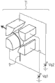
Figure 1A is the schematic diagram representing according to time-of-flight mass spectrometer of the present invention.
Figure 1B is the analog result representing according to the primary ions track of the first embodiment.
Fig. 1 C is the analog result representing according near the secondary ion track of of the measuring object 2 of the first embodiment.
Fig. 1 D is the analog result representing according to the secondary ion track of the first embodiment.
Fig. 1 E is the schematic diagram that represents the secondary ion track in the embodiment pattern of sweep type.
Fig. 2 A is the diagram representing according to the time-of-flight mass spectrometer of the second embodiment.
Fig. 2 B is the analog result representing according to the primary ions trace simulation result of the second embodiment.
Fig. 2 C is the analog result representing according to the secondary ion trace simulation result of the second embodiment.
Fig. 3 A is the schematic diagram representing according to the deflection unit of the first and second embodiment.
Fig. 3 B is the schematic diagram that represents to have with the deflection unit of the reference electrode in aperture.
Fig. 3 C is the schematic diagram that represents the deflection unit of field type.
Fig. 3 D is the schematic diagram that represents the deflection unit of quadripolar electric field type.
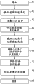
Fig. 4 A is the flow chart that represents projection type imaging mass spectral analysis.
Fig. 4 B is the flow chart that represents sweep type mass spectral analysis.
Fig. 5 is the schematic diagram that represents projection type imaging mass spectral analysis.
Fig. 6 A is the schematic diagram representing according to the deflection unit of the 3rd embodiment.
Fig. 6 B is the analog result representing according to the primary ions trace simulation result of the 3rd embodiment.
Fig. 6 C is the analog result representing according to the secondary ion track of the 3rd embodiment.
Fig. 6 D is the analog result of the primary ions trace simulation result while representing that deflection unit is 45 ° of types.
Fig. 6 E represents that aperture is modified to the schematic diagram of the deflection unit of slit.
Fig. 6 F is the schematic diagram that represents the deflection unit that uses mesh.
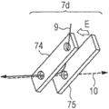
Fig. 7 A is the schematic diagram representing according to the deflection unit of the 4th embodiment.
Fig. 7 B is the analog result representing according to the primary ions trace simulation result of the 4th embodiment.
Fig. 7 C is the analog result representing according to the secondary ion track of the 4th embodiment.
Fig. 8 A is the schematic diagram representing according to the deflection unit of the 5th embodiment.
Fig. 8 B is the analog result representing according to the primary ions trace simulation result of the 5th embodiment.
Fig. 8 C is the analog result representing according to the secondary ion trace simulation result of the 5th embodiment.
Embodiment
The present invention relates to irradiate measuring object therefrom to produce secondary ion and to detect the mass spectrometer of secondary ion by primary ions.Figure 1A represents the mass spectrometric embodiment pattern of flight time type according to the present invention.Although exemplarily disclose flight time type mass spectrometer here, specification is not scope of the present invention will be limited to flight time type.The present invention also can be applied to other type, such as the mass spectrometer of ion trap type or four polar forms.
Time-of-flight mass spectrometer have produce primary ions primary ion source 1, arrange above the platform 2 of measuring object, with primary ions irradiate the primary ions optical system 12 of measuring object, as the secondary ion optical system 4 of the convergence unit to detector guiding secondary ion, as detector 5 and unshowned gas extraction system and the data handling system of the detecting unit for detection of secondary ion.Primary ions optical system 12 has deflection primary ions and makes primary ions deflection unit 7 crossing with the flight space of secondary ion in flight course.Secondary ion optical system 4 has as causing from the secondary ion flight of measuring object transmitting and secondary ion being guided into extraction/projecting electrode 3 and the deflection unit 7 of the guidance unit of detecting unit.By this configuration, the part between deflection unit 7 and measuring object 2 is as the ion-optic system of primary ions and secondary ion.Can be preferably set up in the mode of the flight space that surrounds secondary ion as the extraction/projecting electrode 3 of guidance unit, make preferably to realize primary ions and be deflected from flight space, to fly to the configuration in flight space by deflection unit.Here, the flight space of secondary ion refers to the space that the secondary ion between measuring object and detecting unit flies over therein.
The track of the primary ions producing from primary ion source 1 is deflected (Figure 1B) by the deflection unit 7 of the ion optical axis setting along secondary ion optical system 8.Deflection unit 7 is arranged between measuring object 2 and detector 5.It can be arranged between extraction/projecting electrode 3 and detector 5 as shown in Figure 1A like that, or being arranged on like that between the electrode group for assembling secondary ion as shown in Figure 2 A.
Deflection unit 7 spatially with the path overlap of secondary ion, and it has at least the structure (Fig. 1 C) that allows during not through deflection unit 7 secondary ion to see through (, switch) with limited probability in primary ions between beam.
In deflection unit 7, two or more electrodes are set up in the mode that secondary ion optical system is arranged on therebetween, the track that makes primary ions by the electric field that produces between at least one pair of electrode by electrostatic deflection, described at least one pair of electrode is faced mutually, is wherein provided with secondary ion optical system (Fig. 3 A, Fig. 3 B and Fig. 3 D).Although above-mentioned electrostatic deflection unit has high service speed and is therefore conducive to carry out secondary ion mass spectroscopy analysis, also can use the system of using like that Lorentz force deflection primary ions track by applying magnetic field as shown in Figure 3 C.
When use has while allowing secondary ion through the electrode of single or multiple apertures wherein or mesh, the through deflection unit (Fig. 6 A, Fig. 6 D, Fig. 6 E, Fig. 6 F, Fig. 7 A and Fig. 8 A) that does not form secondary ion optical axis between electrode can be set.
By above-mentioned configuration, in the time that deflection unit 7 operates by applying of predetermined voltage, make primary ions be incident in measuring object.Simultaneously, after primary ions incident, voltage, from for the voltage that deflection unit 7 operates is changed so that deflection unit 7 enters non-operating state, makes it possible to detect secondary ion by detector 5 by secondary ion optical system 4 in the situation that of obstructed overshoot unit 7 secondary interference ion.As used herein, " voltage from for the voltage that deflection unit 7 operates is changed " comprises that the voltage applying to deflection unit becomes 0.
In primary ions is irradiated, one group of primary ions that can preferably incident pulse mode is pulsed ionizing beam, and the beam with the diameter that is more than or equal to 10 μ m and is less than or equal to 100mm can preferably be incident on the emitting surface of measuring object.
Note, can guide secondary ion to secondary ion detector 5 in the case of not changing the voltage applying to deflection unit 7, can in the situation that not making deflection unit 7 enter non-operating state, realize according to time-of-flight mass spectrometer of the present invention.
Although the ion optical axis 6 of primary ions can be by coaxial setting (Figure 1A) with the ion optical axis 8 of secondary ion in the time making primary ions be incident in measuring object 2, but the always strict coaxial ion optical axis that arranges, and can be set to mutual skew according to object and the situation axle measured.Especially, when axle is during by coaxial setting, easily make primary ions be normally incident on the surface of measuring object 2, thus, even exist convex-concave, also can irradiate whole surface by primary ions on the surface of measuring object 2.Meanwhile, because the ion optical axis of secondary ion optical system 4 also can be vertical with the surface of measuring object 2, therefore can effectively extract secondary ion along the normal to a surface direction of measuring object 2.
As a result, the difference between the lip-deep species distribution of the distribution of the ion of launching from measuring object 2 and measuring object improves, and improves thus certainty of measurement.
Even it should be noted that when the ion optical axis 6 of primary ions and secondary ion optical axis 8 incomplete when overlapped, also can realize the surperficial vertical incidence of primary ions to measuring object 2, and can irradiate by primary ions the whole surface of convex-concave measuring object 2.
The secondary ion of launching from measuring object 2 is accelerated by extraction/projecting electrode 3 of the part as secondary ion optical system 4, and, when needed by after accelerating electrode 11 is accelerated again, arrive detector 5 detected thus further.Because the time by transmitting secondary ion measures secondary ion and passes the needed time of secondary ion optical system 4 (flight time) with difference between time of secondary ion being detected, therefore, the quality (m/z) of the tachometric survey secondary ion based on secondary ion.
Preferably, detector 5 has the area sensor that detects secondary ion, easily to obtain secondary ion quality image.
In the time that secondary ion optical system 4 has the characteristic forming from the distributed image of the secondary ion of the surface emitting of measuring object 2, acquisition can be measured the favorable characteristics (so-called projection type) of the species distribution in the region of irradiating by primary ions immediately.
And, secondary ion optical system 4 can more preferably have the configuration as system, and this system has the image formation unit as control unit of computer and the display unit such as liquid crystal display of demonstration two dimensional image that form two dimensional image such as the quality information based on obtaining by area sensor.
And, can form two dimensional image is overlapped in to the doubling of the image unit on another two dimensional image of optical imagery as the computer of control unit.
And, mass spectrometric analysis method of the present invention is for by making primary ions flight and irradiating measuring object 2 to be detected the method for the secondary ion of launching from measuring object 2 by detector by primary ions, and the method comprises deflection primary ions so that its step of passing between measuring object and detector in flight course and secondary ion is guided into the step of detector.
Shown in Fig. 5 be schematically illustrated by by projection type secondary ion optical system 4 from measuring object 2 extract secondary ion as image to carry out the diagram of the method for imaging mass spectral analysis according to the flight time (t1~t3).
Simultaneously, in the time that secondary ion optical system 4 is not projection type (Fig. 1 E), can by execution be scanned primary ions bundle irradiate fine region mass spectral analysis and according to the species distribution (sweep type) of the outcome measurement measuring object 2 of the position of fine region and analytical data of mass spectrum.
The first embodiment
The mass spectrometric analysis method of the use time-of-flight mass spectrometer (Figure 1A) of the first embodiment is described with reference to Fig. 4 A.
In the time starting to measure (A1), apply voltage (A2) to parallel-plate-type deflection unit 7a, and, launch primary ions in the mode of pulse from primary ion source 1.After the track of primary ions is deflected by deflection unit 7a, (after incident direction changes), makes primary ions be incident in (A3) on measuring object 2.In the present embodiment, the deflection unit 7 of Figure 1A has the structure of the deflection unit 7a of Fig. 3 A.
In Figure 1B, represent the primary ions track 9 based on Ion optics simulation.Primary ions is the cation with the acceleration energy of 10keV, and primary ions bundle is deflected by the electric field producing between the parallel-plate-type electrode at deflection unit 7a.
The deflection unit 7a of the present embodiment is that reference electrode 71 make secondary ion optical system relative to main deflection electrode 70 is arranged between them described in main deflection electrode 70, reference electrode 71(by three or more electrodes) and auxiliary electrode 72 form.At least one pair of electrode that forms reference electrode 71 and auxiliary electrode 72 is mutually opposed, makes primary ions optical system be arranged on (Fig. 3 A) between them.In Figure 1B, the voltage applying to main deflection electrode 70, reference electrode 71 and auxiliary electrode 72 is respectively 10kV, 0V and 500V.
As substituting of deflection unit 7a, can use to have to be with to be useful on to allow the deflection unit 7b(Fig. 3 B of primary ions through the reference electrode 73 in aperture wherein).Deflection unit 7b is because its simple structure has the convenience of manufacture and cost advantage.But it is because it can easily adjust position and the angle of primary ions to the incident of measuring object 2 by adjusting the voltage applying to auxiliary electrode 72 in deflection unit 7a that deflection unit 7a is used in the present embodiment.
As an alternative, as substituting of deflection unit 7a, can use quadripolar electric field type deflection unit 7i(Fig. 3 D).By applying different voltage Vq1 and Vq2, deflection unit 7i can deflection from the primary ions of the direction flight vertical with secondary ion optical axis 8, make the primary ions can be crossing with the flight space of secondary ion.
As the replacement scheme of above-mentioned electric field type deflection unit, can use field type deflection unit 7c.
In addition, in order to adjust primary ions incoming position, can be provided for along electrode or the magnetic field applying unit of the track of the vertical direction deflection primary ions of the paper in Figure 1B.
Primary ions optical axis 6 is not parallel with secondary ion optical axis 8 between deflection unit 7a and primary ion source 1, and at least, between measuring object 2 and extraction/projecting electrode 3, primary ions optical axis 6 and secondary ion optical axis 8 be coaxial (Figure 1B, Fig. 1 C) mutually.
Primary ions optical axis 6 when making primary ions be incident in measuring object 2 is vertical with the surface of measuring object or have the angle that approaches vertical angle, therefore, realizes the surperficial protuberance of primary ions to measuring object 2 and the irradiation of recess.
In the time completing primary ions irradiation (A3), deflection unit 7a enters non-operating state (A4), and, apply voltage (A5) to secondary ion optical system.Here, in the time making deflection unit 7a there is the electromotive force identical with exiting side extraction/projecting electrode 33, the track of secondary ion is not exerted one's influence, and secondary ion is realized mobile uniformly when through deflection unit 7a.
In the situation that can be in the time applying voltage to secondary ion optical system irradiating measuring object 2 by primary ions, the step of A5 can be applied continuously to secondary ion optical system 4 voltage and be substituted.Accelerated by extraction/projecting electrode 3 from the secondary ion of measuring object transmitting, to arrive detector 5 by secondary ion optical system 4.In the present embodiment, detector 5 is for detecting the in-position of secondary ion on detector 5 and the area sensor of detection time (A6).In the present embodiment, then accelerating electrode 11 be omitted.
In the present embodiment, be set to forming the voltage that the electrode of extractions/projecting electrode 3 applies, the position that makes to launch secondary ion on measuring object 2 with secondary ion in the in-position at detector 5 places mutual corresponding (, to obtain projection).
Shown in Fig. 1 C is to main apply-5kV of extraction/projecting electrode 31, to assembling extraction/projecting electrode 32 apply-0.7kV, to apply-2.5kV of exiting side extraction/projecting electrode 33 and to the analog result of the positive secondary ion track in the situation of apply-2.5kV of detector 5.Three electrodes are the aperture type electrostatic lens with mutually coaxial circular aperture.
Assemble secondary ion by extraction/projecting electrode 3, and, the image (Fig. 1 C, Fig. 1 D) of the secondary ion that formation is launched from measuring object 2 in detector 5.
Extraction/projecting electrode 3 can be the aperture type electrostatic lens being formed by two electrodes.Above-mentioned with three or more electrodes is preferred.
In the present embodiment, as shown in Fig. 1 D, assembling the interarea 20 that forms secondary ion optical system between extraction/projecting electrode 32 and exiting side extraction/projecting electrode 33.Can adjust by changing the voltage applying to main extraction/projecting electrode 31, convergence extraction/projecting electrode 32 and exiting side extraction/projecting electrode 33 etc. the position of interarea 20.
In the present embodiment, deflection unit 7a, between interarea and detector 5, therefore, can realize the long flying distance of secondary ion in even mobile status.This is due to the following facts: because exiting side extraction projecting electrode 33 is identical with the electromotive force of detector 5, therefore, do not increase or reduce through the speed of extracting projecting electrode 3 secondary ion afterwards.And because flight time t in the time increasing flying distance increases, therefore, mass resolution is improved.
And, as the formula (1), by the distance L from interarea 20 to detector 52 being lengthened into the distance L 1 than from interarea 20 to measuring object 2 is long, can advantageously increase multiplying power M.
M=L2/L1…(1)
In Fig. 1 C, for simplifying the reason of explaining, secondary ion track is that 30mm and L2 simulated under 300mm condition at L1, here, and the secondary ion image (Fig. 1 D) of the projection measuring object 2 on detector 5 of the multiplying power with × 10.
The trickleer structure that can watch measuring object by increasing multiplying power M.
For example, in the time becoming mode that 10mm and L2 become 1000~3000mm with L1 electrode is set, can obtain × 100 to × 300 multiplying power.In the time that the position probing resolution of detector 5 is 10 μ m, can realize the imaging mass spectral analysis of the spatial resolution with 0.03~0.1 μ m.
In the present embodiment, be applied to convergence extraction/projecting electrode 32(second electrode adjacent with the main extraction/projecting electrode that approaches most measuring object (the first electrode) 31 than the little accelerating voltage of accelerating voltage applying to main extraction/projecting electrode 31), and, be applied to the exiting side extraction/projecting electrode (third electrode) 33 adjacent with assembling extraction/projecting electrode 32 than the large accelerating voltage of accelerating voltage applying to convergence extraction/projecting electrode 32.
As a result, near the strong extraction electric field of generation measuring object 2, to improve the detection efficiency of secondary ion.And the focal length that extracts electrode 3 due to projection lengthens, therefore obtain the characteristic that increases multiplying power and improve mass resolution.
And, about the secondary ion with negative electrical charge, can carry out mass spectral analysis by the polarity that reverses the electromotive force applying to secondary ion optical system 4.
Can arrive the needed time of detector 5 by the time measurement secondary ion when making primary ions be incident in measuring object 2 and measure the flight time t(A3 of secondary ion).In the present embodiment, the voltage that applies that extracts electrode 33 due to exiting side is substantially equal to secondary ion and is incident in the accelerating voltage V on detector 5
ext, therefore, can pass through approximate expression (2) according to the mass spectral analysis (A7) of the flight time t of secondary ion and flying distance L execution secondary ion.In formula (2), " e " representative element electric charge (elementary charge).
m/z=2eV
ext(t/L)
2…(2)
By making the coordinate on detector 5 relevant to mass spectrometry results, the mass spectral analysis image (Fig. 5) (A8, A9) of each in the quality (mz) of acquisition secondary ion.
And by such step (A10) and repeating step A10~A7 of determining primary ions irradiation position of increasing as shown in Figure 4 B, mass spectrometer according to the present invention can be used as sweep type mass spectrometer.
The second embodiment
To the mass spectrometric analysis method of use time-of-flight mass spectrometer (Fig. 2 A~2C) of the second embodiment be described based on Fig. 4 A.
Starting to measure (A1) afterwards, from the deflection (variation of incident direction) of the track of primary ions to inciding measuring object 2(A3) flow process identical with the first embodiment.In the present embodiment, the deflection unit 7 of Figure 1A has the structure of the deflection unit 7a of Fig. 3 A.
Shown in Fig. 2 B is the Ion optics simulation result of primary ions track 9.
Primary ions optical axis 6 and secondary ion the optical axis 8 at least surface of the primary ions optical axis 6 at measuring object 2 and when extracting feature coaxial between electrode 35 and making primary ions be incident on measuring object 2 and measuring object 2 are vertical or have a feature identical with the first embodiment (Fig. 2 A) of the angle that approaches vertical angle.
In the present embodiment, extract between electrode 35 and convergence electrode 37 because deflection unit 7a is arranged on, therefore, compared with the first embodiment, can more approach measuring object 2 ground deflection unit 7a is set.As a result, can shorten the operating distance of primary ion source 1 to measuring object 2.
In the time controlling the size of primary ions bundle, the minimizing of operating distance is favourable.
In the time completing primary ions irradiation (A3), it is identical with the electromotive force of target 36 that the electromotive force of deflection unit 7a becomes, to obtain non-operating state (A4).Identical with the first embodiment for executing alive timing to secondary ion optical system 4.
The secondary ion of launching from measuring object 2 is accelerated by extraction electrode 35 and target 36, is converged, and then arrives detector 5 by convergence electrode 37.Because detector 5 is in-position and the area sensor of detection time (A6) that detects secondary ion, therefore, identical with the situation of the first embodiment, detector 5 is as projection type time-of-flight mass spectrometer.
Shown in Fig. 2 C is to extracting electrode 35 apply-150V, to apply-3.5kV of target 36, to apply-9.5kV of convergence electrode 37 and to the analog result of the positive secondary ion track in the present embodiment in the situation of apply-9.5kV of detector 5.Three electrodes are coaxial cylinder electrostatic lens.Although track is different from the first embodiment, secondary ion is converged by convergence electrode 37, and, the image of the secondary ion that formation is launched from measuring object 2 in quadratic detector 5.
The first interarea 21 forms by extracting electrode 35 and target 36, and, form second interarea 22(Fig. 2 C by target 36 and convergence electrode 37).The second interarea is between deflection unit 7a and secondary ion detector 5.Because all easily move the position of two interareas, therefore, be conducive to the adjustment of multiplying power.In addition, can increase interarea and form the structure with two or more interareas by increasing electrode, and, determine the position of interarea according to the position of electrode and the voltage that applies.
Due to apply-9.5kV of detector 5 to increase the acceleration energy of secondary ion while being incident in detector 5, therefore, under the condition of Fig. 2 C, in the situation that not using again accelerating electrode, effectively detect secondary ion.
Due to can be with the first embodiment similarly based on making primary ions be incident in measuring object 2(A3) the flight time t of time measurement secondary ion, therefore, can carry out according to the flying distance L of the kinetic energy of secondary ion and secondary ion the mass spectral analysis of secondary ion.
Due to as in the present embodiment through the secondary ion after interarea 21 than to extracting the large accelerating voltage of voltage that electrode 35 applies, to be applied to as described in target 36(target 36 adjacent with the extraction electrode 35 that approaches most measuring object 2) time approach parallel-beam, therefore, the distance between the first interarea 21 and the second interarea 22 can be set neatly.Especially, by making the distance L 3 between the first interarea 21 and the second interarea 22 remain the distance L 5 between distance L 4 and the second interarea 22 and the detector 5 being greater than fully between the first interarea 21 and measuring object 2, can carry out mass spectral analysis (A7) in the mode being similar to by the L with L3 substituted (2).
Meanwhile, when from the starting to the distance of detector 5 during fully than distance from measuring object 2 to convergence electrode 37 of convergence electrode 37, can be by the V of the electromotive force substituted (2) with convergence electrode 37
extcarry out the mass spectral analysis (A7) of secondary ion in the mode being similar to.
On the other hand, when the distance from convergence electrode 37 to detector 5 fully than the distance from measuring object 2 to convergence electrode 37 in short-term, the V of the electromotive force substituted (2) of available extraction electrode 36
ext.
Coordinate from detector 5 is identical with the first embodiment with the feature (A8) that mass spectrometry results obtains mass spectral analysis image (Fig. 5).
The 3rd embodiment
By the mass spectrometric analysis method of the use time-of-flight mass spectrometer (Fig. 6 A~6F) of description the 3rd embodiment.
In the present embodiment, although as the alternative Fig. 6 of the setting A of the deflection unit 7a of the first embodiment run through type deflection unit 7d, feature, the primary ions energy and the voltage applying to extraction/projecting electrode 3 etc. that make primary ions after running through type deflection unit 7d deflection, be incident in measuring object 2 at its track are identical with the first embodiment.
Shown in Fig. 6 B is the Ion optics simulation result of primary ions track 9.
In the present embodiment, at least the surface of the primary ions optical axis 6 at measuring object 2 and when extracting feature (Fig. 6 B) coaxial between electrode 3 and making primary ions be incident on measuring object 2 and measuring object 2 is vertical or to have the feature of the angle that approaches vertical angle identical with the first embodiment for primary ions optical axis 6 and secondary ion optical axis 8.
In Fig. 6 B, the electrode 74 with the aperture for seeing through primary ions/secondary ion is parallel to each other substantially with the electrode 75 with the aperture for seeing through secondary ion, and the angle θ forming with secondary ion optical axis 8 is 30 °.Ran through type deflection unit 7d when upper when primary ions incides, apply the voltage of 0V to electrode 74, and apply the voltage of 3.9kV to electrode 75.Distance between electrode is 9mm.Angle θ needn't be always 30 °.But for will and running through the primary ions track 9 between type deflection unit 7d at the ion source 1 of secondary ion optical system 4 outsides formation, angle θ can be preferably large satisfactorily.
In the time that angle θ is set as 30 ° as in this embodiment, even in the time that primary ions track 9 has dispersion along angle direction, also can irradiate measuring object 2 by the primary ions focusing on.Owing to increasing primary ions current density by this feature, therefore, certainty of measurement is improved.And, in the time adopting this feature for sweep type mass spectrometer, can improve spatial resolution.
As shown in Figure 6 D, angle θ can be 45 degree.By this configuration, because primary ions track 9 focuses near the aperture of electrode 74 with the aperture for seeing through primary ions/secondary ion to reduce the collision in primary ions and aperture, be therefore expected to realize noise reduction.Apply the voltage of 0V to the electrode 74 with the aperture for seeing through primary ions/secondary ion, and, to thering is the voltage that applies 10.1kV for the electrode 75 in the aperture through secondary ion.Distance between electrode is 10mm.
Because primary ions track 9 continuously changes with respect to the convergence of angle θ, therefore, primary ions track 9 is by making angle θ become 45 ° and gradually become the situation of Fig. 6 D from the situation of Fig. 6 B from 30 °.Because the difference between two angle θ is in approximately 30% scope, therefore, can in the scope of the angle θ of 20 °~60 °, uses and run through type deflection unit 7d by allowing the gradually changing of convergence of primary ions track.
Aperture can need not to be the aperture with the shape that runs through the aperture in type deflection unit 7d that is arranged on Fig. 6 A, and, can use that Fig. 6 E's run through the having for allowing ion to pass the electrode 80 of slit wherein of type deflection unit 7e.
And as shown in Fig. 6 F, deflection unit 7 can be the mesh type deflection unit 7f that uses two mesh electrodes 79.Due to mesh, therefore deflection unit 7f allows to see through primary ions and secondary ion in the situation that aperture not being set, and therefore, the interference of the deflecting electric field being caused by aperture is in addition suppressed to obtain the little advantage of edge effect (fringing effect).
When complete primary ions irradiate time, whole deflection unit 7(comprises 7d, 7e and 7f) electromotive force become the electromotive force identical with exiting side extraction/projecting electrode 33, and, apply voltage to secondary ion optical system 4.
The secondary ion of launching from measuring object 2 is converged and is then arrived detector 5 by extraction/projecting electrode 3, and, identical with the situation of the first embodiment, detector 5 is as the area sensor of time-of-flight mass spectrometer, and this makes it possible to obtain mass spectral analysis image (Fig. 5).
Shown in Fig. 6 C is to main apply-5kV of extraction/projecting electrode 31, to assembling extraction/projecting electrode 32 apply-0.7kV, to apply-2.5kV of exiting side extraction/projecting electrode 33 and to the analog result of the positive secondary ion track in the situation of apply-2.5kV of detector 5.
Identical with the situation of the first embodiment, also can be used as sweep type mass spectrometer according to mass spectrometer of the present invention.And identical with the second embodiment, as substituting of aperture type electrostatic lens, ion-optic system can be formed by coaxial cylinder electrostatic lens.
The 4th embodiment
By the mass spectrometric analysis method of the use time-of-flight mass spectrometer (Fig. 7 A~7C) of description the 4th embodiment.
Run through type deflection unit 7d to substitute except use runs through type deflection unit 7g, the present embodiment is identical with the 3rd embodiment.
Shown in Fig. 7 B is the Ion optics simulation result of the primary ions track 9 of the present embodiment.At least, between measuring object 2 and extraction electrode 3, the position relationship between primary ions optical axis 6, secondary ion optical axis 8 and measuring object 2 is identical with the 3rd embodiment.
In Fig. 7 B, cylinder electrode 76 and to have the axle of cylinder electrode 77 in the aperture for seeing through secondary ion mutually coaxial, and, between two electrodes, form electric sector.The central angle of electric sector is 90 °.Apply the voltage of 0V to electrode 76, and apply the voltage of 8.1kV to electrode 77.The radius of electrode 76 is 14mm, and the radius of electrode 77 is 23mm.Distance between electrode is 9mm.Central angle needn't be always 90 °.But for being positioned at the ion source 1 of secondary ion optical system 4 outsides and running through the primary ions track 9 between type deflection unit 7g, central angle can be preferably large satisfactorily.
In the time that such angle is as shown in Figure 7 B 90 °, even when primary ions track 9 is during by spatial dispersion, the primary ions that measuring object 2 is also advantageously focused is irradiated.And the central angle of 127 ° is conducive to assemble primary ions.For the reason identical with the 3rd embodiment, central angle can be 60~180 °.
As substituting of two cylinder electrodes, can use a pair of concentric spherical electrode.
In the time completing primary ions irradiation, the whole electromotive force that runs through type deflection unit 7g becomes the electromotive force identical with exiting side extraction/projecting electrode 33, and, apply voltage to secondary ion optical system 4, make, identical with the situation of the first embodiment, detector 5 is as the area sensor of projection type time-of-flight mass spectrometer.
Shown in Fig. 7 C be to main apply-5kV of extraction/projecting electrode 31, extract electrode 32 apply-0.7kV to assembling, to apply-2.5kV of exiting side extraction/projecting electrode 33 and to the analog result of the positive secondary ion track in the present embodiment in the situation of apply-2.5kV of detector 5.
Identical with the situation of the first embodiment, also can be used as sweep type mass spectrometer according to mass spectrometer of the present invention.Identical with the 3rd embodiment, cylinder electrode 76 can be mesh electrodes with the cylinder electrode 77 with the aperture for seeing through secondary ion.Identical with the second embodiment, as substituting of aperture type electrostatic lens, ion-optic system can be formed by coaxial cylinder electrostatic lens.
The 5th embodiment
By the mass spectrometric analysis method of the use time-of-flight mass spectrometer (Fig. 8 A~8C) of description the 5th embodiment.
Except having the deflection unit 7h shown in Fig. 8 A to substitute deflection unit 7d, the present embodiment is identical with the 3rd embodiment.
Shown in Fig. 8 B is the Ion optics simulation result of primary ions track 9.At least, between measuring object 2 and extraction electrode 3, the position relationship between primary ions optical axis 6, secondary ion optical axis 8 and measuring object 2 is identical with the 3rd embodiment.
Run through type deflection unit the 7h electrode with aperture 78 being substantially parallel to each other by pair of electrodes and the electrode 75 with the aperture for seeing through secondary ion and form, and, be 45 ° with respect to the angle θ of secondary ion optical axis 8.In the time that primary ions incides deflection unit 7h, apply the voltage of 0V to electrode 78, and, apply the voltage of 6.2kV to electrode 75.Distance between electrode is 10mm.Inclination angle theta needs not to be 45 °.The present embodiment tool has the following advantages: only arrange one for seeing through the aperture of primary ions to realize simple structure, and, primary ions is incident in run through the degree of freedom of direction of type deflection unit 7h high.
In the time completing primary ions irradiation, the electromotive force of whole deflection unit 7 becomes the electromotive force identical with exiting side extraction/projecting electrode 33, and, apply voltage to secondary ion optical system 4, make, identical with the situation of the first embodiment, detector 5 is as the area sensor of projection type time-of-flight mass spectrometer.
Shown in Fig. 8 C be to main apply-5kV of extraction/projecting electrode 31, extract electrode 32 apply-0.7kV to assembling, to apply-2.5kV of exiting side extraction/projecting electrode 33 and to the analog result of the positive secondary ion track in the present embodiment in the situation of apply-2.5kV of detector 5.
Identical with the situation of the first embodiment, also can be used as sweep type mass spectrometer according to mass spectrometer of the present invention.Identical with the 3rd embodiment, having the electrode 78 in aperture and have for the electrode 75 in the aperture through secondary ion can be mesh electrodes.Identical with the second embodiment, as substituting of aperture type electrostatic lens, ion-optic system can be formed by coaxial cylinder electrostatic lens.
Although the present invention has been described with reference to exemplary embodiment, has should be understood that and the invention is not restricted to disclosed exemplary embodiment.The scope of claims should be endowed the 26S Proteasome Structure and Function of the widest explanation to comprise all such modifications and to be equal to.
The application requires the Japanese patent application No.2011-225509 submitting on October 13rd, 2011 and the rights and interests of Japanese patent application No.2012-223084 of submitting on October 5th, 2012, is incorporated to its full content at this by application.
Claims (31)
1. a mass spectrometer, comprising:
Platform, described platform is for placing measuring object thereon;
Primary ions generator, described primary ions generator is configured to produce the primary ions that will fly;
Primary ions optical system, described primary ions optical system is configured to primary ions to guide measuring object into and irradiate measuring object by primary ions;
Detecting unit, described detecting unit is configured to detect the secondary ion from measuring object transmitting; With
Secondary ion optical system, described secondary ion optical system is configured to guide secondary ion into detecting unit,
Wherein, primary ions optical system comprises deflection unit, and described deflection unit is configured to make primary ions mode deflection primary ions crossing with the flight space of secondary ion in flight course.
2. mass spectrometer according to claim 1,
Wherein, primary ions is to make primary ions fly to the mode in described flight space from the flight space extrinsic deflection of secondary ion by deflection unit.
3. mass spectrometer according to claim 1 and 2,
Wherein, at least, in the time making primary ions be incident on measuring object, the ion optical axis of the ion optical axis of primary ions optical system and secondary ion optical system is coaxial.
4. according to the mass spectrometer described in any one in claim 1~3,
Wherein, deflection unit is by the track of electric deflection primary ions.
5. mass spectrometer according to claim 4,
Wherein, deflection unit comprises two or more electrodes.
6. mass spectrometer according to claim 5,
Wherein, at least one pair of electrode is mutually opposed, and the ion optical axis of secondary ion optical system is arranged between described at least one pair of electrode, and,
The electromotive force applying to the mutual opposed electrode of ion optical axis that is provided with secondary ion optical system is therebetween mutually different.
7. according to the mass spectrometer described in claim 5 or 6,
Wherein, at least one pair of electrode is mutually opposed, and the track of primary ions is arranged between described at least one pair of electrode, and,
The electromotive force applying to the mutual opposed electrode of track that is provided with primary ions optical system is therebetween mutually different.
8. according to the mass spectrometer described in any one in claim 5~7,
Wherein, one in described two or more electrodes has: the first electrode, and described the first electrode has at least one for allowing primary ions and secondary ion through aperture wherein; And, the second electrode.
9. mass spectrometer according to claim 8,
Wherein, the aperture of the first electrode only allows primary ions to pass wherein.
10. according to the mass spectrometer described in any one in claim 5~7,
Wherein, at least one ion optical axis with respect to secondary ion optical system in the first electrode and the second electrode tilts; And,
One in two or more electrodes has: the first electrode, and described the first electrode has at least one for allowing primary ions and secondary ion through aperture wherein; And, the second electrode, described the second electrode has for allowing secondary ion to pass aperture wherein.
11. mass spectrometers according to claim 10,
Wherein, the first electrode has multiple apertures, and, in the aperture of the first electrode, allow the first ion through wherein more than two apertures.
12. mass spectrometers according to claim 8,
Wherein, the first electrode and the second electrode form electric sector.
13. mass spectrometers according to claim 12,
Wherein, the central angle of described electric sector is 90 °~127 °.
14. according to the mass spectrometer described in any one in claim 5~7,
Wherein, at least one in the first electrode and the second electrode is mesh electrodes.
15. according to the mass spectrometer described in any one in claim 5~7,
Wherein, at least one in the aperture of the aperture of the first electrode and the second electrode is for allowing ion to pass slit wherein.
16. according to the mass spectrometer described in any one in claim 10,11,14 and 15,
Wherein, at least one ion optical axis with respect to secondary ion optical system in the first electrode and the second electrode tilts 30 °~45 °.
17. according to the mass spectrometer described in any one in claim 1~3,
Wherein, deflection unit is by the track of magnetic core logical circuit deflection primary ions.
18. according to the mass spectrometer described in any one in claim 1~17,
Wherein, described device is time-of-flight mass spectrometer.
19. according to the mass spectrometer described in any one in claim 1~18,
Wherein, primary ions generator is arranged on outside the ion optical axis of secondary ion optical system, and deflection unit is formed between measuring object and detecting unit.
20. mass spectrometers according to claim 19,
Wherein, deflection unit is arranged between the interarea and detecting unit of secondary ion optical system.
21. mass spectrometers according to claim 19,
Wherein, secondary ion optical system has two or more interareas, and,
Deflection unit is arranged between at least one and the measuring object in described interarea.
22. according to the mass spectrometer described in any one in claim 1~21,
Wherein, secondary ion optical system comprises guidance unit, and described guidance unit is configured to the secondary ion of detecting unit guiding transmitting; And,
Guidance unit is set up in the mode of the flight space of encirclement secondary ion.
23. mass spectrometers according to claim 22,
Wherein, secondary ion comprises two or more electrodes, and,
Be applied to the second electrode than the large accelerating voltage of voltage applying to the first electrode, described the second electrode is placed in the side different from measuring object of the first electrode.
24. mass spectrometers according to claim 22,
Wherein, secondary ion optical system comprises three or more electrodes, and,
The accelerating voltage less than the voltage that is applied to the first electrode is applied to the second electrode, described the second electrode is placed in the side different from measuring object of the first electrode, and, the accelerating voltage larger than the voltage that is applied to the second electrode is applied to third electrode, and described third electrode is placed in the side different from the first electrode of the second electrode.
25. according to the mass spectrometer described in any one in claim 1~24,
Wherein, primary ions generator irradiates the emitting surface of measuring object with the beam with the diameter that is more than or equal to 10 μ m and is less than or equal to 100mm.
26. according to the mass spectrometer described in any one in claim 1~25,
Wherein, secondary ion optical system is projection type.
27. mass spectrometers according to claim 26,
Wherein, detecting unit comprises the area sensor that is configured to detect secondary ion.
28. mass spectrometers according to claim 27, also comprise image formation unit, and described image formation unit is configured to form two dimensional image based on the quality information obtaining by area sensor.
29. mass spectrometers according to claim 28, also comprise display unit, and described display unit is configured to show two dimensional image.
30. mass spectrometers according to claim 29, also comprise doubling of the image unit, and described doubling of the image unit is configured to two dimensional image to be overlapped on another two dimensional image of optical imagery.
31. 1 kinds for making primary ions flight, irradiating measuring object and detects the mass spectrometric analysis method of the secondary ion of launching from measuring object by detector by primary ions, comprising:
With primary ions in the process of flight between measuring object and detector crossing mode deflection primary ions; And,
Guide secondary ion into detector.
Applications Claiming Priority (5)
| Application Number | Priority Date | Filing Date | Title |
|---|---|---|---|
| JP2011225509 | 2011-10-13 | ||
| JP2011-225509 | 2011-10-13 | ||
| JP2012-223084 | 2012-10-05 | ||
| JP2012223084A JP2013101918A (en) | 2011-10-13 | 2012-10-05 | Mass spectroscope |
| PCT/JP2012/076743 WO2013054937A1 (en) | 2011-10-13 | 2012-10-10 | Mass spectrometer |
Publications (1)
| Publication Number | Publication Date |
|---|---|
| CN103875057A true CN103875057A (en) | 2014-06-18 |
Family
ID=48081981
Family Applications (1)
| Application Number | Title | Priority Date | Filing Date |
|---|---|---|---|
| CN201280049341.7A Pending CN103875057A (en) | 2011-10-13 | 2012-10-10 | Mass spectrometer |
Country Status (6)
| Country | Link |
|---|---|
| US (1) | US8957392B2 (en) |
| EP (1) | EP2766917A4 (en) |
| JP (1) | JP2013101918A (en) |
| KR (1) | KR20140086992A (en) |
| CN (1) | CN103875057A (en) |
| WO (1) | WO2013054937A1 (en) |
Cited By (4)
| Publication number | Priority date | Publication date | Assignee | Title |
|---|---|---|---|---|
| CN106847659A (en) * | 2016-01-20 | 2017-06-13 | 加坦公司 | Use the electron energy loss spectrometer of direct detection sensor |
| CN109690307A (en) * | 2016-08-26 | 2019-04-26 | 株式会社岛津制作所 | Analytical data of mass spectrum processing unit is imaged |
| CN109923408A (en) * | 2016-11-18 | 2019-06-21 | 株式会社岛津制作所 | Ion analysis device |
| CN112309822A (en) * | 2020-09-29 | 2021-02-02 | 中国科学院地质与地球物理研究所 | Ion probe mass spectrometer and imaging method thereof |
Families Citing this family (6)
| Publication number | Priority date | Publication date | Assignee | Title |
|---|---|---|---|---|
| JP5885474B2 (en) | 2011-11-17 | 2016-03-15 | キヤノン株式会社 | Mass distribution analysis method and mass distribution analyzer |
| US8963081B2 (en) | 2013-03-06 | 2015-02-24 | Canon Kabushiki Kaisha | Mass selector, and ion gun, ion irradiation apparatus and mass microscope |
| JP6624790B2 (en) * | 2014-03-03 | 2019-12-25 | キヤノン株式会社 | Projection type charged particle optical system and imaging mass spectrometer |
| KR101634231B1 (en) | 2014-10-29 | 2016-06-29 | 한국표준과학연구원 | Particle Beam Mass Spectrometer and a method for Measuring a particle beam |
| JP6734874B2 (en) | 2015-05-26 | 2020-08-05 | パーキンエルマー・ヘルス・サイエンシーズ・インコーポレイテッドPerkinelmer Health Sciences, Inc. | Double bending ion guide and device using the same |
| US20230162962A1 (en) * | 2021-11-22 | 2023-05-25 | Perkinelmer Health Sciences, Inc. | Deflectors for ion beams and mass spectrometry systems comprising the same |
Citations (3)
| Publication number | Priority date | Publication date | Assignee | Title |
|---|---|---|---|---|
| US4889987A (en) * | 1986-06-04 | 1989-12-26 | Arch Development Corporation | Photo ion spectrometer |
| US5689112A (en) * | 1996-04-12 | 1997-11-18 | Enge; Harald A. | Apparatus for detection of surface contaminations on silicon wafers |
| US6002128A (en) * | 1995-07-04 | 1999-12-14 | Ionoptika, Ltd. | Sample analyzer |
Family Cites Families (11)
| Publication number | Priority date | Publication date | Assignee | Title |
|---|---|---|---|---|
| JPH0378951A (en) * | 1989-08-21 | 1991-04-04 | Jeol Ltd | Image photographing type ion micro-analyzer |
| JP2624854B2 (en) * | 1989-10-23 | 1997-06-25 | 株式会社日立製作所 | Secondary ion mass spectrometer |
| JP2926666B2 (en) * | 1991-05-13 | 1999-07-28 | 株式会社島津製作所 | Direct impact ion scattering spectrometer |
| JPH05129000A (en) * | 1991-11-07 | 1993-05-25 | Sumitomo Metal Mining Co Ltd | Ion gun for recti-collision ion scattering spectroscopic use |
| JP2919229B2 (en) * | 1993-07-07 | 1999-07-12 | 日本電気株式会社 | Focused ion beam processing method |
| JPH08153484A (en) * | 1994-11-30 | 1996-06-11 | Hitachi Ltd | Ion scattered front surface analyzing device |
| JP2001141673A (en) | 1999-11-16 | 2001-05-25 | Canon Inc | Time resolving type surface analyzing apparatus |
| GB0021902D0 (en) | 2000-09-06 | 2000-10-25 | Kratos Analytical Ltd | Ion optics system for TOF mass spectrometer |
| EP1388883B1 (en) * | 2002-08-07 | 2013-06-05 | Fei Company | Coaxial FIB-SEM column |
| JP5885474B2 (en) | 2011-11-17 | 2016-03-15 | キヤノン株式会社 | Mass distribution analysis method and mass distribution analyzer |
| JP2013239430A (en) * | 2012-04-16 | 2013-11-28 | Canon Inc | Flight time type mass spectrometry apparatus |
-
2012
- 2012-10-05 JP JP2012223084A patent/JP2013101918A/en not_active Withdrawn
- 2012-10-10 CN CN201280049341.7A patent/CN103875057A/en active Pending
- 2012-10-10 WO PCT/JP2012/076743 patent/WO2013054937A1/en active Application Filing
- 2012-10-10 EP EP12839905.2A patent/EP2766917A4/en not_active Withdrawn
- 2012-10-10 KR KR1020147011773A patent/KR20140086992A/en not_active Application Discontinuation
- 2012-10-10 US US14/349,892 patent/US8957392B2/en not_active Expired - Fee Related
Patent Citations (3)
| Publication number | Priority date | Publication date | Assignee | Title |
|---|---|---|---|---|
| US4889987A (en) * | 1986-06-04 | 1989-12-26 | Arch Development Corporation | Photo ion spectrometer |
| US6002128A (en) * | 1995-07-04 | 1999-12-14 | Ionoptika, Ltd. | Sample analyzer |
| US5689112A (en) * | 1996-04-12 | 1997-11-18 | Enge; Harald A. | Apparatus for detection of surface contaminations on silicon wafers |
Cited By (6)
| Publication number | Priority date | Publication date | Assignee | Title |
|---|---|---|---|---|
| CN106847659A (en) * | 2016-01-20 | 2017-06-13 | 加坦公司 | Use the electron energy loss spectrometer of direct detection sensor |
| CN106847659B (en) * | 2016-01-20 | 2019-10-11 | 加坦公司 | Use the electron energy loss spectrometer of direct detection sensor |
| CN109690307A (en) * | 2016-08-26 | 2019-04-26 | 株式会社岛津制作所 | Analytical data of mass spectrum processing unit is imaged |
| CN109923408A (en) * | 2016-11-18 | 2019-06-21 | 株式会社岛津制作所 | Ion analysis device |
| US10971349B2 (en) | 2016-11-18 | 2021-04-06 | Shimadzu Corporation | Ion analyzer |
| CN112309822A (en) * | 2020-09-29 | 2021-02-02 | 中国科学院地质与地球物理研究所 | Ion probe mass spectrometer and imaging method thereof |
Also Published As
| Publication number | Publication date |
|---|---|
| US20140239173A1 (en) | 2014-08-28 |
| JP2013101918A (en) | 2013-05-23 |
| KR20140086992A (en) | 2014-07-08 |
| WO2013054937A1 (en) | 2013-04-18 |
| EP2766917A4 (en) | 2015-07-22 |
| US8957392B2 (en) | 2015-02-17 |
| EP2766917A1 (en) | 2014-08-20 |
Similar Documents
| Publication | Publication Date | Title |
|---|---|---|
| CN103875057A (en) | Mass spectrometer | |
| US9543138B2 (en) | Ion optical system for MALDI-TOF mass spectrometer | |
| US5128543A (en) | Particle analyzer apparatus and method | |
| JP2006134893A (en) | Tandem mass spectrometry | |
| JPH07500448A (en) | Time-of-flight mass spectrometer with aperture that allows performance to be balanced between resolution and transfer efficiency | |
| US8759756B2 (en) | Time-of-flight mass spectrometer | |
| JPH09106780A (en) | Apparatus and method for surface analysis | |
| US20150155152A1 (en) | Mass spectrometry apparatus | |
| JP5885474B2 (en) | Mass distribution analysis method and mass distribution analyzer | |
| JPH0441462B2 (en) | ||
| JP5504969B2 (en) | Mass spectrometer | |
| CN110265282B (en) | Matrix-assisted laser desorption ionization time-of-flight mass spectrometer and sample detection method | |
| CN209843661U (en) | Matrix-assisted laser desorption ionization time-of-flight mass spectrometer | |
| US9754772B2 (en) | Charged particle image measuring device and imaging mass spectrometry apparatus | |
| JPH0450699B2 (en) | ||
| JP6750684B2 (en) | Ion analyzer | |
| JP6624790B2 (en) | Projection type charged particle optical system and imaging mass spectrometer | |
| JP2015519717A (en) | Compact time-of-flight mass spectrometer | |
| JP2018010766A (en) | Time-of-flight mass spectrometer | |
| JPS61114453A (en) | Charged particle ray device | |
| CN117690777A (en) | Multi-deflection branch ion guiding device and method based on electrostatic field and mass spectrometer | |
| JPH034433A (en) | Flight time type mass spectrometry device | |
| JP2017050279A (en) | Charged particle image measuring instrument and imaging mass spectrometer | |
| JPH03176957A (en) | Secondary ion analyzer | |
| JPS63213251A (en) | Time-of-flight type mass spectrograph |
Legal Events
| Date | Code | Title | Description |
|---|---|---|---|
| C06 | Publication | ||
| PB01 | Publication | ||
| C10 | Entry into substantive examination | ||
| SE01 | Entry into force of request for substantive examination | ||
| C02 | Deemed withdrawal of patent application after publication (patent law 2001) | ||
| WD01 | Invention patent application deemed withdrawn after publication |
Application publication date: 20140618 |