CN103485466A - Fully automatic side opening type ventilation clerestory - Google Patents
Fully automatic side opening type ventilation clerestory Download PDFInfo
- Publication number
- CN103485466A CN103485466A CN201210195768.XA CN201210195768A CN103485466A CN 103485466 A CN103485466 A CN 103485466A CN 201210195768 A CN201210195768 A CN 201210195768A CN 103485466 A CN103485466 A CN 103485466A
- Authority
- CN
- China
- Prior art keywords
- skeleton
- forms
- rotating shaft
- ventilation
- power set
- Prior art date
- Legal status (The legal status is an assumption and is not a legal conclusion. Google has not performed a legal analysis and makes no representation as to the accuracy of the status listed.)
- Pending
Links
Images

Abstract
The invention discloses a fully automatic side opening type ventilation clerestory, which comprises frameworks and framework pieces, wherein the whole bodies formed by fixedly connecting a plurality of frameworks and framework pieces are parallelly inserted on a roof purline at intervals, ventilation openings are formed in the two side walls of the frameworks, a motive power device and window bodies matched with the ventilation openings are also arranged in the frameworks, and the motive power device can drive the window bodies for covering the ventilation openings to close the ventilation openings or being disengaged from the ventilation openings to open the ventilation openings. The fully automatic side opening type ventilation clerestory has the advantages that the ventilation openings are formed in the side walls of the frameworks, the window bodies realize the opening and the closing of air openings in a lateral opening mode, products in factory buildings are enabled not to be polluted by rain, snow, sand and dust, the use is safe, the operation is convenient, and the structure is stable.
Description
Technical field
The present invention relates to a kind of dormer, particularly a kind of full-automatic laterally opened ventilation clerestory.
Background technology
Mainly realize ventilating by dormer in the factory building workshop, common dormer automatic ventilation structure is all that the ventilation opening of level is set on dormer top, by forms, cover and the ventilation opening that breaks away from this level is realized the ventilation opening open and close, but after running into sleety weather or dusty wind weather, the forms outside has sleet or sand and dust are piled up, when forms are opened, the sleet sand and dust of piling up will fall to and indoor indoor article be polluted, when forms are opened, outside sand and dust and sleet also can descend slowly and lightly and to indoor, indoor article be polluted.
Summary of the invention
In order to overcome above-mentioned defect, the invention provides a kind of full-automatic laterally opened ventilation clerestory, it is indoor that this full-automatic laterally opened ventilation clerestory can avoid the sleet sand and dust to drop to, and guarantees indoor cleaning, ventilates smooth and easy, uses safety.
The present invention for the technical scheme that solves its technical problem and adopt is: a kind of full-automatic laterally opened ventilation clerestory, comprise skeleton and matrix tablet, some skeletons and the matrix tablet whole parallel interval be connected to form that is connected is inserted on roof purline, described skeleton two side is provided with ventilation opening, also be provided with the forms and the power set that mate with ventilation opening in described skeleton, described power set can drive forms covering closure or break away from opens ventilation opening.
As a further improvement on the present invention, described power set can drive forms covering closure or break away from the structure of opening ventilation opening: take actual user to being benchmark, described forms are articulated in the both sides at skeleton top towards outdoor upper end, and forms be able to cover the ventilation opening of skeleton both sides, described power set can drive forms and rotate around jointed shaft.
As a further improvement on the present invention, described power set can drive forms: power set comprise motor, rotating shaft and first and second connecting rod, described motor is fixedly arranged on skeleton, the shaft circumference direction can rotational positioning on skeleton, rotating shaft is axially extended along the skeleton length direction, and motor power is exported to rotating shaft, and shaft circumference lateral wall and first connecting rod are connected, first connecting rod and second connecting rod are hinged, and second connecting rod and the forms inside wall of ventilation opening dorsad are hinged.
As a further improvement on the present invention, described shaft circumference direction can the structure of rotational positioning on skeleton be: the skeleton roof is provided with an axle bed, in described axle bed, is provided with bearing, and described rotating shaft is inserted in bearing.
As a further improvement on the present invention, the T shape frame structure of described skeleton for being formed by steel-pipe welding.
As a further improvement on the present invention, also be provided with gauge tap, switch is controlled machine operation.
The invention has the beneficial effects as follows: the present invention is by ventilation opening being arranged on the skeleton sidewall, and forms, by the laterally opened switching that realizes ventilation opening, guarantee that the interior product of factory building is not subject to the pollution of sleet and sand and dust, use safety, easy to operate, Stability Analysis of Structures.
The accompanying drawing explanation
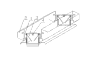
Fig. 1 is master's TV structure schematic diagram of the present invention;
Fig. 2 is perspective view of the present invention.
The specific embodiment
Embodiment: a kind of full-automatic laterally opened ventilation clerestory, comprise skeleton 1 and matrix tablet 2, some skeletons 1 and the matrix tablet 2 whole parallel interval be connected to form that is connected is inserted on roof purline, described skeleton 1 two side is provided with ventilation opening, also be provided with forms 3 and power set with the ventilation opening coupling in described skeleton 1, described power set can drive forms 3 covering closures or break away from opens ventilation opening, ventilation opening is arranged on skeleton 1 sidewall, the laterally opened opening and closing of dormer ventilation opening have been realized, effectively avoided sleet and sand and dust to drop to when forms 3 are opened indoor, pollute indoor article, even more severe sleet dusty wind weather, ventilation opening is opened and also can not caused the sleet dust storm to waft into indoor situation generation, when guaranteeing the indoor cleaning health, guarantee that room ventilation is smooth and easy, with fresh air.
Described power set can drive forms 3 covering closures or break away from the structure of opening ventilation opening: take actual user to being benchmark, described forms 3 are articulated in the both sides at skeleton 1 top towards outdoor upper end, and forms 3 be able to cover the ventilation opening of skeleton 1 both sides, described power set can drive forms 3 and rotate around jointed shaft.
Described power set can drive forms 3: power set comprise motor, rotating shaft 4 and first, two connecting rods 5, 6, described motor is fixedly arranged on skeleton 1, rotating shaft 4 circumferencial directions can rotational positioning on skeleton 1, rotating shaft 4 is axially extended along skeleton 1 length direction, motor power is exported to rotating shaft 4, rotating shaft 4 periphery walls and first connecting rod 5 are connected, first connecting rod 5 is hinged with second connecting rod 6, second connecting rod 6 and forms 3 inside wall of ventilation opening dorsad are hinged, this is simple in structure, it is convenient to control, save space, certainly rotating shaft 4 is except passing through first, two connecting rods 5, the mode of 6 linkages that form drives outside forms 3 rotations, can also realize by the mode of eccentric shaft, this is all the structure that those skilled in the art are easy to expect according to this patent.
Described rotating shaft 4 circumferencial directions can the structure of rotational positioning on skeleton 1 be: skeleton 1 roof is provided with an axle bed, in described axle bed, is provided with bearing, and described rotating shaft 4 is inserted in bearing, and rotating shaft 4 is rotated smooth and easy, prevents from using and freeing the wearing and tearing stuck phenomenon for a long time.
The T shape frame structure of described skeleton 1 for being formed by steel-pipe welding, this structure is applied widely, during actual the use, can select as required the steel pipe of different length to be welded, make the dormer that the aditus laryngis width is 500-1500mm, matrix tablet 2 adopts the moulding of galvanized sheet integrated punching, and centre connects with bolt.
Also be provided with gauge tap, switch is controlled machine operation, is convenient to the control that forms 3 open and close.
Claims (6)
1. a full-automatic laterally opened ventilation clerestory, comprise skeleton (1) and matrix tablet (2), some skeletons (1) and matrix tablet (2) the whole parallel interval be connected to form that is connected is inserted on roof purline, it is characterized in that: described skeleton (1) two side is provided with ventilation opening, also be provided with the forms (3) and the power set that mate with ventilation opening in described skeleton (1), described power set can drive forms (3) covering closure or break away from opens ventilation opening.
2. full-automatic laterally opened ventilation clerestory according to claim 1, it is characterized in that: described power set can drive forms (3) covering closure or break away from the structure of opening ventilation opening and be: take actual user to being benchmark, described forms (3) are articulated in the both sides at skeleton (1) top towards outdoor upper end, and forms (3) be able to cover the ventilation opening of skeleton (1) both sides, described power set can drive forms (3) and rotate around jointed shaft.
3. full-automatic laterally opened ventilation clerestory according to claim 2, it is characterized in that: described power set can drive forms (3) and around the structure of jointed shaft rotation be: power set comprise motor, rotating shaft (4) and first, two connecting rods (5, 6), described motor is fixedly arranged on skeleton (1), rotating shaft (4) circumferencial direction can rotational positioning on skeleton (1), rotating shaft (4) is axially extended along skeleton (1) length direction, motor power is exported to rotating shaft (4), rotating shaft (4) periphery wall and first connecting rod (5) are connected, first connecting rod (5) is hinged with second connecting rod (6), second connecting rod (6) and forms (3) inside wall of ventilation opening dorsad are hinged.
4. full-automatic laterally opened ventilation clerestory according to claim 3, it is characterized in that: described rotating shaft (4) circumferencial direction can the structure of rotational positioning on skeleton (1) be: skeleton (1) roof is provided with an axle bed, in described axle bed, is provided with bearing,
Described rotating shaft (4) is inserted in bearing.
5. full-automatic laterally opened ventilation clerestory according to claim 1, is characterized in that: the T shape frame structure of described skeleton (1) for being formed by steel-pipe welding.
6. full-automatic laterally opened ventilation clerestory according to claim 1, is characterized in that: also be provided with gauge tap, switch control machine operation.
Priority Applications (1)
| Application Number | Priority Date | Filing Date | Title |
|---|---|---|---|
| CN201210195768.XA CN103485466A (en) | 2012-06-14 | 2012-06-14 | Fully automatic side opening type ventilation clerestory |
Applications Claiming Priority (1)
| Application Number | Priority Date | Filing Date | Title |
|---|---|---|---|
| CN201210195768.XA CN103485466A (en) | 2012-06-14 | 2012-06-14 | Fully automatic side opening type ventilation clerestory |
Publications (1)
| Publication Number | Publication Date |
|---|---|
| CN103485466A true CN103485466A (en) | 2014-01-01 |
Family
ID=49826019
Family Applications (1)
| Application Number | Title | Priority Date | Filing Date |
|---|---|---|---|
| CN201210195768.XA Pending CN103485466A (en) | 2012-06-14 | 2012-06-14 | Fully automatic side opening type ventilation clerestory |
Country Status (1)
| Country | Link |
|---|---|
| CN (1) | CN103485466A (en) |
Cited By (4)
| Publication number | Priority date | Publication date | Assignee | Title |
|---|---|---|---|---|
| CN108035496A (en) * | 2017-11-18 | 2018-05-15 | 中山诺顿科研技术服务有限公司 | A kind of wind sheltering lighting smoke-discharge skylight |
| CN108086604A (en) * | 2017-12-15 | 2018-05-29 | 山东佳星环保科技有限公司 | A kind of room ventilation lighting smoke-discharge integration skylight |
| CN109296143A (en) * | 2018-09-14 | 2019-02-01 | 昆山长泰钢品有限公司 | A kind of thin type dormer matrix tablet |
| CN114747401A (en) * | 2022-05-17 | 2022-07-15 | 淮阴师范学院 | Control and adjustment system and adjustment method of greenhouse planting shed for smart agriculture |
Citations (7)
| Publication number | Priority date | Publication date | Assignee | Title |
|---|---|---|---|---|
| CN2031022U (en) * | 1987-12-05 | 1989-01-18 | 河北省徐水县光明天窗厂 | Ventilation and lighting skylight |
| CN201176673Y (en) * | 2008-03-28 | 2009-01-07 | 山东精典建筑工程有限公司 | Lighting ventilation louver |
| TWI310064B (en) * | 2006-08-11 | 2009-05-21 | Rui Hong Chen | Natural ventilation structure of roof |
| CN201943270U (en) * | 2011-01-11 | 2011-08-24 | 万维通风设备江苏有限公司 | Clerestory opening and closing structure |
| CN201943271U (en) * | 2011-01-11 | 2011-08-24 | 万维通风设备江苏有限公司 | Opening and closing structure of clerestory |
| KR101142482B1 (en) * | 2004-09-21 | 2012-05-07 | 주식회사 포스코 | Building monitoring apparatus for using ventilating |
| CN202658779U (en) * | 2012-06-14 | 2013-01-09 | 万维通风设备江苏有限公司 | Full-automatic laterally-opened ventilation clerestory |
-
2012
- 2012-06-14 CN CN201210195768.XA patent/CN103485466A/en active Pending
Patent Citations (7)
| Publication number | Priority date | Publication date | Assignee | Title |
|---|---|---|---|---|
| CN2031022U (en) * | 1987-12-05 | 1989-01-18 | 河北省徐水县光明天窗厂 | Ventilation and lighting skylight |
| KR101142482B1 (en) * | 2004-09-21 | 2012-05-07 | 주식회사 포스코 | Building monitoring apparatus for using ventilating |
| TWI310064B (en) * | 2006-08-11 | 2009-05-21 | Rui Hong Chen | Natural ventilation structure of roof |
| CN201176673Y (en) * | 2008-03-28 | 2009-01-07 | 山东精典建筑工程有限公司 | Lighting ventilation louver |
| CN201943270U (en) * | 2011-01-11 | 2011-08-24 | 万维通风设备江苏有限公司 | Clerestory opening and closing structure |
| CN201943271U (en) * | 2011-01-11 | 2011-08-24 | 万维通风设备江苏有限公司 | Opening and closing structure of clerestory |
| CN202658779U (en) * | 2012-06-14 | 2013-01-09 | 万维通风设备江苏有限公司 | Full-automatic laterally-opened ventilation clerestory |
Cited By (6)
| Publication number | Priority date | Publication date | Assignee | Title |
|---|---|---|---|---|
| CN108035496A (en) * | 2017-11-18 | 2018-05-15 | 中山诺顿科研技术服务有限公司 | A kind of wind sheltering lighting smoke-discharge skylight |
| CN108086604A (en) * | 2017-12-15 | 2018-05-29 | 山东佳星环保科技有限公司 | A kind of room ventilation lighting smoke-discharge integration skylight |
| CN108086604B (en) * | 2017-12-15 | 2019-12-10 | 山东佳星环保科技有限公司 | Indoor ventilation daylighting integration skylight of discharging fume |
| CN109296143A (en) * | 2018-09-14 | 2019-02-01 | 昆山长泰钢品有限公司 | A kind of thin type dormer matrix tablet |
| CN114747401A (en) * | 2022-05-17 | 2022-07-15 | 淮阴师范学院 | Control and adjustment system and adjustment method of greenhouse planting shed for smart agriculture |
| CN114747401B (en) * | 2022-05-17 | 2023-03-28 | 淮阴师范学院 | Control and regulation system and regulation method of greenhouse planting shed for smart agriculture |
Similar Documents
| Publication | Publication Date | Title |
|---|---|---|
| CN207160855U (en) | A kind of window for warehouse rain-proof | |
| CN103485466A (en) | Fully automatic side opening type ventilation clerestory | |
| CN202658779U (en) | Full-automatic laterally-opened ventilation clerestory | |
| CN102213062B (en) | Vertical grain store electric window | |
| CN207513507U (en) | A kind of outdoor automated intelligent rain-proof window | |
| CN201016262Y (en) | Multifunctional full-automatic glass jalousie | |
| CN205545075U (en) | Solar generation device | |
| US20090223140A1 (en) | Kinetic wall system and method | |
| CN203373915U (en) | Power-driven clerestory opening and closing device | |
| CN203034854U (en) | Full-automatic invisible environment-friendly garage device | |
| CN107905460A (en) | A kind of electrodynamic type soft-sphere model intelligent opening skylight | |
| CN104947634B (en) | A kind of pumping plant louvered blocks water trash rack grid and its manufacture, construction and application method | |
| CN103081757A (en) | Automatic ventilation device of vegetable greenhouse | |
| CN108442599B (en) | Electric open-close type clerestory of steel structure factory building | |
| CN202850293U (en) | Waterproof and antitheft ventilation clerestory | |
| CN203939348U (en) | Modularization link-type solar energy intelligent window opening device | |
| CN203939369U (en) | A kind of multi-direction outward opening window | |
| CN203755902U (en) | Curtain wall opening window | |
| CN202164977U (en) | Vertical electric window for barn | |
| CN203027831U (en) | Automatic ventilation device for vegetable greenhouse | |
| CN201045524Y (en) | Roofing remote control ventilator | |
| CN203978218U (en) | Rail truck vehicle window | |
| CN202689285U (en) | Air permeable monitor | |
| CN107165528A (en) | A kind of intelligent opening skylight | |
| CN204703667U (en) | With photosynthetic window |
Legal Events
| Date | Code | Title | Description |
|---|---|---|---|
| C06 | Publication | ||
| PB01 | Publication | ||
| C10 | Entry into substantive examination | ||
| SE01 | Entry into force of request for substantive examination | ||
| RJ01 | Rejection of invention patent application after publication |
Application publication date: 20140101 |
|
| RJ01 | Rejection of invention patent application after publication |