CN103437062A - Synchronous cleaning device - Google Patents
Synchronous cleaning device Download PDFInfo
- Publication number
- CN103437062A CN103437062A CN2013103870469A CN201310387046A CN103437062A CN 103437062 A CN103437062 A CN 103437062A CN 2013103870469 A CN2013103870469 A CN 2013103870469A CN 201310387046 A CN201310387046 A CN 201310387046A CN 103437062 A CN103437062 A CN 103437062A
- Authority
- CN
- China
- Prior art keywords
- roller
- sector gear
- cleaning device
- hairbrush
- sprocket wheel
- Prior art date
- Legal status (The legal status is an assumption and is not a legal conclusion. Google has not performed a legal analysis and makes no representation as to the accuracy of the status listed.)
- Pending
Links
Images

Landscapes
- Brushes (AREA)
Abstract
The invention relates to a cleaning device in the field of textile machinery, in particular to a synchronous cleaning device. The synchronous cleaning device comprises a transmission device, a hairbrush (8) and a roller (10). After a motor (13) on the end portion of the roller (10) is started, the roller (10) begins rolling and drives the transmission device to work, then the transverse force of the roller (10) is converted into the vertical force, and further the hairbrush (8) is driven to rotate clockwise to clear yarn hairiness which is not cleared by a dust collector on a needle bed. The transmission device is driven to work through the rolling power of the roller (10), and therefore the synchronous cleaning device is low in power consumption and low in maintenance cost and cannot be damaged easily.
Description
Technical field
The present invention relates to the cleaning device of field of textile machinery, in particular to a kind of simultaneously cleaning device.
Background technology
In existing field of textiles, adopt artificial or brush roll to be cleaned the yarn filoplume on needle-bar.Wherein adopt manually-operated need to carrying out in stopping process, certainly will reduce like this efficiency of producing, and be easy to cause damaging of personnel in this process.In the employing brush roll, need the power source that provides extra to drive brush roll, this certainly will increase cost.
The Chinese invention patent that for example application number is 200810015093.X, it discloses a kind of bristle roll of combing machine automatic cleaning apparatus and method for cleaning thereof, suction hood is set above bristle roll of combing machine to be connected with air-introduced machine by airduct, in the front portion of bristle roll of combing machine, the brush roll cleaning mechanism is set, by brush roll cleaning mechanism and bristle roll of combing machine Surface Contact, the foreign material that stick on bristle roll of combing machine are cleared up, the brush roll cleaning mechanism is by leading screw, guide post, nut and move back and forth dolly and form, nut is arranged on the bottom that moves back and forth dolly, guide post with move back and forth the dolly basal sliding and be connected, the top that moves back and forth dolly is provided with cleaning brush, cleaning brush is arranged on by vertical fine setting leading screw the nut moved back and forth on dolly and connects, vertically the end of fine setting leading screw also is provided with the adjustment handwheel, the axis of guide in addition be connected with cleaning brush, the axis of guide is slidably connected with the guiding trestle that moves back and forth dolly top, this cleaning plant is in line with automation, clean, the principle design of actual effect, but the structure of this device is comparatively complicated, manufacturing cost is high, parts are more, maintenance trouble etc.
The Chinese invention patent that for example application number is 200910115754.0 again, it discloses a kind of chain pawl cleaning device of crest welder, hairbrush is arranged on the outside of crest welder carrier chain, and by the travelling gear transmission with the engagement of crest welder carrier chain, this device has guaranteed being synchronized with the movement of hairbrush and chain pawl, reduces the wearing and tearing of hairbrush; While driving hairbrush work by the design driven device in addition, with the chain pawl, contact, do not contact with the chain pawl while not working, improved the service life of hairbrush, reduce the repair and replacement of hairbrush, but need in this device to drive its work for hairbrush provides power source separately, certainly will increase production cost like this.
In addition, cleaning brush dish of the prior art is directly to be fixed on the turning cylinder of motor.Its shortcoming is: 1, many two motors on every equipment; 2, a motor price is high 10,000 yuan of left and right; 3, often burn out motor, maintenance load is large, not easy care; 4, power consumption is high.
Summary of the invention
The purpose of this invention is to provide a kind of simultaneously cleaning device, this cleaning device is used the machine power produced when roller rolls and is driven transmission device work, do not need to increase in addition motor and improve power, saved the use of two motors, power consumption is low, maintenance cost is low, not fragile.
In order to realize above-mentioned purpose of design, the scheme that the present invention adopts is as follows:
A kind of simultaneously cleaning device, it comprises transmission device, hairbrush and roller, roller is driven by motor; Hairbrush is positioned at a side of weft yarn needle-bar, and described transmission device comprises the first sprocket wheel, the second sprocket wheel, chain, the first sector gear and the second sector gear.After the electric motor starting of roller end, roller starts to roll, and drives transmission device work simultaneously, at this moment changes the cross force of roller into vertical force, and then drives hairbrush to turn clockwise on the cleaning needle-bar by dust catcher, not blotted clean yarn filoplume.
Roller, in textile machine, play feed to give, the cylindrical rotary part of the effects such as drawing-off, output, be the transliteration of English word " roller ", the implication of roller and axle is arranged.Be widely used in the mechanisms such as drawing-off, combing, conveying.Be divided into drawing rollers, feed roller, calender roller, worker rollers etc. by role.Drawing rollers are major parts of spinning machine drafting mechanism, by top roller and bottom roll, form in pairs roller Pliers mouth, grip sliver and carry out drawing-off.The uniformity of the quality influence output sliver of roller.When not adding explanation, the roller of usually mentioning refers to drafting lower roller, and it is the steel slender axles that cylindrical has groove, annular knurl or smooth surface, and often the total length along spinning machine is connected into permutation by some single-units, by the positive transmission of transmission mechanism.
Preferably, the first sprocket wheel, the second sprocket wheel and chain are positioned at a side of roller.
In above-mentioned arbitrary scheme, preferably, described chain is provided with regulating wheel.For prevent the working time of a specified duration chain there will be lax phenomenon and have influence on the normal operation of whole device.
In above-mentioned arbitrary scheme, preferably, the lower end of described roller is provided with axostylus axostyle.
In above-mentioned arbitrary scheme, preferably, an end of described axostylus axostyle is connected with the first sprocket wheel, and the other end is connected with the contiguous block on roller.
In above-mentioned arbitrary scheme, preferably, the two ends of described axostylus axostyle are equipped with the first sector gear.The horizontal mechanical force of using sector gear effectively roller to be produced in this device changes the vertical force with the electric brush rotation into.
In above-mentioned arbitrary scheme, preferably, described the first sector gear and the second sector gear mesh.
In above-mentioned arbitrary scheme, preferably, described the first sector gear and the second sector gear are 45 degree sector gears.
In above-mentioned arbitrary scheme, preferably, described the first sector teeth number is 40.
In above-mentioned arbitrary scheme, preferably, described the second sector teeth number is 20.
In above-mentioned arbitrary scheme, preferably, described hairbrush is connected with the second sector gear by a connecting rod.Upper, chat
In above-mentioned arbitrary scheme preferably, the assembly of described the second sector gear and connecting rod by bearings on fixed mount.
In above-mentioned arbitrary scheme, preferably, described hairbrush is the disk hairbrush, has hairbrush tooth and brush plate, and the diameter of described brush plate is the 90-110 millimeter, and thickness is the 10-20 millimeter.
In above-mentioned arbitrary scheme, preferably, the material of the hairbrush tooth of described hairbrush is polyethylene.
In above-mentioned arbitrary scheme, preferably, the length of the hairbrush tooth of described hairbrush is the 30-50 millimeter.
In above-mentioned arbitrary scheme preferably, described the first sector gear and the second sector gear all select the materials such as 20Cr, 40Cr or 20CrMnTi.
In above-mentioned arbitrary scheme, preferably, the processing technology of described the first sector gear and the second sector gear is:
1) blanking; 2) blank forging; 3) tooth base processing; 4) processing keyway, screw thread; 5) profile of tooth roughing and semifinishing; 6) profile of tooth fine finishining; 7) end relief, deburring; 8) check of Geometry Precision of Gear; 9) heat treatment; 10) fine finishining of datum clamp face; 11) tooth Profile Machining again; 12) intensity shot-peening; 13) phosphatization is processed; 14) the cleaning flank of tooth; 15) Pair test of finished product gear; 16) antirust and packing warehouse-in.
In above-mentioned arbitrary scheme, preferably, the blank of described the first sector gear and the second sector gear is processed through the gas carburizing Technology for Heating Processing.
In above-mentioned arbitrary scheme, preferably, the blank of described the first sector gear and the second sector gear is process before the gas carburizing Technology for Heating Processing is processed:
1) normalizing; 2) isothermal annealing; 3) destressing; 4) flaw detection; 5) surface treatment; 6) seepage control measure; 7) with the stove sample; 8) the carburizing raw material chooses.
In above-mentioned arbitrary scheme, preferably, the gas carburizing process of thermal treatment of described the first sector gear and the second sector gear is:
1) shove charge; 2) exhaust; 3) control of carburizing temperature and time; 4) diffusion; 5) control of carbon potential; 6) with temperature, process; 7) direct quenching; 8) Repeat-heating quenches; 9) clean; 10) tempering; 11) sandblast or shot-peening.
The principle of simultaneously cleaning device of the present invention is: the electric motor starting of roller one side when the weft yarn needle-bar is worked, drive bottom roll rotation at motor, be positioned at the also rotation thereupon of the first sprocket wheel of roller one side, the first sprocket wheel and the second sprocket wheel link together by chain simultaneously.The rotarily driving of the second sprocket wheel is attached thereto the axostylus axostyle connect and rotates, and the first sector gear that drives its two ends in the time of the axostylus axostyle rotation starts rotation.Due to the first sector gear and the vertical engagement of the second sector gear, thereby the level produced when roller is rotated changes vertical force into to mechanical force.Drive the hairbrush be attached thereto during the second sector gear rotation and turn clockwise, the filoplume on the weft yarn needle-bar and dust are outwards cleared up.
The accompanying drawing explanation
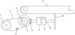
Fig. 1 is the front view according to simultaneously cleaning device of the present invention.
Fig. 2 is the side view according to a preferred embodiment of the simultaneously cleaning device shown in Fig. 1 of the present invention.
Fig. 3 is according to the simultaneously cleaning device work schematic diagram shown in Fig. 1 of the present invention.
The number in the figure explanation:
The first sprocket wheel 1, the second sprocket wheel 2, chain 3, the first sector gear 4, the second sector gears 5, bearing 6, fixed mount 7, hairbrush 8, axostylus axostyle 9, roller 10, regulating wheel 11, bearing block 12, motor 13, weft yarn needle-bar 14.
The specific embodiment
In order to understand better according to simultaneously cleaning device of the present invention, below in conjunction with accompanying drawing, the specific embodiment according to simultaneously cleaning device of the present invention is described.
With reference to figure 1, according to the main cutaway view of simultaneously cleaning device of the present invention.A kind of simultaneously cleaning device, it comprises transmission device, hairbrush 8 and roller 10, roller 10 is driven by motor 13; Hairbrush 8 is positioned at a side of weft yarn needle-bar 14, and described transmission device comprises the first sprocket wheel 1, the second sprocket wheel 2, chain 3, the first sector gear 4 and the second sector gear 5.After the electric motor starting of roller 10 ends, roller 10 starts to roll, and drives transmission device work simultaneously, at this moment changes the cross force of roller 10 into vertical force, and then drives hairbrush 8 to turn clockwise on the cleaning needle-bar by dust catcher, not blotted clean yarn filoplume.
In the present embodiment, described the first sprocket wheel 1, the second sprocket wheel 2 and chain 3 are positioned at a side of roller 10.
In the present embodiment, the lower end of described roller 10 is provided with axostylus axostyle 9.
In the present embodiment, an end of described axostylus axostyle 9 is connected with the first sprocket wheel 2, and the other end is connected with the contiguous block on roller 10.
In the present embodiment, the two ends of described axostylus axostyle 9 are equipped with the first sector gear 4.
In the present embodiment, described the first sector gear 4 and the second sector gear 5 engagements, thus the mechanical force that the level that roller 10 is produced in rotary course is put down changes the vertical force that drives hairbrush 8 rotations into.
In the present embodiment, described the first sector gear 4 and the second sector gear 5 are 45 degree sector gears.
In the present embodiment, the number of teeth of described the first sector gear 4 is 40.
In the present embodiment, the number of teeth of described the second sector gear 5 is 20.
In the present embodiment, described hairbrush 8 is connected with the second sector gear 5 by a connecting rod, and hairbrush 8 coaxially is fixedly connected with the second sector gear 5.
The principle of simultaneously cleaning device of the present invention is: when 14 work of weft yarn needle-bar, the motor 13 of roller 10 1 sides starts, drive bottom roll 10 rotations at motor 13, be positioned at the also rotation thereupon of the first sprocket wheel 1 of roller 10 1 sides, the first sprocket wheel 1 and the second sprocket wheel 2 link together by chain 3 simultaneously.The rotarily driving of the second sprocket wheel 2 is attached thereto the axostylus axostyle 9 connect and rotates, and the first sector gear 4 that drives its two ends in the time of axostylus axostyle 9 rotation starts rotation.Due to the first sector gear 4 and the vertical engagement of the second sector gear 5, thereby the level produced when roller 10 is rotated changes vertical force into to mechanical force.Drive the hairbrush 8 be attached thereto during the second sector gear 5 rotation and turn clockwise, the filoplume on weft yarn needle-bar 14 and dust are outwards cleared up.
In the present embodiment, described hairbrush 8 is the disk hairbrush, has hairbrush tooth and brush plate, and the diameter of described brush plate is the 90-110 millimeter, and thickness is the 10-20 millimeter.In the application, the diameter of brush plate is preferably 100 millimeters, and thickness is preferably 15 millimeters.
In the present embodiment, the material of the hairbrush tooth of described hairbrush 8 is polyethylene.Polyethylene has high ABRASION RESISTANCE, has improved the service life of hairbrush 8, reduces the hairbrush repair and replacement, has guaranteed the normal operation of weft yarn needle-bar 14.
Polyethylene is typical thermoplastic, is odorless, tasteless, nontoxic flammable white powder.The PE resin of processing and forming is all the wax-like particulate material through extruding pelletization, and outward appearance is creamy white.The polyethylene fusing point is that 10-130 degree centigrade of its resistance to low temperature is good, and still can keep good mechanical property under-60 degrees centigrade.Its physical property is: white wax-like trnaslucent materials, and gentle and tough, lighter than water, nontoxic, there are superior dielectric properties.
In the present embodiment, the length of the hairbrush tooth of described hairbrush 8 is the 30-50 millimeter.The length of the hairbrush tooth of hairbrush 8 is preferably 40 millimeters in this application.
Certainly the length of size, thickness and the hairbrush tooth of brush plate diameter all can be selected as required.
Next consult shown in Fig. 2 its side view that is simultaneously cleaning device of the present invention.The first sprocket wheel 1 and the second sprocket wheel 2 link together by chain 3, and the first sprocket wheel 1 and the second sprocket wheel 2 are at grade.The first sprocket wheel 1 and the second sprocket wheel 2 link together by chain 3, when the first sprocket wheel 1 and the second sprocket wheel 2 rotation, the rotarily driving of the second sprocket wheel 2 is attached thereto the axostylus axostyle 9 connect and rotates, and the first sector gear 4 that drives its two ends in the time of axostylus axostyle 9 rotation starts rotation.Due to the first sector gear 4 and the vertical engagement of the second sector gear 5, thereby the level produced when roller 10 is rotated changes vertical force into to mechanical force.Drive the hairbrush 8 be attached thereto during the second sector gear 5 rotation and turn clockwise, the filoplume on weft yarn needle-bar 14 and dust are outwards cleared up away.
In the present embodiment, described chain 3 is provided with regulating wheel 11.Chain 3 in around the first sprocket wheel 1, the second sprocket wheel 2 rotation processes chain 3 of long duration will relax, at this moment will suspend motor 13 chain 3 will be taken off to several joints, so just reduced production efficiency; Otherwise will increase the distance of the first sprocket wheel 1 and the second sprocket wheel 2, and will make like this this device take more space, resource will be caused to waste, when install regulating wheel 11 additional on chain 3, with regard to not there will be chain 3 to vacillate now to the left, now to the right, not take off the phenomenon of chain.
In the present embodiment, described the second sector gear 5 is supported on fixed mount 7 by bearing 6 with the assembly of connecting rod, and bearing 6 is positioned on bearing block 12.The present embodiment middle (center) bearing 6 and bearing block 12 are two, certainly in real work, can increase or reduce according to requirements of one's work the quantity of bearing 6 and bearing block 12.
A kind of replacement scheme of the present invention: above-mentioned chain transmission is replaced with to belt transmission, but there is certain defect in this scheme, there will be belt creep and lax phenomenon, therefore will increase regulating wheel on belt when using belt transmission, the transmission device in this device is worked smoothly.
Finally consult Fig. 3, the work schematic diagram that it is simultaneously cleaning device of the present invention.During work, this cleaning device is placed in a side of weft yarn needle-bar 14, motor 13 startups when roller 10 1 sides, in drive bottom roll 10 rotations of motor 13, be positioned at the also rotation thereupon of the first sprocket wheel 1 of roller 10 1 sides simultaneously, the first sprocket wheel 1 and the second sprocket wheel 2 link together by chain 3.The rotarily driving of the second sprocket wheel 2 is attached thereto the axostylus axostyle 9 connect and rotates, and the first sector gear 4 that drives its two ends in the time of axostylus axostyle 9 rotation starts rotation.Due to the first sector gear 4 and the vertical engagement of the second sector gear 5, thereby the level produced when roller 10 is rotated changes vertical force into to mechanical force.Drive the hairbrush 8 be attached thereto during the second sector gear 5 rotation and turn clockwise, the filoplume on weft yarn needle-bar 14 and dust are outwards cleared up.
In the present embodiment, the first sector gear 4 and the second sector gear 5 all selects the 20CrMnTi material.
Next narrate in the present invention, the processing technology of the first sector gear 4 and the second sector gear 5 is:
1) blanking;
2) blank forging (flat-die forging);
3) tooth base processing;
4) processing keyway, screw thread;
5) profile of tooth roughing and semifinishing;
6) profile of tooth fine finishining;
7) end relief, deburring;
8) check of Geometry Precision of Gear;
9) heat treatment;
10) fine finishining of datum clamp face;
11) tooth Profile Machining again;
12) intensity shot-peening;
13) phosphatization is processed (reduce coefficient of friction, prevent wiping face gummed under top load);
14) the cleaning flank of tooth;
15) Pair test of finished product gear;
16) antirust and packing warehouse-in.
In the present embodiment, the blank of the first sector gear 4 and the second sector gear 5 is processed through the gas carburizing Technology for Heating Processing, and it passes through before processing:
1) normalizing;
Gear Forging Stock after forging is carried out normalizing, and normalizing temperature is 890-950 ℃, and temperature retention time is determined according to forging stock effective dimensions, shove charge situation and the type of furnace.After the forging stock normalizing or the hardness that adds after tempering of normalizing even, single-piece hardness difference≤25HBS, with a collection of difference of hardness≤40HBS.
2) isothermal annealing;
3) destressing;
When module is greater than 14 millimeters, carries out the stress relief annealing processing after profile of tooth roughing or carry out high tempering at 600-650 ℃.
4) flaw detection;
5) surface treatment;
Gasification degreasing in 450-550 ℃ of stove is cleared up or be placed in to the gear for the treatment of carburizing, removes surface and oil contaminant, iron filings and other harmful foreign material.
6) seepage control measure;
The position that gear is not needed to carburizing, can adopt the impermeable coating coated surfaces.Impermeable coating is answered adhesion-tight, after Carburization Treatment, should easily come off, and to the gear surface quality without adverse effect.Also can adopt the seepage control measures such as copper facing or reserved processing capacity.
7) with the stove sample;
8) the carburizing raw material chooses.
Select the drop-feeding gas carburization stove as heat treated equipment, any makes carburizer to adopt special-purpose carburizing oil, kerosene, acetone, isopropyl alcohol, ethyl acetate, toluene etc., with methyl alcohol, makes diluent.
Above-mentioned gas carburizing process of thermal treatment is:
1) shove charge;
Be placed on stone tongs by ready gear with the stove sample, when gear is contained on fixture, between the gear teeth, overlap joint must not be arranged, and should leave enough gaps between gear teeth working face.
2) exhaust;
After the gear shove charge, temperature splashes into methyl alcohol while reaching more than 750 ℃ in a large number, passes into carburizer after reaching 850 ℃ again.When adopting the easy distortion of pit gas carburizing furnace processing and reliability to require high gear and batch than ambassador, should take segmentation samming mode of heating, pass into nitrogen simultaneously and start exhaust, furnace temperature splashes into methyl alcohol after rising to 750 ℃.
When furnace temperature reaches the carburizing temperature of setting, and Carbon Potential Inside Furnace is exhaust and finishes while reaching 0.8%, proceeds to by force and oozes the stage.
3) control of carburizing temperature and time;
Carburizing temperature is controlled at 890-930 ℃, and carburizing time is determined according to carburizing temperature.
4) diffusion;
This gear requires the infiltration layer gradient mild, therefore spread after oozing by force.For the gas of carbon potential in can the fast reducing stove, therefore add nitrogen, air etc.
5) control of carbon potential;
Do not occurring under the prerequisite that carbon black and surface of the work carbide rank allow, keeping the highest carbon potential in the carburazing period stove, to obtain the fastest infiltration rate.
6) with temperature, process;
Material selection 20CrMnTi due to this gear, need direct quenching, in carburizer, be cooled to after 840-860 ℃ of insulation 0.5-1h drop in hardening media cooling.Can adopt air cooling while certainly for face of gear, larger allowance being arranged.
7) direct quenching;
8) Repeat-heating quenches;
Owing to needing machining after carburizing or owing to after the steel characteristics carburizing, needing precooling.
9) clean;
Cleaned removal of contamination through quench cooled at gear to proper temperature.
10) tempering;
Timely lonneal after gear cleans, general interval is no more than 4h.In the present embodiment, the temperature of tempering is 160-220 ℃, and tempering time is 2-4h.
11) cold treatment;
The accuracy of gear in the present embodiment is not that requirement is too high, therefore do not need to carry out cold treatment.
12) sandblast or shot-peening.
Gear after heat treatment carries out abrasive jet cleaning or shot peening strengthening as requested, to improve bending fatigue strength and the contact fatigue strength of gear.
In sum, in whole weft yarn equipment, simultaneously cleaning device of the present invention is positioned at the centre position of this equipment, can carry out cleaning to the weft yarn needle-bar 14 of both sides, thereby efficiency is provided, and has reduced cost simultaneously.This cleaning device is used the machine power produced when roller rolls and is driven transmission device work, the use of having saved motor, and power consumption is low, maintenance cost is low, not fragile.It is higher that sector gear in the present invention has ABRASION RESISTANCE, and long service life, through Overheating Treatment trailing wheel tooth characteristics such as easy fracture not.
It will be apparent to those skilled in the art that simultaneously cleaning device of the present invention comprises any combination of each several part in this specification.As space is limited and in order to make specification simple and clear, at this, these combinations are not introduced one by one in detail, but, after having seen this specification, the scope of the present invention that any combination of the each several part consisted of this specification forms is self-evident.
Claims (10)
1. a simultaneously cleaning device, it comprises transmission device, hairbrush (8) and roller (10), roller (10) is driven by motor (13); Hairbrush (8) is positioned at a side of weft yarn needle-bar (14), it is characterized in that: described transmission device comprises the first sprocket wheel (1), the second sprocket wheel (2), chain (3), the first sector gear (4) and the second sector gear (5).
2. simultaneously cleaning device as claimed in claim 1, it is characterized in that: the first sprocket wheel (1), the second sprocket wheel (2) and chain (3) are positioned at a side of roller (10).
3. simultaneously cleaning device as claimed in claim 1 or 2, it is characterized in that: chain (3) is provided with regulating wheel (11).
4. simultaneously cleaning device as claimed in claim 1, it is characterized in that: the lower end of roller (10) is provided with axostylus axostyle (9).
5. simultaneously cleaning device as claimed in claim 4, it is characterized in that: an end of axostylus axostyle (9) is connected with the first sprocket wheel (2), and the other end is connected with the contiguous block on roller (10).
6. simultaneously cleaning device as described as claim 4 or 5, it is characterized in that: the two ends of axostylus axostyle (9) are equipped with the first sector gear (4).
7. simultaneously cleaning device as claimed in claim 1, is characterized in that: the first sector gear (4) and the second sector gear (5) engagement.
8. simultaneously cleaning device as described as claim 1 or 7, it is characterized in that: the first sector gear (4) and the second sector gear (5) are 45 degree sector gears.
9. simultaneously cleaning device as described as claim 1 or 7, it is characterized in that: the number of teeth of the first sector gear (4) is 40.
10. simultaneously cleaning device as described as claim 1 or 7, it is characterized in that: the number of teeth of the second sector gear (5) is 20.
Priority Applications (1)
| Application Number | Priority Date | Filing Date | Title |
|---|---|---|---|
| CN2013103870469A CN103437062A (en) | 2013-08-30 | 2013-08-30 | Synchronous cleaning device |
Applications Claiming Priority (1)
| Application Number | Priority Date | Filing Date | Title |
|---|---|---|---|
| CN2013103870469A CN103437062A (en) | 2013-08-30 | 2013-08-30 | Synchronous cleaning device |
Publications (1)
| Publication Number | Publication Date |
|---|---|
| CN103437062A true CN103437062A (en) | 2013-12-11 |
Family
ID=49690774
Family Applications (1)
| Application Number | Title | Priority Date | Filing Date |
|---|---|---|---|
| CN2013103870469A Pending CN103437062A (en) | 2013-08-30 | 2013-08-30 | Synchronous cleaning device |
Country Status (1)
| Country | Link |
|---|---|
| CN (1) | CN103437062A (en) |
Cited By (3)
| Publication number | Priority date | Publication date | Assignee | Title |
|---|---|---|---|---|
| CN104999237A (en) * | 2014-08-14 | 2015-10-28 | 苏州优金金属成型科技有限公司 | Forging process for car spline shaft gear |
| CN107313172A (en) * | 2016-05-20 | 2017-11-03 | 乐清市华尊电气有限公司 | A kind of dust guard of computer jacquard |
| CN108018838A (en) * | 2017-12-12 | 2018-05-11 | 曹诗晴 | A kind of environmental protection humanoid robot |
Citations (9)
| Publication number | Priority date | Publication date | Assignee | Title |
|---|---|---|---|---|
| SU896109A1 (en) * | 1980-04-19 | 1982-01-07 | За витель | Needle bar cleaning mechanism to flat knitting machine |
| JP2003250726A (en) * | 2002-03-01 | 2003-09-09 | Kozo Iketani | Flooring wax cleaner head for vacuum cleaner |
| CN201074260Y (en) * | 2007-06-26 | 2008-06-18 | 鲁泰纺织股份有限公司 | Roller self-cleaning device for ring spinning frame |
| CN201197692Y (en) * | 2008-04-30 | 2009-02-25 | 亓翠 | Portable dust-cleaning equipment for book |
| CN101676073A (en) * | 2008-09-18 | 2010-03-24 | 刘昕 | Mechanical cleaning arm of cleaning machine |
| CN201530895U (en) * | 2009-11-11 | 2010-07-21 | 际华三五零九纺织有限公司 | Accelerating transmission system used for up-and-down cleaning device of roving machine |
| CN102979884A (en) * | 2012-11-23 | 2013-03-20 | 无锡威孚中意齿轮有限责任公司 | Mine vehicle axle wheel reductor planetary gear and manufacture method thereof |
| CN202968839U (en) * | 2012-11-20 | 2013-06-05 | 山东新易丰毛绒制品有限公司 | Wheel type cleanser used in spinning workshop |
| CN203530598U (en) * | 2013-08-30 | 2014-04-09 | 振石集团恒石纤维基业有限公司 | Synchronous cleaning device |
-
2013
- 2013-08-30 CN CN2013103870469A patent/CN103437062A/en active Pending
Patent Citations (9)
| Publication number | Priority date | Publication date | Assignee | Title |
|---|---|---|---|---|
| SU896109A1 (en) * | 1980-04-19 | 1982-01-07 | За витель | Needle bar cleaning mechanism to flat knitting machine |
| JP2003250726A (en) * | 2002-03-01 | 2003-09-09 | Kozo Iketani | Flooring wax cleaner head for vacuum cleaner |
| CN201074260Y (en) * | 2007-06-26 | 2008-06-18 | 鲁泰纺织股份有限公司 | Roller self-cleaning device for ring spinning frame |
| CN201197692Y (en) * | 2008-04-30 | 2009-02-25 | 亓翠 | Portable dust-cleaning equipment for book |
| CN101676073A (en) * | 2008-09-18 | 2010-03-24 | 刘昕 | Mechanical cleaning arm of cleaning machine |
| CN201530895U (en) * | 2009-11-11 | 2010-07-21 | 际华三五零九纺织有限公司 | Accelerating transmission system used for up-and-down cleaning device of roving machine |
| CN202968839U (en) * | 2012-11-20 | 2013-06-05 | 山东新易丰毛绒制品有限公司 | Wheel type cleanser used in spinning workshop |
| CN102979884A (en) * | 2012-11-23 | 2013-03-20 | 无锡威孚中意齿轮有限责任公司 | Mine vehicle axle wheel reductor planetary gear and manufacture method thereof |
| CN203530598U (en) * | 2013-08-30 | 2014-04-09 | 振石集团恒石纤维基业有限公司 | Synchronous cleaning device |
Non-Patent Citations (1)
| Title |
|---|
| 王万智等: "《钢的渗碳》", 30 September 1985, 机械工业出版社 * |
Cited By (5)
| Publication number | Priority date | Publication date | Assignee | Title |
|---|---|---|---|---|
| CN104999237A (en) * | 2014-08-14 | 2015-10-28 | 苏州优金金属成型科技有限公司 | Forging process for car spline shaft gear |
| CN107313172A (en) * | 2016-05-20 | 2017-11-03 | 乐清市华尊电气有限公司 | A kind of dust guard of computer jacquard |
| CN107313172B (en) * | 2016-05-20 | 2019-01-25 | 乐清市华尊电气有限公司 | A kind of dust guard of computer jacquard |
| CN108018838A (en) * | 2017-12-12 | 2018-05-11 | 曹诗晴 | A kind of environmental protection humanoid robot |
| CN108018838B (en) * | 2017-12-12 | 2019-11-12 | 曹诗晴 | A kind of environmental protection humanoid robot |
Similar Documents
| Publication | Publication Date | Title |
|---|---|---|
| CN203530598U (en) | Synchronous cleaning device | |
| CN102766751B (en) | Process method for quenching rotary support gear | |
| CN103437062A (en) | Synchronous cleaning device | |
| CN113088665B (en) | Special camshaft high-frequency quenching equipment | |
| CN101691010A (en) | Multifunctional numerical control equipment | |
| JP6480423B2 (en) | Conveyor furnace | |
| CN108202088A (en) | A kind of processing method of small dimension titanium or titanium alloy Bar Wire Product | |
| RU2529147C2 (en) | Repair of hollow rolls of centrifugal machine for production of mineral cotton | |
| CN110923437A (en) | Metal plate strip heat treatment spiral roller way | |
| CN201183812Y (en) | Middle and small type bearing sleeve ring heat-treatment quenching machine | |
| CN113386036A (en) | Self-deslagging bearing grinding process and grinding device thereof | |
| CN101805882A (en) | Process for controlling deformation of gas nitrocarburizing part | |
| CN106826036B (en) | A kind of segmented thin-wall circular tube deposition apparatus | |
| CN212864887U (en) | Electric heating quenching device for motorcycle crank | |
| CN101942556A (en) | Laser quenching treatment method for corrugator roll | |
| CN210796569U (en) | High-frequency continuous quenching device for chain wheel | |
| CN213172450U (en) | Quenching cleaning device for shaft forging | |
| CN114517255A (en) | Medium-frequency induction quenching method for surface of large diesel engine crankshaft | |
| CN113667812A (en) | Processing method of medium carbon alloy steel non-soft-belt large-scale rolling mill bearing | |
| CN207828377U (en) | One kind being used for crankshaft-synchronous heat-treating apparatus | |
| CN203487198U (en) | Gasket group for thermal treatment on gear hub | |
| KR20220043723A (en) | high frequency heat treatment device for stator shaft | |
| CN206956094U (en) | A kind of feed system of heat treatment two chamber vacuum furnace | |
| CN112301201A (en) | Continuous annealing furnace and method for continuous solution treatment of medium plate by using same | |
| CN107297597A (en) | A kind of production method of automobile trunk elevating lever |
Legal Events
| Date | Code | Title | Description |
|---|---|---|---|
| C06 | Publication | ||
| PB01 | Publication | ||
| C10 | Entry into substantive examination | ||
| SE01 | Entry into force of request for substantive examination | ||
| C05 | Deemed withdrawal (patent law before 1993) | ||
| WD01 | Invention patent application deemed withdrawn after publication |
Application publication date: 20131211 |