CN103246789A - Computing method of deformation of annular sandwich valve plates of vibration absorber under non-uniform pressure - Google Patents
Computing method of deformation of annular sandwich valve plates of vibration absorber under non-uniform pressure Download PDFInfo
- Publication number
- CN103246789A CN103246789A CN2013102122738A CN201310212273A CN103246789A CN 103246789 A CN103246789 A CN 103246789A CN 2013102122738 A CN2013102122738 A CN 2013102122738A CN 201310212273 A CN201310212273 A CN 201310212273A CN 103246789 A CN103246789 A CN 103246789A
- Authority
- CN
- China
- Prior art keywords
- valve plate
- deformation
- radius
- annular
- uniform pressure
- Prior art date
- Legal status (The legal status is an assumption and is not a legal conclusion. Google has not performed a legal analysis and makes no representation as to the accuracy of the status listed.)
- Pending
Links
- 239000006096 absorbing agent Substances 0.000 title claims abstract description 104
- 238000004364 calculation method Methods 0.000 title claims abstract description 58
- 230000035939 shock Effects 0.000 claims abstract description 103
- 238000000034 method Methods 0.000 claims abstract description 10
- 239000000463 material Substances 0.000 claims description 5
- 230000000977 initiatory effect Effects 0.000 claims description 3
- 238000004088 simulation Methods 0.000 abstract description 35
- 238000013461 design Methods 0.000 abstract description 22
- 238000012360 testing method Methods 0.000 abstract description 2
- 238000012795 verification Methods 0.000 abstract description 2
- 238000009826 distribution Methods 0.000 description 11
- 230000008859 change Effects 0.000 description 3
- 238000010586 diagram Methods 0.000 description 3
- 238000013178 mathematical model Methods 0.000 description 3
- 230000006872 improvement Effects 0.000 description 2
- 238000011160 research Methods 0.000 description 2
- 239000007787 solid Substances 0.000 description 2
- 230000008901 benefit Effects 0.000 description 1
- 238000007906 compression Methods 0.000 description 1
- 230000006835 compression Effects 0.000 description 1
- 238000013016 damping Methods 0.000 description 1
- 230000007547 defect Effects 0.000 description 1
- 238000011161 development Methods 0.000 description 1
- 238000009472 formulation Methods 0.000 description 1
- 238000009828 non-uniform distribution Methods 0.000 description 1
- 230000008569 process Effects 0.000 description 1
- 238000011084 recovery Methods 0.000 description 1
Images


Landscapes
- Testing Of Devices, Machine Parts, Or Other Structures Thereof (AREA)
Abstract
本发明涉及减振器环形叠加阀片在非均布压力下变形的计算方法,属于减振器技术领域,其特征在于:首先计算出环形叠加阀片的等效厚度,在非均布压力下的环形阀片在任意半径处的变形系数;然后,根据等效厚度、变形系数及非均布压力最大值,对减振器环形叠加阀片在非均布压力下的在任意半径处的变形进行计算。通过计算实例及ANSYS仿真验证结果可知,该方法可对减振器环形叠加阀片在非均布压力下任意半径位置变形进行精确计算,利用该方法可建立精确的减振器参数设计及特性仿真模型,可得到准确、可靠的减振器节流阀参数设计值及减振器特性仿真值,从而降低减振器设计及试验费用,提高设计水平、质量和性能及车辆行驶平顺性。

The invention relates to a calculation method for the deformation of an annular superimposed valve plate of a shock absorber under non-uniform pressure, and belongs to the technical field of shock absorbers. The deformation coefficient of the annular valve plate at any radius; then, according to the equivalent thickness, deformation coefficient and the maximum value of non-uniform pressure, the deformation of the annular superimposed valve plate of the shock absorber at any radius under non-uniform pressure Calculation. Through calculation examples and ANSYS simulation verification results, it can be seen that this method can accurately calculate the deformation of the annular superimposed valve plate of the shock absorber at any radial position under non-uniform pressure, and use this method to establish accurate shock absorber parameter design and characteristic simulation The model can obtain accurate and reliable shock absorber throttle valve parameter design values and shock absorber characteristic simulation values, thereby reducing shock absorber design and test costs, improving design level, quality and performance, and vehicle ride comfort.
Description
技术领域 technical field
本发明涉及减振器,特别是减振器环形叠加阀片在非均布压力下变形的计算方法。 The invention relates to a shock absorber, in particular to a calculation method for deformation of an annular superimposed valve plate of the shock absorber under non-uniform pressure.
背景技术 Background technique
复原阀和压缩阀的环形叠加阀片是减振器中最为关键性的精密元件,在阀口半径位置的阀片变形对减振器阻尼特性具有重要影响,因此,能否实现对环形叠加阀片变形的精确计算,决定着能否建立精确的减振器阀参数设计及减振器特性仿真数学模型,得到准确的减振器节流阀参数设计值及特性仿真值,并且决定着能否真正实现汽车减振器的现代化CAD设计及计算机特性仿真。由于减振器常通节流孔和节流缝隙的存在,减振器阀片实际所受的压力并不是均布的而实际是非均布的, 尽管国内、外很多学者已对此进行了大量研究,但是对于在非均布载荷下的阀片变形计算至今还没有给出精确的解析计算式及计算方法。目前国内外大都是利用有限元仿真软件,对给定压力下的阀片通过建立实体模型进行数值仿真,尽管可得到近似的数值解,但是不能满足减振器阀参数精确设计及特性仿真的要求。我国在减振器环形叠加阀片变形计算方面的研究取得了重要突破,但只能对均布压力下的环形叠加阀片变形精确解析计算,但是由于减振器环形叠加阀片所受压力为非均布的,要建立精确的减振器设计及特性仿真数学模型,必须解决减振器环形叠加阀片在非均布压力下的变形精确解析计算问题。随着汽车工业的快速发展及车辆行驶速度的不断提高,对减振器设计提出了更高的要求,要实现减振器现代化CAD设计及特性计算仿真,必须建立一种精确的减振器环形叠加阀片在非均布压力下的变形计算方法,满足减振器设计及特性仿真精确建模的要求,使减振器参数设计值更加准确,特性仿真值更加可靠,提高减振器设计水平和产品性能,满足车辆行驶平顺性对减振器特性不断提高的要求。 The annular superimposed valve plate of the recovery valve and the compression valve is the most critical precision component in the shock absorber. The deformation of the valve plate at the radial position of the valve port has an important impact on the damping characteristics of the shock absorber. Therefore, whether the annular superimposed valve can be realized The accurate calculation of sheet deformation determines whether the accurate shock absorber valve parameter design and shock absorber characteristic simulation mathematical model can be established, and the accurate shock absorber throttle valve parameter design value and characteristic simulation value can be obtained, and whether it can be determined Realize the modern CAD design and computer characteristic simulation of automobile shock absorber. Due to the existence of the normally open orifice and the throttling gap of the shock absorber, the actual pressure on the shock absorber valve plate is not uniform but actually non-uniform, although many domestic and foreign scholars have done a lot of research on this However, there is no accurate analytical calculation formula and calculation method for the deformation calculation of valve plate under non-uniform load. At present, finite element simulation software is mostly used at home and abroad to conduct numerical simulation of the valve plate under a given pressure by establishing a solid model. Although an approximate numerical solution can be obtained, it cannot meet the requirements of accurate design of shock absorber valve parameters and characteristic simulation. . Our country has made an important breakthrough in the research on the deformation calculation of the annular superimposed valve plate of the shock absorber, but it can only accurately calculate the deformation of the annular superimposed valve plate under uniform pressure, but because the pressure on the annular superimposed valve plate of the shock absorber is Non-uniform distribution, in order to establish an accurate shock absorber design and characteristic simulation mathematical model, it is necessary to solve the problem of accurate analytical calculation of the deformation of the annular superimposed valve plate of the shock absorber under non-uniform pressure. With the rapid development of the automobile industry and the continuous improvement of vehicle speed, higher requirements are put forward for the design of shock absorbers. To realize the modern CAD design and characteristic calculation and simulation of shock absorbers, it is necessary to establish an accurate shock absorber ring The deformation calculation method of superimposed valve plates under non-uniform pressure meets the requirements of shock absorber design and accurate modeling of characteristic simulation, making the design value of shock absorber parameters more accurate, the characteristic simulation value more reliable, and improving the design level of shock absorber And product performance, to meet the continuous improvement of vehicle ride comfort on the characteristics of shock absorbers.
发明内容 Contents of the invention
针对上述现有技术中存在的缺陷,本发明所要解决的技术问题是提供一种精确、可靠的减振器环形叠加阀片在非均布压力下变形的计算方法。 In view of the above-mentioned defects in the prior art, the technical problem to be solved by the present invention is to provide an accurate and reliable calculation method for the deformation of the annular superimposed valve plate of the shock absorber under non-uniform pressure.
为了解决上述技术问题,本发明所提供的减振器环形叠加阀片在非均布压力下变形的计算方法,其技术方案实施步骤如下: In order to solve the above-mentioned technical problems, the method for calculating the deformation of the ring-shaped superimposed valve plate of the shock absorber under non-uniform pressure provided by the present invention, the implementation steps of the technical solution are as follows:
(1)确定减振器环形叠加阀片的等效厚度h e: (1) Determine the equivalent thickness h e of the annular superimposed valve plate of the shock absorber:
对于材料特性相同、内圆半径 


(2)均布压力下p 0下叠加阀片在任意半径r位置的变形系数G r1的计算: (2) Calculation of the deformation coefficient G r 1 of the superimposed valve plate at any radius r position under p 0 under uniform pressure:
根据减振器环形叠加阀片的内圆半径r a,外圆半径r b,弹性模量E和泊松比μ,计算在均布压力下的环形阀片在任意半径r(r a ≤r≤ r b )位置的变形系数G r1,即: According to the inner circle radius r a , outer circle radius r b , elastic modulus E and Poisson's ratio μ of the annular superimposed valve plate of the shock absorber, calculate the annular valve plate under uniform pressure at any radius r ( r a ≤ r ≤ r b ) the deformation coefficient G r 1 at the position, namely:

式中,


(3)反向线性非均布压力
根据环形阀片的内圆半径r a,外圆半径r b,弹性模量E,泊松比μ,非均布压力的起始作用位置半径r k,计算在反向线性非均布压力下的环形叠加阀片变形系数,即: According to the radius r a of the inner circle of the ring valve, the radius r b of the outer circle, the elastic modulus E , Poisson's ratio μ , and the radius r k of the initial action position of the non-uniform pressure, it is calculated under the reverse linear non-uniform pressure The deformation coefficient of the annular superimposed valve plate, that is:

式中, In the formula,


其中,
(4)减振器环形叠加阀片在任意半径r位置的变形系数G r 计算: (4) Calculation of the deformation coefficient G r of the annular superimposed valve plate of the shock absorber at any position of radius r :
根据步骤(2)中的G r1和步骤(3)中的G r2,通过叠加运算确定环形阀片在任意半径r(r a ≤r≤ r b )位置的总叠加变形系数G r ,即 According to G r 1 in step (2) and G r 2 in step (3), the total superimposed deformation coefficient G r of the annular valve plate at any radius r ( r a ≤ r ≤ r b ) position is determined by superposition operation, Right now
; ;
(5)减振器环形叠加阀片在任意半径r位置的变形f r 计算: (5) Calculation of the deformation f r of the annular superimposed valve plate of the shock absorber at any position of radius r :
根据环形叠加阀片所受的最大非均布压力p 0,步骤(1)中的等效厚度h e,及步骤(3)中的变形系数G r ,对非均布压力下的减振器环形叠加阀片在半径r位置的变形量f r 进行计算,即: According to the maximum non-uniform pressure p 0 of the annular superimposed valve plate, the equivalent thickness he in step (1), and the deformation coefficient G r in step (3), the shock absorber under non-uniform pressure The deformation amount f r of the annular superimposed valve plate at the position of radius r is calculated, namely:

本发明比现有技术具有的优点: The present invention has the advantage over prior art:
由于实际减振器大多采用环形叠加节流阀片,且所受压力为非均布的,先前尽管已给出了在均布压力下的变形计算方法,但计算得到阀口半径处变形量与实际阀片变形量相差较大,因此,所建立的减振器节流阀参数设计及特性仿真模型不够精确,参数设计值及特性仿真值还不够可靠。对于减振器环形叠加阀片在非均布压力下的变形,先前国内、外均无给出精确、可靠的计算方法,大都是利用有限元仿真软件,对给定压力下的阀片通过建立实体模型进行数值仿真得到近似的数值解,不能满足减振器节流阀参数设计及特性仿真精确建模要求。本发明所建立的减振器环形叠加阀片在非均布压力下变形的计算方法,首先,根据环形叠加阀片的厚度和片数,计算出环形叠加阀片的等效厚度;然后,将减振器环形叠加阀片在非均布压力下的力学模型,看作为均布压力与反向线性非均布压力的叠加,利用均布压力下的环形阀片在任意半径r位置的变形系数G r1,及反向线性非均布压力下的环形阀片在任意半径r位置的变形系数G r2,通过叠加计算得到环形阀片在非均布压力下的叠加变形系数G r =G r2+G r1;随后,根据叠加阀片等效厚度、叠加变形系数G r 和最大非均布压力值,对减振器环形叠加阀片在非均布压力下的变形进行计算。通过计算实例与ANSYS仿真验证结果比较可知,该减振器环形叠加阀片在非均布压力下变形的计算方法准确、可靠,并且可对阀片在任意半径r位置处的变形量进行精确计算,因此,为建立精确的减振器节流阀参数设计及特性仿真模型,提供了精确的环形叠加阀片在非均布压力下变形的计算方法,确保减振器节流阀参数设计及特性仿真值准确可靠,从而降低减振器设计及试验费用,提高减振器的设计水平、质量和性能。 Since most of the actual shock absorbers use annular superimposed throttle valve plates, and the pressure is not uniform, although the deformation calculation method under uniform pressure has been given before, the calculated deformation at the radius of the valve port is the same as The actual deformation of the valve plate is quite different. Therefore, the established parameter design and characteristic simulation model of the shock absorber throttle valve is not accurate enough, and the parameter design value and characteristic simulation value are not reliable enough. For the deformation of the annular superimposed valve plate of the shock absorber under non-uniform pressure, no accurate and reliable calculation method has been given before at home and abroad. Most of them use finite element simulation software to establish Numerical simulation of the solid model can obtain an approximate numerical solution, which cannot meet the requirements of accurate modeling of shock absorber throttle valve parameter design and characteristic simulation. The method for calculating the deformation of the annular superimposed valve plate of the shock absorber under non-uniform pressure, first, calculates the equivalent thickness of the annular superimposed valve plate according to the thickness and the number of the annular superimposed valve plate; then, the The mechanical model of the annular superimposed valve plate of the shock absorber under the non-uniform pressure is regarded as the superposition of the uniform pressure and the reverse linear non-uniform pressure, and the deformation coefficient of the annular valve plate under the uniform pressure at any radius r position is used G r 1 , and the deformation coefficient G r 2 of the annular valve plate at any radius r position under the reverse linear non-uniform pressure, and the superimposed deformation coefficient G r = G of the annular valve plate under non-uniform pressure through superposition calculation r 2 + G r 1 ; then, according to the equivalent thickness of the superimposed valve plate, the superimposed deformation coefficient G r and the maximum non-uniform pressure value, the deformation of the annular superimposed valve plate of the shock absorber under the non-uniform pressure is calculated. Through the comparison of the calculation example and the ANSYS simulation verification results, it can be seen that the calculation method of the deformation of the annular superimposed valve plate of the shock absorber under non-uniform pressure is accurate and reliable, and the deformation amount of the valve plate at any radius r position can be accurately calculated , therefore, in order to establish an accurate shock absorber throttle valve parameter design and characteristic simulation model, an accurate calculation method for the deformation of the annular superimposed valve plate under non-uniform pressure is provided to ensure that the shock absorber throttle valve parameter design and characteristic The simulation value is accurate and reliable, thereby reducing the design and test costs of the shock absorber, and improving the design level, quality and performance of the shock absorber.
为了更好地理解本发明下面结合附图作进一步的说明。 In order to better understand the present invention, the following will be further described in conjunction with the accompanying drawings.
图1 是减振器环形叠加阀片在非均布压力下变形的计算流程图; Figure 1 is a calculation flow chart of the deformation of the annular superimposed valve plate of the shock absorber under non-uniform pressure;
图2 是减振器环形叠加阀片非均布压力的力学模型; Figure 2 is the mechanical model of the non-uniform pressure distribution of the annular superimposed valve plate of the shock absorber;
图3 是实施例一的环形叠加阀片在均布压力下的变形系数G r1; Fig. 3 is the deformation coefficient G r 1 of the annular stacked valve plate in the first embodiment under uniform pressure;
图4 是实施例一的环形叠加阀片在反向线性非均布压力下的变形系数G r2; Fig. 4 is the deformation coefficient G r 2 of the annular stacked valve plate in the first embodiment under the reverse linear non-uniform pressure;
图5 是实施例一的减振器环形叠加阀片在非均布压力下的变形系数G r ; Fig. 5 is the deformation coefficient G r of the annular stacked valve plate of the shock absorber under non-uniform pressure in the first embodiment;
图6 是实施例一的减振器环形叠加阀片在非均布压力下的变形曲线; Fig. 6 is the deformation curve of the annular stacked valve plate of the shock absorber under non-uniform pressure of embodiment one;
图7 是实施例一的减振器环形叠加阀片在非均布压力下的变形仿真云图; Fig. 7 is the simulation cloud diagram of the deformation of the annular superimposed valve plate of the shock absorber under the non-uniform pressure of the first embodiment;
图8 是实施例二的环形叠加阀片在反向线性非均布压力下的变形系数G r2; Fig. 8 is the deformation coefficient G r 2 of the annular stacked valve plate of the second embodiment under the reverse linear non-uniform pressure;
图9 是实施例二的减振器环形叠加阀片在非均布压力下的变形系数G r ; Fig. 9 is the deformation coefficient G r of the annular stacked valve plate of the shock absorber under non-uniform pressure in the second embodiment;
图10 是实施例二的减振器环形叠加阀片在非均布压力下的变形曲线; Fig. 10 is the deformation curve of the annular stacked valve plate of the shock absorber under non-uniform pressure of embodiment two;
图11是实施例二的减振器环形叠加阀片在非均布压力下的变形仿真云图; Fig. 11 is the simulation cloud diagram of the deformation of the annular superimposed valve plate of the shock absorber under non-uniform pressure in the second embodiment;
图12是实施例三的环形叠加阀片在均布压力下的变形系数G r1; Fig. 12 is the deformation coefficient G r 1 of the annular stacked valve plate in the third embodiment under uniform pressure;
图13 是实施例三的环形叠加阀片在反向线性非均布压力下的变形系数G r2; Fig. 13 is the deformation coefficient G r 2 of the annular stacked valve plate in the third embodiment under the reverse linear non-uniform pressure;
图14 是实施例三的减振器环形叠加阀片在非均布压力下的变形系数G r ; Fig. 14 is the deformation coefficient G r of the annular superimposed valve plate of the shock absorber under non-uniform pressure in the third embodiment;
图15 是实施例三的减振器环形叠加阀片在非均布压力下的变形曲线; Fig. 15 is the deformation curve of the annular superimposed valve plate of the shock absorber under the non-uniform pressure of the third embodiment;
图16是实施例三的减振器环形叠加阀片在非均布压力下的变形仿真云图。 Fig. 16 is a simulation cloud diagram of the deformation of the annular superimposed valve plate of the shock absorber under non-uniform pressure in the third embodiment.
具体实施方案 specific implementation plan
下面通过实施例对本发明作进一步详细说明。 The present invention will be described in further detail below by way of examples.
实施例一:某减振器等构环形叠加阀片的内圆半径r a=5.0mm,外圆半径r b=8.5mm,阀口半径r k=8.0mm;弹性模量E=200GPa,泊松比μ=0.3;叠加阀片的厚度和片数,分别为h 1=0.1mm,n 1=3;h 2=0.15mm,n 2=2;h 3=0.2mm,n 3=1;非均布最大压力p 0=3.0MPa。 Example 1: The inner circle radius r a = 5.0mm, the outer circle radius r b = 8.5mm, the valve port radius r k = 8.0mm; the modulus of elasticity E = 200GPa, poise Loose ratio μ = 0.3; the thickness and number of stacked valve plates are h 1 =0.1mm, n 1 =3; h 2 =0.15mm, n 2 =2; h 3 =0.2mm, n 3 =1; Non-uniform maximum pressure p 0 =3.0MPa.
本发明实例所提供的减振器环形叠加阀片变形的计算方法,其计算流程如图1所示,减振器环形叠加阀片的力学模型如图2所示,具体步骤如下: The calculation method for the deformation of the annular superimposed valve plate of the shock absorber provided by the example of the present invention, its calculation process is shown in Figure 1, and the mechanical model of the annular superimposed valve plate of the shock absorber is shown in Figure 2, and the specific steps are as follows:
(1)确定环形叠加阀片的等效厚度h e: (1) Determine the equivalent thickness h e of the annular stacked valve plate:
根据某减振器等构环形叠加阀片的厚度和片数h 1=0.1mm,n 1=3;h 2=0.15mm,n 2=2; h 3=0.2mm,n 3=1,等构环形叠加阀片的等效厚度h e为: According to the thickness and number of isostructured annular superimposed valve plates of a certain shock absorber h 1 =0.1mm, n 1 =3; h 2 =0.15mm, n 2 =2; h 3 =0.2mm, n 3 =1, etc. The equivalent thickness h e of the ring-shaped superimposed valve plate is:

(2)均布压力下环形叠加阀片在任意半径r位置变形系数G r1的计算: (2) Calculation of the deformation coefficient G r 1 of the annular superimposed valve plate at any radius r position under uniform pressure:
根据减振器环形叠加阀片的E=2.0

式中, 

, ,


计算得到变形系数G r1随半径r(r a ≤r≤ r b )的变化曲线,如图3所示; Calculate the variation curve of the deformation coefficient G r 1 with the radius r ( r a ≤ r ≤ r b ), as shown in Figure 3;
(3)反向线性非均布压力下的阀片在任意半径r位置变形系数G r2 的计算: (3) Calculation of the deformation coefficient G r 2 of the valve plate at any radius r position under reverse linear non-uniform pressure:
根据环形阀片的内圆半径r a=5.0mm,外圆半径r b=8.5mm,弹性模量E=2.0

式中, 


,


计算得到在反向线性非均布压力下的阀片在任意半径r位置变形系数G r2随半径r (r a ≤r≤ r b )的变化曲线,如图4所示; Calculate the change curve of the deformation coefficient G r 2 of the valve plate at any radius r position with the radius r ( r a ≤ r ≤ r b ) under the reverse linear non-uniform pressure, as shown in Figure 4;
(4)减振器环形叠加阀片在任意半径r位置的叠加变形系数G r 计算: (4) Calculation of the superimposed deformation coefficient G r of the annular superimposed valve plate of the shock absorber at any radius r position:
根据步骤(2)中的G r1和步骤(3)中的G r2,通过叠加运算得减振器环形叠加阀片的变形系数G r 随半径r(r a ≤r≤ r b )的变化曲线,如图5所示; According to G r 1 in step (2) and G r 2 in step (3), the deformation coefficient G r of the annular superimposed valve plate of the shock absorber varies with the radius r ( r a ≤ r ≤ r b ) through superposition calculation Variation curve, as shown in Figure 5;
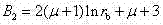
其中,在阀口半径r k位置的变形系数G rk=m6/N,在外圆半径r b位置的变形系数G rb=
(5)阀片在任意半径r位置的叠加变形f r 计算: (5) Calculation of the superimposed deformation f r of the valve plate at any radius r position:
根据步骤(1)中的叠加阀片等效厚度h e=0.260855mm,在区间r a ≤r≤r b的分布压力p 0=3.0MPa,在区间r k <r≤r b 的分布的压力p=

计算所得到的减振器环形叠加阀片变形曲线,如图6所示; The calculated deformation curve of the annular superimposed valve plate of the shock absorber is shown in Figure 6;
其中,叠加阀片在阀口半径位置的变形量为
根据减振器环形叠加阀片的内圆半径r a=5.0mm,外圆半径r b=8.5mm,弹性模型E=200GPa,泊松比μ=0.3,叠加阀片的厚度和片数分别为h 1=0.1mm,n 1=3;h 2=0.15mm,n 2=2;h 3=0.2mm,n 3=1;利用ANSYS建立叠加阀片仿真模型,网格划分单位为0.1mm,在区间r a ≤r≤ r b 的分布压力p 0=3.0MPa,在区间r k <r≤ r b 的分布的压力p=
由图7可知,减振器环形叠加阀片最大变形仿真值为0.154293mm,与利用该计算方法所得到的0.154023mm之间的偏差为0.00027mm,相对偏差仅为0.17%,表明本发明所建立的减振器环形叠加阀片在非均布压力下变形的计算方法是正确的。 It can be seen from Fig. 7 that the simulation value of the maximum deformation of the annular superimposed valve plate of the shock absorber is 0.154293mm, and the deviation between the 0.154023mm obtained by using the calculation method is 0.00027mm, and the relative deviation is only 0.17%, which shows that the present invention establishes The calculation method for the deformation of the annular superimposed valve plate of the shock absorber under non-uniform pressure is correct.
实施例二:某减振器环形叠加阀片的内圆半径、外圆半径、厚度和片数及材料特性参数和与非均布最大压力p 0实施例一的完全相同, 只是阀口位置半径r k=7.0mm。 Embodiment 2: The inner circle radius, outer circle radius, thickness, number of slices and material characteristic parameters of a shock absorber annular superimposed valve plate are exactly the same as those of the non-uniform maximum pressure p 0 embodiment 1, except that the radius of the valve port position r k =7.0mm.
采用实施例一的计算步骤,即:
The calculation steps of
(1)确定等构环形叠加阀片的等效厚度h e: (1) Determine the equivalent thickness h e of the isomorphic annular superimposed valve plate:
由于叠加阀片的厚度和片数与实施例一相同,计算因此,减振器环形叠加阀片的等效厚度h e=0.260855mm;
Since the thickness and number of superimposed valve plates are the same as those in
(2)均布压力下环形叠加阀片在任意半径r位置变形系数G r1计算: (2) Calculation of the deformation coefficient G r 1 of the annular superimposed valve plate at any radius r position under uniform pressure:
减振器环形叠加阀片的内圆半径、外圆半径及材料特性参数与实施例一相同,因此,环形叠加阀片均布压力下在任意半径r位置变形系数G r1与实施例一相同,如图3所示: The inner radius, outer radius and material characteristic parameters of the annular superimposed valve plate of the shock absorber are the same as those in the first embodiment, therefore, the deformation coefficient G r 1 of the annular superimposed valve plate at any position of radius r under uniform pressure is the same as that in the first embodiment ,As shown in Figure 3:
(3) 反向线性非均布压力下的阀片在任意半径r位置变形系数G r2的计算: (3) Reverse linear non-uniform pressure Calculation of the deformation coefficient G r 2 of the valve plate at any radius r position:
根据环形阀片的内圆半径r a=5.0mm,外圆半径r b=8.5mm,弹性模量E=2.0

式中, 


计算得到在反向线性非均布压力下的阀片在任意半径r位置变形系数G r2随半径r(
(4)减振器环形叠加阀片在任意半径r位置的叠加变形系数G r 计算: (4) Calculation of the superimposed deformation coefficient G r of the annular superimposed valve plate of the shock absorber at any radius r position:
根据步骤(2)中的G r1和步骤(3)中的G r2,通过叠加运算得减振器环形叠加阀片的变形系数G r 随半径r(r a ≤r≤ r b )的变化曲线,如图9所示; According to G r 1 in step (2) and G r 2 in step (3), the deformation coefficient G r of the annular superimposed valve plate of the shock absorber varies with the radius r ( r a ≤ r ≤ r b ) through superposition calculation Variation curve, as shown in Figure 9;
其中,在阀口半径


(5)阀片在任意半径r位置的叠加变形f r 计算: (5) Calculation of the superimposed deformation f r of the valve plate at any radius r position:
根据步骤(1)中的叠加阀片等效厚度h e=0.260855mm,在区间r a ≤r≤r b的分布压力p 0=3.0MPa,在区间r k <r≤ r b 的分布的压力p=


计算所得到的减振器环形叠加阀片变形曲线,如图10所示; The calculated deformation curve of the annular superimposed valve plate of the shock absorber is shown in Figure 10;
其中, 减振器环形叠加阀片在阀口半径位置的变形量为

根据减振器环形叠加阀片的内圆半径r a=5.0mm,外圆半径r b=8.5mm,阀口半径r k=7.0mm弹性模型E=200GPa,泊松比μ=0.3,叠加阀片的厚度和片数分别为h 1=0.1mm,n 1=3;h 2=0.15mm,n 2=2;h 3=0.2mm,n 3=1;利用ANSYS建立叠加阀片仿真模型,网格划分单位为0.1mm,在区间r a ≤r≤ r b 的分布压力p 0=3.0MPa,在区间r k <r≤ r b 的分布的压力p=
由图11可知,减振器环形叠加阀片最大变形仿真值为0.100618mm,与利用该计算方法所得到的0.100478mm之间的偏差为0.000144mm,相对偏差仅为0.14%,表明本发明所建立的减振器环形叠加阀片在非均布压力下变形的计算方法是正确的。 It can be seen from Fig. 11 that the simulation value of the maximum deformation of the annular superimposed valve plate of the shock absorber is 0.100618mm, and the deviation from the 0.100478mm obtained by this calculation method is 0.000144mm, and the relative deviation is only 0.14%, which shows that the present invention establishes The calculation method for the deformation of the annular superimposed valve plate of the shock absorber under non-uniform pressure is correct.
实施例三:某减振器等构环形叠加阀片的材料特性参数与实施例一的相同,内圆半径r a=5.0mm,外圆半径r b=8.75mm,阀口半径r k=8.0mm;叠加阀片的厚度和片数分别为h 1=0.15mm,n 1=1;h 2=0.2mm,n 2=3;非均布最大压力p 0=3.0MPa。
Embodiment 3: The material characteristic parameters of a shock absorber isomorphic annular superimposed valve plate are the same as those in
采用实施例一的计算步骤,即:
The calculation steps of
(1)确定等构环形叠加阀片的等效厚度h e: (1) Determine the equivalent thickness h e of the isomorphic annular superimposed valve plate:
根据叠加阀片的厚度和片数,h 1=0.15mm,n 1=1;h 2=0.2mm,n 2=3,确定减振器环形叠加阀片的等效厚度h e=0.3013mm; According to the thickness and number of superimposed valve plates, h 1 =0.15mm, n 1 =1; h 2 =0.2mm, n 2 =3, determine the equivalent thickness h e =0.3013mm of the annular superimposed valve plate of the shock absorber;
(2)均布压力下环形叠加阀片在任意半径r位置变形系数G r1的计算: (2) Calculation of the deformation coefficient G r 1 of the annular superimposed valve plate at any radius r position under uniform pressure:
根据减振器环形叠加阀片的E=2.0和泊松比μ=0.3,阀片的内圆半径r a=5.0mm,外圆半径r b=8.75mm,计算均布压力下的阀片在任意半径r(r a ≤r≤ r b )位置的变形系数G r1,即: E = 2.0 according to the shock absorber annular superimposed valve plate And Poisson's ratio μ =0.3, the inner radius of the valve plate r a =5.0mm, the outer circle radius r b =8.75mm, calculate the position of the valve plate under uniform pressure at any radius r ( r a ≤ r≤ r b ) The deformation coefficient G r 1 , namely:

式中,,


计算得到变形系数G r1随半径r(r a ≤r≤ r b )的变化曲线,如图12所示; Calculate the variation curve of the deformation coefficient G r 1 with the radius r ( r a ≤ r ≤ r b ), as shown in Figure 12;
(3)反向线性非均布压力下的阀片在任意半径r位置变形系数G r2 的计算: (3) Calculation of the deformation coefficient G r 2 of the valve plate at any radius r position under reverse linear non-uniform pressure:
根据环形阀片的内圆半径r a=5.0mm,外圆半径r b=8.75mm,弹性模量E=2.0

式中, 


,,
计算得到在反向线性非均布压力下的阀片在任意半径r位置变形系数G r2随半径r(r a ≤r≤ r b )的变化曲线,如图13所示; Calculate the change curve of the deformation coefficient G r 2 of the valve plate at any radius r position with the radius r ( r a ≤ r ≤ r b ) under the reverse linear non-uniform pressure, as shown in Figure 13;
(4)减振器环形叠加阀片在任意半径r位置的叠加变形系数G r 计算: (4) Calculation of the superimposed deformation coefficient G r of the annular superimposed valve plate of the shock absorber at any radius r position:
根据步骤(2)中的G r1和步骤(3)中的G r2,通过叠加运算得减振器环形叠加阀片的变形系数G r 随半径r(r a ≤r≤ r b )的变化曲线,如图14所示; According to G r 1 in step (2) and G r 2 in step (3), the deformation coefficient G r of the annular superimposed valve plate of the shock absorber varies with the radius r ( r a ≤ r ≤ r b ) through superposition calculation Variation curve, as shown in Figure 14;
其中,在阀口半径位置的变形系数G rk=m6/N,在外圆半径

(5)减振器环形叠加阀片在任意半径r位置的叠加变形f r 计算: (5) Calculation of the superimposed deformation f r of the annular superimposed valve plate of the shock absorber at any radius r position:
根据步骤(1)中的叠加阀片等效厚度h e=0.260855mm,最大非均布压力p 0=3.0MPa及步骤(4)中的变形系数G r ,对减振器环形叠加阀片非均布压力下在任意半径r位置的变形

计算所得到的减振器环形叠加阀片变形曲线,如图15所示; The calculated deformation curve of the annular superimposed valve plate of the shock absorber is shown in Figure 15;
其中, 在阀口半径位置的变形量为

根据减振器环形叠加阀片的内圆半径r a=5.0mm,外圆半径r b=8.75mm,阀口半径r k=8.0mm,叠加阀片的厚度和片数分别为h 1=0.15mm,n 1=1;h 2=0.2mm,n 2=3,均布压力p=3.0MPa,弹性模型E=200GPa,泊松比μ=0.3,利用ANSYS建立叠加阀片仿真模型,网格划分单位为0.1mm,在区间r a ≤r≤r b的分布压力p 0=3.0MPa,在区间r k <r≤r b 的分布的压力p=
由图16可知,减振器环形叠加阀片最大变形仿真值为0.120777mm,与利用该计算方法所得到的0.1209876mm之间的偏差为0.000213mm,相对偏差仅为0.0213%,表明本发明所建立的减振器环形叠加阀片在非均布压力下变形的计算方法是精确,为建立精确的减振器节流阀参数设计及特性仿真数学模型,提供了可靠的非均布压力下的阀片变形计算方法。 It can be seen from Fig. 16 that the simulation value of the maximum deformation of the annular superimposed valve plate of the shock absorber is 0.120777mm, and the deviation from the 0.1209876mm obtained by this calculation method is 0.000213mm, and the relative deviation is only 0.0213%, which shows that the present invention establishes The calculation method for the deformation of the annular superimposed valve plate of the shock absorber under non-uniform pressure is accurate, which provides a reliable valve under non-uniform pressure for the establishment of accurate shock absorber throttle valve parameter design and characteristic simulation mathematical model. Calculation method of sheet deformation.
Claims (4)


Priority Applications (1)
| Application Number | Priority Date | Filing Date | Title |
|---|---|---|---|
| CN2013102122738A CN103246789A (en) | 2013-05-31 | 2013-05-31 | Computing method of deformation of annular sandwich valve plates of vibration absorber under non-uniform pressure |
Applications Claiming Priority (1)
| Application Number | Priority Date | Filing Date | Title |
|---|---|---|---|
| CN2013102122738A CN103246789A (en) | 2013-05-31 | 2013-05-31 | Computing method of deformation of annular sandwich valve plates of vibration absorber under non-uniform pressure |
Publications (1)
| Publication Number | Publication Date |
|---|---|
| CN103246789A true CN103246789A (en) | 2013-08-14 |
Family
ID=48926307
Family Applications (1)
| Application Number | Title | Priority Date | Filing Date |
|---|---|---|---|
| CN2013102122738A Pending CN103246789A (en) | 2013-05-31 | 2013-05-31 | Computing method of deformation of annular sandwich valve plates of vibration absorber under non-uniform pressure |
Country Status (1)
| Country | Link |
|---|---|
| CN (1) | CN103246789A (en) |
Cited By (3)
| Publication number | Priority date | Publication date | Assignee | Title |
|---|---|---|---|---|
| CN103678945A (en) * | 2014-01-02 | 2014-03-26 | 山东理工大学 | Method for calculating deformation of non-equal structure superposed valve plates of vehicle shock absorber |
| CN103678833A (en) * | 2014-01-02 | 2014-03-26 | 山东理工大学 | Method for calculating radial stress of non-equal structure superposed valve plates of vehicle shock absorber |
| CN105260533A (en) * | 2015-10-08 | 2016-01-20 | 山东理工大学 | Method for calculating deformation of unequal thickness annular valve block of hydro-pneumatic spring |
Citations (3)
| Publication number | Priority date | Publication date | Assignee | Title |
|---|---|---|---|---|
| US20020022948A1 (en) * | 2000-07-19 | 2002-02-21 | Murata Manufacturing Co., Ltd. | Method of adjusting characteristics of electronic part |
| CN103106312A (en) * | 2013-03-08 | 2013-05-15 | 山东理工大学 | Calculation method for vibration absorber isodesmic annular superposed valve plate deformation |
| CN103116683A (en) * | 2013-03-15 | 2013-05-22 | 山东理工大学 | Superposition computing method for deformation of absorber annular valve sheet under unevenly distributed pressure |
-
2013
- 2013-05-31 CN CN2013102122738A patent/CN103246789A/en active Pending
Patent Citations (3)
| Publication number | Priority date | Publication date | Assignee | Title |
|---|---|---|---|---|
| US20020022948A1 (en) * | 2000-07-19 | 2002-02-21 | Murata Manufacturing Co., Ltd. | Method of adjusting characteristics of electronic part |
| CN103106312A (en) * | 2013-03-08 | 2013-05-15 | 山东理工大学 | Calculation method for vibration absorber isodesmic annular superposed valve plate deformation |
| CN103116683A (en) * | 2013-03-15 | 2013-05-22 | 山东理工大学 | Superposition computing method for deformation of absorber annular valve sheet under unevenly distributed pressure |
Cited By (6)
| Publication number | Priority date | Publication date | Assignee | Title |
|---|---|---|---|---|
| CN103678945A (en) * | 2014-01-02 | 2014-03-26 | 山东理工大学 | Method for calculating deformation of non-equal structure superposed valve plates of vehicle shock absorber |
| CN103678833A (en) * | 2014-01-02 | 2014-03-26 | 山东理工大学 | Method for calculating radial stress of non-equal structure superposed valve plates of vehicle shock absorber |
| CN103678945B (en) * | 2014-01-02 | 2016-06-15 | 山东理工大学 | The non-defining method waiting the distortion of structure superposition valve block of a kind of vehicle vibration damping device |
| CN103678833B (en) * | 2014-01-02 | 2016-09-07 | 山东理工大学 | The non-computational methods waiting structure superposition valve block radial stress of vehicle shock absorber |
| CN105260533A (en) * | 2015-10-08 | 2016-01-20 | 山东理工大学 | Method for calculating deformation of unequal thickness annular valve block of hydro-pneumatic spring |
| CN105260533B (en) * | 2015-10-08 | 2018-01-05 | 山东理工大学 | The hydro-pneumatic spring computational methods that uniform thickness annular valve block does not deform |
Similar Documents
| Publication | Publication Date | Title |
|---|---|---|
| CN105550487B (en) | Few main spring of piece bias type variable cross-section is in the design method in oblique line section Yu auxiliary spring gap | |
| CN102748418B (en) | Method for designing stiffness of helical spring of combined valve for shock absorbers | |
| CN107908917B (en) | A method for predicting springback in stamping forming of high-strength plates | |
| CN105697625B (en) | The design method of few piece parabolic type iso-stress leaf spring of the non-equal structures in end | |
| CN112733406B (en) | Establishment of a prediction model for friction stir welding structure defects using finite element method | |
| CN103106312A (en) | Calculation method for vibration absorber isodesmic annular superposed valve plate deformation | |
| CN103294919A (en) | Method for calculating radial stress of annular superposed valve slices of shock absorber under nonuniform pressure | |
| CN103116683A (en) | Superposition computing method for deformation of absorber annular valve sheet under unevenly distributed pressure | |
| CN103246789A (en) | Computing method of deformation of annular sandwich valve plates of vibration absorber under non-uniform pressure | |
| CN103150434A (en) | Method for calculating combined stress of annular valve sheet of shock absorber | |
| CN103678832B (en) | The non-computational methods waiting structure superposition valve block combined stress of vehicle shock absorber | |
| CN105138806B (en) | The strength check methods of hydro-pneumatic spring not uniform thickness annular valve block | |
| CN103116709A (en) | Computing method for circumferential stress of absorber annular valve sheet | |
| CN103324824A (en) | Computing method for equivalent thickness of hydraulic buffer isomorphic annular sandwich valve plates | |
| CN103177158A (en) | Computing method for circumferential stress of equivalent structure circular sandwich valve plate of absorber | |
| CN103632011B (en) | The computational methods of shock absorber valve block deformation arbitrarily under axial symmetry non-uniform distributed pressure | |
| CN103148148A (en) | Method for checking strength of rebound sandwich valve sheet of shock absorber | |
| CN103246791A (en) | Computing method of circumferential stress of annular sandwich valve plates of vibration absorber under non-uniform pressure | |
| CN103617334B (en) | Strength check methods under vibroshock valve block meaning in office non-uniform distributed pressure | |
| CN103150478B (en) | The computing method of absorber annular valve sheet circumferential stress under non-uniform distributed pressure | |
| CN103177157A (en) | Computing method for radial stress of equivalent structure circular sandwich valve plate of absorber | |
| CN103440354A (en) | Calculation method for deformation of annular elastic valve plate of shock absorber | |
| CN105279319B (en) | The computational methods of hydro-pneumatic spring not uniform thickness annular valve block Maximum circumferential stress | |
| CN103678833B (en) | The non-computational methods waiting structure superposition valve block radial stress of vehicle shock absorber | |
| CN114880904A (en) | Large-scale finite element analysis method for rubber bushing |
Legal Events
| Date | Code | Title | Description |
|---|---|---|---|
| C06 | Publication | ||
| PB01 | Publication | ||
| C10 | Entry into substantive examination | ||
| SE01 | Entry into force of request for substantive examination | ||
| C02 | Deemed withdrawal of patent application after publication (patent law 2001) | ||
| WD01 | Invention patent application deemed withdrawn after publication |
Application publication date: 20130814 |