CN103165183A - Nonvolatile semiconductor memory device - Google Patents
Nonvolatile semiconductor memory device Download PDFInfo
- Publication number
- CN103165183A CN103165183A CN2012105195011A CN201210519501A CN103165183A CN 103165183 A CN103165183 A CN 103165183A CN 2012105195011 A CN2012105195011 A CN 2012105195011A CN 201210519501 A CN201210519501 A CN 201210519501A CN 103165183 A CN103165183 A CN 103165183A
- Authority
- CN
- China
- Prior art keywords
- voltage
- aforementioned
- word line
- storage unit
- write
- Prior art date
- Legal status (The legal status is an assumption and is not a legal conclusion. Google has not performed a legal analysis and makes no representation as to the accuracy of the status listed.)
- Pending
Links
Images


Classifications
-
- G—PHYSICS
- G11—INFORMATION STORAGE
- G11C—STATIC STORES
- G11C16/00—Erasable programmable read-only memories
- G11C16/02—Erasable programmable read-only memories electrically programmable
- G11C16/06—Auxiliary circuits, e.g. for writing into memory
- G11C16/10—Programming or data input circuits
-
- G—PHYSICS
- G11—INFORMATION STORAGE
- G11C—STATIC STORES
- G11C11/00—Digital stores characterised by the use of particular electric or magnetic storage elements; Storage elements therefor
- G11C11/56—Digital stores characterised by the use of particular electric or magnetic storage elements; Storage elements therefor using storage elements with more than two stable states represented by steps, e.g. of voltage, current, phase, frequency
- G11C11/5621—Digital stores characterised by the use of particular electric or magnetic storage elements; Storage elements therefor using storage elements with more than two stable states represented by steps, e.g. of voltage, current, phase, frequency using charge storage in a floating gate
- G11C11/5628—Programming or writing circuits; Data input circuits
-
- G—PHYSICS
- G11—INFORMATION STORAGE
- G11C—STATIC STORES
- G11C16/00—Erasable programmable read-only memories
- G11C16/02—Erasable programmable read-only memories electrically programmable
- G11C16/06—Auxiliary circuits, e.g. for writing into memory
- G11C16/34—Determination of programming status, e.g. threshold voltage, overprogramming or underprogramming, retention
- G11C16/3418—Disturbance prevention or evaluation; Refreshing of disturbed memory data
- G11C16/3427—Circuits or methods to prevent or reduce disturbance of the state of a memory cell when neighbouring cells are read or written
-
- G—PHYSICS
- G11—INFORMATION STORAGE
- G11C—STATIC STORES
- G11C16/00—Erasable programmable read-only memories
- G11C16/02—Erasable programmable read-only memories electrically programmable
- G11C16/06—Auxiliary circuits, e.g. for writing into memory
- G11C16/34—Determination of programming status, e.g. threshold voltage, overprogramming or underprogramming, retention
- G11C16/3436—Arrangements for verifying correct programming or erasure
- G11C16/3454—Arrangements for verifying correct programming or for detecting overprogrammed cells
- G11C16/3459—Circuits or methods to verify correct programming of nonvolatile memory cells
Abstract
A non-volatile semiconductor memory device according to one embodiment includes: a cell array; and a data writing unit that repeatedly executes a write loop including a programming operation of applying a program voltage to a selected word line and a passage voltage to non-selected word lines during writing of data, in which, when a difference between the passage voltage used in an n-th write loop and the passage voltage used in an n+1-th write loop is expressed as DeltaVn and when a condition of L<M (L and M are integers) is satisfied, the data writing unit executes the write loop using the passage voltage where DeltaV(L-1)<DeltaVL, DeltaVL<=DeltaV(M-1), and DeltaV(M-1)<DeltaVM.
Description
Association request
On Dec 9th, 2011), No. 2012-19885, the Japanese patent application (applying date: on February 1st, 2012) and No. 2012-100721, the Japanese patent application (applying date: on April 26th, 2012) as the right of priority of basis application the application enjoyed take No. 2011-270210, the Japanese patent application (applying date:.The application is by comprising the full content of basis application with reference to these basis applications.
Technical field
Embodiment relates to Nonvolatile semiconductor memory device.
Background technology
Data as the flash memory of one of Nonvolatile semiconductor memory device are write usually realize by the circulation that writes that repeatedly comprises programing work and verifying work.
Wherein in programing work, in the situation that NAND type flash memory, the word line that is connected in select storage unit is applied by each write the program voltage that circulation raises, and other at least one word line is applied the voltage that passes through that makes degree that non-select storage unit connects.
But in this case, the control gate of non-select storage unit and the potential difference (PD) of raceway groove can become greatly, and its result might miss to the non-select storage unit that is connected in non-selection bit line writing.
And then, in recent years, in Nonvolatile semiconductor memory device, follow it to become more meticulous, between the unit, interference effect increases, the threshold value distributed expansion of storage unit.In addition, owing to making the withstand voltage of storage unit descend to some extent by becoming more meticulous of Nonvolatile semiconductor memory device, so the upper limit of program voltage descends, be difficult to obtain high-tension threshold value and distribute.Particularly in the situation that hope makes 1 cell stores multidigit, in the threshold range that narrows down, the threshold value that must make a plurality of tendencies that will expand distributes, so the degree of difficulty that writes increases.Thereby the threshold value distribution narrow becomes problem.
Summary of the invention
Embodiments of the present invention provide the Nonvolatile semiconductor memory device of the expansion of the threshold value distribution that has suppressed storage unit.
The related Nonvolatile semiconductor memory device of embodiment possesses: cell array, and it has: cross one another bit line and source line; The unit strings that a plurality of storage unit series connection are formed by connecting, described storage unit comprises the transistor that is disposed between aforementioned bit line and source line and has control gate and electric charge accumulating layer; And the word line of control gate that is connected in each storage unit of aforementioned unit strings; And the data write section, it writes fashionable in data, repeatedly carry out to write circulation, and the said write circulation comprises the aforementioned word line of selecting is applied program voltage and other non-selected aforementioned word line is applied logical superpotential programing work; Wherein, in the situation that use in writing circulation with the n time aforementioned by voltage and the aforementioned logical superpotential difference of using in writing circulation the n+1 time be expressed as Δ Vn, in the situation that L<M sets up, the aforementioned data write section uses becomes Δ V(L-1)<Δ VL, Δ VL≤Δ V(M-1) and Δ V(M-1)<the aforementioned of Δ VM carry out the aforementioned circulation that writes by voltage, and wherein L and M are integer.
another related Nonvolatile semiconductor memory device of embodiment possesses: memory cell array, and it has: the unit strings that a plurality of storage unit series connection with control gate and electric charge accumulating layer are formed by connecting, and at the many bar word lines of the 1st direction with the common connection of control gate of each storage unit of aforementioned unit strings, and the data write section, it writes fashionable in data, repeatedly carry out programing work, wherein, be made as at the word line with the selection among aforementioned many word lines and select the word line, the word line adjacent with aforementioned selection word line is made as respectively the 1st adjacent word line, the 2nd adjacent word line, with aforementioned selection word line, aforementioned the 1st adjacent word line, arbitrary word line beyond aforementioned the 2nd adjacent word line is made as in the situation of the 1st non-selection word line, the aforementioned data write section, when programing work, aforementioned selection word line is applied program voltage, the at least one party of aforementioned the 1st adjacent word line and the 2nd adjacent word line is applied the 1st pass through voltage, the 1st non-selection word line is applied the 2nd pass through voltage, in the situation that with the n time aforementioned use in writing circulation the aforementioned the 1st be expressed as Δ Vn by voltage and the n+1 time aforementioned the aforementioned the 1st logical superpotential difference of using in writing circulation, in the situation that L<M sets up, the aforementioned the 1st makes Δ V(L-1 by voltage)<Δ VL, Δ VL≤Δ V(M-1) and Δ V(M-1)<Δ VM sets up, wherein L and M are integer, the aforementioned the 2nd is than the aforementioned the 1st logical high voltage of superpotential minimum by voltage.
Another related Nonvolatile semiconductor memory device of embodiment possesses: memory cell array, many word lines and multiple bit lines that it has a plurality of storage unit and is used for controlling aforementioned storage unit; And data write section, it applies program voltage more than 1 time to the 1st word line among aforementioned many word lines, data writing in the aforementioned storage unit that is connected in aforementioned the 1st word line, write aforementioned data in the storage unit that is connected in aforementioned the 1st word line after, aforementioned the 1st word line is applied the voltage that appends more than 1 time; Wherein, the aforementioned data write section, in the situation that carry out writing the 2nd word lines different from aforementioned the 1st word line among aforementioned many word lines to after the writing of the storage unit that is connected in aforementioned the 1st word line, write data in the aforementioned storage unit that is connected in aforementioned the 2nd word line after, aforementioned multiple bit lines is set as non-selection bit line or selects bit line, aforementioned the 2nd word line is applied the aforementioned voltage that appends.
The Nonvolatile semiconductor memory device of the expansion of the threshold value distribution that has suppressed storage unit can be provided according to the embodiment of the present invention.
Description of drawings
Fig. 1 is an example of the block diagram of the Nonvolatile semiconductor memory device that relates to of the 1st embodiment.
Fig. 2 is the example of circuit diagram of the memory cell array of the Nonvolatile semiconductor memory device that relates to of identical embodiment.
Fig. 3 mean Nonvolatile semiconductor memory device that identical embodiment relates to write sequence the time the example of figure of situation of the transformation that distributes of the threshold value of storage unit group.
The example of the figure of the bias state of the memory cell array when Fig. 4 means the programing work of the Nonvolatile semiconductor memory device that identical embodiment relates to.
Fig. 5 means an example of the curve map that writes period and program voltage and logical superpotential relation of the Nonvolatile semiconductor memory device that the comparative example with respect to identical embodiment relates to.
Fig. 6 means the example of the figure that the threshold value that writes the storage unit group after sequence of Nonvolatile semiconductor memory device that identical comparative example relates to distributes.
Fig. 7 means an example of the curve map that writes period and program voltage and logical superpotential relation of the Nonvolatile semiconductor memory device that other comparative examples with respect to identical embodiment relate to.
Fig. 8 is the example of figure of the principle that writes sequence of the Nonvolatile semiconductor memory device that relates to of the identical embodiment of explanation.
Fig. 9 is an example of the process flow diagram that writes sequence of the Nonvolatile semiconductor memory device that relates to of identical embodiment.
Figure 10 is an example of the process flow diagram that writes sequence of the Nonvolatile semiconductor memory device that relates to of identical embodiment.
Figure 11 is an example of the process flow diagram that writes sequence of the Nonvolatile semiconductor memory device that relates to of identical embodiment.
Figure 12 mean Nonvolatile semiconductor memory device that identical embodiment relates to write sequence the time an example of the curve map that writes period and program voltage and logical superpotential relation.
Figure 13 mean Nonvolatile semiconductor memory device that identical embodiment relates to write sequence the time an example of logical superpotential curve map.
Figure 14 means an example of the process flow diagram that writes sequence of the Nonvolatile semiconductor memory device that identical embodiment relates to.
Figure 15 is the example of figure of the programing work description effect of Nonvolatile semiconductor memory device that identical embodiment is related to.
Figure 16 is the example of figure of the programing work description effect of Nonvolatile semiconductor memory device that identical embodiment is related to.
Figure 17 is the example of figure of the programing work description effect of Nonvolatile semiconductor memory device that identical embodiment is related to.
Figure 18 mean Nonvolatile semiconductor memory device that the 2nd embodiment relates to write sequence the time an example of the curve map that writes period and program voltage and logical superpotential relation.
Figure 19 mean Nonvolatile semiconductor memory device that identical embodiment relates to write sequence the time an example of logical superpotential curve map.
Figure 20 mean Nonvolatile semiconductor memory device that identical embodiment relates to write sequence the time an example of logical superpotential curve map.
Figure 21 mean Nonvolatile semiconductor memory device that the 3rd embodiment relates to write sequence the time an example of the curve map that writes period and program voltage and logical superpotential relation.
Figure 22 mean Nonvolatile semiconductor memory device that identical embodiment relates to write sequence the time an example of logical superpotential curve map.
Figure 23 mean Nonvolatile semiconductor memory device that the 4th embodiment relates to write sequence the time an example of the curve map that writes period and program voltage and logical superpotential relation.
Figure 24 mean Nonvolatile semiconductor memory device that identical embodiment relates to write sequence the time an example of logical superpotential curve map.
Figure 25 is an example of the process flow diagram that writes sequence of the Nonvolatile semiconductor memory device that relates to of identical embodiment.
Figure 26 means the example of figure of the process flow diagram that writes sequence of the Nonvolatile semiconductor memory device that the 5th embodiment relates to.
Figure 27 means the example of figure of the process flow diagram that writes sequence of the Nonvolatile semiconductor memory device that identical embodiment relates to.
Figure 28 means the example of figure of the process flow diagram that writes sequence of the Nonvolatile semiconductor memory device that identical embodiment relates to.
Figure 29 means the example of figure of the decision condition that writes sequence of the Nonvolatile semiconductor memory device that identical embodiment relates to.
The example of the figure of the bias state of the memory cell array when Figure 30 means the programing work of the Nonvolatile semiconductor memory device that the 6th embodiment relates to.
Figure 31 mean Nonvolatile semiconductor memory device that identical embodiment relates to write sequence the time an example of the curve map that writes period and program voltage and logical superpotential relation.
Figure 32 is an example of the process flow diagram that writes sequence of the Nonvolatile semiconductor memory device that relates to of identical embodiment.
Figure 33 is an example of the process flow diagram that writes sequence of the Nonvolatile semiconductor memory device that relates to of identical embodiment.
Figure 34 is an example of the process flow diagram that writes sequence of the Nonvolatile semiconductor memory device that relates to of identical embodiment.
Figure 35 is an example of the process flow diagram that writes sequence of the Nonvolatile semiconductor memory device that relates to of identical embodiment.
Figure 36 mean Nonvolatile semiconductor memory device that identical embodiment relates to write sequence the time an example of the curve map that writes period and program voltage and logical superpotential relation.
The example of the figure of the bias state of the memory cell array when Figure 37 means the programing work of the Nonvolatile semiconductor memory device that the 7th embodiment relates to.
Figure 38 mean Nonvolatile semiconductor memory device that identical embodiment relates to write sequence the time an example of the curve map that writes period and program voltage and logical superpotential relation.
Figure 39 mean Nonvolatile semiconductor memory device that identical embodiment relates to write sequence the time voltage that the word line is applied the example of figure of situation.
Figure 40 mean Nonvolatile semiconductor memory device that identical embodiment relates to write sequence the time an example of the curve map that writes period and program voltage and logical superpotential relation.
Figure 41 mean Nonvolatile semiconductor memory device that identical embodiment relates to write sequence the time an example of the curve map that writes period and program voltage and logical superpotential relation.
The example of the figure of the bias state of the memory cell array when Figure 42 means the programing work of the Nonvolatile semiconductor memory device that identical embodiment relates to.
The example of the figure of the bias state of the memory cell array when Figure 43 means the programing work of the Nonvolatile semiconductor memory device that the 8th embodiment relates to.
Figure 44 mean Nonvolatile semiconductor memory device that identical embodiment relates to write sequence the time an example of the curve map that writes period and program voltage and logical superpotential relation.
Figure 45 mean Nonvolatile semiconductor memory device that identical embodiment relates to write sequence the time an example of the curve map that writes period and program voltage and logical superpotential relation.
Figure 46 mean Nonvolatile semiconductor memory device that identical embodiment relates to write sequence the time an example of the curve map that writes period and program voltage and logical superpotential relation.
The example of the figure of the bias state of the memory cell array when Figure 47 represents the programing work of the Nonvolatile semiconductor memory device that identical embodiment relates to.
The example of the figure of the bias state of the memory cell array when Figure 48 means the programing work of the Nonvolatile semiconductor memory device that the 9th embodiment relates to.
The example of the figure of the bias state of the memory cell array when Figure 49 means the programing work of the Nonvolatile semiconductor memory device that identical embodiment relates to.
The example of the figure of the bias state of the memory cell array when Figure 50 means the programing work of the Nonvolatile semiconductor memory device that the 10th embodiment relates to.
The example of the figure of the bias state of the memory cell array when Figure 51 means the programing work of the Nonvolatile semiconductor memory device that identical embodiment relates to.
Figure 52 is the example of the process flow diagram that writes sequence of the Nonvolatile semiconductor memory device of the 11st embodiment.
Figure 53 mean Nonvolatile semiconductor memory device that identical embodiment relates to write sequence the time write alive number of times and program voltage/the chase after example of the curve map of alive relation that applies of period/chase after.
Figure 54~Figure 57 means an example of the curve map that the threshold value of the storage unit of the Nonvolatile semiconductor memory device that identical embodiment relates to distributes.
Figure 58 means the example of curve map that voltage applies the relation of number of times and the threshold value dispersion of distribution of appending of Nonvolatile semiconductor memory device that identical embodiment relates to.
Figure 59 means an example of the process flow diagram that writes sequence of the Nonvolatile semiconductor memory device that the 12nd embodiment relates to.
Figure 60 mean Nonvolatile semiconductor memory device that identical embodiment relates to write sequence the time write alive number of times and program voltage/the chase after example of the curve map of alive relation that applies of period/chase after.
Figure 61 and Figure 62 mean an example of the curve map that the threshold value of the storage unit of the Nonvolatile semiconductor memory device that identical embodiment relates to distributes.
Figure 63 means the example of curve map that voltage applies the relation of number of times and the threshold value dispersion of distribution of appending of Nonvolatile semiconductor memory device that identical embodiment relates to.
Figure 64 mean Nonvolatile semiconductor memory device that the 13rd embodiment relates to write sequence the time write alive number of times and program voltage/the chase after example of the curve map of alive relation that applies of period/chase after.
Figure 65 mean Nonvolatile semiconductor memory device that the variation of the 11st embodiment relates to write sequence the time write alive number of times and program voltage/the chase after example of the curve map of alive relation that applies of period/chase after.
Figure 66 mean Nonvolatile semiconductor memory device that the variation of the 12nd embodiment relates to write sequence the time write alive number of times and program voltage/the chase after example of the curve map of alive relation that applies of period/chase after.
Embodiment
Below, describe about the Nonvolatile semiconductor memory device that embodiment relates to reference to accompanying drawing.
[ the 1st embodiment ]
<one-piece construction 〉
The one-piece construction of the Nonvolatile semiconductor memory device that at first, relates to about the 1st embodiment describes.
Fig. 1 is an example of the block diagram of the Nonvolatile semiconductor memory device that relates to of present embodiment.
This NAND type flash memory possesses NAND chip 10, controls controller 11 and the ROM fuse 12 of this NAND chip 10.
Consist of the memory cell array 1 of NAND chip 10, as described later, be configured to rectangularly consist of by the storage unit square of a plurality of electric charges being accumulated stratotype.
At the periphery of memory cell array 1, the voltage generating circuit 8 that disposes row decoder/word line driver 2a, column decoder 2b, page buffer 3 and comprise program voltage circuit for generating 8a and pass through voltage generating circuit 8b.These row decoders/word line driver 2a, column decoder 2b, page buffer 3 and voltage generating circuit 8 composition data write sections carry out writing or reading of data to memory cell array 1 with page unit.
Row decoder/word line driver 2a drives the word line of memory cell array 1 and selects grid line.What page buffer 3 possessed 1 page of amount reads amplifying circuit and data holding circuit.The sense data of one page amount of page buffer 3 is pressed leu by column decoder 2b and is selected, and outputs to exterior I/O terminal via I/O impact damper 9.From the data writing of I/O terminal feeding, select and be loaded into page buffer 3 by column decoder 2b.In page buffer 3, load the data writing of 1 page of amount.Row address signal and column address signal are sent to respectively row decoder 2a and column decoder 2b via 9 inputs of I/O impact damper.Row address register 5a, preservation erase block address, preserve page address in writing work and/or reading work in the work of wiping.In column address register 5b, input is used for the beginning column address that the work that writes begins the beginning column address of front data writing loading and/or is used for the work of reading.Column address register 5b preserves the column address of input, until input write-enable/WE and/or read enables/RE etc.
<memory cell array>
The memory cell array 1 of the Nonvolatile semiconductor memory device that next, relates to about present embodiment describes.
Fig. 2 is an example of the circuit diagram of memory cell array 1.In the situation that Fig. 2, the storage unit MC0 that is connected in series by n (n is natural number)~MCn-1 and be connected in selection gate transistor SG1, the SG2 at its two ends consists of NAND string 4.Select the source of gate transistor SG1 to be connected in source line CELSRC, select the leakage of gate transistor SG2 to be connected in bit line BL(BL0~BLm-1).The control gate of storage unit MC0~MCn-1 is connected to word line WL(WL0~WLn-1), selects the grid of gate transistor SG1, SG2 to be connected in and selects grid line SL1, SL2.Storage unit MC0~MCn-1 and selection gate transistor SG1 and SG2 have respectively dielectric film and control gate between the gate insulating film that forms on trap, floating grid (floating grid is an example of electric charge accumulating layer), grid.But about selecting gate transistor SG1 and SG2, between grid, the middle body of dielectric film has opening, and floating grid is electrically connected to control gate thus.
Along the scope of a plurality of storage unit MC of 1 word line WL, be the page as in the lump data reading and the unit that writes.The scope of a plurality of NAND strings 4 of arranging in word line WL direction in addition, consists of the piece BLK as the unit of wiping in the lump of data.In Fig. 2, arrange a plurality of BLK0~BLKl-1 of shared bit line BL and Component units array 1 in bit line BL direction.Word line WL and selection grid line SL0, SL1 drive by row decoder 2a.What each bit line BL was connected in page buffer 3 reads amplifying circuit S/A.
At this, about the access unit of such NAND type flash memory namely " page " describe.In the following description, so-called " page " is owing to having 2 kinds of different implications, so should be noted that.
The 1st, be that conduct is along " page " of the data access unit in the lump of 1 word line.And, the 2nd, mean in the situation that in 1 storage unit " page " of the level of the storage data of a plurality of of storages, in the case, be called " L(Lower, subordinate) page ", " U(Upper, higher level) page " etc.
<data write>
At first, the data about present embodiment write describe before, describe in advance about the term of following use.
At first, a series of processing of data being write fashionable execution is called " writing sequence ".This write sequence in fact " the writing circulation " of " verifying work " of the threshold voltage by comprising " programing work " that the threshold voltage that makes storage unit changes and confirmation storage unit carry out.In each programing work, apply the needed program voltage Vpgm of transformation of the threshold voltage of storage unit MC to selecting word line WL, non-selection word line WL is applied storage unit MC conducting degree pass through voltage Vpass.
Next, the sequence that writes about present embodiment describes.
Fig. 3 mean in the situation of the storage unit of using 2/unit write sequence the time the distribute example of figure of the situation that changes of the threshold value of storage unit group.
At first, executing data is wiped (step S101).This carries out together for piece integral body.As a result, the threshold voltage vt h of the whole storage unit in piece becomes minimum ER rank.
Next, carry out the L page and write (step S102).Carry out this low level position based on data writing.In the situation that the low level position is " 1 ", the threshold voltage vt h of storage unit is maintained the ER rank.In the situation that the low level position is " 0 ", the threshold voltage vt h of storage unit changes A rank and other intergrade of B level into not and the LM rank higher than voltage Vlm from the ER rank.
At last, carry out the U page and write (step S103).Carry out this high-order position based on data writing.If the threshold voltage vt h of storage unit is the ER rank, in the situation that high position data is " 1 ", it is constant that the threshold voltage vt h of storage unit keeps the ER rank.On the contrary, in the situation that high-order position is " 0 ", the threshold voltage vt h of storage unit changes the A rank higher than voltage Va(Va<Vlm) into.On the other hand, if the threshold voltage vt h of storage unit is the LM rank, in the situation that high-order position is " 0 ", the threshold voltage vt h of storage unit changes the B rank higher than voltage Vb(Va<Vb) into.On the contrary, in the situation that high-order position is " 1 ", the threshold voltage vt h of storage unit is converted to the C rank higher than voltage Vc(Vb<Vc).
Above, to writing of 2 bit data of storage unit, write by the L page and write this 2 stages with the U page and realize.
Writing of each page for example writes repeatedly realizing of circulation by following.
Write circulation and comprise threshold voltage vt the h programing work that changes and the threshold voltage vt h that the confirms storage unit MC verifying work more than or equal to calibration voltage that makes storage unit MC.
Write the programing work of sequence, realize by memory cell array 1 is made as bias state shown in Figure 4.In addition, example shown in Figure 4 represents the situation to the storage unit MC1 data writing that is connected in word line WL1.
That is to say, in programing work, the control gate (word line WL1) of select storage unit MC1 is applied the needed program voltage Vpgm(of the transformation 20V left and right for example of the threshold voltage vt h of storage unit MC), to storage unit MC0, MC2 beyond it,, the control gate of MCn1 applies respectively the 10V left and right for example by voltage Vpass().Threshold voltage vt h that should be by voltage Vpass storage unit MC how all for storage unit MC0, MC2,, the voltage of the degree of MCn-1 conducting and be not carried out the voltage of the degree of programming.In addition, the selection grid line SL1 of source line CELSRC side is applied for example 0V of ground voltage Vss(), the selection grid line SL2 of pairs of bit line BL side applies power source voltage Vcc.Pairs of bit line BL applies 0V.Line CELSRC applies power source voltage Vcc to the source.In addition, the unit trap is applied for example 0V of trap voltage Vwell().
Thus, the gate insulating film of storage unit MC1 is applied high voltage, electronics is dug the tunnel from the unit trap to the electric charge accumulating layer, accumulate electric charge at the electric charge accumulating layer.As a result, the threshold voltage vt h of storage unit MC is shifted to positive voltage side.
At this, in the past Nonvolatile semiconductor memory device write sequence, about program voltage Vpgm, write circulation by each and make its rising, about by voltage Vpass, it is maintained necessarily comes repeatedly to write circulation.
But, in this case, advance program voltage Vpgm and the poor expansion of passing through voltage Vpass along with writing sequence.In the case, in being connected in the non-select storage unit MC that selects word line WL and non-selection bit line BL, the potential difference (PD) of control gate and raceway groove increases, and mistake might occur write.
Therefore, as solution of the above problems, consider the following sequence that writes.
Fig. 5 means the curve map of an example that writes period and program voltage Vpgm and the relation by voltage Vpass of the Nonvolatile semiconductor memory device related with respect to the comparative example of the 1st embodiment.
In the situation that this writes sequence, write circulation by each program voltage Vpgm is raise with certain amplitude, and make by voltage Vpass and raise with certain amplitude.Thus, program voltage Vpgm does not enlarge with difference by voltage Vpass, therefore can solve the problem that the non-select storage unit MC that selects word line WL and non-selection bit line BL is write by mistake that is connected in.But in this case, to being connected in non-selection word line WL and selecting the control gate of the non-select storage unit MC of bit line BL can apply large voltage (by voltage Vpass), therefore the threshold voltage vt h of this non-select storage unit MC might change.
Particularly, easily the low-level threshold value of change distributes, other threshold value distribution of for example A level can enlarge this point as shown in the arrow a1 of Fig. 6 becomes problem.
Therefore, as the scheme that addresses this problem, consider the sequence that writes shown in Figure 7.In the situation that this writes sequence, as shown in the arrow a1 of Fig. 7, write circulation by each initial the passing through that will write sequence on basis that voltage Vpass sets lowlyer, make by voltage Vpass to raise with certain amplitude.Thus, can solve the problem that low-level threshold value distributes and changes.
But, lower by the initial value of voltage Vpass in the case, can need more circulations that writes, write long-term possibility of processing time of sequence large.
Therefore, in the related Nonvolatile semiconductor memory device of the 1st embodiment, adopt the following sequence that writes.
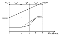
Fig. 8 is the example of figure of the principle that writes sequence of the related Nonvolatile semiconductor memory device of explanation present embodiment.
In the present embodiment, as shown in Figure 8, starting stage among writing sequence write circulation, be in the programming period P 1 of low-level threshold voltage vt h, establish each rising amplitude of passing through voltage Vpass that writes circulation less, in the programming period P 2 of high level threshold voltage, the rising Amplitude Ratio programming period P 1 of passing through voltage Vpass that makes each write circulation is large.In the situation that Fig. 8, in the end of period P 2, reach the maximum voltage Vpsmax that passes through by voltage Vpass.At this, the maximum voltage Vpsmax that passes through is such voltage Vpass that pass through, if that is: become greater to it by voltage Vpass more than, the potential difference (PD) of non-selection word line WL and raceway groove becomes large, the probability that non-select storage unit MC generation is write by mistake uprises.Therefore, if hypothesis make be elevated to it by voltage Vpass more than, be connected in non-selection word line WL and select the threshold voltage vt h of the non-select storage unit MC of bit line BL to change.Therefore, be set as and write circulation after lean on than period P 2, Vpass does not raise by voltage.
Thus, compare with comparative example shown in Figure 5, in period P 1, can suppress the increase of effective program voltage Vpgm.In addition, can prevent the change of low-level threshold voltage vt h, can suppress low-level threshold voltage vt h and enlarge.In addition, compare with comparative example shown in Figure 7, in period P 2, effectively program voltage Vpgm becomes higher, so the threshold voltage vt h of select storage unit MC easily changes desired threshold voltage vt h into, can shorten the processing time that writes sequence.
Next, describe about the control method that writes sequence shown in Figure 8.
Fig. 9 is by writing cycle index control by an example of the process flow diagram that writes sequence in the situation of the rising amplitude, ao Vpass of voltage Vpass.The work of process flow diagram is for example controlled by sequence control circuit 7.
At first, at step S201, will write period nl and be initialized as 1.In addition, will be initialized as initial by voltage Vpass be initially for example 5V by voltage Vpass0 by voltage Vpass0().
Next, at step S202, whether judgement writes period is that nl<Rnl1(Rnl1 is for example 10).If be the "Yes" of nl<Rnl1(S202), at step S203, with program voltage Vpgm, by voltage Vpass execution programing work.On the other hand, if be the "No" of nl 〉=Rnl1(S202), make to process and transfer to step S207.At this, write period and can be stored in the latch of NAND chip 10 interior configurations.
Next, at step S204, carry out verifying work.Suppose in the situation that in this step S204 whole storage unit all passed through (S204 " by "), power cut-off.On the other hand, in the situation that a part of storage unit is not passed through (S204 " failure "), at step S205, make to write period nl and increase progressively.
Next, at step S206, will be by voltage Vpass and Δ Vpass addition.At this, Δ Vpass is voltage Vc1.At this moment, make the program voltage Vpgm Δ Vpgm that also raises.After this, processing is turned back to step S202.
At step S207, with program voltage Vpgm, by voltage Vpass execution programing work.
Next, at step S208, carry out verifying work.Suppose in the situation that in this step S208 all storage unit all passed through (S208 " by "), power cut-off.On the other hand, in the situation that a part of storage unit is not passed through (S208 " failure "), at step S209, make to write period nl and increase progressively.
Next, at step S210, will be by voltage Vpass and Δ Vpass addition.At this, Δ Vpass is voltage Vc2(>voltage Vc1).At this moment, make the program voltage Vpgm Δ Vpgm that also raises.
Next, at step S211, whether judgement writes period nl is for example for example 15 for nl<Rnl2(Rnl2).If be the "Yes" of nl<Rnl2(S211), again at step S207, with program voltage Vpgm, by voltage Vpass execution programing work.On the other hand, if be the "No" of n 〉=Rnl2(S211), processing is transferred to step S212.In addition, Rnl1<Rnl2.
At step S212, with program voltage Vpgm, by voltage Vpass execution programing work.The voltage Vpass that passes through herein is the maximum voltage Vpsmax that passes through.That is to say, no longer make in programing work afterwards by voltage Vpass to raise.
Next, at step S213, carry out verifying work.Whether the judgement programming completes (whole storage unit are all passed through) in this verifying work, in the situation that complete (S213 " by "), finish to write sequence, in uncompleted situation (S213 " failure "), write period nl in step S214 judgement and whether reached maximum cycle (" largest loop " in figure).At this step S214, reach maximum cycle in the situation that write period nl, be made as and write failure and finish to write sequence.On the other hand, do not write cycle index in the situation that reach, processing is turned back to step S212.At this moment, program voltage Vpgm rising Δ Vpgm, but do not raise by voltage Vpass.
Figure 10 is by the example of program voltage Vpgm control by the process flow diagram that writes sequence in the situation of the rising amplitude, ao Vpass of voltage Vpass.The work of process flow diagram is for example controlled by sequence control circuit 7.
At first, at step S301, program voltage Vpgm is initialized as predetermined voltage Vpgm0(Vpgm0 for example is 13V).In addition, will be initialized as initial by voltage Vpass be initially for example 5V by voltage Vpass0 by voltage Vpass0().
Next, at step S302, judge whether program voltage Vpgm is that Vpgm<Rvpg1(Rvpg1 for example is 15V).If be the "Yes" of Vpgm<Rvpg1(S302), processing is transferred to step S303, if be the "No" of Vpgm 〉=Rvpg1(S302), processing is transferred to step S307.
Step S303 and S304 then, identical with step S203 and the S204 of Fig. 9, therefore description thereof is omitted.
Next, at step S305, the voltage Δ Vpgm that makes program voltage Vpgm raise and be scheduled to.After this, process the step S306 identical with the step S206 of Fig. 9, and processing is turned back to step S302.
Step S307 and S308 are identical with step S207 and the S208 of Fig. 9, and therefore description thereof is omitted.
Next, at step S309, make program voltage Vpgm boosted voltage Δ Vpgm.After this, process the step S310 identical with the step S210 of Fig. 9.
Next, at step S311, judge whether program voltage Vpgm is that Vpgm<Rvpg2(Rvpg2 for example is 17V).If be the "Yes" of Vpgm<Rvpg2(S311), again at step S307, with program voltage Vpgm, by voltage Vpass execution programing work.On the other hand, if be the "No" of Vpgm 〉=Rvpg2(step S311), processing is transferred to step S312.In addition, Rvpg1<Rvpg2.
Step S312~S314 and Fig. 9 step S212~S214 is identical, therefore description thereof is omitted.
Figure 11 is with the process flow diagram that writes sequence in the situation of controlling the rising amplitude, ao Vpass by voltage Vpass by voltage Vpass.The work of process flow diagram is for example controlled by sequence control circuit 7.
At first, at step S401, will be initialized as initial by voltage Vpass be initially for example 5V by voltage Vpass0 by voltage Vpasss0().
Next, at step S402, whether judgement is that Vpass<Rvpa1(Rvpa1 for example is 7V by voltage Vpass).If be the "Yes" of Vpass<Rvpa1(S402), processing is transferred to step S403, if be the "No" of Vpass 〉=Rvpa1(S402), processing is transferred to step S406.
Step S403, S404 and S405 then is identical with step S203, S204 and the S206 of Fig. 9, and therefore description thereof is omitted.
Step S406, S407 and S408 are identical with step S207, S208 and the S210 of Fig. 9, and therefore description thereof is omitted.
Next, at step S409, whether judgement is that Vpass<Rvpa2(Rvpa2 for example is 9V by voltage Vpass).If be the "Yes" of Vpass<Rvpa2(S409), again at step S406, carry out with program voltage Vpgm, by voltage Vpass and programme.On the other hand, if be the "No" of Vpass 〉=Rvpa2(S409), processing is transferred to step S410.In addition, Rvpa1<Rvpa2.
Step S410~S412 and Fig. 9 step S212~S214 is identical, therefore description thereof is omitted.
Next, be applied to use the situation of Nonvolatile semiconductor memory device of the storage unit of 2/unit to describe about the sequence that writes that present embodiment is related.For example, suppose the situation that the U page of Fig. 3 writes.
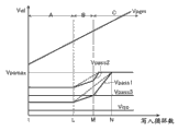
Figure 12 mean for the storage unit MC of 2/unit write sequence the time an example of the curve map that writes period and program voltage Vpgm and the relation by voltage Vpass.In addition, Figure 13 means the curve map that passes through voltage Vpass in the situation of Figure 12.
Writing of the 1st time~the L time (L being for example 5) of beginning circulates as during other programming of A level.At this, will be made as 0V by the rising amplitude, ao Vpass of voltage Vpass.
Writing of the L+1 time~the M time (M being for example 10) then circulates as during other programming of B level.At this, will be made as fixing voltage Vc1 by the rising amplitude, ao Vpass of voltage Vpass.
Then the M+1 time and later writing circulate as during other programming of C level.At this, will be made as by the rising amplitude, ao Vpass of voltage Vpass the fixing voltage Vc2 larger than voltage Vc1.In addition, in the situation that Figure 12 and Figure 13, the N time (N is for example 15) write circulation, will reach the maximum voltage Vpsmax that passes through by voltage Vpass.Therefore, if if at the N+1 time and later also make each boosted voltage Vc2 by voltage Vpass in writing circulation, the threshold voltage vt h that is applied in the non-select storage unit MC by voltage Vpass is also same when having applied program voltage Vpgm, can change.Therefore, at the N+1 time and later write circulation, do not make by voltage Vpass to raise.
As previously discussed, write sequence in present embodiment, conversion rising amplitude, ao Vpass makes rising amplitude, ao Vpass become large rear these 2 times with the circulation that writes of the M time that circulation is rear, other programming of B level will finish that writes of the L time that will finish in other programming of A level.
That is to say, in other words can be, if the voltage Vpass that passes through that will use in the n time writes circulation shows as Δ Vn with poor (the rising amplitude) of passing through voltage Vpass used in the n+1 time writes circulation, the data write section is to become Δ V(L-1)<Δ VL, Δ VL≤Δ V(M-1) and Δ V(M-1)<mode of Δ VM uses by voltage Vpass execution and writes circulation.
Like this, in the situation that Figure 12 and embodiment shown in Figure 13, during other programming of A level, by using low pass superpotential Vpass, can suppress other threshold value distribution of A level enlarges, and during the programming that the threshold voltage vt h such as B rank and/or C rank are difficult to change, can make by voltage Vpass according to its rank to raise, the threshold voltage vt h of storage unit MC is easily changed.
Next, the example about Figure 12 and the control method that writes sequence shown in Figure 13 describes.The work of process flow diagram is for example controlled by sequence control circuit 7.
Figure 14 is by writing cycle index nl control by an example of the process flow diagram that writes sequence in the situation of the rising amplitude, ao Vpass of voltage Vpass.At this, write period and can be stored in latch of NAND chip 10 interior configurations etc.
At first, at step S501, will write period nl and be initialized as 1.In addition, will be initialized as initial by voltage Vpass be initially for example 5V by voltage Vpass0 by voltage Vpass0().
Next, at step S502, judgement write period nl whether for nl<L(for example for example L be 5).If be the "Yes" of nl<L(S502), at step S503, with program voltage Vpgm, by voltage Vpass execution programing work.On the other hand, if be the "No" of nl 〉=L(S502), processing is transferred to step S507.
Next, at step S504, carry out verifying work.Suppose in the situation that in this step S504 whole storage unit all passed through (S504 " by "), power cut-off.On the other hand, in the situation that a part of storage unit is not passed through (S504 " failure "), at step S505, make to write period nl and increase progressively.
Next, at step S506, will be by voltage Vpass and Δ Vpass addition.But at this, Δ Vpass is 0V, does not in fact carry out any processing.That is to say, write period be nl<L during, Vpass does not raise by voltage.After this, processing is turned back to step S502.
At step S507, with program voltage Vpgm, by voltage Vpass execution programing work.
Next, at step S508, carry out verifying work.Suppose in the situation that in this step S508 whole storage unit all passed through (S508 " by "), power cut-off.On the other hand, in the situation that a part of storage unit is not passed through (S508 " failure "), make at step S509 to write period nl and increase progressively.
Next, at step S510, will be by voltage Vpass and Δ Vpass addition.At this, Δ Vpass is voltage Vc1.At this moment, make the program voltage Vpgm Δ Vpgm that also raises.
Next, at step S511, judgement write period nl whether for nl<M(for example for example M be 10).If be the "Yes" of nl<M(S511), again at step S507, with program voltage Vpgm, by voltage Vpass execution programing work.On the other hand, if be the "No" of nl 〉=M(S511), processing is transferred to step S512.
At step S512, with program voltage Vpgm, by voltage Vpass execution programing work.
Next, at step S513, carry out verifying work.Suppose in the situation that in this step S513 whole storage unit all passed through (S513 " by "), power cut-off.On the other hand, in the situation that a part of storage unit is not passed through (S513 " failure "), in step 514, make to write period nl and increase progressively.
Next, at step S515, will be by voltage Vpass and Δ Vpass addition.At this, Δ Vpass is voltage Vc2(>voltage Vc1).At this moment, make the program voltage Vpgm Δ Vpgm that also raises.
Next, at step S516, judgement write period nl whether for nl<N(for example for example N be 15).If be the "Yes" of nl<N(S516), again at step S512, with program voltage Vpgm, by voltage Vpass execution programing work.On the other hand, if be the "No" of nl 〉=N(S516), processing is transferred to step S517.
At step S517, use the maximum voltage Vpsmax that passes through to carry out programing work.
Next, at step S518, carry out verifying work.Whether the judgement programming completes (whole storage unit are all passed through) in this verifying work.In the situation that complete (S518 " by "), finish to write sequence, in uncompleted situation (S518 " failure "), write period nl in the S519 judgement and whether reached maximum cycle (" largest loop " in figure).At this step S519, reach maximum cycle in the situation that write period nl, be made as and write failure and finish to write sequence.On the other hand, do not write cycle index in the situation that reach, processing is turned back to step S517.At this moment, program voltage Vpgm rising Δ Vpgm, but do not raise by voltage Vpass.
The sequence that writes shown in Figure 14 is the situation of the rising amplitude, ao Vpass that passes through voltage Vpass of controlling by writing cycle index, but same with Figure 10 and Figure 11, also can control by program voltage Vpagm or by voltage Vpass.
In addition, in the situation that use the sequence that writes of present embodiment, can suppress as previously mentioned the expansion that low-level threshold value distributes, but also can obtain following effect in addition.
Figure 15 and Figure 16 are the examples that the curve map for Figure 12 makes figure overlapping during other programming of A rank ~ C level.Figure 15 is the few storage unit MC(of write/erase periodicity hereinafter referred to as " new (fresh) unit ") situation, Figure 16 is that the many storage unit MC(of write/erase periodicity are hereinafter referred to as " walking around to (cycled) unit ") situation.
In the situation that for the sequence that writes of new unit, as shown in figure 15, other is programmed in the A level writing in circulation of the L time (L being for example 5) and completes, other is programmed in the B level writing in circulation of the M time (L being for example 10) and completes, and other is programmed in the C level writing in circulation of the X time (X being for example 15) and completes.
With respect to this, in the situation that walk around to the unit, as shown in figure 16, the A level other be programmed in than the L time write the circulation Zao inferior the writing of L ' complete in circulation, other is programmed in the B level than Zao inferior the writing of M ' of circulation that write of the M time and completes in circulation, and other is programmed in the C level than the X time write Zao inferior the writing in circulation of X ' that circulate and completes.This is because usually, walk around to this side's threshold voltage of unit than new unit easily rise (below be sometimes referred to as " easily programming ").
That is to say, in the situation that Figure 15 and shown in Figure 16, during other programming of A level for new unit (the 1st time~the L time write circulation), become during other is programmed for the A rank that walks around to the unit and B level.It should be noted that so-called other programming of B level herein, even in walking around to the unit, also take the storage unit MC of easy programming as object.Similarly, during during other programming of the B level for new unit, (the L+1 time~the M time write circulation) becomes B rank for walking around to the unit and C level other programmes.It should be noted that so-called other programming of C level herein, even in walking around to the unit, also take the storage unit MC of easy programming as object.In addition, during other programming of the C level for new unit, (M later write circulation) is that C level for walking around to the unit is during other programmes.It should be noted that so-called other programming of C level herein, even in walking around to the unit, also take the storage unit MC that is difficult to programme as object.
As previously discussed, in the situation that Figure 12~sequence that writes shown in Figure 14, about walking around to the unit, the storage unit MC that easily carries out other programming of B level will suppress lowlyer by voltage Vpass, till do not raise the L time write circulation in be programmed, in addition, the storage unit MC that easily carries out other programming of C level the rising amplitude, ao Vpass by voltage Vpass be voltage Vc1 and till lower the M time write circulation in be programmed.As a result, can prevent from the B rank and the C level that walk around to the unit are else crossed programming.That is, present embodiment write sequence, can suppress to be enlarged by shown in the dotted line of Figure 17, upper root edge that B rank and other threshold value of C level distribute, the threshold value that can access solid line distributes.
Above, according to present embodiment, suppress by using the aforesaid sequence that writes, can not make the processing time that writes sequence to increase ground the expansion that low-level threshold value distributes.In addition, about the data that walk around to the unit are write, also can suppress the expansion that high level threshold value distributes.
[the 2nd embodiment ]
Below the 2nd~the 4th embodiment of explanation, be the variation of the 1st embodiment.
In the 2nd embodiment, about write circulation by each, the sequence that writes by the ground rising of voltage Vpass exponential function is described.
Figure 18 represent present embodiment related write sequence the time an example of the curve map that writes period and program voltage Vpgm and the relation by voltage Vpass.In addition, Figure 19 and Figure 20 mean and have used related the writing sequence and be set as the curve map of the situation of passing through voltage Vpass in the situation of N=6 of present embodiment.
In the situation that present embodiment as shown in figure 18, writes circulation until reach the maximum circulation that writes of the N time of passing through voltage Vpsmax by voltage Vpass rising amplitude, ao Vpass itself is raise and repeatedly carry out.This maximum is such voltage by voltage Vpsmax, if that is: make be elevated to it by voltage Vpass1 more than, the possibility that is connected in non-selection word line WL and selects the threshold voltage vt h of the non-select storage unit MC of bit line BL to change is high.In addition, mostly the initial voltage of program voltage Vpgm in the situation voltage of the 1st time (write period be) is higher by voltage Vpsmax than maximum.But program voltage Vpgm can either be made as identical by voltage Vpsmax with maximum, also can be made as lower by voltage Vpsmax than maximum.
Particularly, in the situation that shown in Figure 19, until reach the maximum circulation that writes of passing through the 6th time of voltage Vpsmax by voltage Vpass, make by the each 0.1V of increasing of the rising amplitude, ao Vpass of voltage Vpass itself and repeatedly execution write circulation.
That is to say, in other words can be, if will the n+1 time write circulation in use pass through voltage Vpass with respect to the n time write circulation in poor (the rising amplitude) of passing through voltage Vpass used show as Δ Vn, the data write section use become Δ V1=0.1V, Δ V2=0.2V,, the voltage Vpass that passes through of Δ V5=0.5V carries out and writes circulation.If represent it by general form, become Δ Vn=Δ V(n-1)+0.1.
In addition, Figure 20 is other examples that write sequence that present embodiment relates to.
In the situation that shown in Figure 20, the rising amplitude, ao Vpass that passes through voltage Vpass that writes circulation that is recycled to the 2nd time from the 1st time write is 0.1V, but after this, until reach by voltage Vpass the 6th time of lower limit of program voltage Vpgm write circulation till, make each 0.2V of increasing by the rising amplitude, ao Vpass of voltage Vpass itself, and execution writes circulation repeatedly.
The rising amplitude, ao Vpass of Figure 19 and Figure 20 controls, and can be undertaken by the computing that is realized by logical circuit.In addition, also can be worth to carry out by the change of the middle storage rising amplitude, ao Vpass such as the ROM fuse in NAND chip 10.
The easiness of the programming of storage unit MC is by each storage unit and heterogeneity also can't will demarcate during programmings at different levels sometimes clearly.
In this point, according to present embodiment, irrelevant with the threshold voltage of programming, storage unit MC for easy programming carries out the programing work that has used low pass superpotential Vpass, the storage unit MC that is difficult to programme is carried out the programing work that has used high pass superpotential Vpass, so compare with the 1st embodiment, can carry out optimal programing work according to the programming characteristic of storage unit.
[ the 3rd embodiment ]
In the 3rd embodiment, make in circulation by voltage Vpass about writing of stage in early days to raise with fixing amplitude, after this write circulation in the sequence that writes by the ground rising of voltage Vpass exponential function is described.
Figure 21 mean present embodiment related write sequence the time an example of the curve map that writes period and program voltage Vpgm and the relation by voltage Vpass.In addition, Figure 22 means used that present embodiment relates to write sequence and be set as the curve map of the relation of passing through voltage Vpass in the situation of L=2, N=6.
In the situation that present embodiment, as shown in figure 21, from the 1st time to the L time write circulation till, make by voltage Vpass with fixed amplitude Vc1 and raise, be recycled to the N time write from the L+1 time write the rising amplitude, ao Vpass itself by voltage Vpass is raise, and repeatedly carry out and write circulation.
Particularly, in the situation that shown in Figure 22, for example the 1st and the 2nd time write circulation, make the 0.1V that at every turn raises by voltage Vpass, be recycled to the 6th time writing circulation from the 3rd time write, make each 0.1V of increasing by the rising amplitude, ao Vpass of voltage Vpass itself, and execution writes circulation repeatedly.
That is to say, in other words, if will the n+1 time write circulation in use pass through voltage Vpass with respect to the n time write circulation in poor (the rising amplitude) of passing through voltage Vpass used show as Δ Vn, the data write section uses the voltage Vpass that passes through that becomes Δ V1=0.1V, Δ V2=0.1V, Δ V3=0.2V, Δ V4=0.3V, Δ V5=0.5V to carry out and write circulation.
In the situation that present embodiment, during the programming of low-level threshold voltage, due to the rising and the execution programing work that suppress by voltage Vpass, so same with the 1st embodiment, can suppress the expansion that low-level threshold value distributes, and after this write circulation, same with the 2nd embodiment, can carry out and use the programing work that pass through voltage Vpass that be fit to corresponding with the programming characteristic of storage unit.
[ the 4th embodiment ]
The 4th embodiment is different from writing of Fig. 3, in writing sequence, writes simultaneously being written as A ~ other storage unit of C level, begins to become in order and forbids write state (locking work) from having reached storage unit at different levels.This forbids write state, can be undertaken by the voltage (for example changing to 2.5V from 0V) of change bit line.
Figure 23 means that present embodiment relates to when writing sequence writes an example of the curve map of period and program voltage Vpgm and the relation by voltage Vpass.In addition, Figure 24 means the curve map that passes through voltage Vpass that has used in the situation that writes sequence that present embodiment relates to.At this, during other programming of A level be until be written as that the verification of other storage unit of A level passes through during, during other programming of B level be until be written as that the verification of other storage unit of B level passes through during, during other programming of C level be until be written as that the verification of other storage unit of C level passes through during.
In the situation that present embodiment, as shown in figure 23, as the 1st time~the L time during other programming of A level write circulation, do not make by voltage Vpass and carry out programing work with raising, as the L+1 time~the M time during other programming of B level write circulation, make by voltage Vpass raise and carry out programing work with the voltage Vc1 that is scheduled to.After this, as the M+1 time~the N time during other programming of C level write circulation, make by voltage Vpass exponential function ground raise and carry out programing work.
Particularly, in the situation that shown in Figure 24, writing circulation as the 1st time~the 4th during other programming of A level, do not make by voltage Vpass and carry out programing work with raising, as the 5th and the 6th time during other programming of B level write circulation, make by voltage Vpass rising 0.1V and carry out programing work.After this, as the 7th time~the 9th time during other programming of C level write circulation, make rising amplitude, ao Vpass itself the rising 0.1V and carry out programing work at every turn by voltage Vpass.
That is to say, if will the n+1 time write circulation in use pass through voltage Vpass with respect to the n time write circulation in poor (the rising amplitude) of passing through voltage Vpass used show as Δ Vn, the data write section uses becomes Δ V1~Δ V3=0V, Δ V4, Δ V5=0.1V, Δ V6=0.2V, Δ V7=0.3V, the voltage Vpass execution of passing through of Δ V8=0.4V writes circulation.
In the situation that present embodiment, during A rank and other programming of B level, same with the 1st embodiment, can carry out the programing work that is suitable for the threshold voltage that to programme, during other programming of C level, same with the 2nd embodiment, can carry out the programing work of the programming characteristic that is suitable for storage unit.
Figure 25 is that the ratio (hereinafter referred to as " verification percent of pass ") of the number of memory cells passed through as verification among the storage unit MC of programming object during by verifying work is controlled the process flow diagram that writes sequence in the situation of the rising amplitude, ao Vpass by voltage Vpass.In addition, the write sequence of the flowcharting of Figure 25 to the storage unit MC of 2/unit.At this, the verification percent of pass can be with the position that can be considered as passing through by the position that ECC corrects and the calculation check percent of pass.
At first, at step S601, judge whether other verification percent of pass of A level ra is that ra<Rra(Rra is for example 100%).If be ra<Rra, processing is transferred to step S602, if be ra 〉=Rra, processing is transferred to step S605.In addition, the verification percent of pass is not limited to 100%, during also can being defined as other programming of A level 70% moment of having passed through that is written as other storage unit of A level.Below, be also same about B rank, other verification percent of pass of C level.
Step S602 and S603 then is identical with step S203 and the S204 of Fig. 9, and therefore description thereof is omitted.In addition, at step S603, passed through to become in the storage unit programing work afterwards of other verification of A level and forbidden write state.
Next, at step S604, upgrade other verification percent of pass of A level ra based on the check results in step S603.After this, processing is back to step S601.
At step S605, judge whether other verification percent of pass of B level rb is that rb<Rrb(Rrb is for example 100%).If be rb<Rrb, processing is transferred to step S606.On the other hand, if be rb 〉=Rrb, processing is transferred to step S609.
Step S606 and S607 then is identical with step S207 and the S208 of Fig. 9, and therefore description thereof is omitted.
Next, at step S608, upgrade other verification percent of pass of B level rb based on the check results of step S607.After this, processing is back to step S605.
At step S609, whether judgement reaches the maximum voltage Vpsmax that passes through by voltage Vpass.In the situation that reach the maximum voltage Vpsmax that pass through by voltage Vpass, step S611 is transferred in processing, in the situation that pass through voltage Vpsmax by what voltage Vpass did not reach maximum, step S610 is transferred in processing.
Step S610, S611, S612 and S613 then is identical with step S207, S210, S211 and the S214 of Fig. 9, and therefore description thereof is omitted.
At last, at step S614, judge whether other verification percent of pass of C level rc is that rc<Rrc(Rrc is for example 100%).If be rc<Rrc, complete writing sequence.On the other hand, if be rc 〉=Rrc, write period nl in step S615 judgement and whether reached maximum cycle (" largest loop " in figure), on this basis processing is back to step S609.
Like this, for A ~ C rank, can both tackle in the mode that writes in the lump.As a result, can make the programing work high speed.
[ the 5th embodiment ]
The 5th embodiment is the variation of the 1st embodiment.
In the 1st embodiment, with the write/erase periodicity irrespectively, by writing period, program voltage Vpgm, changing rising amplitude, ao Vpass by voltage Vpass by voltage Vpass or verification percent of pass.But as mentioned above, usually, storage unit has along with the write/erase periodicity increases and the easily tendency of programming that becomes in the 1st embodiment.
Therefore, in the present embodiment, about according to the write/erase periodicity, the sequence that writes that changes the Rule of judgment that the rising amplitude, ao Vpass by voltage Vpass is changed describes.
Figure 26 is according to writing the circulation conversion part by the process flow diagram that writes sequence of the rising amplitude, ao Vpass of voltage Vpass, be process flow diagram shown in Figure 9 begin and step S201 between the processing that increases.
In the situation that Figure 26, at first at step S251, judge that whether the write/erase periodicity is greater than predetermined periodicity Rnc, in the situation that the write/erase number of times is less than or equal to periodicity Rnc, step S252 is transferred in processing, the benchmark that will use in the step S202 of Fig. 9 writes period Rnl1 and is initialized as predetermined period Cnl1, and the benchmark that will use in the step S206 of Fig. 9 writes period Rnl2 and is initialized as predetermined period Cnl2.On the other hand, in the situation that the write/erase periodicity is greater than predetermined periodicity Rnc, step S253 is transferred in processing, benchmark is write period Rnl1 be initialized as the period Cnl1 ' larger than period Cnl1, benchmark is write period Rnl2 be initialized as the period Cnl2 ' larger than period Cnl2.
In addition, this write/erase periodicity also can be stored in the interior ROM fuse of NAND chip 10.In the case, sequence control circuit 7 is read the write/erase periodicity of storing in the ROM fuse, carries out the processing of step S252.In addition, this write/erase periodicity also can be stored in ROM fuse 12.In the case, controller 11 also can be in the front and back that will write order and send to NAND chip 10, and the information of write/erase periodicity is sent to NAND chip 10.
Like this, be accompanied by the increase of write/erase periodicity, the rising by voltage Vpass is postponed, weaken thus assisting for the fast storage unit of program speed.Thus, can suppress to write the expansion that the threshold value after sequence distributes.
Figure 27 is according to the program voltage Vpgm conversion part by the process flow diagram that writes sequence of the rising amplitude, ao Vpass of voltage Vpass, be process flow diagram shown in Figure 10 begin and step S301 between the processing that increases.
In the situation that Figure 27, at first at step S351, judge that whether the write/erase periodicity is greater than predetermined periodicity Rnc, in the situation that the write/erase number of times is less than or equal to periodicity Rnc, step S352 is transferred in processing, the benchmark program voltage Rvpg1 that will use in the step S302 of Figure 10 is initialized as predetermined voltage Cvpg1, and the benchmark program voltage Rvpg2 that will use in the step S306 of Figure 10 is initialized as predetermined voltage Cvpg2.On the other hand, in the situation that the write/erase periodicity is greater than predetermined periodicity Rnc, step S353 is transferred in processing, benchmark program voltage Vpgm1 is initialized as the predetermined voltage Cvpg1 ' larger than voltage Cvpg1, benchmark program voltage Rvpg2 is initialized as the predetermined voltage Cvpg2 ' larger than voltage Cvpg2.
Figure 28 is according to by the voltage Vpass conversion part by the process flow diagram that writes sequence of the rising amplitude, ao Vpass of voltage Vpass, be process flow diagram shown in Figure 11 begin and step S401 between the processing that increases.
In the situation that Figure 28, at first at step S451, judge that whether the write/erase periodicity is greater than predetermined periodicity Rnc, in the situation that the write/erase periodicity is less than or equal to periodicity Rnc, step S452 is transferred in processing, the benchmark that will use in the step S402 of Figure 11 is initialized as predetermined voltage Cvpa1 by voltage Rvpa1, and the benchmark that will use in the step S406 of Figure 11 is initialized as predetermined voltage Cvpa2 by voltage Rvpa2.On the other hand, in the situation that the write/erase periodicity is greater than predetermined periodicity Rnc, step S453 is transferred in processing, benchmark is initialized as the predetermined voltage Cvpa1 ' larger than voltage Cvpa1 by voltage Vpga1, benchmark is initialized as the predetermined voltage Cvpa2 ' larger than voltage Cvpa2 by voltage Rvpa2.
Figure 29 means and writes sequence, the object lesson of an example of the relation of step S601, the S605 of write/erase cycle and process flow diagram shown in Figure 25 and the Rule of judgment of S614 at according to the verification percent of pass conversion rising amplitude, ao Vpass by voltage Vpass.
For example, in the situation that write/erase periodicity Rnc is less than 1000 times, be whether 100% to set the Rule of judgment of step S601 according to other verification percent of pass of A level, whether whether be 100% to set the Rule of judgment of step S605 according to other verification percent of pass of B level, be 100% to set the Rule of judgment of step S614 according to other verification percent of pass of C level.
In the situation that write/erase periodicity Rnc is less than 10,000 times, be whether 50% to set the Rule of judgment of step S601 according to other verification percent of pass of B level, whether whether be 50% to set the Rule of judgment of step S605 according to other verification percent of pass of B level, be 50% to set the Rule of judgment of step S614 according to other verification percent of pass of C level.
In addition, in the situation that write/erase periodicity Rnc is more than or equal to 10,000 times, be whether 75% to set the Rule of judgment of step S601 according to other verification percent of pass of B level, whether whether be 75% to set the Rule of judgment of step S605 according to other verification percent of pass of B level, be 100% to set the Rule of judgment of step S614 according to other verification percent of pass of C level.
Above, all same with Figure 25 in Figure 26~Figure 28, along with the increase of write/erase periodicity, the rising by voltage Vpass is postponed, can weaken thus assisting for the fast storage unit of program speed.Thus, can suppress to write the expansion that the threshold value after sequence distributes.
Above, according to present embodiment, not only can obtain the effect identical with the 1st embodiment, even and in the situation that programming characteristic changed because of the increase of write/erase periodicity, also can realize the rising of passing through voltage Vpass that is fit to, suppress the expansion that threshold value distributes.
[ the 6th embodiment ]
Data about Nonvolatile semiconductor memory device write, and use Fig. 3 and Fig. 4 to be illustrated in the 1st embodiment.In addition, enumerated data at use Fig. 5~Fig. 7 and write on the basis of fashionable problem points, by the 1st~the 5th embodiment, it has been solved.
But, write fashionablely in data, except the problems referred to above, also might produce following problem.That is to say, in the situation that for the data writing not of select storage unit MCi(i=0~n-1), in programing work, pairs of bit line BL applies for example supply voltage Vdd, by what is called boot (self-boost) thus the channel voltage that improves select storage unit MCi prevents the charge injection for the electric charge accumulating layer.At this moment, if the channel voltage of select storage unit MCi is low, the mistake that easily produces select storage unit MCi writes.
At this, the programing work of bootstrap approach (hereinafter referred to as " SB mode ") is described.
In the programing work of SB mode, at first the channel voltage with the NAND string is made as floating state, and non-selection word line WL is applied by voltage Vpass.If non-selection word line WL reaches by voltage Vpass soon, the channel voltage of NAND string rises.On this basis, to selecting word line WL to apply program voltage Vpgm.At this moment, the channel voltage of NAND string descends such as the leakages such as cut-off leakage because of junction leakage and/or selection gate transistor SG1 and SG2.After certain hour, transfer to the power cut-off that writes sequence from applying program voltage Vpgm.Select the voltage drop of word line WL and non-selection word line WL.In addition, also can after making the voltage of selecting word line WL temporarily drop to by voltage Vpass, descend together with non-selection word line WL.Thus, the channel voltage of NAND string descends because of the coupling with word line WL.Like this, in the programing work of SB mode, by the channel voltage bootstrapping (boost) that voltage Vpass makes NAND string of passing through of non-selection word line WL, the possibility occurrence that the mistake to the select storage unit MC that forbids writing is write reduces.
According to more than, in the Nonvolatile semiconductor memory device that present embodiment relates to, adopt the following sequence that writes.
The figure of the bias state of the memory cell array when Figure 30 means the programing work of present embodiment.
In the present embodiment, when programing work, to selecting word line WLi to apply program voltage Vpgm, the non-selection word line WLi-1 adjacent with selecting word line WLi and WLi+1 are applied by voltage Vpass1(the 1st pass through voltage), to other non-selection word line WL0~WLi-2 and WLi+2~WLn-1 apply by voltage Vpass2(the 2nd pass through voltage).At this, be to write by each the voltage that circulation raises by voltage Vpass1.In addition, also will be called " adjacent word line " by adjacent non-selection word line with selecting the word line below.
Figure 31 mean present embodiment write sequence the time an example of the curve map that writes period and program voltage and logical superpotential relation.
In the situation that present embodiment write sequence, write circulation in the programming of carrying out low-level threshold voltage vt h, to suppress littlely by the rising amplitude, ao Vpass of voltage Vpass1, the programming of carrying out high level threshold voltage vt h write circulation, the rising amplitude, ao Vpass1 by voltage Vpass1 is increased.On the other hand, regardless of writing circulation, all be made as the fixing voltage higher than the minimum that passes through voltage Vpass1 by voltage Vpass2.
In the situation that embodiment shown in Figure 31, rising amplitude, ao Vpass1 by voltage Vpass1, carry out the 1st time~the L time of other programming of A level write circulation in be 0V, carry out the L+1 time~the M time of other programming of B level write circulation in be Vc1(Vc1 0), carry out the M+1 time~the N time of other programming of C level write circulation in be Vc2(Vc2 Vc1), so become large.In addition, in the case, threshold voltage Vpass1 also is controlled to be can be more than or equal to maximum by voltage Vpsmax.By voltage Vpass2, substantially the starting stage that writes sequence of carrying out A rank, other programming of B level write circulation in become than by the high voltage of voltage Vpass1.
Next, describe about several control methods that write sequence shown in Figure 31.
Figure 32 is by writing cycle index control by an example of the process flow diagram that writes sequence in the rising amplitude, ao Vpass1 situation of voltage Vpass1.The work of process flow diagram is for example controlled by sequence control circuit 7.
At first at step S701, will write period nl and be made as 1(and carry out initialization).Program voltage Vpgm is made as initial programming voltage Vpgm0(Vpgm0 for example is 13V) (carrying out initialization).In addition, will be made as by voltage Vpass1 is initially for example 5V by voltage Vpass0(Vpass0) (carrying out initialization).
Next, at step S702, whether judgement writes period is that nl<Rnl1(Rnl1 is for example 10).If be the "Yes" of nl<Rnl1(step S702), make at step S703 to write period nl and increase progressively, afterwards at step S704, with program voltage Vpgm, carry out programing work by voltage Vpass1 and Vpass2.On the other hand, if be the "No" of nl 〉=Rnl1(step S702), processing is transferred to step S707.At this, write period nl and can be stored in the latch of NAND chip 10 interior configurations.In addition, write period nl and also can be stored in controller 11.In addition, write period nl and also can be stored in the ROM zone of not storing common data.
Next, at step S705, carry out verifying work.Suppose the situation that storage unit whole in this step S705 all passed through (step S705 " by "), power cut-off.On the other hand, in the situation that a part of storage unit is not passed through (step S705 " failure "), at step S706, will be by voltage Vpass1 and Δ Vpass1 addition.At this, Δ Vpass1 is voltage Vc1.At this moment, make the program voltage Vpgm Δ Vpgm that also raises.After this, processing is back to step S702.
Next, at step S707, whether judgement writes period nl is for example that nl<Rnl2(Rnl2 is for example 15).If be the "Yes" of nl<Rnl2(step S707), make at step S708 to write period nl and increase progressively, afterwards at step S709, with program voltage Vpgm, carry out programing work by voltage Vpass1 and Vpass2.On the other hand, if be the "No" of n 〉=Rnl2(step S707), processing is transferred to step S712.In addition, Rnl1<Rnl2.
Next, at step S710, carry out verifying work.Suppose in the situation that in this step S710 whole storage unit all passed through (step S710 " by "), power cut-off.On the other hand, in the situation that a part of storage unit is not passed through (step S710 " failure "), at step S711, will be by voltage Vpass1 and Δ Vpass1 addition.At this, Δ Vpass1 is voltage Vc2(>voltage Vc1).At this moment, make the program voltage Vpgm Δ Vpgm that also raises.
Next, at step S712, judgement writes period nl and whether reaches maximum cycle (" largest loop " in figure).At this step S712, reach maximum cycle in the situation that write period nl, be made as and write failure and finish to write sequence.On the other hand, do not reach maximum cycle in the situation that write period nl, make at step S713 to write period nl and increase progressively, afterwards at step S714, with program voltage Vpgm, carry out programing work by voltage Vpass1 and Vpass2.The voltage Vpass1 that passes through herein is the maximum voltage Vpsmax of passing through.That is to say, no longer make in programing work afterwards by voltage Vpass1 to raise.
Next, at step S715, carry out verifying work.Whether the judgement programming completes (whole storage unit are all passed through) in this verifying work, (S715 " by ") finishes to write sequence in the situation that complete, in uncompleted situation (S715 " failure "), make program voltage Vpgm rising Δ Vpgm at step S716, afterwards processing is turned back to step S712.In addition, at step S716, do not make by voltage Vpass1 to raise.
Figure 33 is by the example of program voltage Vpgm control by the process flow diagram that writes sequence in the situation of the rising amplitude, ao Vpass1 of voltage Vpass1.The work of process flow diagram is for example controlled by sequence control circuit 7.
The step S801 of beginning is identical with the step S701 of Figure 32, and therefore description thereof is omitted.
Next, at step S802, judge whether program voltage Vpgm is that Vpgm<Rvpg1(Rvpg1 for example is 15V).If be the "Yes" of Vpgm<Rvpg1(step S802), make at step S803 to write period nl and increase progressively, afterwards processing is transferred to step S804.On the other hand, if be the "No" of Vpgm 〉=Rvpg1(step S802), processing is transferred to step S808.
Step S804 then~S806 respectively with Figure 32 step S704~S706 is identical, therefore description thereof is omitted.
Next, at step S807, judgement writes period nl and whether has reached maximum cycle (" largest loop " in figure).At this step S807, reach maximum cycle in the situation that write period nl, be made as and write failure and finish to write sequence.On the other hand, do not reach maximum cycle in the situation that write period nl, processing is back to step S802.
Next, at step S808, judge whether program voltage Vpgm is that Vpgm<Rvpg2(Rvpg2 for example is 17V).If be the "Yes" of Vpgm<Rvpg2(step S808), make at step S809 to write period nl and increase progressively, afterwards processing is transferred to step S810.On the other hand, if be the "No" of Vpgm 〉=Rvpg2(step S808), processing is transferred to step S814.In addition, Rvpg1<Rvpg2.
Step S810 then~S812 and Figure 32 step S709~S711 is identical, so description thereof is omitted.
Step S814 then~S817 and Figure 32 step S713 ~ S716 is identical, so description thereof is omitted.
Like this, control the rising amplitude, ao Vpass1 that passes through voltage Vpass1 by program voltage Vpgm, can improve the channel voltage of select storage unit thus when program voltage Vpgm is high.Its result can prevent accurately that the mistake of storage unit from writing.
In addition, in the situation that the sequence that writes is as shown in figure 33 controlled rising amplitude, ao Vpass1 by voltage Vpass1 by program voltage Vpgm like that, setting steps S807, S813 and S818 are arbitrarily.In the situation that be provided with step S807, S813 and S818 as the example of Figure 33, the period nl that writes take finish time that writes circulation of step S806, S812 and S817 reaches certain and writes period as condition, can be made as immediately write failure and finish to write sequence.
On the other hand, in the situation that omitted step S807, S813 and S818, due to the management that does not need to write period nl, so circuit structure is simplified.
Figure 34 is the example with the process flow diagram that writes sequence in the situation of controlling the rising amplitude, ao Vpass1 by voltage Vpass1 by voltage Vpass1.The work of process flow diagram is for example controlled by sequence control circuit 7.
The step S901 of beginning is identical with the step S701 of Figure 32, and therefore description thereof is omitted.
Next, at step S902, whether judgement is that Vpass1<Rvpa1(Rvpa1 for example is 7V by voltage Vpass1).If be the "Yes" of Vpass1<Rvpa1(step S902), make at step S903 to write period nl and increase progressively, afterwards processing is transferred to step S903.On the other hand, if be the "No" of Vpass1 〉=Rvpa1(step S902), processing is transferred to step S908.
Step S904 then~S907 respectively with Figure 33 step S804~S807 is identical, therefore description thereof is omitted.
Next, at step S908, whether judgement is that Vpass1<Rvpa2(Rvpa2 for example is 9V by voltage Vpass1).If be the "Yes" of Vpass1<Rvpa2(S908), make at step S909 to write period nl and increase progressively, afterwards processing is transferred to step S910.On the other hand, if be the "No" of Vpass1 〉=Rvpa2(S908), processing is transferred to step S914.In addition, Rvpa1<Rvpa2.
Step S910 then~S918 and Figure 33 step S810~S818 is identical, so description thereof is omitted.
In addition, in the situation that as shown in figure 34 write sequence like that controlling the rising amplitude, ao Vpass1 by voltage Vpass1 by voltage Vpass1, setting steps S907, S913 and S918 are arbitrarily.In the situation that be provided with step S907, S913 and S918 as the example of Figure 34, the period that writes take finish time that writes circulation of step S906, S912 and S917 reaches certain and writes circulation as condition, can be made as immediately to write failure and finish to write sequence.
On the other hand, in the situation that omitted step S907, S913 and S918, due to the management that does not need to write period nl, so circuit structure is simplified.
In addition, by to control by voltage Vpass1, regardless of program voltage Vpgm, can both control rising amplitude, ao Vpass1.For example, in the situation that according to the deteriorated initial voltage that reduces program voltage Vpgm of storage unit, the rising by voltage Vpass1 begins and can postpone.Its result, having mistiming to write can increase.On the other hand, few according to the deteriorated situation about changing of storage unit by voltage Vpass1.Its result can begin the rising by voltage Vpass1 to set suitablely, can prevent that mistake from writing.
Figure 35 is that the ratio (hereinafter referred to as " verification percent of pass ") of the number of memory cells passed through as verification among the storage unit MC of programming object during by verifying work is controlled the process flow diagram that writes sequence in the situation of the rising amplitude, ao Vpass1 by voltage Vpass1.The work of process flow diagram is for example controlled by sequence control circuit 7.In addition, about the position that can be corrected by ECC, the position that also can be considered as passing through and calculation check percent of pass.
The step SA01 of beginning is identical with the step S701 of Figure 32, and therefore description thereof is omitted.
Next, at step SA02, judge whether other verification percent of pass of A level ra is that ra 〉=Rra(Rra is for example 100%).If be the "No" of ra<Rra(step SA02), make at step SA03 to write period nl and increase progressively, afterwards at step SA04, with program voltage Vpgm, carry out programing work by voltage Vpass1 and Vpass2.At this, Δ Vpass1 is for example 0V.On the other hand, if be the "Yes" of ra 〉=Rra(step SA02), processing is transferred to step SA09.In addition, the verification percent of pass is not limited to 100%, during also can being defined as other programming of A level 70% moment of having passed through that is written as other storage unit of A level.Below, be also same about B rank, other verification percent of pass of C level.
Next, at step SA05, carry out verifying work.In addition, at step SA05, passed through to become in the storage unit programing work afterwards of other verification of A level and forbidden write state.
Next, at step SA06, upgrade other verification percent of pass of A level ra based on the check results of step SA05.
Step SA07 and SA08 then, identical with step S807 and the S808 of Figure 33 except the rising amplitude by voltage Vpass1 is Δ Vpass1=0, therefore description thereof is omitted.
Next, at step SA09, judge whether other verification percent of pass of B level rb is that rb 〉=Rrb(Rrb is for example 100%).If be the "No" of rb<Rrb(step SA09), make at step SA10 to write period nl and increase progressively, afterwards at step SA11, with program voltage Vpgm, carry out programing work by voltage Vpass1 and Vpass2.At this, Δ Vpass1 is voltage Vc1.On the other hand, if be the "Yes" of rb 〉=Rrb(step SA09), processing is transferred to step SA16.
Next, at step SA12, carry out verifying work.In addition, at step SA12, passed through to become in the storage unit programing work afterwards of other verification of B level and forbidden write state.
Next, at step SA13, upgrade other verification percent of pass of B level rb based on the check results in step SA12.
Step SA14 and SA15 then, identical with step S806 and the S807 of Figure 33 except by the rising amplitude, ao Vpass1=Vc1 of voltage Vpass1, therefore description thereof is omitted.
Next, at step SA16, judge whether other verification percent of pass of C level rc is that rc 〉=Rrc(Rrc is for example 100%).If be the "Yes" of rc 〉=Rrc(step SA16), finish to write sequence.On the other hand, if be the "No" of rc<Rrc(step SA16), make at step SA17 to write period nl and increase progressively, afterwards processing is transferred to step SA18.
Next, at step SA18, whether judgement reaches maximum by voltage Vpsmax by voltage Vpass1.In the situation that reach maximum by voltage Vpsmax ("Yes" of step SA18) by voltage Vpass1, at step SA19, will be made as Vpass1=Vc2 by the rising amplitude of voltage Vpass1 and carry out programing work.On the other hand, in the situation that do not reach maximum by voltage Vpsmax ("No" of step SA18) by voltage Vpass1, at step SA20, will be made as Vpass1=Vpsmax and carry out programing work by voltage.
Next, at step SA21, carry out verifying work.In addition, at step SA21, passed through to become in the storage unit programing work afterwards of other verification of C level and forbidden write state.
Next, at step SA22, upgrade other verification percent of pass of C level rc based on the check results in step SA21.
Step SA23 and SA24 then, identical with step S806 and the S807 of Figure 33 except the rising amplitude by voltage Vpass1 is Δ Vpass1=Vc2, therefore description thereof is omitted.
Like this, control by verification percent of pass ra, rb or rc the rising amplitude, ao Vpass1 that passes through voltage Vpass1, thus can be according to each rank adjusting by voltage Vpass1.Its result, the amplitude that threshold values can refinement at different levels distribute.
In addition, in the situation that the sequence that writes is as shown in figure 35 controlled rising amplitude, ao Vpass1 by voltage Vpass1 by verification percent of pass ra, rb or rc like that, setting steps SA08, SA15 and SA24 are arbitrarily.In the situation that be provided with step SA08, SA15 and SA24 as the example of Figure 35, the period nl that writes that writes circulation finish time take step SA07, SA14 and SA23 reaches certain and writes circulation as condition, can be made as immediately to write failure and finish to write sequence.
On the other hand, in the situation that omitted step S807, S813 and S818, due to the management that does not need to write period nl, so circuit structure is simplified.
As previously discussed, larger to a certain extent by voltage Vpass2 in the starting stage that writes sequence according to the sequence that writes of present embodiment, therefore same with the situation of the programing work of in the past use SB mode, channel voltage is booted fully.The possibility occurrence that thus, the mistake to the select storage unit forbidding writing is write is lower.On the other hand, Vpass2 fixes by voltage, even therefore also can be not too high by voltage Vpass2 at the later stage that writes sequence.Thus, also can reduce the possibility occurrence that the mistake that is connected in the non-select storage unit of selecting bit line is write.
And then, compare with the situation of the programing work of in the past use SB mode, in the starting stage that writes sequence, will be with selecting the word line voltage Vpass1 that passes through of adjacent non-selection word line suppress lowlyer.Its result can reduce the voltage that the bootstrap effect that caused by adjacent word line causes and rise.That is to say, can suppress to select the increase of effective program voltage Vpgm of word line.Thus, the change of the low-level threshold voltage (for example A rank, B rank) of select storage unit can be prevented, the expansion of the low-level threshold value distribution of storage unit group can be suppressed.In addition, writing the later stage of sequence (for example the threshold voltage with storage unit is written as other situation of C level), rising amplitude by voltage Vpass1 becomes large, therefore can further improve effective program voltage Vpgm of the selection word line that is caused by bootstrap effect.Thus, the escalating rate of the threshold voltage of the select storage unit that makes the threshold voltage rising can be increased, the processing time that writes sequence can be shortened.
In addition, by voltage Vc1 is made as 0, can suppress the expansion that the threshold value of the low-level threshold voltage (particularly A rank) of select storage unit distributes.
Next, the variation that writes sequence about present embodiment describes.
Figure 36 mean present embodiment write sequence the time an example of the curve map that writes period and program voltage and logical superpotential relation.In this variation, write circulation by each and make by the ground rising of voltage Vpass1 exponential function.
At this, the rising of so-called exponential function, finger will the n+1 time write circulation in use pass through voltage Vpass1 with respect in the situation that the n time write circulation in poor (the rising amplitude) of passing through voltage Vpass1 used be made as Δ Vn, the rising amplitude is by Δ Vn=Δ V(n-1)+situation of 0.1 expression.
There is heterogeneity in the easiness of the rising of the threshold voltage of storage unit MC by each storage unit MC, sometimes also can't will demarcate clearly during programmings at different levels.But, in the situation that this variation, irrelevant with the threshold voltage of programming, the storage unit MC that easily rises for threshold voltage carries out the programing work that has used low pass superpotential Vpass, and the storage unit MC that threshold voltage is difficult to rise carries out the programing work that has used high pass superpotential Vpass.Therefore, compare with the embodiment shown in Figure 31 of present embodiment, can carry out the optimal programing work of the programming characteristic that further accords with storage unit MC.
Above, according to present embodiment, with in the past use the situation of programing work of SB mode same, the Nonvolatile semiconductor memory device of the expansion that the threshold value that can provide the possibility occurrence that not only can reduce the mistake to the select storage unit forbidding writing and write, has also suppressed the storage unit group distributes.
[ the 7th embodiment ]
In the 6th embodiment, Nonvolatile semiconductor memory device about the programing work that used the SB mode is illustrated, but in the 7th embodiment, describe about the Nonvolatile semiconductor memory device of the programing work that used so-called erase area bootstrap approach (hereinafter referred to as " EASB mode ").In addition, about unaccounted aspect, identical with the 1st embodiment.
The example of the figure of the bias state of the memory cell array when Figure 37 means the programing work of present embodiment, Figure 38 mean present embodiment write sequence the time an example of the curve map that writes period and program voltage and logical superpotential relation.In addition, Figure 37 and Figure 38 supposition is from the situation of the storage unit MC data writing of source line CELSRC side.
The threshold voltage of storage unit writes by data and improves.Therefore, the channel voltage of the storage unit after data write is difficult to rise by bootstrapping, the bootstrapping decrease in efficiency.
Therefore, in the programing work of EASB mode, the raceway groove electricity of the storage unit before raceway groove and the data that comprise select storage unit by the storage unit after data are write write separates, and the channel voltage of select storage unit is easily booted.
Particularly, as shown in figure 37, to selecting word line WLi to apply program voltage Vpgm, the non-selection word line WL adjacent with the source line CELSRC side of selecting word line WLi applied separation voltage Viso, the adjacent word line WLi+ 1 of the bit line BL side of selecting word line WLi is applied by voltage Vpass1(the 1st pass through voltage), non-selection word line WL0~WLi-2 is applied by voltage Vpass3(the 3rd passes through voltage), non-selection word line WLi+2~WLn-1 is applied by voltage Vpass2(the 2nd pass through voltage).
At this, by voltage Vpass2 as shown in figure 38, how write circulation all for fixing voltage, be the voltage higher than the minimum of program voltage Vpgm.In addition, by voltage Vpass3 as shown in figure 38, write circulation and how all to be fixing voltage.And separation voltage Viso as shown in figure 38, is how to write circulation for fixing voltage, is for example slightly high than ground voltage Vss voltage.
On the other hand, same with the 6th embodiment by voltage Vpass1, be to increase as the upper limit and along with writing circulation the voltage that raises by voltage Vpsmax take maximum.That is to say, by voltage Vpass1 as shown in figure 38, following voltage: initial value is made as than passing through the low voltage of voltage Vpass3, rising amplitude, ao Vpass1 carry out the 1st time~the L time of other programming of A level write circulation in be 0V, carry out the L+1 time~the M time of other programming of B level write circulation in become greatly Vc1(Vc2 Vc1), carry out the M+1 time~the N time of other programming of C level write circulation in become greatly Vc2(Vc2 Vc1).
As previously discussed, by word line WLi – 1 is applied separation voltage Viso, the channel cutoff of storage unit MCi – 1, the raceway groove electricity of the storage unit MCi before raceway groove and the data of storage unit MC0 after data write~MCi-2 are write~MCn – 1 separates.In addition, below, the non-selection word line that sometimes also will be applied in separation voltage Viso is called " separate and use the word line ".
On this basis, by word line WL0~WLi-2 being applied the lower voltage Vpass3 that passes through, the storage unit MC0 after writing about data~MCi-2 can reduce because of the excessive logical superpotential possibility occurrence that the mistake that causes writes that applies.
On the other hand, word line WLi+1~WLn-1 is applied the higher voltage Vpass2 that passes through, therefore be not subjected to the impact of storage unit MC0~MCi-2, the channel voltage bootstrapping of the storage unit MCi before data are write~MCn-1.Its result can reduce the possibility occurrence that the mistake to the select storage unit MCi that forbids writing writes.
That is to say, according to Figure 37 of present embodiment and embodiment shown in Figure 38, not only have the effect identical with Figure 30 of the 6th embodiment and embodiment shown in Figure 31, and and then can further reduce the possibility occurrence that the mistake to the select storage unit forbidding writing writes.
In addition, as shown in figure 39, by non-selection word line WLi, the WLi+2 adjacent with the both sides of selecting word line WLi+ 1 are applied by voltage Vpass1, can effectively suppress the expansion of the threshold value distribution of storage unit group.
Next, the several of the variation that writes sequence about present embodiment describe.
The 1st variation is the example of controlling as shown in figure 40 each voltage shown in Figure 37.Figure 40 mean present embodiment write sequence the time the curve map that writes period and program voltage and logical superpotential relation.
In this variation, different from the embodiment that makes Figure 37 and Figure 38 combination of present embodiment, make by voltage Vpass2 take maximum by voltage Vpsmax as the upper limit, increase and raise along with writing circulation.Like this, in the present embodiment, not only make by voltage Vpass1 to raise, and can make by voltage Vpass2 and raise.Raise by making by voltage Vpass2 like this, can further make channel voltage increase.
In addition, as shown in figure 40, the timing that changes by the rising amplitude, ao Vpass2 that makes by voltage Vpass2 is consistent with the timing that the rising amplitude, ao Vpass1 that makes by voltage Vpass1 changes, can make by the needed parameter of the control of voltage Vpass2 with by voltage Vpass1 identical, also can make the control of passing through voltage Vpass2 of being undertaken by the data write section become easy.
The 2nd variation is to control as shown in Figure 41 the example of each voltage shown in Figure 37.Figure 41 mean present embodiment write sequence the time the curve map that writes period and program voltage and logical superpotential relation.
In this variation, different from the embodiment that makes Figure 37 and Figure 38 combination of present embodiment, make by voltage Vpass1 take maximum by voltage Vpsmax as the upper limit, increase and exponential function ground rising along with writing circulation.That is to say, in the situation that this variation, have nothing to do with the threshold voltage of programming, the storage unit MC execution of easy programming has been used the programing work of low pass superpotential Vpass1, the storage unit MC that is difficult to programme is carried out the programing work that has used high pass superpotential Vpass1.
Therefore, according to this variation, compare with the embodiment that makes Figure 37 and Figure 38 combination of present embodiment, can carry out the optimal programing work of the programming characteristic that accords with storage unit.
The 3rd variation is to control as shown in Figure 42 the example of each voltage shown in Figure 38.The figure of the bias state of the memory cell array when Figure 42 means the programing work of present embodiment.
In this variation, different from the embodiment that makes Figure 37 and Figure 38 combination of present embodiment, not only the non-selection word line WLi-1 adjacent with the source line CELSRC side of selecting word line WLi use the word line as separating, and and then non-selection word line WLi-2 that it is adjacent also as separation word line.
Be 1 in the situation that separate with word line WL as the embodiment that makes Figure 37 and Figure 38 combination of present embodiment, the raceway groove of the storage unit MC after sometimes can not fully data being write separates with the raceway groove electricity that data write front storage unit MC.In this point, according to this variation, be many owing to separating with word line WL, so compare with the embodiment that makes Figure 37 and Figure 38 combination of present embodiment, the raceway groove of the storage unit MC after can more effectively data being write separates with the raceway groove electricity that data write front storage unit MC.
[ the 8th embodiment ]
In the 7th embodiment, Nonvolatile semiconductor memory device about the programing work that used the EASB mode is illustrated, but in the 8th embodiment, describe about the Nonvolatile semiconductor memory device of the programing work of the erase area bootstrap approach (hereinafter referred to as " REASB mode ") that used revision.In addition, about unaccounted aspect, identical with the 7th embodiment.
Figure 43 means the figure of the bias state of the memory cell array in the programing work of present embodiment, Figure 44 mean present embodiment write sequence the time the curve map that writes period and program voltage and logical superpotential relation.In addition, Figure 43 and Figure 44, take from the storage unit MC of source line CELSRC side sequentially data writing as prerequisite.
In the situation that used the programing work of EASB mode, with regard to the example of Figure 37, can produce large potential difference (PD) being connected between the raceway groove that separates with the raceway groove of the storage unit MCi-1 of word line WLi-1 and the storage unit MCi-2 adjacent with this storage unit MCi-1 or storage unit MCi.In this situation, discharge the electronics that has accelerated towards storage unit MCi-2 or storage unit MCi from the raceway groove of storage unit MCi-1.And in the situation that this electronics has entered the floating grid of storage unit MCi-2 or MCi, the mistake that can produce storage unit MCi-2 or MCi writes.
At this, in the programing work of REASB mode, to separate non-selection word line with adjacent one or both of word line and apply separation voltage and program voltage or logical superpotential medium voltage and namely relax voltage.
particularly, as shown in figure 43, to selecting word line WLi to apply program voltage Vpgm, adjacent word line WLi-1 and WLi+1 are applied by voltage Vpass1(the 1st pass through voltage), non-selection word line WLi-3 to the source line CELSRC side of selecting word line WLi applies separation voltage Viso, to relaxing voltage Vgp with separating to apply with the adjacent non-selection word line WLi-4 of word line WLi-3 and WLi-2, non-selection word line WLi+2~WLn – 1 is applied by voltage Vpass2(the 2nd and passes through voltage), non-selection word line WL0~WLi – 5 is applied by voltage Vpass3(the 3rd and passes through voltage).
For example, relax voltage Vgp as shown in figure 44, to write circulation how all to be fixing voltage, be than program voltage Vpgm minimum, by the minimum of voltage Vpass1, by voltage Vpass2 or by low and higher than the separation voltage Viso voltage of voltage Vpass3.In addition, program voltage Vpgm, identical with embodiment shown in Figure 38 by voltage Vpass1, Vpass2 and Vpass3 and separation voltage Viso.In addition, sometimes also will apply the non-selection word line that relaxes voltage Vgp and be called " relax and use the word line ".In addition, by word line WLi-1, the WLi+1 adjacent with the both sides that select word line WLi are applied by voltage Vpass1, can effectively suppress the expansion of the threshold value distribution of storage unit group.
As previously discussed, by to relaxing voltage Vgp with separating to apply with the adjacent non-selection word line WLi-2 of word line WLi-3 and WLi – 4, can reduce from the acceleration towards the electronics of storage unit MCi-4 and MCi-2 of the raceway groove of storage unit MCi-3.Therefore, this electronics enters the possibility step-down of the electric charge accumulating layer of storage unit MCi-4 and MCi-2.
That is to say, the embodiment that makes Figure 43 and Figure 44 combination according to present embodiment, not only have the effect identical with the embodiment that makes Figure 37 and Figure 38 combination of the 7th embodiment, but also can further reduce missing the possibility occurrence that writes with being connected in to separate with the adjacent storage unit of the storage unit of word line.
Next, the several of the variation that writes sequence about present embodiment describe.
The 1st variation is to control as shown in Figure 45 the example of each voltage shown in Figure 43.Figure 45 mean present embodiment write sequence the time an example of the curve map that writes period and program voltage and logical superpotential relation.
In this variation, different from the embodiment that makes Figure 43 and Figure 44 combination of present embodiment, make by voltage Vpass2 take maximum by voltage Vpsmax as the upper limit, increase and raise along with writing circulation.Like this, in the present embodiment, not only make by voltage Vpass1 to raise, and can make by voltage Vpass2 and raise.
The 2nd variation is the example of controlling as shown in Figure 46 each voltage shown in Figure 43.Figure 46 mean present embodiment write sequence the time the curve map that writes period and program voltage and logical superpotential relation.
In this variation, different from the embodiment that makes Figure 43 and Figure 44 combination of present embodiment, make by voltage Vpass1 take maximum by voltage Vpsmax as the upper limit, increase and exponential function ground rising along with writing circulation.
Therefore, according to this variation, compare with the embodiment that makes Figure 43 and Figure 44 combination of present embodiment, can carry out the optimal programing work of the programming characteristic that accords with storage unit.
The 3rd variation is the example of controlling as shown in Figure 47 each voltage shown in Figure 43.The figure of the bias state of the memory cell array when Figure 47 means the programing work of present embodiment.
In this variation, different from the embodiment that makes Figure 43 and Figure 44 combination of present embodiment, not only the non-selection word line WLi-3 adjacent with the source line CELSRC side of selecting word line WLi use the word line as separating, and and then non-selection word line WLi-4 that it is adjacent also as separation word line.
Therefore, according to this variation, compare with the embodiment that makes Figure 43 and Figure 44 combination of present embodiment, the raceway groove of the storage unit MC after can more effectively data being write separates with the raceway groove electricity that data write front storage unit MC.
[ the 9th embodiment ]
In the 7th embodiment, Nonvolatile semiconductor memory device about the programing work that used the EASB mode is illustrated, but in the 9th embodiment, describe about the Nonvolatile semiconductor memory device of the programing work that used so-called local bootstrap approach (hereinafter referred to as " LSB mode ").In addition, about unaccounted aspect, identical with the 7th embodiment.
The example of the figure of the bias state of the memory cell array when Figure 48 means the programing work of present embodiment.In addition, Figure 48 supposition is from the situation of the storage unit MC data writing of source line CELSRC side.
In the situation that used the programing work of EASB mode, raceway groove by the storage unit after data are write separates with the raceway groove electricity that data write front storage unit, compare with the situation of the programing work that has used the SB mode, can make more efficiently the channel voltage supercharging of select storage unit.
With respect to this, in the programing work of LSB mode, the raceway groove of select storage unit is not only separated with the source line CELSRC side of select storage unit but also with the raceway groove electricity of the storage unit of bit line BL side.Thus, compare with the situation of the programing work that has used the EASB mode, can make more efficiently the channel voltage supercharging of select storage unit.
particularly, as shown in figure 48, to selecting word line WLi to apply program voltage Vpgm, adjacent word line WLi-1 and WLi+1 are applied by voltage Vpass1(the 1st pass through voltage), the non-selection word line WLi-2 adjacent with the source line CELSRC side of adjacent word line WLi – 1 and the non-selection word line WLi+ 2 adjacent with the bit line BL side of adjacent word line WLi+ 1 are applied by voltage Vpass2(the 2nd pass through voltage), the non-selection word line WLi-3 adjacent with the source line CELSRC side of non-selection word line WLi-2 and the non-selection word line WLi+ 3 adjacent with the bit line BL side of non-selection word line WLi+ 2 are applied separation voltage Viso, other non-selection word line WL0~WLi-4 and WLi+4~WLn-1 are applied by voltage Vpass3(the 3rd pass through voltage).
At this, with respect to the program voltage Vpgm that writes circulation, control by voltage Vpass1~Vpass3 and separation voltage Viso, identical with embodiment shown in Figure 38.
As previously discussed, in the situation that the embodiment that makes Figure 38 and Figure 48 combination of present embodiment, by making non-select storage unit MCi-3 and MCi+3 cut-off, the raceway groove of select storage unit MCi periphery can be separated with the raceway groove electricity of other non-select storage unit MC.
Thus, the embodiment that makes Figure 38 and Figure 48 combination according to present embodiment, not only have the effect same with the embodiment that makes Figure 37 and Figure 38 combination of the 7th embodiment, and further, the mistake that can more reduce the select storage unit forbidding writing writes.
Next, the several of the variation that writes sequence about present embodiment describe.
The 1st variation is the example of controlling as shown in Figure 40 each voltage shown in Figure 48.
In this variation, different from the embodiment that makes Figure 38 and Figure 48 combination of present embodiment, make by voltage Vpass2 take maximum by voltage Vpsmax as the upper limit, increase and raise along with writing circulation.Like this, in the present embodiment, not only make by voltage Vpass1 to raise, and can make by voltage Vpass2 and raise.
The 2nd variation is the example of controlling as shown in Figure 41 each voltage shown in Figure 48.
In this variation, different from the embodiment that makes Figure 38 and Figure 48 combination of present embodiment, make by voltage Vpass1 take maximum by voltage Vpsmax as the upper limit, increase and exponential function ground rising along with writing circulation.
Therefore, according to this variation, compare with the embodiment that makes Figure 38 and Figure 48 combination of present embodiment, can carry out the optimal programing work of the programming characteristic that accords with storage unit.
The 3rd variation is the example of controlling as shown in Figure 49 each voltage shown in Figure 48.The figure of the bias state of the memory cell array when Figure 49 means the programing work of present embodiment.
In this variation, different from the embodiment that makes Figure 38 and Figure 48 combination of present embodiment, not only the non-selection word line WLi-3 adjacent with the source line CELSRC side of selecting word line WLi use the word line as separating, and and then also non-selection word line WLi-4 that it is adjacent also as separation word line.
Therefore, according to this variation, compare with the embodiment that makes Figure 38 and Figure 48 combination of present embodiment, can be more effectively the raceway groove of select storage unit MC periphery be separated with the raceway groove electricity of other non-select storage units.
[ the 10th embodiment ]
In the 8th embodiment, Nonvolatile semiconductor memory device about the programing work that used the REASB mode is illustrated, but in the 10th embodiment, describe about the Nonvolatile semiconductor memory device of the programing work that used the local bootstrap approach of so-called revision (hereinafter referred to as " RLSB mode ").In addition, about unaccounted point, identical with the 8th embodiment.
The figure of the bias state of the memory cell array when Figure 50 means the programing work of present embodiment.In addition, Figure 50 take from the storage unit MC of source line CELSRC side sequentially data writing as prerequisite.
In the situation that used the programing work of REASB mode, raceway groove by the storage unit after data are write separates with the raceway groove electricity that data write front storage unit, compare with the situation of the programing work that has used the SB mode, the channel voltage of select storage unit is raise.
With respect to this, in the programing work of RLSB mode, the raceway groove of select storage unit is not only separated with the source line CELSRC side of select storage unit but also with the raceway groove electricity of the storage unit of bit line BL side.Thus, compare with the situation of the programing work that has used the EASB mode, can make more efficiently the raceway groove supercharging of select storage unit.
particularly, as shown in figure 50, to selecting word line WLi to apply program voltage Vpgm, adjacent word line WLi-1 and WLi+1 are applied by voltage Vpass1(the 1st pass through voltage), the non-selection word line WLi-2 adjacent with the source line CELSRC side of adjacent word line WLi-1 and the non-selection word line WLi+ 2 adjacent with the bit line BL side of adjacent word line WLi+ 1 are applied by voltage Vpass2(the 2nd pass through voltage), the non-selection word line WLi-3 adjacent with the source line CELSRC side of non-selection word line WLi-2 and the non-selection word line WLi+ 3 adjacent with the bit line BL side of non-selection word line WLi+ 2 are applied separation voltage Viso, to the non-selection word line WLi-5 adjacent with separating use word line WLi-4 and WLi+4, WLi-3, WLi+3 and WLi+5 apply and relax voltage Vgp, other non-selection word line WL0~WLi-6 and WLi+6~WLn – 1 are applied by voltage Vpass3(the 3rd pass through voltage).
At this, with respect to the program voltage Vpgm that writes circulation, by voltage Vpass1~Vpass3, separation voltage Viso and the control that relaxes voltage Vgp, identical with embodiment shown in Figure 44.
As shown above, in the situation that the embodiment that makes Figure 44 and Figure 50 combination of present embodiment, by making non-select storage unit MCi-4 and MCi+4 cut-off, the raceway groove of select storage unit MCi periphery can be separated with the raceway groove electricity of other non-select storage unit MC.
Thus, the embodiment that makes Figure 44 and Figure 50 combination according to present embodiment, not only have the effect same with the embodiment that makes Figure 43 and Figure 44 combination of the 8th embodiment, and further, the mistake that can more reduce the select storage unit forbidding writing writes.
Next, the several of the variation that writes sequence about present embodiment describe.
The 1st variation is the example of controlling as shown in Figure 45 each voltage shown in Figure 50.
In this variation, different from the embodiment of the Figure 44 that makes present embodiment and Figure 50 combination, maximum is passed through voltage Vpsmax as the upper limit, raise along with writing to circulate to increase to make by voltage Vpass2.Like this, in present embodiment, not only by voltage Vpass1, also can make by voltage Vpass2 to raise.
The 2nd variation is the example of controlling as shown in Figure 46 each voltage shown in Figure 50.
In this variation, different from the embodiment that makes Figure 44 and Figure 50 combination of present embodiment, make by voltage Vpass1 take maximum by voltage Vpsmax as the upper limit, increase and exponential function ground rising along with writing circulation.
Therefore, according to this variation, compare with the embodiment that makes Figure 44 and Figure 50 combination of present embodiment, can carry out the optimal programing work of the programming characteristic that accords with storage unit.
The 3rd variation is the example of controlling as shown in Figure 51 each voltage shown in Figure 44.The example of the figure of the bias state of the memory cell array when Figure 51 means the programing work of present embodiment.
In this variation, different from the embodiment that makes Figure 44 and Figure 50 combination of present embodiment, not only the non-selection word line WLi-4 adjacent with the source line CELSRC side of selecting word line WLi use the word line as separating, and and then also non-selection word line WLi-5 that it is adjacent also as separation word line.Similarly, not only the non-selection word line WLi+ 4 adjacent with the bit line BL side of selecting word line WLi use the word line as separating, and and then also non-selection word line WLi+5 that it is adjacent also as separation word line.
Therefore, according to this variation, compare with the embodiment that makes Figure 44 and Figure 50 combination of present embodiment, can be more effectively the raceway groove of select storage unit MC periphery be separated with the raceway groove electricity of other non-select storage units.
[ the 11st embodiment ]
In the 11st embodiment, the expansion that distributes about the threshold value by the storage unit that between the modifying factor unit, the impact of interference effect causes afterwards realizes that data that narrow threshold value distributes write and describes.
At first, with reference to Figure 52, Figure 53, the data of the Nonvolatile semiconductor memory device that relates to about the 11st embodiment write and describe.
Figure 52 means an example of the process flow diagram that writes sequence of present embodiment.
Figure 52 represents the situation to each storage unit MC data writing that is connected in word line WLi(i=0~n-1).This writes the control of sequence, is for example undertaken by the data write section that comprises row decoder/word line driver 2a, column decoder 2b, page buffer 3 and voltage generating circuit 8.
In addition, word line WLi is the example of the 2nd word line, and the word line that write before word line WLi is the example of the 1st word line.For example, can by word line WL0, WL1,, the order of WLn-2, WLn-1 writes, in the case, the word line WLi-1 that write before word line WLi is the example of the 1st word line.
What Figure 53 meaned the 11st embodiment writes alive number of times and program voltage/the chase after curve map of alive relation that applies of period/chase after.
Writing fashionablely, word line WLi is applied program voltage Vpgm and/or appends voltage Vadd.The value of program voltage Vpgm as shown in Figure 53, increases according to writing period.Similarly, append the value of voltage Vadd, increase according to the number of times that applies that appends voltage Vpgm.The work of sometimes will make this program voltage, appending voltage and increase is called " rising work ".
Below, describe about the process flow diagram of Figure 52.In the explanation of Figure 52, also suitable curve map with reference to Figure 53.
At first, the whole bit line BL that write object among the whole bit line BL in memory cell array 1 are set as the selection bit line, other bit line BL is set as non-selection bit line (step SB01).Next, word line WLi is applied program voltage Vpgm(step SB02).In the programing work of the 1st time, the value of program voltage is set as Vpgm1(with reference to Figure 53).
Next, be confirmed whether to have write the verifying work (step SB03) of data in the storage unit MC that is connected in word line WLi.Next, judgement is not completed the storage unit MC that writes whether less than or equal to n1 (n1 for more than or equal to 0 integer) (step SB04).In addition, ground of equal value can judge that also whether the number that is connected in the bit line BL that does not complete the storage unit MC that writes is less than or equal to the n1 bar as conditional value.
If do not complete the storage unit number less than or equal to n1, be judged as and write end, and advance to step SB11.On the other hand, in the situation that it is individual more than n1 not complete the storage unit number, make program voltage Vpgm increase Δ Vpgm(step SB05), the processing of step SB01~SB04 repeatedly afterwards.Figure 53 represents the example that circulation is through with and writes that writes by 5 times.The 2nd time~the 5th write circulation, the value of program voltage is set as respectively Vpgm2~Vpgm5(Vpgm1<Vpgm2<Vpgm3<Vpgm4<Vpgm5) (with reference to Figure 53).In addition, number n1 both can be made as the number of the predetermined storage unit MC that writes, also can be set as on the number of the predetermined storage unit MC that writes and consider pass through ECC(Error-Correcting Code) number of the number of correction.
Next, if to the end that writes of word line WLi, the end value that the initial value that will append voltage Vadd is set as program voltage Vpgm adds Δ Vadd and the value (step SB11) that obtains.That is to say, the value of Vadd1 is set as Vpgm5+ Δ Vadd.
Next, the whole bit line BL in memory cell array 1 are set as non-selection bit line (step SB12).Next, word line WLn is applied append voltage Vadd(step SB13).The 1st time chase after alive applying, chase after alive value and be set as Vadd1(with reference to Figure 53).
Next, be confirmed whether to apply specify time append voltage (step SB14).In the situation that append voltage Vadd apply number of times less than specifying time, make and append voltage Vadd and increase Δ Vadd(step SB15), the processing of step SB12~SB14 repeatedly afterwards.It time is the example of 3 times that Figure 53 represents to specify.In the processing of the 2nd time, the 3rd time, chase after alive value and be set as respectively Vadd2, Vadd3(with reference to Figure 53).
On the other hand, reached and specified time in the situation that append the number of times that applies of voltage Vadd, to the end that applies of appending voltage Vadd of word line WLi.After this, can to next word line WLi+ 1, carry out the processing of step SB01~SB15.In this was processed, word line WLi+ 1 was the example of the 2nd word line, and the word line WLi that has carried out writing is the example of the 1st word line.
In addition, the value of Δ Vadd can be both the value identical with Δ Vpgm, also can be different values.In the present embodiment, the value of Δ Vpgm, Δ Vadd and/or above-mentioned appointment for example time are set in ROM fuse 12, also can after being generated by controller 11, send from controller 11.
In addition, the value that chases after alive initial value Vadd1 also can be set as the value beyond Vpgm5+ Δ Vadd.For example, chase after the value of alive initial value Vadd1, both can be set as the value higher than the end value Vpgm5 of program voltage, also can be set as the value lower than the end value Vpgm 5 of program voltage (perhaps, also can be set as the value that equates with the end value Vpgm5 of program voltage).But the viewpoint that applies number of times of appending voltage Vadd from minimizing chases after the value of alive initial value Vadd1, is preferably set to the value higher than the end value Vpgm5 of program voltage.In the present embodiment, by being set as Vadd1〉Vpgm5, the value of appending voltage Vadd1~Vadd3 all is set as the value higher than end value Vpgm5.
Next, with reference to Figure 54~Figure 58, describe about the action effect that writes sequence of Figure 52.
Figure 54~Figure 57 means an example of the curve map that the threshold value of the storage unit MC of present embodiment distributes.Figure 54~Figure 57 represents for NAND type flash memory a, example that utilize the simulation that the simulator made in company carries out.The transverse axis of Figure 54~Figure 57 represents the threshold voltage of storage unit MC, and the longitudinal axis represents the number of storage unit MC with logarithmically calibrated scale.In addition, in Figure 54~Figure 57, simulate as example with the situation of the storage unit of having used 3/unit.
The threshold value that Figure 54 represents to be connected in the storage unit MC of the word line WLi that has just write rear ("Yes" that is SB04 is just rear) distributes.In addition, Figure 55 represents to be connected in the threshold value distribution of the storage unit MC of the word line WLi that chases after alive just having applied afterwards ("Yes" that is SB14 is just rear).
The arrow A of Figure 54, Figure 55, B, the threshold value of expression erase levels (being equivalent to ER rank shown in Figure 3) distributes.Can find out according to Figure 54, Figure 55, by chasing after alive applying, the threshold value of erase levels distributes and moves to high-voltage side.Like this, if whole bit line BL are made as non-selection bit line and word line WLi are applied append voltage, the storage unit MC that is connected in the erase levels of word line WLi optionally is added and writes, and the threshold value of storage unit MC that is connected in the erase levels of word line WLi distributes and to move to high-voltage side.
Next, about word line WLi, the impact (interference effect between the unit) that word line WLi-1 produces is described.
The threshold value of storage unit MC after Figure 56 means word line WLi has just been write, that be connected in word line WLi-1 distributes.In addition, Figure 57 represents the alive threshold value that has just applied storage unit MC afterwards, that be connected in word line WLi-1 of chasing after of word line WLi is distributed.
To writing of word line WLi, the threshold value that is connected in the adjacent storage unit MC that writes complete word line WLi-1 is distributed to be impacted.At this moment, be connected in the impact that the storage unit MC of word line WLi-1 is subject to, the difference according to the threshold voltage vt h of the consecutive storage unit MC that is connected in word line WLi.Its result, by to the writing of word line WLi, as shown in Figure 56, the threshold value on word line WLi-1 distributes and has enlarged.The scope C of Figure 56 represents that write level other threshold value of writing level other storage unit MC higher than the erase levels that has enlarged like this distributes.
Usually, the high-voltage side in the threshold value that has enlarged distributes, existence much be subject to interference effect between the unit storage unit MC, be the high storage unit MC of threshold voltage vt h of adjacent cells.On the other hand, low voltage side in the threshold value that has enlarged distributes, have the storage unit MC that much less is subject to interference effect between the unit, be the low storage unit MC(of the threshold voltage vt h of adjacent cells for example, the threshold voltage vt h of adjacent cells is the storage unit MC of erase levels).
The scope D of Figure 57 and scope C are same, and the expression threshold value that write level other storage unit MC higher than erase levels distributes.Can find out according to Figure 57, the lower root edge (the lower full front of a Chinese gown) that writes other threshold value distribution of level on word line WLi-1 moves to high-voltage side, the threshold value distribution narrow on word line WLi-1.This is equivalent to the storage unit MC of the erase levels that is connected in word line WLi has been carried out appending writing.Append the result that writes, think that the threshold voltage of the storage unit MC that lower root edge is interior has risen by interference effect between the unit.
On the other hand, for than erase levels high write level other storage unit MC, almost do not append the effect that writes.This be because, high owing to writing rank, so even non-selection word line WLi is applied append voltage, the threshold voltage vt h of storage unit MC also moves hardly.Its result thinks that the threshold voltage vt h of the storage unit MC in the upper root edge (the upper full front of a Chinese gown) that threshold value distributes is subject to interference effect between the unit hardly, does not rise.That is to say, present embodiment chase after alive applying, can think that being equivalent to storage unit MC to the erase levels that is connected in word line WLi optionally appends and write.
Like this, according to present embodiment, append voltage by whole bit line BL being made as non-selection bit line and word line WLi being applied, can make the threshold value distribution narrow of the storage unit MC on word line WLi-1.In addition, present embodiment write sequence, used in situation of the storage unit of having used 1/unit etc. beyond the situation of storage unit of 3/unit, also can use.
Figure 58 means the curve map that voltage applies the relation of number of times and threshold value distribution range that appends of present embodiment.
The transverse axis of Figure 58 represents the alive number of times that applies of chasing after of word line WLi.Apply number of times and be the state of 0 time, the state after being equivalent to just write.In addition, the amplitude after the longitudinal axis of Figure 58 represents just to write becomes 1 mode after standardizing, write other threshold value distribution range of level on word line WLi-1.Figure 58 and Figure 54~Figure 57 are same, and expression is about the simulation example of the NAND type flash memory of the storage unit of having used 3/unit.
If be appreciated that according to Figure 58 to chase after the alive number of times increase from 0 time that applies, the threshold value distribution range narrows down, and applies number of times by certain, and the threshold value distribution range becomes minimum.In the example of Figure 58, this applies number of times is 8 times.And if be appreciated that applying number of times further increases, the threshold value distribution range can enlarge on the contrary.This thinks because between the unit that the storage unit MC on word line WLi is subject to with appending, interference effect is excessive.
Like this, chasing after alive applying on number of times, there is optimum value.Therefore, in the present embodiment, by experiment and/or simulation determine this optimum value or be similar to the value of optimum value, determined value is set in advance in ROM fuse 12 as above-mentioned predetermined number of times.Thereby, according to present embodiment, can realize optimized threshold value distribution range.Adjustment during test that in addition, this predetermined number of times also can be by Nonvolatile semiconductor memory device is determined.
At last, the effect about present embodiment describes.
As previously discussed, in the present embodiment, if to the end that writes of word line WLi, whole bit line BL are set as non-selection bit line and word line WLi are applied and append voltage.In addition, to alive the applying that chase after of word line WLi, can to word line WLi+ 1 write beginning before carry out.Thereby, according to present embodiment, can make the adjacent threshold value distribution narrow that writes the storage unit MC on complete word line WLi-1.
In addition, in the present embodiment, apply program voltage and chase after alive processing, with refer to the applying of the program voltage of word line WLi, to chasing after of word line WLi alively apply, to the applying of the program voltage of word line WLi+ 1, to the alive mode that applies of chasing after of word line WLi+ 1, carry out continuously the program voltage of identical word line and chase after alive applying.Thereby, according to present embodiment, can carry out at high speed applying of these voltages.
In addition, according to present embodiment, due to the Nonvolatile semiconductor memory device work of many-valued mode can be made by the low program voltage of the upper limit, so withstand voltage condition is eased, can realize further becoming more meticulous of storage unit MC.
[ the 12nd embodiment ]
In the 12nd embodiment, applying when appending voltage, the whole bit line BL in memory cell array 1 are set as the selection bit line.In addition, in the 12nd embodiment, the value of appending voltage Vadd1~Vadd3 all is set as the value lower than the initial value Vpgm1 of program voltage.
Below, with reference to Figure 59, Figure 60, the data of the Nonvolatile semiconductor memory device that relates to about the 12nd embodiment write and describe.
Figure 59 means an example of the process flow diagram that writes sequence of present embodiment.What Figure 60 meaned present embodiment writes alive number of times and program voltage/the chase after curve map of alive relation that applies of period/chase after.Below, the suitable process flow diagram that Figure 59 is described with reference to Figure 60.
At first, the whole bit line BL that write object among the whole bit line BL in memory cell array 1 are set as the selection bit line, other bit line BL is set as non-selection bit line (step SC01).Next, word line WLi is applied program voltage Vpgm(step SB02).
Next, be confirmed whether to have write in storage unit MC on word line WLi the verifying work (step SC03) of data.Next, judgement is not completed the storage unit MC that writes whether less than or equal to n1 (n1 for more than or equal to 0 integer) (step SC04).
If do not complete the storage unit number less than or equal to n1, be judged as and write end, and advance to step SC11.On the other hand, in the situation that it is individual more than n1 not complete the storage unit number, make program voltage Vpgm increase Δ Vpgm(step SC05), the processing of step SC01~SC04 repeatedly afterwards.Figure 60 represents the example that circulation is through with and writes that writes by 5 times.
Next, if to the end that writes of word line WLi, the initial value that will append voltage Vadd is set as the value lower than the initial value of program voltage Vpgm (step SC11).That is to say, the value that is set as Vadd1 becomes Vpgm1-Δ (Δ>0), and Vadd1>0.
Next, the whole bit line BL in memory cell array 1 are set as selection bit line (step SC12).Next, word line WLn is applied append voltage Vadd(step SC13).The 1st time chase after alive applying, chase after alive value and be set as Vadd1(with reference to Figure 60).
Next, be confirmed whether to apply specify time append voltage Vadd(step SC14).In the situation that append voltage Vadd apply number of times less than specifying time, make and append voltage Vadd and increase Δ Vadd(step SC15), the processing of step SC12~SC14 repeatedly afterwards.It time is the example of 3 times that Figure 60 represents to specify.In the processing of the 2nd time, the 3rd time, chase after alive value and be set as respectively Vadd2, Vadd3(with reference to Figure 60).
On the other hand, reached predetermined number of times in the situation that append the number of times that applies of voltage Vadd, the word line has been applied end to chasing after of WLi is alive.After this, in the present embodiment, next word line WLi+ 1 is carried out the processing of step SC01~SC15.
Next, with reference to Figure 61~Figure 63, describe about the action effect that writes sequence of Figure 59.
Figure 61 and Figure 62 mean the curve map that the threshold value of the storage unit MC of present embodiment distributes.Figure 61 and Figure 62 represent the simulation example about the NAND type flash memory in the situation of the storage unit of having used 3/unit.
Chase after alive applying in present embodiment, identical with the situation of the 11st embodiment, have the effect that the threshold value of erase levels of making (being equivalent to ER rank shown in Figure 3) distributes and moves to high-voltage side.That is to say, by being made as, whole bit line BL select bit line and word line WLi applied to append voltage, can obtain appending the equal effect of situation about writing with storage unit MC to the erase levels on word line WLi, the threshold value of the erase levels on word line WLi distributes and moves to high-voltage side.Its situation, same with Figure 54, Figure 55.
Next, the impact that about word line WLi, word line WLi-1 is caused (interference effect between the unit) describes.
The threshold value of storage unit MC after Figure 61 represents word line WLi has just been write, that be connected in word line WLi-1 distributes.In addition, Figure 62 represents the alive threshold value that has just applied storage unit MC afterwards, that be connected in word line WLi-1 of chasing after of word line WLi is distributed.
In the present embodiment, because of the reason same with the situation of the 11st embodiment, by to the writing of word line WLi, the threshold value that is connected in the storage unit MC of word line WLi-1 distributes and has enlarged (Figure 61).The scope E of Figure 61 represents that write level other threshold value of writing level other storage unit MC higher than the erase levels that has enlarged like this distributes.
The scope F of Figure 62 and scope E are same, and the expression threshold value that write level other storage unit MC higher than erase levels distributes.Can find out according to Figure 62, the lower root edge that writes other threshold value distribution of level that is connected in the storage unit MC of word line WLi-1 moves to high-voltage side, is connected in the threshold value distribution narrow of the storage unit MC of word line WLi-1.This be because, same with the situation of the 11st embodiment, optionally carried out appending writing by the storage unit MC to the erase levels that is connected in word line WLi, the threshold voltage vt h of the storage unit MC in lower root edge has risen by interference effect between the unit.
On the other hand, for than erase levels high write level other storage unit MC, almost do not append the effect that writes.This be because, high owing to writing rank, so even append voltage to selecting word line WLi to apply, the threshold voltage vt h of storage unit MC also moves hardly.Its result thinks that the threshold voltage vt h of the storage unit MC in the upper root edge that threshold value distributes is subject to interference effect between the unit hardly, does not rise.That is to say, present embodiment chase after alive applying, can think that being equivalent to storage unit MC to the erase levels that is connected in word line WLi optionally appends and write.
Like this, according to present embodiment, select bit line and word line WLi is applied to append voltage by whole bit line BL are made as, can make the threshold value distribution narrow of the storage unit MC that is connected in word line WLi-1.In addition, in the present embodiment, owing to bit line being set as the selection bit line, so in order to prevent that superfluous appending from writing, and is set as the value lower than the initial value Vpgm1 of program voltage with whole values of appending voltage Vadd1~Vadd3.
Figure 63 means the curve map that voltage applies the relation of number of times and threshold value distribution range that appends in present embodiment.Figure 63 and Figure 61 and Figure 62 are same, and expression is about the NAND type flash memory of the storage unit of having used 3/unit, simulation example that undertaken by the simulator of making in company.
As shown in Figure 63, for chasing after the alive number of times that applies, there is optimum value.In the example of Figure 63, optimum value is 15 left and right.Therefore, in the present embodiment, by experiment and/or simulation determine this optimum value or close to the value of optimum value, determined value be set in advance in ROM fuse 12 as above-mentioned predetermined number of times.Thereby, according to present embodiment, can realize optimized threshold value distribution range.
At last, the effect about present embodiment describes.
As previously discussed, in the present embodiment, if to the end that writes of word line WLi, whole bit line BL are set as and select bit line and word line WLi is applied to append voltage.In addition, to alive the applying that chase after of word line WLi, can to word line WLi+ 1 write beginning before carry out.Thereby, same with the 11st embodiment according to present embodiment, can make the adjacent threshold value distribution narrow that writes the storage unit MC on complete word line WLi-1.
[ the 13rd embodiment ]
What Figure 64 meaned the 13rd embodiment writes alive number of times and program voltage/the chase after example of the curve map of alive relation that applies of period/chase after.
In the 11st embodiment, applying when appending voltage, the whole bit line BL in memory cell array 1 are set as non-selection bit line.In addition, in the 12nd embodiment, applying when appending voltage, the whole bit line BL in memory cell array 1 are being set as the selection bit line.With respect to this, in the 13rd embodiment, applying when appending voltage, according to chasing after alive value, the whole bit line BL in memory cell array 1 are set as select bit line or non-selection bit line.
Particularly, be set as the value lower than the initial value Vpgm1 of program voltage in the situation that will append the value of voltage Vadd, whole bit line BL are set as the selection bit line.In Figure 64, Vadd1, Vadd2 are equivalent to this example.
On the other hand, be set as the value higher than the initial value Vpgm1 of program voltage in the situation that will append the value of voltage Vadd, whole bit line BL are set as non-selection bit line.In Figure 64, Vadd3~Vadd5 is equivalent to this example.
According to present embodiment, from different at the 11st, the 12nd embodiment that chases after existence restriction on alive value, can be set as arbitrary value with chasing after alive value.
In addition, whole bit line BL are made as select bit line and apply to append voltage, append voltage than whole bit line BL being made as non-selection bit line and applying, preferred from the viewpoint of the stability of the current potential of bit line BL.On the other hand, if whole bit line BL are set as the selection bit line, as mentioned above, superfluous appending can occur write.But, in the present embodiment, owing to can select bit line still to be made as non-selection bit line to switch to whole bit line BL are made as, thus can have advantages of as in the situation of selecting bit line, and prevent that superfluous appending from writing.
Although understand several embodiments of the present invention, but these embodiments are to point out as an example, do not really want to limit scope of invention.These new embodiments can be implemented by other various forms, in the scope of the purport that does not break away from invention, can carry out various omissions, displacement, change.These embodiments and/or its distortion are contained in scope of invention and/or purport, and also are contained in invention and the impartial scope thereof of claim record.
For example, in the situation that the 11st~the 13rd embodiment, also can be with the applying method that appends voltage Vadd from the applying of a plurality of independently pulses, change to apply (with reference to Figure 65, Figure 66) of pulse that single voltage changes continuously.Figure 65, Figure 66 mean respectively and write alive number of times and program voltage/the chase after curve map of alive relation that applies of period/chase after in the variation of the 11st, the 12nd embodiment.Like this, change continuously by making single voltage, the stress that the gate insulating film to storage unit MC is applied reduces.In addition, compare with the situation that applies independently pulse, do not make the time of voltage drop, therefore can reduce the write time.In addition, in " the continuous variation of single voltage ", not only comprise the situation that voltage changes point-blank as Figure 65, Figure 66, also comprise voltage curve ground, stepped situation about changing.This is because such change in voltage also can obtain to reduce the effect of the stress that the gate insulating film to storage unit MC applies and/or reduce the effect of write time.
Claims (20)
1. Nonvolatile semiconductor memory device is characterized in that possessing:
Cell array, it has: cross one another bit line and source line; The unit strings that a plurality of storage unit series connection are formed by connecting, described storage unit comprises the transistor that is disposed between aforementioned bit line and source line and has control gate and electric charge accumulating layer; And the word line of control gate that is connected in each storage unit of aforementioned unit strings; And
The data write section, it writes fashionable in data, repeatedly carry out to write circulation, and the said write circulation comprises the aforementioned word line of selecting is applied program voltage and to other arbitrary programing work that applies by voltage of non-selected aforementioned word line;
Wherein, in the situation that use in writing circulation with the n time aforementioned by voltage and the aforementioned logical superpotential difference of using in writing circulation the n+1 time be expressed as Δ Vn, in the situation that L<M sets up, the aforementioned data write section uses becomes Δ V(L-1)<Δ VL, Δ VL≤Δ V(M-1) and Δ V(M-1)<the aforementioned of Δ VM carry out the aforementioned circulation that writes by voltage, and wherein L and M are integer.
2. Nonvolatile semiconductor memory device according to claim 1 is characterized in that:
The aforementioned data write section, use is from Δ V1 to Δ V(L-1) be 0, from Δ VL to Δ V(M-1) for than 0 large the 1st fixing magnitude of voltage and from Δ VM to Δ V(N-1) carry out the aforementioned circulation that writes for fixing the aforementioned of the 2nd magnitude of voltage larger than aforementioned the 1st voltage by voltage, wherein N is the integer larger than M.
3. Nonvolatile semiconductor memory device according to claim 1 is characterized in that:
The aforementioned data write section uses from Δ V1 and carries out the aforementioned circulation that writes to the aforementioned of Δ VN exponential function ground rising by voltage, and wherein N is the integer larger than M.
4. Nonvolatile semiconductor memory device according to claim 1 is characterized in that:
The aforementioned data write section uses from Δ V1 to Δ V(L-1) for more than or equal to 0 fixing value and from Δ VL to Δ V(N-1) the aforementioned of exponential function ground rising carry out the aforementioned circulation that writes by voltage, wherein N is the integer larger than M.
5. Nonvolatile semiconductor memory device according to claim 1 is characterized in that:
The aforementioned data write section is determined L, M, N based on the aforementioned quantity that writes circulation, and wherein N is the integer larger than M.
6. Nonvolatile semiconductor memory device according to claim 1 is characterized in that:
The aforementioned data write section is determined L, M, N based on aforementioned program voltage, and wherein N is the integer larger than M.
7. Nonvolatile semiconductor memory device according to claim 1 is characterized in that:
The aforementioned data write section is determined L, M, N based on aforementioned by voltage, and wherein N is the integer larger than M.
8. Nonvolatile semiconductor memory device according to claim 1 is characterized in that:
The aforementioned data write section changes L, M, N according to the write/erase periodicity to aforementioned storage unit, and wherein N is the integer larger than M.
9. Nonvolatile semiconductor memory device is characterized in that possessing:
Memory cell array, it has: the unit strings that a plurality of storage unit series connection with control gate and electric charge accumulating layer are formed by connecting; And at the many bar word lines of the 1st direction with the common connection of control gate of each storage unit of aforementioned unit strings; And
The data write section, it writes fashionable in data, repeatedly carry out programing work;
wherein, be made as at the word line with the selection among aforementioned many word lines and select the word line, the word line adjacent with aforementioned selection word line is made as respectively the 1st adjacent word line, the 2nd adjacent word line, with aforementioned selection word line, aforementioned the 1st adjacent word line, arbitrary word line beyond aforementioned the 2nd adjacent word line is made as in the situation of the 1st non-selection word line, the aforementioned data write section, when programing work, aforementioned selection word line is applied program voltage, the at least one party of aforementioned the 1st adjacent word line and the 2nd adjacent word line is applied the 1st pass through voltage, the 1st non-selection word line is applied the 2nd pass through voltage
In the situation that with the n time aforementioned use in writing circulation the aforementioned the 1st be expressed as Δ Vn by voltage and the n+1 time aforementioned the aforementioned the 1st logical superpotential difference of using in writing circulation, in the situation that L<M sets up, the aforementioned the 1st makes Δ V(L-1 by voltage)<Δ VL, Δ VL≤Δ V(M-1) and Δ V(M-1)<Δ VM establishment, wherein L and M are integer
The aforementioned the 2nd is than the aforementioned the 1st logical high voltage of superpotential minimum by voltage.
10. Nonvolatile semiconductor memory device according to claim 9 is characterized in that:
The aforementioned data write section, when programing work, logical superpotential poor by the value conversion the aforementioned the 1st of program voltage.
11. Nonvolatile semiconductor memory device according to claim 9 is characterized in that:
The aforementioned data write section writes circulation regardless of aforementioned, makes the aforementioned the 2nd to be fixed value by voltage.
12. Nonvolatile semiconductor memory device according to claim 10 is characterized in that:
The aforementioned data write section writes circulation regardless of aforementioned, makes the aforementioned the 2nd to be fixed value by voltage.
13. Nonvolatile semiconductor memory device according to claim 9 is characterized in that:
The aforementioned data write section, logical superpotential poor by verification percent of pass conversion the aforementioned the 1st.
14. Nonvolatile semiconductor memory device according to claim 9 is characterized in that:
The aforementioned data write section aforementionedly writes circulation and makes the aforementioned the 1st by the rising of voltage index function ground by each.
15. a Nonvolatile semiconductor memory device is characterized in that possessing:
Memory cell array, many word lines and multiple bit lines that it has a plurality of storage unit and is used for controlling aforementioned storage unit; And
The data write section, it applies program voltage more than 1 time to the 1st word line among aforementioned many word lines, data writing in the aforementioned storage unit that is connected in aforementioned the 1st word line, write aforementioned data in the storage unit that is connected in aforementioned the 1st word line after, aforementioned the 1st word line is applied the voltage that appends more than 1 time;
Wherein, the aforementioned data write section, in the situation that carry out writing the 2nd word lines different from aforementioned the 1st word line among aforementioned many word lines to after the writing of the storage unit that is connected in aforementioned the 1st word line, write data in the aforementioned storage unit that is connected in aforementioned the 2nd word line after, aforementioned multiple bit lines is set as non-selection bit line or selects bit line, aforementioned the 2nd word line is applied the aforementioned voltage that appends.
16. Nonvolatile semiconductor memory device according to claim 15 is characterized in that:
The aforementioned data write section chases after alive value and is set as the value higher than the end value of aforementioned program voltage aforementioned.
17. Nonvolatile semiconductor memory device according to claim 15 is characterized in that:
The aforementioned data write section chases after alive initial value and is set as the value lower than the end value of aforementioned program voltage aforementioned.
18. Nonvolatile semiconductor memory device according to claim 15 is characterized in that:
The aforementioned data write section chases after alive value and is set as the value lower than the initial value of aforementioned program voltage aforementioned.
19. Nonvolatile semiconductor memory device according to claim 15 is characterized in that:
The aforementioned data write section chases after alive value according to aforementioned, aforementioned multiple bit lines is set as selects bit line or non-selection bit line.
20. Nonvolatile semiconductor memory device according to claim 15 is characterized in that:
The aforementioned data write section in the situation that chase after alive value and be set as the value lower than the initial value of aforementioned program voltage aforementioned, is set as the selection bit line with aforementioned multiple bit lines,
In the situation that chase after alive value and be set as the value higher than the initial value of aforementioned program voltage aforementioned, aforementioned multiple bit lines is set as non-selection bit line.
Applications Claiming Priority (6)
| Application Number | Priority Date | Filing Date | Title |
|---|---|---|---|
| JP2011270210A JP5622712B2 (en) | 2011-12-09 | 2011-12-09 | Nonvolatile semiconductor memory device |
| JP270210/2011 | 2011-12-09 | ||
| JP2012019885A JP5706350B2 (en) | 2012-02-01 | 2012-02-01 | Nonvolatile semiconductor memory device |
| JP019885/2012 | 2012-02-01 | ||
| JP2012100721A JP2013229077A (en) | 2012-04-26 | 2012-04-26 | Nonvolatile semiconductor memory device |
| JP100721/2012 | 2012-04-26 |
Publications (1)
| Publication Number | Publication Date |
|---|---|
| CN103165183A true CN103165183A (en) | 2013-06-19 |
Family
ID=48571873
Family Applications (1)
| Application Number | Title | Priority Date | Filing Date |
|---|---|---|---|
| CN2012105195011A Pending CN103165183A (en) | 2011-12-09 | 2012-12-06 | Nonvolatile semiconductor memory device |
Country Status (3)
| Country | Link |
|---|---|
| US (2) | US9105336B2 (en) |
| CN (1) | CN103165183A (en) |
| TW (2) | TWI534810B (en) |
Cited By (4)
| Publication number | Priority date | Publication date | Assignee | Title |
|---|---|---|---|---|
| CN105280213A (en) * | 2014-07-15 | 2016-01-27 | 爱思开海力士有限公司 | Semiconductor memory device and operating method thereof |
| CN105518793A (en) * | 2013-07-08 | 2016-04-20 | 株式会社东芝 | Semiconductor storage device provided with lock-out mode and no-lock-out mode |
| CN110931071A (en) * | 2018-09-19 | 2020-03-27 | 东芝存储器株式会社 | Semiconductor memory device and data writing method |
| CN112837734A (en) * | 2016-06-30 | 2021-05-25 | 东芝存储器株式会社 | Storage system |
Families Citing this family (20)
| Publication number | Priority date | Publication date | Assignee | Title |
|---|---|---|---|---|
| KR102048017B1 (en) * | 2013-09-04 | 2019-12-02 | 삼성전자주식회사 | Test and management method of nonvolatile memory device |
| JP2015130213A (en) * | 2014-01-07 | 2015-07-16 | 株式会社東芝 | Semiconductor storage device |
| US9343141B2 (en) * | 2014-07-15 | 2016-05-17 | Sandisk Technologies Inc. | Reprogramming memory with single program pulse per data state |
| US9286987B1 (en) * | 2014-09-09 | 2016-03-15 | Sandisk Technologies Inc. | Controlling pass voltages to minimize program disturb in charge-trapping memory |
| KR102396053B1 (en) * | 2015-04-20 | 2022-05-10 | 삼성전자주식회사 | Non-volatile memory device and operating method thereof |
| KR102291309B1 (en) | 2015-05-20 | 2021-08-20 | 삼성전자주식회사 | Nonvolatile memory device and storage device including nonvolatile memory device |
| KR102314135B1 (en) * | 2015-06-22 | 2021-10-18 | 삼성전자 주식회사 | Flash memory device performing adaptive loop, Memory system and Operating method thereof |
| US9659649B2 (en) * | 2015-09-08 | 2017-05-23 | Kabushiki Kaisha Toshiba | Semiconductor storage device and driving method thereof |
| KR102396116B1 (en) * | 2015-09-25 | 2022-05-10 | 에스케이하이닉스 주식회사 | Semiconductor memory device |
| US9666282B1 (en) * | 2016-05-03 | 2017-05-30 | Micron Technology, Inc. | Program inhibiting in memory devices |
| WO2017208880A1 (en) | 2016-06-01 | 2017-12-07 | Tdk株式会社 | Spin-current assist type magnetoresistance effect device |
| US9779819B1 (en) | 2016-06-24 | 2017-10-03 | Micron Technology, Inc. | Connecting memory cells to a data line sequentially while applying a program voltage to the memory cells |
| KR102461726B1 (en) * | 2016-07-19 | 2022-11-02 | 에스케이하이닉스 주식회사 | Memory device and operating method thereof |
| CN109690771A (en) * | 2016-09-23 | 2019-04-26 | 东芝存储器株式会社 | Storage device |
| JP2019057335A (en) * | 2017-09-19 | 2019-04-11 | 東芝メモリ株式会社 | Semiconductor storage device |
| CN110556146A (en) * | 2018-06-01 | 2019-12-10 | 北京兆易创新科技股份有限公司 | programming method and device of storage unit, electronic equipment and storage medium |
| US11182288B2 (en) * | 2019-02-20 | 2021-11-23 | Marvell Asia Pte, Ltd. | Decoding of high-density memory cells in a solid-state drive |
| JP2020144961A (en) * | 2019-03-07 | 2020-09-10 | キオクシア株式会社 | Semiconductor storage device |
| JP7258697B2 (en) * | 2019-09-02 | 2023-04-17 | キオクシア株式会社 | semiconductor storage device |
| US20230078456A1 (en) * | 2021-09-13 | 2023-03-16 | Sandisk Technologies Llc | Programming techniques to improve programming time and reduce programming errors |
Citations (5)
| Publication number | Priority date | Publication date | Assignee | Title |
|---|---|---|---|---|
| US20050237829A1 (en) * | 2004-04-15 | 2005-10-27 | Kabushiki Kaisha Toshiba | Non-volatile semiconductor memory device |
| JP2009140542A (en) * | 2007-12-04 | 2009-06-25 | Toshiba Corp | Semiconductor memory device and method of writing data thereto |
| US20090207664A1 (en) * | 2008-02-20 | 2009-08-20 | Kim Moo-Sung | Flash Memory Device for Variably Controlling Program Voltage and Method of Programming the Same |
| CN101556827A (en) * | 2008-04-11 | 2009-10-14 | 海力士半导体有限公司 | Method of programming a flash memory device using self boosting |
| US20110007572A1 (en) * | 2009-07-09 | 2011-01-13 | Kabushiki Kaisha Toshiba | Nand flash memory |
Family Cites Families (23)
| Publication number | Priority date | Publication date | Assignee | Title |
|---|---|---|---|---|
| KR0142368B1 (en) | 1994-09-09 | 1998-07-15 | 김광호 | Automatic programming dircuit for nonvolatile semiconductor memory |
| JPH1131391A (en) | 1997-07-10 | 1999-02-02 | Sony Corp | Non-volatile semiconductor memory |
| JPH11110977A (en) | 1997-10-06 | 1999-04-23 | Sony Corp | Non-volatile semiconductor storage device |
| JP4040405B2 (en) | 2002-09-20 | 2008-01-30 | 富士通株式会社 | Nonvolatile semiconductor memory cell control method and nonvolatile semiconductor memory device |
| US6859397B2 (en) | 2003-03-05 | 2005-02-22 | Sandisk Corporation | Source side self boosting technique for non-volatile memory |
| US7177199B2 (en) | 2003-10-20 | 2007-02-13 | Sandisk Corporation | Behavior based programming of non-volatile memory |
| US6937520B2 (en) | 2004-01-21 | 2005-08-30 | Tsuyoshi Ono | Nonvolatile semiconductor memory device |
| JP4113166B2 (en) * | 2004-07-20 | 2008-07-09 | 株式会社東芝 | Semiconductor memory device |
| JP4410188B2 (en) * | 2004-11-12 | 2010-02-03 | 株式会社東芝 | Data writing method for semiconductor memory device |
| JP2005276428A (en) | 2005-04-11 | 2005-10-06 | Toshiba Corp | Nonvolatile semiconductor storage device |
| JP4721797B2 (en) | 2005-07-20 | 2011-07-13 | ルネサスエレクトロニクス株式会社 | Writing method for nonvolatile semiconductor memory device |
| JP2007102865A (en) | 2005-09-30 | 2007-04-19 | Toshiba Corp | Semiconductor integrated circuit system |
| JP4157563B2 (en) | 2006-01-31 | 2008-10-01 | 株式会社東芝 | Semiconductor integrated circuit device |
| JP2007305204A (en) | 2006-05-10 | 2007-11-22 | Toshiba Corp | Nonvolatile semiconductor memory device |
| JP4510072B2 (en) | 2007-12-20 | 2010-07-21 | 力晶半導体股▲ふん▼有限公司 | Nonvolatile semiconductor memory device and writing method thereof |
| JP2009205728A (en) | 2008-02-27 | 2009-09-10 | Toshiba Corp | Nand type nonvolatile semiconductor memory |
| KR101468097B1 (en) * | 2008-09-18 | 2014-12-04 | 삼성전자주식회사 | Memory device and programming method thereof |
| JP4881401B2 (en) * | 2009-03-23 | 2012-02-22 | 株式会社東芝 | NAND flash memory |
| JP5238741B2 (en) | 2010-03-19 | 2013-07-17 | 株式会社東芝 | Nonvolatile semiconductor memory device |
| JP5017480B1 (en) | 2011-05-02 | 2012-09-05 | 株式会社東芝 | Semiconductor memory device |
| JP4922464B1 (en) | 2011-05-02 | 2012-04-25 | 株式会社東芝 | Semiconductor memory device |
| US8687429B2 (en) * | 2011-07-06 | 2014-04-01 | SK Hynix Inc. | Semiconductor device and methods of operating the same |
| KR102016036B1 (en) * | 2012-08-30 | 2019-08-29 | 에스케이하이닉스 주식회사 | Semiconductor memory device and method of operating the same |
-
2012
- 2012-12-06 TW TW101145867A patent/TWI534810B/en active
- 2012-12-06 CN CN2012105195011A patent/CN103165183A/en active Pending
- 2012-12-06 TW TW104115162A patent/TWI582778B/en active
- 2012-12-07 US US13/707,851 patent/US9105336B2/en active Active
-
2015
- 2015-03-11 US US14/645,058 patent/US9208887B2/en active Active
Patent Citations (5)
| Publication number | Priority date | Publication date | Assignee | Title |
|---|---|---|---|---|
| US20050237829A1 (en) * | 2004-04-15 | 2005-10-27 | Kabushiki Kaisha Toshiba | Non-volatile semiconductor memory device |
| JP2009140542A (en) * | 2007-12-04 | 2009-06-25 | Toshiba Corp | Semiconductor memory device and method of writing data thereto |
| US20090207664A1 (en) * | 2008-02-20 | 2009-08-20 | Kim Moo-Sung | Flash Memory Device for Variably Controlling Program Voltage and Method of Programming the Same |
| CN101556827A (en) * | 2008-04-11 | 2009-10-14 | 海力士半导体有限公司 | Method of programming a flash memory device using self boosting |
| US20110007572A1 (en) * | 2009-07-09 | 2011-01-13 | Kabushiki Kaisha Toshiba | Nand flash memory |
Cited By (8)
| Publication number | Priority date | Publication date | Assignee | Title |
|---|---|---|---|---|
| CN105518793A (en) * | 2013-07-08 | 2016-04-20 | 株式会社东芝 | Semiconductor storage device provided with lock-out mode and no-lock-out mode |
| CN105518793B (en) * | 2013-07-08 | 2019-06-04 | 东芝存储器株式会社 | Semiconductor storage |
| CN105280213A (en) * | 2014-07-15 | 2016-01-27 | 爱思开海力士有限公司 | Semiconductor memory device and operating method thereof |
| CN105280213B (en) * | 2014-07-15 | 2019-06-04 | 爱思开海力士有限公司 | Semiconductor storage unit and its operating method |
| CN112837734A (en) * | 2016-06-30 | 2021-05-25 | 东芝存储器株式会社 | Storage system |
| CN112837734B (en) * | 2016-06-30 | 2023-07-14 | 铠侠股份有限公司 | Storage system |
| CN110931071A (en) * | 2018-09-19 | 2020-03-27 | 东芝存储器株式会社 | Semiconductor memory device and data writing method |
| CN110931071B (en) * | 2018-09-19 | 2023-12-22 | 铠侠股份有限公司 | Semiconductor memory device and data writing method |
Also Published As
| Publication number | Publication date |
|---|---|
| US20150187424A1 (en) | 2015-07-02 |
| TWI534810B (en) | 2016-05-21 |
| US9105336B2 (en) | 2015-08-11 |
| TW201532049A (en) | 2015-08-16 |
| TWI582778B (en) | 2017-05-11 |
| US9208887B2 (en) | 2015-12-08 |
| TW201337928A (en) | 2013-09-16 |
| US20130148430A1 (en) | 2013-06-13 |
Similar Documents
| Publication | Publication Date | Title |
|---|---|---|
| CN103165183A (en) | Nonvolatile semiconductor memory device | |
| US20170040062A1 (en) | Non-volatile semiconductor storage device | |
| US7460402B2 (en) | Semiconductor memory device which generates voltages corresponding to a plurality of threshold voltages | |
| KR102046073B1 (en) | Nonvolatile semiconductor memory device and Method of driving wordlines thereof | |
| US20150016190A1 (en) | Nonvolatile semiconductor memory device | |
| US8659951B2 (en) | Nonvolatile semiconductor memory device and method of data write therein | |
| JP2008140488A (en) | Semiconductor storage device | |
| US9361998B2 (en) | Semiconductor memory device and data writing method of the same | |
| US8547744B2 (en) | Nonvolatile semiconductor memory device | |
| JP5566797B2 (en) | Nonvolatile semiconductor memory device | |
| US11205482B2 (en) | Semiconductor storage device | |
| JP4444320B2 (en) | Nonvolatile semiconductor memory device | |
| US10424369B2 (en) | Semiconductor memory device | |
| US7952935B2 (en) | Nonvolatile memory device and program or verification method using the same | |
| US20140140137A1 (en) | Nand-type non-volatile semiconductor storage device | |
| US11164645B2 (en) | Semiconductor memory device | |
| CN105023608B (en) | The management method of flash memory and bad block | |
| US20220189569A1 (en) | Semiconductor memory device | |
| JP5622712B2 (en) | Nonvolatile semiconductor memory device | |
| KR20090123511A (en) | Non volatile memory device and method of operating the same | |
| KR20050073297A (en) | Method of discharging bit line in flash memory device | |
| JP5386026B2 (en) | Control signal generation circuit and semiconductor device using the same | |
| EP1752989B1 (en) | NAND flash memory with erase verify based on shorter delay before sensing |
Legal Events
| Date | Code | Title | Description |
|---|---|---|---|
| C06 | Publication | ||
| PB01 | Publication | ||
| C10 | Entry into substantive examination | ||
| SE01 | Entry into force of request for substantive examination | ||
| C02 | Deemed withdrawal of patent application after publication (patent law 2001) | ||
| WD01 | Invention patent application deemed withdrawn after publication |
Application publication date: 20130619 |