JP4510072B2 - Nonvolatile semiconductor memory device and writing method thereof - Google Patents
Nonvolatile semiconductor memory device and writing method thereof Download PDFInfo
- Publication number
- JP4510072B2 JP4510072B2 JP2007328525A JP2007328525A JP4510072B2 JP 4510072 B2 JP4510072 B2 JP 4510072B2 JP 2007328525 A JP2007328525 A JP 2007328525A JP 2007328525 A JP2007328525 A JP 2007328525A JP 4510072 B2 JP4510072 B2 JP 4510072B2
- Authority
- JP
- Japan
- Prior art keywords
- memory cell
- data
- latch
- page
- writing
- Prior art date
- Legal status (The legal status is an assumption and is not a legal conclusion. Google has not performed a legal analysis and makes no representation as to the accuracy of the status listed.)
- Active
Links
Images


Classifications
-
- G—PHYSICS
- G11—INFORMATION STORAGE
- G11C—STATIC STORES
- G11C16/00—Erasable programmable read-only memories
- G11C16/02—Erasable programmable read-only memories electrically programmable
- G11C16/06—Auxiliary circuits, e.g. for writing into memory
- G11C16/34—Determination of programming status, e.g. threshold voltage, overprogramming or underprogramming, retention
- G11C16/3418—Disturbance prevention or evaluation; Refreshing of disturbed memory data
-
- G—PHYSICS
- G11—INFORMATION STORAGE
- G11C—STATIC STORES
- G11C11/00—Digital stores characterised by the use of particular electric or magnetic storage elements; Storage elements therefor
- G11C11/56—Digital stores characterised by the use of particular electric or magnetic storage elements; Storage elements therefor using storage elements with more than two stable states represented by steps, e.g. of voltage, current, phase, frequency
- G11C11/5621—Digital stores characterised by the use of particular electric or magnetic storage elements; Storage elements therefor using storage elements with more than two stable states represented by steps, e.g. of voltage, current, phase, frequency using charge storage in a floating gate
- G11C11/5628—Programming or writing circuits; Data input circuits
-
- G—PHYSICS
- G11—INFORMATION STORAGE
- G11C—STATIC STORES
- G11C16/00—Erasable programmable read-only memories
- G11C16/02—Erasable programmable read-only memories electrically programmable
- G11C16/04—Erasable programmable read-only memories electrically programmable using variable threshold transistors, e.g. FAMOS
- G11C16/0483—Erasable programmable read-only memories electrically programmable using variable threshold transistors, e.g. FAMOS comprising cells having several storage transistors connected in series
-
- G—PHYSICS
- G11—INFORMATION STORAGE
- G11C—STATIC STORES
- G11C2216/00—Indexing scheme relating to G11C16/00 and subgroups, for features not directly covered by these groups
- G11C2216/12—Reading and writing aspects of erasable programmable read-only memories
- G11C2216/14—Circuits or methods to write a page or sector of information simultaneously into a nonvolatile memory, typically a complete row or word line in flash memory
Description
本発明は、例えばフラッシュメモリなどの電気的書き換え可能な不揮発性半導体記憶装置(EEPROM)とその書き込み方法に関する。 The present invention relates to an electrically rewritable nonvolatile semiconductor memory device (EEPROM) such as a flash memory and a writing method thereof.
ビット線とソース線との間に複数のメモリセルトランジスタ(以下、メモリセルという)を直列に接続してNANDストリングを構成し、高集積化を実現したNAND型不揮発性半導体記憶装置が知られている(例えば、非特許文献1−4参照。)。 2. Description of the Related Art A NAND-type nonvolatile semiconductor memory device is known in which a NAND string is configured by connecting a plurality of memory cell transistors (hereinafter referred to as memory cells) in series between a bit line and a source line to realize high integration. (For example, refer nonpatent literature 1-4.).
一般的なNAND型不揮発性半導体記憶装置において、消去は、半導体基板に例えば20Vの高電圧を印加し、ワード線に0Vを印加する。これにより、例えばポリシリコンなどからなる電荷蓄積層であるフローティングゲートより電子を引き抜いて、しきい値を消去しきい値(例えば、−3V)よりも低くする。一方、書き込み(プログラム)においては、半導体基板に0Vを与え、制御ゲートに例えば20Vの高電圧を印加する。これにより、半導体基板よりフローティングゲートに電子を注入することにより、しきい値を書き込みしきい値(例えば、1V)よりも高くする。これらのしきい値をとるメモリセルは、書き込みしきい値と読み出ししきい値の間の読み出し電圧(例えば、0V)を制御ゲートに印加することにより、そのメモリセルに電流が流れるか否かにより、その状態を判断することができる。 In a general NAND type nonvolatile semiconductor memory device, erasing is performed by applying a high voltage of, for example, 20V to the semiconductor substrate and applying 0V to the word line. As a result, electrons are extracted from the floating gate which is a charge storage layer made of, for example, polysilicon, and the threshold value is made lower than the erase threshold value (for example, −3 V). On the other hand, in writing (programming), 0 V is applied to the semiconductor substrate, and a high voltage of, for example, 20 V is applied to the control gate. As a result, by injecting electrons from the semiconductor substrate into the floating gate, the threshold value is made higher than the write threshold value (for example, 1 V). A memory cell having these threshold values depends on whether a current flows through the memory cell by applying a read voltage (for example, 0 V) between the write threshold value and the read threshold value to the control gate. The state can be determined.
以上のように構成された不揮発性半導体記憶装置において、書き込み対象であるメモリセルにプログラム動作により書き込みを行うと、メモリセルトランジスタのフローティングゲートに電荷が注入されしきい値電圧が上昇する。これにより、ゲートにしきい値以下の電圧を印加しても電流が流れなくなり、データ「0」を書き込んだ状態が達成される。一般に、消去状態のメモリセルのしきい値電圧にはバラツキがある。従って、所定の書き込み電圧を印加してプログラム動作を実行し、しきい値電圧がベリファイレベル以上になるようにベリファイすると、書き込み後のメモリセルのしきい値電圧はベリファイレベル以上である程度分布を有するものとなる。 In the nonvolatile semiconductor memory device configured as described above, when a write operation is performed on a memory cell to be written by a program operation, charges are injected into the floating gate of the memory cell transistor and the threshold voltage rises. As a result, even when a voltage equal to or lower than the threshold is applied to the gate, no current flows, and a state in which data “0” is written is achieved. In general, the threshold voltage of an erased memory cell varies. Therefore, when a program operation is executed by applying a predetermined write voltage and the threshold voltage is verified to be equal to or higher than the verify level, the threshold voltage of the memory cell after writing has a certain distribution above the verify level. It will be a thing.
メモリセルを異なるしきい値電圧に設定することで多値を表現する多値メモリセルの不揮発性半導体記憶装置の場合には、しきい値電圧が広い分布を有すると、隣り合うレベル値の間の間隔が狭くなり確実なデータ記録を実行することが困難になる。この問題点を解決するために、特許文献5においては、メモリセルに複数の異なるしきい値を設定することにより多値を記録する不揮発性のメモリコア回路と、上記メモリコア回路への書き込みを制御する制御回路を含み、上記制御回路は、ある1つのしきい値にメモリセルをプログラムする際に上記1つのしきい値に設定されるメモリセル及び上記1つのしきい値より高いしきい値に設定されるメモリセルを上記1つのしきい値にプログラムし、上記複数の異なるしきい値の低い方のしきい値から順番にプログラムしていくことを特徴としている。
In the case of a non-volatile semiconductor memory device of a multi-value memory cell that expresses multi-values by setting the memory cells to different threshold voltages, if the threshold voltage has a wide distribution, it will be between adjacent level values. It becomes difficult to execute reliable data recording because the interval of the data becomes narrower. In order to solve this problem, in
しかしながら、多値の不揮発性半導体記憶装置において、隣接のビット線及びワード線を用いたメモリセルへの書き込み完了時に、それらに囲まれたビットのメモリセルはそのしきい値分布を上昇させる現象(以下、しきい値分布の上昇現象という。)がある。この現象は、特許文献7に開示されているように、互いに隣接しているメモリセルのフローティングゲート間の容量結合による干渉効果によるものであり、隣接するメモリセルのフローティングゲートに書き込まれる、すなわち電子がフローティングゲートに注入された場合、処理対象の該当メモリセルのフローティングゲートの電位が引き下げられ、すなわちしきい値が上昇するものである。この様子を図5に示す。図5(a)は処理対象メモリセルにおける隣接メモリセルの書き込み前後のデータ値を示す図であり、図5(b)は図4の書き込み方法において隣接メモリセルの書き込みを示す図である。
However, in a multi-level nonvolatile semiconductor memory device, when writing to a memory cell using an adjacent bit line and word line is completed, the memory cell of the bit surrounded by the memory cell increases its threshold distribution ( Hereinafter, this phenomenon is referred to as an increase in threshold distribution. This phenomenon is caused by the interference effect due to capacitive coupling between the floating gates of adjacent memory cells as disclosed in
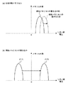
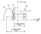
図4乃至図7は従来技術及び実施形態に係る書き込み方法に係る書き込み方法による4値のフラッシュEEPROMのしきい値電圧の確率分布を示す図である。ここで、2ビットのマルチレベルセル(MLC)の書き込みは、それぞれ図4(a)及び図4(b)に示すように、下位ビット(LSB)と上位ビット(MSB)に分けて行われる。これは、LSBの書き込み時のしきい値電圧(Vth)シフトによるしきい値分布の上昇現象はMSBの書き込み時にはキャンセルすることができるからであり、特許文献8においてその詳細が記述されている。ここで、図4に示すように、データ値(1,1)からデータ値(0.1)へのMSBの書き込み時のしきい値電圧(Vth)の変化量ΔVth2は、LSBデータ値(1,0)からデータ値(0,0)へのMSBの書き込み時のしきい値電圧(Vth)の変化量ΔVth1の約2倍となっており、その分、しきい値電圧の上昇現象も大きい。そのため、図6に示すように、データの消去の後に続いて弱い書き込み(ソフトプログラム)を行い、消去後のしきい値分布幅の縮小を図っている。
4 to 7 are diagrams showing probability distributions of threshold voltages of a quaternary flash EEPROM according to the writing method according to the conventional technique and the writing method according to the embodiment. Here, the writing of the 2-bit multi-level cell (MLC) is performed separately for the lower bit (LSB) and the upper bit (MSB) as shown in FIGS. 4 (a) and 4 (b). This is because an increase in threshold distribution due to a threshold voltage (Vth) shift during LSB writing can be canceled during MSB writing, and details thereof are described in
しかしながら、従来技術のソフトプログラムは全セル同時に行い、全ワード線一括でベリファイを行うために、しきい値分布幅の縮小には限界があった。もし(1,1)分布を図7の斜線で示した分布のように縮小できたならば、しきい値効果も大きく削減できることになる。 However, since the soft program of the prior art is performed simultaneously for all the cells and the verify operation is performed for all the word lines, there is a limit to the reduction of the threshold distribution width. If the (1,1) distribution can be reduced as shown by the hatched lines in FIG. 7, the threshold effect can be greatly reduced.
本発明の目的は以上の問題点を解決し、隣接のビット線及びワード線を用いたメモリセルへの書き込み完了時に、それらに囲まれたビットのメモリセルにおけるしきい値分布の上昇現象を最小化できる不揮発性半導体記憶装置とその書き込み方法を提供することにある。 The object of the present invention is to solve the above-described problems, and to minimize the rise in threshold distribution in the memory cells of the bits surrounded by them when writing to the memory cells using adjacent bit lines and word lines is completed. It is an object of the present invention to provide a nonvolatile semiconductor memory device and a writing method thereof.
第1の発明に係る不揮発性半導体記憶装置は、各メモリセルに複数の異なるしきい値を設定することにより多値を記録する不揮発性のメモリセルアレイと、上記メモリセルアレイへの書き込みを制御する制御回路とを備えた不揮発性半導体記憶装置において、
上記制御回路は、上記メモリセルに対してデータを書き込んだとき、隣接のワード線を選択し、上記データの書き込みよりも弱い書き込みを消去レベルで行い、1ページ分のソフトプログラムのベリファイを行うことにより、隣接メモリセルにおいて狭帯化された消去レベル分布を実現できることを特徴とする。
A non-volatile semiconductor memory device according to a first aspect of the present invention is a non-volatile memory cell array that records multiple values by setting a plurality of different threshold values for each memory cell, and a control that controls writing to the memory cell array. In a nonvolatile semiconductor memory device comprising a circuit,
When the data is written to the memory cell, the control circuit selects an adjacent word line, performs a weaker write than the data write at the erase level, and verifies the soft program for one page. Thus, it is possible to realize a narrowed erase level distribution in adjacent memory cells.
上記不揮発性半導体記憶装置において、上記不揮発性半導体記憶装置は、第1と第2のラッチを含むページバッファを備え、
上記制御回路は、処理対象のメモリセルに書き込むべきページデータを上記第2のラッチに格納し、書き込み指示のプログラム発生コマンドに応答して、上記ページデータを上記第2のラッチから上記第1のラッチに転送してコピーし、上記ページデータを当該メモリセルに書き込んだ後、次に書き込むべき隣接のワード線を選択し、上記データの書き込みよりも弱い書き込みを消去レベルで行い、1ページ分のソフトプログラムのベリファイを行うことを特徴とする。
In the nonvolatile semiconductor memory device, the nonvolatile semiconductor memory device includes a page buffer including first and second latches,
The control circuit stores page data to be written into a memory cell to be processed in the second latch, and responds to a program generation command of a write instruction to transfer the page data from the second latch to the first latch. After transferring to the latch and copying and writing the page data into the memory cell, the adjacent word line to be written next is selected, writing weaker than the data writing is performed at the erase level, and one page worth It is characterized by verifying a soft program.
また、上記不揮発性半導体記憶装置において、上記不揮発性半導体記憶装置は、第1と第2のラッチを含むページバッファを備え、
上記制御回路は、処理対象のメモリセルに書き込むべきページデータを上記第2のラッチに格納し、書き込み指示のプログラム発生コマンドに応答して、次に書き込むべき隣接のワード線を選択し、上記データの書き込みよりも弱い書き込みを消去レベルで行い、1ページ分のソフトプログラムのベリファイを行った後、上記ページデータを上記第2のラッチから上記第1のラッチに転送してコピーし、上記ページデータを当該メモリセルに書き込むことを特徴とする。
In the nonvolatile semiconductor memory device, the nonvolatile semiconductor memory device includes a page buffer including first and second latches,
The control circuit stores page data to be written in a memory cell to be processed in the second latch, selects an adjacent word line to be written next in response to a program generation command of a write instruction, and After the soft program is verified for one page, the page data is transferred from the second latch to the first latch and copied, and then the page data is copied. Is written in the memory cell.
第2の発明に係る不揮発性半導体記憶装置の書き込み方法は、各メモリセルに複数の異なるしきい値を設定することにより多値を記録する不揮発性のメモリセルアレイと、上記メモリセルアレイへの書き込みを制御する制御回路とを備えた不揮発性半導体記憶装置の書き込み方法において、
上記制御回路は、上記メモリセルに対してデータを書き込んだとき、隣接のワード線を選択し、上記データの書き込みよりも弱い書き込みを消去レベルで行い、1ページ分のソフトプログラムのベリファイを行うことにより、隣接メモリセルにおいて狭帯化された消去レベル分布を実現できることを特徴とする。
According to a second aspect of the present invention, there is provided a non-volatile semiconductor memory device writing method including: a non-volatile memory cell array that records multiple values by setting a plurality of different threshold values for each memory cell; In a writing method of a nonvolatile semiconductor memory device including a control circuit for controlling,
When the data is written to the memory cell, the control circuit selects an adjacent word line, performs a weaker write than the data write at the erase level, and verifies the soft program for one page. Thus, it is possible to realize a narrowed erase level distribution in adjacent memory cells.
上記不揮発性半導体記憶装置の書き込み方法において、上記不揮発性半導体記憶装置は、第1と第2のラッチを含むページバッファを備え、
上記制御回路は、処理対象のメモリセルに書き込むべきページデータを上記第2のラッチに格納し、書き込み指示のプログラム発生コマンドに応答して、上記ページデータを上記第2のラッチから上記第1のラッチに転送してコピーし、上記ページデータを当該メモリセルに書き込んだ後、次に書き込むべき隣接のワード線を選択し、上記データの書き込みよりも弱い書き込みを消去レベルで行い、1ページ分のソフトプログラムのベリファイを行うことを特徴とする。
In the nonvolatile semiconductor memory device writing method, the nonvolatile semiconductor memory device includes a page buffer including first and second latches,
The control circuit stores page data to be written into a memory cell to be processed in the second latch, and responds to a program generation command of a write instruction to transfer the page data from the second latch to the first latch. After transferring to the latch and copying and writing the page data into the memory cell, the adjacent word line to be written next is selected, writing weaker than the data writing is performed at the erase level, and one page worth It is characterized by verifying a soft program.
また、上記不揮発性半導体記憶装置の書き込み方法において、上記不揮発性半導体記憶装置は、第1と第2のラッチを含むページバッファを備え、
上記制御回路は、処理対象のメモリセルに書き込むべきページデータを上記第2のラッチに格納し、書き込み指示のプログラム発生コマンドに応答して、次に書き込むべき隣接のワード線を選択し、上記データの書き込みよりも弱い書き込みを消去レベルで行い、1ページ分のソフトプログラムのベリファイを行った後、上記ページデータを上記第2のラッチから上記第1のラッチに転送してコピーし、上記ページデータを当該メモリセルに書き込むことを特徴とする。
Further, in the writing method of the nonvolatile semiconductor memory device, the nonvolatile semiconductor memory device includes a page buffer including first and second latches,
The control circuit stores page data to be written in a memory cell to be processed in the second latch, selects an adjacent word line to be written next in response to a program generation command of a write instruction, and After the soft program is verified for one page, the page data is transferred from the second latch to the first latch and copied, and then the page data is copied. Is written in the memory cell.
従って、本発明に係る不揮発性半導体記憶装置とその書き込み方法によれば、上記制御回路は、上記メモリセルに対してデータを書き込んだとき、隣接のワード線を選択し、上記データの書き込みよりも弱い書き込みを消去レベルで行い、1ページ分のソフトプログラムのベリファイを行うことにより、隣接メモリセルにおいて狭帯化された消去レベル分布を実現できる。これにより、例えば、データ値(1,1)からデータ値(0,1)へのしきい値電圧Vthのシフト量を均一化してかつ最小化できるため、書き込みにおいて発生する隣接ビットによるしきい値分布の上昇現象の影響を最小限に抑えることができる。これにより、リードマージンに対する見積もりが容易になり、かつしきい値分布間にウィンドウを確保できる。従って、メモリセルへの書き込み及び読み取りの誤り確率を大幅に軽減できる。 Therefore, according to the nonvolatile semiconductor memory device and the writing method thereof according to the present invention, the control circuit selects an adjacent word line when data is written to the memory cell, so that By performing weak writing at the erase level and verifying the soft program for one page, a narrowed erase level distribution can be realized in adjacent memory cells. As a result, for example, the shift amount of the threshold voltage Vth from the data value (1, 1) to the data value (0, 1) can be made uniform and minimized. The influence of the distribution rising phenomenon can be minimized. This makes it easy to estimate the lead margin and secures a window between the threshold distributions. Therefore, the error probability of writing and reading to the memory cell can be greatly reduced.
以下、本発明に係る実施形態について図面を参照して説明する。なお、以下の各実施形態において、同様の構成要素については同一の符号を付している。 Hereinafter, embodiments according to the present invention will be described with reference to the drawings. In addition, in each following embodiment, the same code | symbol is attached | subjected about the same component.
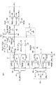
図1は本発明の一実施形態に係るNAND型フラッシュEEPROMの全体構成を示すブロック図である。また、図2は図1のメモリセルアレイ10とその周辺回路の構成を示す回路図である。さらに、図3は図2のページバッファ(2本のビットライン分)の詳細構成を示す回路図である。まず、本実施形態に係るNAND型フラッシュEEPROMの構成について以下に説明する。
FIG. 1 is a block diagram showing the overall configuration of a NAND flash EEPROM according to an embodiment of the present invention. FIG. 2 is a circuit diagram showing the configuration of the
図1において、本実施形態に係るNAND型フラッシュEEPROMは、メモリセルアレイ10と、その動作を制御する制御回路11と、ロウデコーダ12と、高電圧発生回路13と、データ書き換え及び読み出し回路14と、カラムデコーダ15と、コマンドレジスタ17と、アドレスレジスタ18と、動作ロジックコントローラ19と、データ入出力バッファ50と、データ入出力端子51とを備えて構成される。
In FIG. 1, a NAND flash EEPROM according to this embodiment includes a
メモリセルアレイ10は、図2に示すように、例えば16個のスタックト・ゲート構造の電気的書き換え可能な不揮発性メモリセルMC0〜MC15を直列接続してNANDセルユニットNU(NU0,NU1, …)が構成される。各NANDセルユニットNUは、ドレイン側が選択ゲートトランジスタSG1を介してビット線BLに接続され、ソース側が選択ゲートトランジスタSG2を介して共通ソース線CELSRCに接続される。ロウ方向に並ぶメモリセルMCの制御ゲートは共通にワード線WLに接続され、選択ゲートトランジスタSG1,SG2のゲート電極はワード線WLと平行して配設される選択ゲート線SGD,SGSに接続される。1本のワード線WLにより選択されるメモリセルの範囲が書き込み及び読み出しの単位となる1ページである。1ページ又はその整数倍の範囲の複数のNANDセルユニットNUの範囲がデータ消去の単位である1ブロックとなる。書き換え及び読み出し回路14は、ページ単位のデータ書き込み及び読み出しを行うために、ビット線毎に設けられたセンスアンプ回路(SA)及びラッチ回路(DL)を含み、以下、ページバッファという。
As shown in FIG. 2, the
図2のメモリセルアレイ10は、簡略化した構成を有し、複数のビット線でページバッファを共有してもよい。この場合は、データ書き込み又は読み出し動作時にページバッファに選択的に接続されるビット線数が1ページの単位となる。また、図2は、1個の入出力端子52との間でデータの入出力が行われるセルアレイの範囲を示している。メモリセルアレイ10のワード線WL及びビット線BLの選択を行うために、それぞれロウデコーダ12及びカラムデコーダ15が設けられている。制御回路11は、データ書き込み、消去及び読み出しのシーケンス制御を行う。制御回路11により制御される高電圧発生回路13は、データ書き換え、消去、読み出しに用いられる昇圧された高電圧や中間電圧を発生する。
The
入出力バッファ50は、データの入出力及びアドレス信号の入力に用いられる。すなわち、入出力バッファ50及びデータ線52を介して、入出力端子51とページバッファ14の間でデータの転送が行われる。入出力端子52から入力されるアドレス信号は、アドレスレジスタ18に保持され、ロウデコーダ12及びカラムデコーダ15に送られてデコードされる。入出力端子52からは動作制御のコマンドも入力される。入力されたコマンドはデコードされてコマンドレジスタ17に保持され、これにより制御回路11が制御される。チップイネーブル信号CEB、コマンドラッチイネーブルCLE、アドレスラッチイネーブル信号ALE、書き込みイネーブル信号WEB、読み出しイネーブル信号REB等の外部制御信号は動作ロジックコントロール回路19に取り込まれ、動作モードに応じて内部制御信号が発生される。内部制御信号は、入出力バッファ50でのデータラッチ、転送等の制御に用いられ、さらに制御回路11に送られて、動作制御が行われる。
The input /
ページバッファ14は、2個のラッチ回路14a,14bを備え、多値動作の機能とキャッシュの機能を切り換えて実行できるように構成されている。すなわち、1つのメモリセルに1ビットの2値データを記憶する場合に、キャッシュ機能を備え、1つのメモリセルに2ビットの4値データを記憶する場合には、キャッシュ機能とするか、又はアドレスによって制限されるがキャッシュ機能を有効とすることができる。そのような機能を実現するための具体的なページバッファ14A(2本のビットライン分)の詳細構成を図3に示す。
The
図3において、ページバッファ14Aは、2個のインバータ61,62にてなるラッチL1と、2個のインバータ63,64にてなるラッチL2と、ベリファイ用キャパシタ70と、プリチャージ用トランジスタ71と、ベリファイ用トランジスタ72乃至75と、プルアップトランジスタ76,77と、カラムゲートトランジスタ81,82と、転送スイッチトランジスタ83乃至85,88,89と、ビットライン選択トランジスタ86,87と、ラッチイネーブルトランジスタ90と、リセットトランジスタ91とを備えて構成される。
In FIG. 3, the
図3において、2本のビット線BLe,BLoがページバッファ14Aに選択的に接続されるようになっている。この場合、ビット線選択信号BLSE又はBLSOによって、ビットライン選択トランジスタ86又は87を導通させ、ビット線BLe又はビット線BLoの一方を選択的にページバッファ14Aに接続する。なお、一方のビット線が選択されている間、非選択状態である他方のビット線は、固定の接地電位や電源電圧電位にすることによって、隣接ビット線間のノイズを削減することが好ましい。
In FIG. 3, two bit lines BLe and BLo are selectively connected to the
図3のページバッファ14Aは、第1のラッチL1と、第2のラッチL2とを有する。ページバッファ14Aは所定の動作制御によって、主に読み出し、書き込み動作に寄与する。また、第2のラッチL2は、2値動作においては、キャッシュ機能を実現する二次的なラッチ回路であり、キャッシュ機能を使用しない場合には当該ページバッファ14Aの動作に補助的に寄与して多値動作を実現する。
The
ラッチL1は、クロックト・インバータ61,62を逆並列接続して構成されている。メモリセルアレイ10のビット線BLは、転送スイッチトランジスタ85を介してセンスノードN4に接続され、センスノードN4はさらに転送スイッチトランジスタ83を介してラッチL1のデータ保持ノードN1に接続されている。センスノードN4には、プリチャージ用トランジスタ71が設けられている。ノードN1は、転送スイッチトランジスタ74,75を介してノードN1のデータを一時記憶するための一時記憶ノードN3に接続されている。さらに、ノードN4には、ビット線に対して電圧V1をプリチャージするためのプリチャージ用トランジスタ71も接続されている。ノードN4にはレベル保持のためのキャパシタ70が接続されている。キャパシタ70の他端は接地される。
The latch L1 is configured by connecting clocked
第2のラッチL2は、第1のラッチL1と同様に、クロックト・インバータ63,64を逆並列接続して構成されている。ラッチL2の2つのデータノードN5,N6は、カラム選択信号CSLにより制御されるカラムゲートトランジスタ81,82を介して、データ入出力バッファ50に接続されるデータ線52に接続される。ノードN5は、転送スイッチトランジスタ84を介して、ノードN4に接続される。
Similarly to the first latch L1, the second latch L2 is configured by connecting clocked
図3は、メモリセルアレイ10と、ページバッファ14と、データ入出力バッファ50の接続関係を示す。NAND型フラッシュEEPROMの読み出し、書き込みの処理単位は、あるロウアドレスでの同時に選択される1ページ分の容量(例えば512バイト)となっている。8個のデータ入出力端子52があるため、1つのデータ入出力端子52に対しては、512ビットとなっており、図3ではその512ビット分の構成を示している。
FIG. 3 shows a connection relationship among the
データをメモリセルに書き込む場合には、データ信号線52から書き込みデータを第2のラッチL2に取り込む。書き込み動作を開始するには、書き込みデータが第1のラッチL1になければならないので、続いて、ラッチL2に保持したデータをラッチ回路L1に転送する。また、読み出し動作においては、データ入出力端子51にデータを出力するには、読み出したデータがラッチL2になければならないので、ラッチL1で読み出したデータをラッチL2に転送する必要がある。従って、転送スイッチトランジスタ83,84を導通状態にしてラッチL1とラッチL2の間でデータを転送を行うことが可能なように構成されている。このとき、転送先のラッチ回路を非活性状態にしてからデータを転送し、その後転送先のラッチ回路を活性状態に戻してデータを保持することなる。
When data is written to the memory cell, the write data is fetched from the data signal
なお、図1乃至図3において、メモリセルアレイ10へのデータの書き込み、消去の基本動作は例えば非特許文献4−5において開示されており周知技術であり、詳細説明を省略する。
1 to 3, the basic operation of writing and erasing data in the
本実施形態では、フラッシュEEPROMにおいて、書き込みにおいて発生する隣接ビットの影響を最小限に抑える方法を開示しており、選択されているワード線に対して、次に選択されるワード線の消去レベルのしきい値分布幅を縮めることにより、起こりうる影響を抑える。これにより、次に選択されたワード線の書き込みによるしきい値の上昇効果を小さくする。 In the present embodiment, a method for minimizing the influence of adjacent bits generated in writing in a flash EEPROM is disclosed, and the erase level of the next selected word line is set to the selected word line. By reducing the threshold distribution width, possible effects are suppressed. As a result, the effect of raising the threshold by writing the next selected word line is reduced.
消去動作後にできるしきい値電圧分布は、図4又は図6に示すように例えば2V−3Vのしきい値分布幅を有する。このため、消去動作中にそのしきい値電圧を最小にするため、弱い書き込みパルスを与えるが、一度にベリフアイされる数が大きいことでその効果は小さい。また、ワード線毎のベリファイを行う場合には消去自身の全体時間が長くなる。そこで、書き込み動作時に隣接のワード線を選択し、そこで、データの書き込みよりも弱い書き込みを与え、通常のデータ書き込みのように、1ページ分のベリファイを行うことで解決することを特徴としている。 The threshold voltage distribution generated after the erase operation has a threshold distribution width of 2V-3V, for example, as shown in FIG. 4 or FIG. For this reason, a weak write pulse is applied in order to minimize the threshold voltage during the erase operation, but the effect is small because the number of verifying is large at one time. In addition, when verify is performed for each word line, the entire time for erasing itself becomes longer. Therefore, it is characterized in that the problem is solved by selecting an adjacent word line during the write operation, giving a weaker write than the data write, and verifying for one page as in the normal data write.
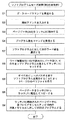
図8は図1の制御回路11により実行される本実施形態に係るソフトプログラムモード処理を示すフローチャートである。 FIG. 8 is a flowchart showing a soft program mode process according to the present embodiment, which is executed by the control circuit 11 of FIG.
図8において、まず、ステップS1において、データロードコマンドを受信し、ステップS2において開始アドレスを入力する。次いで、ステップS3においてページデータ(2kB)をラッチL2に格納し、ステップS4においてプログラム発生コマンドを受信する。そして、ステップS5において、ページデータをラッチL2からラッチL1に転送してコピーし、ステップS6においてラッチL1に格納されたページデータに基づいて、メモリセルアレイ10内の対象メモリセルに対してLSBをプログラムする。次いで、ステップS7においてソフトプログラムに対して、現在処理対象のワード線とは隣接する次のワード線を選択し、ステップS8においてすべてのビットがパスするまでソフトプログラムを実行することにより1ページ分のベリファイを行う。ここで、ソフトプログラムは1ページ分のすべてのメモリセルに対して行われる。
In FIG. 8, first, a data load command is received in step S1, and a start address is input in step S2. Next, page data (2 kB) is stored in the latch L2 in step S3, and a program generation command is received in step S4. In step S5, the page data is transferred from the latch L2 to the latch L1 and copied. In step S6, the LSB is programmed for the target memory cell in the
なお、本実施形態に係るソフトプログラムモード処理における各電圧について以下に示。ここで、弱い書き込みにおける処理は従来技術に係る通常の書き込み処理と同様であるが、プログラム時のワード線WL電圧とベリファイ時のワード線WL電圧、特に、ベリファイ時の電圧が異なる。ここでは、図3のビットラインBLoが選択されている場合の各電圧の一例を次の表に示す。 Each voltage in the soft program mode processing according to the present embodiment is shown below. Here, the processing in weak writing is the same as the normal writing processing according to the prior art, but the word line WL voltage at the time of programming and the word line WL voltage at the time of verification, particularly, the voltage at the time of verification are different. Here, an example of each voltage when the bit line BLo of FIG. 3 is selected is shown in the following table.

以上説明したように、本実施形態によれば、メモリセルアレイ10内のメモリセルに対してデータを書き込んだとき、隣接のワード線を選択し、上記データの書き込みよりも弱い書き込みを行い、1ページ分のベリファイを行うので、図7のしきい値分布101から102への矢印103での推移に示すように、本発明に係る弱い書き込みが行われた消去レベル分布からの書き込みは、大きなしきい値のシフトはないので、選択されているワード線に対して次に選択され書き込みされるワード線のしきい値分布の上昇効果を小さくする(図7の101の斜線で示すしきい値分布参照。)ことができ、書き込みにおいて発生する隣接ビットの影響を最小限に抑えることができる。これにより、リードマージンに対する見積もりが容易になり、かつしきい値分布間にウィンドウを確保できる。従って、メモリセルへの書き込み及び読み取りの誤り確率を大幅に軽減できる。
As described above, according to the present embodiment, when data is written to a memory cell in the
変形例.
図8の実施形態に係るソフトプログラムモード処理のフローチャートでは、選択されたメモリセルのLSBデータの書き込みの後に隣接するワード線WL上の隣接のメモリセルの消去レベル分布のソフトプログラムを行っているが、これは、選択メモリセルに対するLSBデータの書き込み直前に行ってもよい。また、選択メモリセルのMSBデータの書き込み直前に行ってもよい。これらの変形例を以下に示す。
Modified example.
In the flowchart of the soft program mode process according to the embodiment of FIG. 8, the soft program of the erase level distribution of the adjacent memory cell on the adjacent word line WL is performed after the LSB data write of the selected memory cell. This may be performed immediately before the LSB data is written to the selected memory cell. Alternatively, it may be performed immediately before the MSB data of the selected memory cell is written. These modifications are shown below.
図9は第1の変形例に係るソフトプログラムモード処理を示すフローチャートである。図9の処理は、図8の処理に比較して、ステップS7及びS8の処理を、ステップS4とステップS5との間に挿入したことを特徴としている。また、図10は第2の変形例に係るソフトプログラムモード処理を示すフローチャートである。図10の処理は、図9の処理に比較して、ステップS6において、LSBのプログラムに代えてMSBのプログラムを行うことを特徴としている。さらに、図11は第3の変形例に係るソフトプログラムモード処理を示すフローチャートである。図11の処理は、図10の処理に比較して、「ワード線電圧WL=0Vで読み出し、データ値(1,1)のみをソフトプログラム対象としてラッチL1にセットする」ステップS9処理を、ステップS7とステップS8との間に挿入したことを特徴としている。図10の処理では、隣接メモリセルはすでにLSBのデータが書かれているのを無視してソフトプログラムを行うが、1回の書き込みにてデータ値(1,0)へのベリファイはパスするためにほとんど影響はない。図11の処理では、その点を解決するようにステップS9の処理を挿入したものである。
FIG. 9 is a flowchart showing soft program mode processing according to the first modification. The process of FIG. 9 is characterized in that the processes of steps S7 and S8 are inserted between steps S4 and S5, compared to the process of FIG. FIG. 10 is a flowchart showing soft program mode processing according to the second modification. Compared with the process of FIG. 9, the process of FIG. 10 is characterized in that, in step S6, the MSB program is executed instead of the LSB program. Further, FIG. 11 is a flowchart showing soft program mode processing according to the third modification. Compared with the processing of FIG. 10, the processing of FIG. 11 “
以上の実施形態においては、NAND型フラッシュEEPROMについて説明しているが、本発明はこれに限らず、NOR型フラッシュEEPROMなどのフローティングゲートにデータを書き込むことが可能な不揮発性半導体記憶装置に広く適用できる。 Although the NAND flash EEPROM has been described in the above embodiments, the present invention is not limited to this, and is widely applied to nonvolatile semiconductor memory devices capable of writing data to a floating gate such as a NOR flash EEPROM. it can.
以上の実施形態においては、図4のしきい値分布を仮定して、最低の電圧を有するデータをプログラムすることを説明しているが、本発明はこれに限らず、多値のいずれかのデータをプログラムするときに適用できる。 In the above embodiment, it is described that the data having the lowest voltage is programmed assuming the threshold distribution of FIG. 4, but the present invention is not limited to this, and any one of multi-values is described. Applicable when programming data.
以上詳述したように、本発明によれば、上記メモリセルに対してデータを書き込んだとき、隣接のワード線を選択し、上記データの書き込みよりも弱い書き込みを消去レベルで行い、1ページ分のソフトプログラムのベリファイを行うことにより、隣接メモリセルにおいて狭帯化された消去レベル分布を実現できる。これにより、例えば、データ値(1,1)からデータ値(0,1)へのしきい値電圧Vthのシフト量を均一化してかつ最小化できるため、書き込みにおいて発生する隣接ビットによるしきい値分布の上昇現象の影響を最小限に抑えることができる。これにより、リードマージンに対する見積もりが容易になり、かつしきい値分布間にウィンドウを確保できる。従って、メモリセルへの書き込み及び読み取りの誤り確率を大幅に軽減できる。ここで、本発明は特に、NAND型フラッシュEEPROM、又はNOR型フラッシュEEPROMなどのフローティングゲートにデータを書き込むことが可能な不揮発性半導体記憶装置に利用できる。 As described above in detail, according to the present invention, when data is written to the memory cell, an adjacent word line is selected, and writing that is weaker than the data writing is performed at the erase level. By performing the verification of the soft program, it is possible to realize a narrowed erase level distribution in adjacent memory cells. As a result, for example, the shift amount of the threshold voltage Vth from the data value (1, 1) to the data value (0, 1) can be made uniform and minimized. The influence of the distribution rising phenomenon can be minimized. This makes it easy to estimate the lead margin and secures a window between the threshold distributions. Therefore, the error probability of writing and reading to the memory cell can be greatly reduced. Here, the present invention is particularly applicable to a nonvolatile semiconductor memory device capable of writing data to a floating gate such as a NAND flash EEPROM or a NOR flash EEPROM.
10…メモリセルアレイ、
11…制御回路、
12…ロウデコーダ、
13…高電圧発生回路、
14,14A…データ書き換え及び読み出し回路(ページバッファ)、
14a,14b…ラッチ回路、
15…カラムデコーダ、
17…コマンドレジスタ、
18…アドレスレジスタ、
19…動作ロジックコントローラ、
50…データ入出力バッファ、
51…データ入出力端子、
52…データ線、
61乃至64…インバータ、
70…ベリファイ用キャパシタ、
71…プリチャージ用トランジスタ、
72乃至75…ベリファイ用トランジスタ、
76,77…プルアップトランジスタ、
81,82…カラムゲートトランジスタ、
83乃至85,88,89…転送スイッチトランジスタ、
86,87…ビットライン選択トランジスタ、
90…ラッチイネーブルトランジスタ、
91…リセットトランジスタ、
L1,L2…ラッチ。
10: Memory cell array,
11 ... control circuit,
12 ... row decoder,
13. High voltage generation circuit,
14, 14A ... Data rewriting and reading circuit (page buffer),
14a, 14b ... latch circuit,
15 ... column decoder,
17 ... Command register,
18 ... Address register,
19 ... Operation logic controller,
50: Data input / output buffer,
51: Data input / output terminal,
52 ... Data line,
61 to 64: inverter,
70: Verification capacitor,
71 ... Precharge transistor,
72 to 75 ... verifying transistors,
76, 77 ... Pull-up transistor,
81, 82 ... column gate transistors,
83 to 85, 88, 89... Transfer switch transistor,
86, 87 ... bit line selection transistors,
90 ... Latch enable transistor,
91 ... Reset transistor,
L1, L2 ... Latch.
Claims (2)
上記制御回路は、上記メモリセルに対してデータを書き込んだとき、隣接のワード線を選択し、上記データの書き込みよりも弱い書き込みを消去レベルで行い、1ページ分のソフトプログラムのベリファイを行うことにより、隣接メモリセルにおいて狭帯化された消去レベル分布を実現でき、
上記不揮発性半導体記憶装置は、第1と第2のラッチを含むページバッファを備え、
上記制御回路は、処理対象のメモリセルに書き込むべきページデータを上記第2のラッチに格納し、書き込み指示のプログラム発生コマンドに応答して、次に書き込むべき隣接のワード線を選択し、上記データの書き込みよりも弱い書き込みを消去レベルで行い、1ページ分のソフトプログラムのベリファイを行った後、上記ページデータを上記第2のラッチから上記第1のラッチに転送してコピーし、上記ページデータを当該メモリセルに書き込むことを特徴とする不揮発性半導体記憶装置。 In a nonvolatile semiconductor memory device comprising: a nonvolatile memory cell array that records multiple values by setting a plurality of different threshold values for each memory cell; and a control circuit that controls writing to the memory cell array.
The control circuit selects an adjacent word line when data is written to the memory cell, performs weaker write than the data write at the erase level, and performs verification of the soft program for one page. Can realize an erase level distribution narrowed in adjacent memory cells ,
The nonvolatile semiconductor memory device includes a page buffer including first and second latches,
The control circuit stores page data to be written in a memory cell to be processed in the second latch, selects an adjacent word line to be written next in response to a program generation command of a write instruction, and After the soft program is verified for one page, the page data is transferred from the second latch to the first latch and copied, and then the page data is copied. Is written in the memory cell .
上記制御回路は、上記メモリセルに対してデータを書き込んだとき、隣接のワード線を選択し、上記データの書き込みよりも弱い書き込みを消去レベルで行い、1ページ分のソフトプログラムのベリファイを行うことにより、隣接メモリセルにおいて狭帯化された消去レベル分布を実現でき、
上記不揮発性半導体記憶装置は、第1と第2のラッチを含むページバッファを備え、
上記制御回路は、処理対象のメモリセルに書き込むべきページデータを上記第2のラッチに格納し、書き込み指示のプログラム発生コマンドに応答して、次に書き込むべき隣接のワード線を選択し、上記データの書き込みよりも弱い書き込みを消去レベルで行い、1ページ分のソフトプログラムのベリファイを行った後、上記ページデータを上記第2のラッチから上記第1のラッチに転送してコピーし、上記ページデータを当該メモリセルに書き込むことを特徴とする不揮発性半導体記憶装置の書き込み方法。 A method for writing to a nonvolatile semiconductor memory device, comprising: a nonvolatile memory cell array that records multiple values by setting a plurality of different threshold values for each memory cell; and a control circuit that controls writing to the memory cell array In
When the data is written to the memory cell, the control circuit selects an adjacent word line, performs a weaker write than the data write at the erase level, and verifies the soft program for one page. Can realize an erase level distribution narrowed in adjacent memory cells ,
The nonvolatile semiconductor memory device includes a page buffer including first and second latches,
The control circuit stores page data to be written in a memory cell to be processed in the second latch, selects an adjacent word line to be written next in response to a program generation command of a write instruction, and After the soft program is verified for one page, the page data is transferred from the second latch to the first latch and copied, and then the page data is copied. Is written in the memory cell . A writing method of a nonvolatile semiconductor memory device,
Priority Applications (3)
| Application Number | Priority Date | Filing Date | Title |
|---|---|---|---|
| JP2007328525A JP4510072B2 (en) | 2007-12-20 | 2007-12-20 | Nonvolatile semiconductor memory device and writing method thereof |
| PCT/JP2008/072507 WO2009081745A1 (en) | 2007-12-20 | 2008-12-11 | Nonvolatile semiconductor storage device |
| US12/808,265 US8738836B2 (en) | 2007-12-20 | 2008-12-11 | Non-volatile semiconductor memory device and write-in method thereof |
Applications Claiming Priority (1)
| Application Number | Priority Date | Filing Date | Title |
|---|---|---|---|
| JP2007328525A JP4510072B2 (en) | 2007-12-20 | 2007-12-20 | Nonvolatile semiconductor memory device and writing method thereof |
Publications (3)
| Publication Number | Publication Date |
|---|---|
| JP2009151865A JP2009151865A (en) | 2009-07-09 |
| JP2009151865A5 JP2009151865A5 (en) | 2010-04-22 |
| JP4510072B2 true JP4510072B2 (en) | 2010-07-21 |
Family
ID=40801052
Family Applications (1)
| Application Number | Title | Priority Date | Filing Date |
|---|---|---|---|
| JP2007328525A Active JP4510072B2 (en) | 2007-12-20 | 2007-12-20 | Nonvolatile semiconductor memory device and writing method thereof |
Country Status (3)
| Country | Link |
|---|---|
| US (1) | US8738836B2 (en) |
| JP (1) | JP4510072B2 (en) |
| WO (1) | WO2009081745A1 (en) |
Families Citing this family (14)
| Publication number | Priority date | Publication date | Assignee | Title |
|---|---|---|---|---|
| JP5330421B2 (en) * | 2011-02-01 | 2013-10-30 | 株式会社東芝 | Nonvolatile semiconductor memory device |
| KR101184803B1 (en) * | 2011-06-09 | 2012-09-20 | 에스케이하이닉스 주식회사 | Semiconductor device and program method thereof |
| KR20130008300A (en) * | 2011-07-12 | 2013-01-22 | 삼성전자주식회사 | Flash memory device conducting erase operation by using over program and operating method thereof |
| US9076547B2 (en) | 2012-04-05 | 2015-07-07 | Micron Technology, Inc. | Level compensation in multilevel memory |
| US9030870B2 (en) * | 2011-08-26 | 2015-05-12 | Micron Technology, Inc. | Threshold voltage compensation in a multilevel memory |
| TWI534810B (en) | 2011-12-09 | 2016-05-21 | Toshiba Kk | Nonvolatile semiconductor memory device |
| JP5706350B2 (en) * | 2012-02-01 | 2015-04-22 | 株式会社東芝 | Nonvolatile semiconductor memory device |
| JP5819338B2 (en) * | 2013-03-21 | 2015-11-24 | 株式会社東芝 | Semiconductor memory device |
| JP2015053098A (en) | 2013-09-09 | 2015-03-19 | 株式会社東芝 | Nonvolatile semiconductor storage device |
| US20150155039A1 (en) | 2013-12-02 | 2015-06-04 | Silicon Storage Technology, Inc. | Three-Dimensional Flash NOR Memory System With Configurable Pins |
| JP2016054017A (en) * | 2014-09-04 | 2016-04-14 | 株式会社東芝 | Semiconductor memory device |
| KR102246843B1 (en) | 2015-01-15 | 2021-05-03 | 에스케이하이닉스 주식회사 | Data storage device and operating method thereof |
| JP6154879B2 (en) * | 2015-11-18 | 2017-06-28 | ウィンボンド エレクトロニクス コーポレーション | NAND flash memory and programming method thereof |
| US11562791B1 (en) * | 2021-08-09 | 2023-01-24 | Micron Technology, Inc. | Memory devices with four data line bias levels |
Citations (2)
| Publication number | Priority date | Publication date | Assignee | Title |
|---|---|---|---|---|
| JP2006139864A (en) * | 2004-11-12 | 2006-06-01 | Toshiba Corp | Semiconductor memory |
| JP2007305204A (en) * | 2006-05-10 | 2007-11-22 | Toshiba Corp | Nonvolatile semiconductor memory device |
Family Cites Families (9)
| Publication number | Priority date | Publication date | Assignee | Title |
|---|---|---|---|---|
| KR950000273B1 (en) | 1992-02-21 | 1995-01-12 | 삼성전자 주식회사 | Non-volatile semiconductor memory device and optimal write method |
| JP2000285692A (en) | 1999-04-01 | 2000-10-13 | Sony Corp | Non-volatile semiconductor memory, data write-in method, and data read-out method |
| JP2001028575A (en) | 1999-07-13 | 2001-01-30 | Victor Co Of Japan Ltd | Digital broadcast receiver |
| JP3983969B2 (en) | 2000-03-08 | 2007-09-26 | 株式会社東芝 | Nonvolatile semiconductor memory device |
| JP2003346485A (en) | 2002-05-23 | 2003-12-05 | Fujitsu Ltd | Nonvolatile semiconductor storage device and write method of nonvolatile semiconductor storage device |
| JP3913704B2 (en) | 2003-04-22 | 2007-05-09 | 株式会社東芝 | Nonvolatile semiconductor memory device and electronic device using the same |
| JP4521243B2 (en) | 2004-09-30 | 2010-08-11 | 株式会社東芝 | Nonvolatile semiconductor memory device and data erasing method thereof |
| JP4157562B2 (en) | 2006-01-31 | 2008-10-01 | 株式会社東芝 | Semiconductor integrated circuit device |
| JP2008084471A (en) | 2006-09-28 | 2008-04-10 | Toshiba Corp | Semiconductor memory device |
-
2007
- 2007-12-20 JP JP2007328525A patent/JP4510072B2/en active Active
-
2008
- 2008-12-11 US US12/808,265 patent/US8738836B2/en active Active
- 2008-12-11 WO PCT/JP2008/072507 patent/WO2009081745A1/en active Application Filing
Patent Citations (2)
| Publication number | Priority date | Publication date | Assignee | Title |
|---|---|---|---|---|
| JP2006139864A (en) * | 2004-11-12 | 2006-06-01 | Toshiba Corp | Semiconductor memory |
| JP2007305204A (en) * | 2006-05-10 | 2007-11-22 | Toshiba Corp | Nonvolatile semiconductor memory device |
Also Published As
| Publication number | Publication date |
|---|---|
| US20100299475A1 (en) | 2010-11-25 |
| JP2009151865A (en) | 2009-07-09 |
| US8738836B2 (en) | 2014-05-27 |
| WO2009081745A1 (en) | 2009-07-02 |
Similar Documents
| Publication | Publication Date | Title |
|---|---|---|
| JP4510072B2 (en) | Nonvolatile semiconductor memory device and writing method thereof | |
| TWI650758B (en) | Semiconductor memory device and control method thereof | |
| JP5292052B2 (en) | Nonvolatile semiconductor memory device and writing method thereof | |
| JP4902002B1 (en) | Nonvolatile semiconductor memory device | |
| JP5259481B2 (en) | Nonvolatile semiconductor memory device | |
| JP5150245B2 (en) | Semiconductor memory device | |
| US20080144370A1 (en) | Method of programming multi-level cells and non-volatile memory device including the same | |
| JP2013143155A (en) | Nonvolatile semiconductor memory device and write-in method thereof | |
| US8605512B2 (en) | Nonvolatile semiconductor memory device and method of operating a nonvolatile memory device | |
| JP2005032431A (en) | Flash memory device having multi-level cell and its reading method and programming method | |
| US20150302920A1 (en) | Semiconductor memory device | |
| JP4746658B2 (en) | Semiconductor memory system | |
| JP2008084471A (en) | Semiconductor memory device | |
| JP2009070501A (en) | Read/write control method of nonvolatile semiconductor memory | |
| TWI426518B (en) | Non-volatile semiconductor memory device and method of reading the same | |
| JP2011018397A (en) | Nand flash memory | |
| JP2011150749A (en) | Nonvolatile semiconductor memory device | |
| JP2010134992A (en) | Nonvolatile semiconductor memory unit and method for writing into the same | |
| JP6154879B2 (en) | NAND flash memory and programming method thereof | |
| JP5784788B2 (en) | Nonvolatile semiconductor memory device and writing method thereof | |
| JP2009048750A (en) | Nonvolatile semiconductor memory device | |
| JP5242603B2 (en) | Semiconductor memory device | |
| JP5467938B2 (en) | Semiconductor memory | |
| US8238156B2 (en) | Nonvolatile semiconductor memory device and method of operating the same | |
| US8456920B2 (en) | Semiconductor memory device capable of executing high-speed page copy |
Legal Events
| Date | Code | Title | Description |
|---|---|---|---|
| A711 | Notification of change in applicant |
Free format text: JAPANESE INTERMEDIATE CODE: A711 Effective date: 20090929 |
|
| A521 | Request for written amendment filed |
Free format text: JAPANESE INTERMEDIATE CODE: A821 Effective date: 20090929 |
|
| A521 | Request for written amendment filed |
Free format text: JAPANESE INTERMEDIATE CODE: A523 Effective date: 20100310 |
|
| A621 | Written request for application examination |
Free format text: JAPANESE INTERMEDIATE CODE: A621 Effective date: 20100310 |
|
| A871 | Explanation of circumstances concerning accelerated examination |
Free format text: JAPANESE INTERMEDIATE CODE: A871 Effective date: 20100310 |
|
| A975 | Report on accelerated examination |
Free format text: JAPANESE INTERMEDIATE CODE: A971005 Effective date: 20100326 |
|
| TRDD | Decision of grant or rejection written | ||
| A01 | Written decision to grant a patent or to grant a registration (utility model) |
Free format text: JAPANESE INTERMEDIATE CODE: A01 Effective date: 20100406 |
|
| A01 | Written decision to grant a patent or to grant a registration (utility model) |
Free format text: JAPANESE INTERMEDIATE CODE: A01 |
|
| A61 | First payment of annual fees (during grant procedure) |
Free format text: JAPANESE INTERMEDIATE CODE: A61 Effective date: 20100428 |
|
| FPAY | Renewal fee payment (event date is renewal date of database) |
Free format text: PAYMENT UNTIL: 20130514 Year of fee payment: 3 |
|
| R150 | Certificate of patent or registration of utility model |
Ref document number: 4510072 Country of ref document: JP Free format text: JAPANESE INTERMEDIATE CODE: R150 Free format text: JAPANESE INTERMEDIATE CODE: R150 |
|
| FPAY | Renewal fee payment (event date is renewal date of database) |
Free format text: PAYMENT UNTIL: 20130514 Year of fee payment: 3 |
|
| S533 | Written request for registration of change of name |
Free format text: JAPANESE INTERMEDIATE CODE: R313533 |
|
| FPAY | Renewal fee payment (event date is renewal date of database) |
Free format text: PAYMENT UNTIL: 20130514 Year of fee payment: 3 |
|
| R350 | Written notification of registration of transfer |
Free format text: JAPANESE INTERMEDIATE CODE: R350 |
|
| FPAY | Renewal fee payment (event date is renewal date of database) |
Free format text: PAYMENT UNTIL: 20140514 Year of fee payment: 4 |
|
| R250 | Receipt of annual fees |
Free format text: JAPANESE INTERMEDIATE CODE: R250 |
|
| R250 | Receipt of annual fees |
Free format text: JAPANESE INTERMEDIATE CODE: R250 |
|
| R250 | Receipt of annual fees |
Free format text: JAPANESE INTERMEDIATE CODE: R250 |
|
| R250 | Receipt of annual fees |
Free format text: JAPANESE INTERMEDIATE CODE: R250 |
|
| R250 | Receipt of annual fees |
Free format text: JAPANESE INTERMEDIATE CODE: R250 |
|
| R250 | Receipt of annual fees |
Free format text: JAPANESE INTERMEDIATE CODE: R250 |
|
| R250 | Receipt of annual fees |
Free format text: JAPANESE INTERMEDIATE CODE: R250 |
|
| S111 | Request for change of ownership or part of ownership |
Free format text: JAPANESE INTERMEDIATE CODE: R313113 |
|
| R350 | Written notification of registration of transfer |
Free format text: JAPANESE INTERMEDIATE CODE: R350 |
|
| R250 | Receipt of annual fees |
Free format text: JAPANESE INTERMEDIATE CODE: R250 |
|
| R250 | Receipt of annual fees |
Free format text: JAPANESE INTERMEDIATE CODE: R250 |
|
| R250 | Receipt of annual fees |
Free format text: JAPANESE INTERMEDIATE CODE: R250 |
|
| R250 | Receipt of annual fees |
Free format text: JAPANESE INTERMEDIATE CODE: R250 |