CN103120828A - Safety connector assembly - Google Patents
Safety connector assembly Download PDFInfo
- Publication number
- CN103120828A CN103120828A CN2013100518891A CN201310051889A CN103120828A CN 103120828 A CN103120828 A CN 103120828A CN 2013100518891 A CN2013100518891 A CN 2013100518891A CN 201310051889 A CN201310051889 A CN 201310051889A CN 103120828 A CN103120828 A CN 103120828A
- Authority
- CN
- China
- Prior art keywords
- adapter
- electrical connector
- shell
- connector assembly
- attachment portion
- Prior art date
- Legal status (The legal status is an assumption and is not a legal conclusion. Google has not performed a legal analysis and makes no representation as to the accuracy of the status listed.)
- Pending
Links
- 230000006835 compression Effects 0.000 claims abstract description 33
- 238000007906 compression Methods 0.000 claims abstract description 33
- 238000002560 therapeutic procedure Methods 0.000 claims abstract description 28
- 238000007789 sealing Methods 0.000 claims description 88
- 230000008878 coupling Effects 0.000 claims description 86
- 238000010168 coupling process Methods 0.000 claims description 86
- 238000005859 coupling reaction Methods 0.000 claims description 86
- 206010070995 Vascular compression Diseases 0.000 claims description 6
- 238000007493 shaping process Methods 0.000 claims description 2
- 239000012530 fluid Substances 0.000 abstract description 42
- 206010051055 Deep vein thrombosis Diseases 0.000 abstract description 3
- 206010047249 Venous thrombosis Diseases 0.000 abstract description 3
- 230000013011 mating Effects 0.000 abstract 1
- 230000015572 biosynthetic process Effects 0.000 description 7
- 239000000463 material Substances 0.000 description 7
- 238000012856 packing Methods 0.000 description 6
- 238000009738 saturating Methods 0.000 description 4
- 238000001990 intravenous administration Methods 0.000 description 3
- 239000002904 solvent Substances 0.000 description 3
- 238000003466 welding Methods 0.000 description 3
- 239000008280 blood Substances 0.000 description 2
- 210000004369 blood Anatomy 0.000 description 2
- 238000007599 discharging Methods 0.000 description 2
- 238000004519 manufacturing process Methods 0.000 description 2
- 238000000034 method Methods 0.000 description 2
- 208000007536 Thrombosis Diseases 0.000 description 1
- 230000017531 blood circulation Effects 0.000 description 1
- 235000019994 cava Nutrition 0.000 description 1
- 238000004891 communication Methods 0.000 description 1
- 238000010276 construction Methods 0.000 description 1
- 238000000354 decomposition reaction Methods 0.000 description 1
- 238000010586 diagram Methods 0.000 description 1
- 230000000694 effects Effects 0.000 description 1
- 238000005516 engineering process Methods 0.000 description 1
- 230000002349 favourable effect Effects 0.000 description 1
- 238000003780 insertion Methods 0.000 description 1
- 230000037431 insertion Effects 0.000 description 1
- 238000006386 neutralization reaction Methods 0.000 description 1
- 235000016709 nutrition Nutrition 0.000 description 1
- 230000035764 nutrition Effects 0.000 description 1
- 230000002093 peripheral effect Effects 0.000 description 1
- 238000003825 pressing Methods 0.000 description 1
- 238000000926 separation method Methods 0.000 description 1
- 229910052710 silicon Inorganic materials 0.000 description 1
- 239000010703 silicon Substances 0.000 description 1
- 239000013589 supplement Substances 0.000 description 1
- 150000003673 urethanes Chemical class 0.000 description 1
- 230000002792 vascular Effects 0.000 description 1
Images


Classifications
-
- A—HUMAN NECESSITIES
- A61—MEDICAL OR VETERINARY SCIENCE; HYGIENE
- A61B—DIAGNOSIS; SURGERY; IDENTIFICATION
- A61B17/00—Surgical instruments, devices or methods, e.g. tourniquets
- A61B17/12—Surgical instruments, devices or methods, e.g. tourniquets for ligaturing or otherwise compressing tubular parts of the body, e.g. blood vessels, umbilical cord
- A61B17/132—Tourniquets
- A61B17/135—Tourniquets inflatable
-
- A—HUMAN NECESSITIES
- A61—MEDICAL OR VETERINARY SCIENCE; HYGIENE
- A61H—PHYSICAL THERAPY APPARATUS, e.g. DEVICES FOR LOCATING OR STIMULATING REFLEX POINTS IN THE BODY; ARTIFICIAL RESPIRATION; MASSAGE; BATHING DEVICES FOR SPECIAL THERAPEUTIC OR HYGIENIC PURPOSES OR SPECIFIC PARTS OF THE BODY
- A61H9/00—Pneumatic or hydraulic massage
- A61H9/005—Pneumatic massage
- A61H9/0078—Pneumatic massage with intermittent or alternately inflated bladders or cuffs
-
- A—HUMAN NECESSITIES
- A61—MEDICAL OR VETERINARY SCIENCE; HYGIENE
- A61M—DEVICES FOR INTRODUCING MEDIA INTO, OR ONTO, THE BODY; DEVICES FOR TRANSDUCING BODY MEDIA OR FOR TAKING MEDIA FROM THE BODY; DEVICES FOR PRODUCING OR ENDING SLEEP OR STUPOR
- A61M39/00—Tubes, tube connectors, tube couplings, valves, access sites or the like, specially adapted for medical use
- A61M39/10—Tube connectors; Tube couplings
- A61M39/1011—Locking means for securing connection; Additional tamper safeties
-
- F—MECHANICAL ENGINEERING; LIGHTING; HEATING; WEAPONS; BLASTING
- F16—ENGINEERING ELEMENTS AND UNITS; GENERAL MEASURES FOR PRODUCING AND MAINTAINING EFFECTIVE FUNCTIONING OF MACHINES OR INSTALLATIONS; THERMAL INSULATION IN GENERAL
- F16B—DEVICES FOR FASTENING OR SECURING CONSTRUCTIONAL ELEMENTS OR MACHINE PARTS TOGETHER, e.g. NAILS, BOLTS, CIRCLIPS, CLAMPS, CLIPS OR WEDGES; JOINTS OR JOINTING
- F16B7/00—Connections of rods or tubes, e.g. of non-circular section, mutually, including resilient connections
- F16B7/04—Clamping or clipping connections
- F16B7/0406—Clamping or clipping connections for rods or tubes being coaxial
- F16B7/0413—Clamping or clipping connections for rods or tubes being coaxial for tubes using the innerside thereof
-
- F—MECHANICAL ENGINEERING; LIGHTING; HEATING; WEAPONS; BLASTING
- F16—ENGINEERING ELEMENTS AND UNITS; GENERAL MEASURES FOR PRODUCING AND MAINTAINING EFFECTIVE FUNCTIONING OF MACHINES OR INSTALLATIONS; THERMAL INSULATION IN GENERAL
- F16B—DEVICES FOR FASTENING OR SECURING CONSTRUCTIONAL ELEMENTS OR MACHINE PARTS TOGETHER, e.g. NAILS, BOLTS, CIRCLIPS, CLAMPS, CLIPS OR WEDGES; JOINTS OR JOINTING
- F16B7/00—Connections of rods or tubes, e.g. of non-circular section, mutually, including resilient connections
- F16B7/04—Clamping or clipping connections
- F16B7/0406—Clamping or clipping connections for rods or tubes being coaxial
- F16B7/0426—Clamping or clipping connections for rods or tubes being coaxial for rods or for tubes without using the innerside thereof
-
- F—MECHANICAL ENGINEERING; LIGHTING; HEATING; WEAPONS; BLASTING
- F16—ENGINEERING ELEMENTS AND UNITS; GENERAL MEASURES FOR PRODUCING AND MAINTAINING EFFECTIVE FUNCTIONING OF MACHINES OR INSTALLATIONS; THERMAL INSULATION IN GENERAL
- F16L—PIPES; JOINTS OR FITTINGS FOR PIPES; SUPPORTS FOR PIPES, CABLES OR PROTECTIVE TUBING; MEANS FOR THERMAL INSULATION IN GENERAL
- F16L25/00—Constructive types of pipe joints not provided for in groups F16L13/00 - F16L23/00 ; Details of pipe joints not otherwise provided for, e.g. electrically conducting or insulating means
-
- A—HUMAN NECESSITIES
- A61—MEDICAL OR VETERINARY SCIENCE; HYGIENE
- A61H—PHYSICAL THERAPY APPARATUS, e.g. DEVICES FOR LOCATING OR STIMULATING REFLEX POINTS IN THE BODY; ARTIFICIAL RESPIRATION; MASSAGE; BATHING DEVICES FOR SPECIAL THERAPEUTIC OR HYGIENIC PURPOSES OR SPECIFIC PARTS OF THE BODY
- A61H2205/00—Devices for specific parts of the body
- A61H2205/12—Feet
-
- A—HUMAN NECESSITIES
- A61—MEDICAL OR VETERINARY SCIENCE; HYGIENE
- A61M—DEVICES FOR INTRODUCING MEDIA INTO, OR ONTO, THE BODY; DEVICES FOR TRANSDUCING BODY MEDIA OR FOR TAKING MEDIA FROM THE BODY; DEVICES FOR PRODUCING OR ENDING SLEEP OR STUPOR
- A61M39/00—Tubes, tube connectors, tube couplings, valves, access sites or the like, specially adapted for medical use
- A61M39/10—Tube connectors; Tube couplings
- A61M2039/1027—Quick-acting type connectors
-
- A—HUMAN NECESSITIES
- A61—MEDICAL OR VETERINARY SCIENCE; HYGIENE
- A61M—DEVICES FOR INTRODUCING MEDIA INTO, OR ONTO, THE BODY; DEVICES FOR TRANSDUCING BODY MEDIA OR FOR TAKING MEDIA FROM THE BODY; DEVICES FOR PRODUCING OR ENDING SLEEP OR STUPOR
- A61M39/00—Tubes, tube connectors, tube couplings, valves, access sites or the like, specially adapted for medical use
- A61M39/10—Tube connectors; Tube couplings
- A61M2039/1094—Tube connectors; Tube couplings at least partly incompatible with standard connectors, e.g. to prevent fatal mistakes in connection
-
- A—HUMAN NECESSITIES
- A61—MEDICAL OR VETERINARY SCIENCE; HYGIENE
- A61M—DEVICES FOR INTRODUCING MEDIA INTO, OR ONTO, THE BODY; DEVICES FOR TRANSDUCING BODY MEDIA OR FOR TAKING MEDIA FROM THE BODY; DEVICES FOR PRODUCING OR ENDING SLEEP OR STUPOR
- A61M2205/00—General characteristics of the apparatus
- A61M2205/60—General characteristics of the apparatus with identification means
- A61M2205/6045—General characteristics of the apparatus with identification means having complementary physical shapes for indexing or registration purposes
-
- F—MECHANICAL ENGINEERING; LIGHTING; HEATING; WEAPONS; BLASTING
- F16—ENGINEERING ELEMENTS AND UNITS; GENERAL MEASURES FOR PRODUCING AND MAINTAINING EFFECTIVE FUNCTIONING OF MACHINES OR INSTALLATIONS; THERMAL INSULATION IN GENERAL
- F16L—PIPES; JOINTS OR FITTINGS FOR PIPES; SUPPORTS FOR PIPES, CABLES OR PROTECTIVE TUBING; MEANS FOR THERMAL INSULATION IN GENERAL
- F16L2201/00—Special arrangements for pipe couplings
- F16L2201/20—Safety or protective couplings
-
- Y—GENERAL TAGGING OF NEW TECHNOLOGICAL DEVELOPMENTS; GENERAL TAGGING OF CROSS-SECTIONAL TECHNOLOGIES SPANNING OVER SEVERAL SECTIONS OF THE IPC; TECHNICAL SUBJECTS COVERED BY FORMER USPC CROSS-REFERENCE ART COLLECTIONS [XRACs] AND DIGESTS
- Y10—TECHNICAL SUBJECTS COVERED BY FORMER USPC
- Y10T—TECHNICAL SUBJECTS COVERED BY FORMER US CLASSIFICATION
- Y10T137/00—Fluid handling
- Y10T137/9029—With coupling
-
- Y—GENERAL TAGGING OF NEW TECHNOLOGICAL DEVELOPMENTS; GENERAL TAGGING OF CROSS-SECTIONAL TECHNOLOGIES SPANNING OVER SEVERAL SECTIONS OF THE IPC; TECHNICAL SUBJECTS COVERED BY FORMER USPC CROSS-REFERENCE ART COLLECTIONS [XRACs] AND DIGESTS
- Y10—TECHNICAL SUBJECTS COVERED BY FORMER USPC
- Y10T—TECHNICAL SUBJECTS COVERED BY FORMER US CLASSIFICATION
- Y10T403/00—Joints and connections
- Y10T403/30—Laterally related members connected by latch means, e.g., scaffold connectors
-
- Y—GENERAL TAGGING OF NEW TECHNOLOGICAL DEVELOPMENTS; GENERAL TAGGING OF CROSS-SECTIONAL TECHNOLOGIES SPANNING OVER SEVERAL SECTIONS OF THE IPC; TECHNICAL SUBJECTS COVERED BY FORMER USPC CROSS-REFERENCE ART COLLECTIONS [XRACs] AND DIGESTS
- Y10—TECHNICAL SUBJECTS COVERED BY FORMER USPC
- Y10T—TECHNICAL SUBJECTS COVERED BY FORMER US CLASSIFICATION
- Y10T403/00—Joints and connections
- Y10T403/70—Interfitted members
Abstract
A connector assembly includes first and second mating connectors that can be joined to make a fluid connection. The connectors are constructed to discriminate improper connectors so that no fluid tight connection can be formed with improper connectors. The connector assembly can be used with a system for compression therapy to prevent deep vein thrombosis.
Description
The application be name to be called " safety connector assembly ", international filing date be that JIUYUE in 2007 21 days, international application no are to be the dividing an application of the application for a patent for invention of 200780001149.X PCT/US2007/079214, national applications number, once submitting to name to be called " safety connector assembly ", application number on August 10th, 2011 for this application for a patent for invention is 201110235700.5 divide an application.
Technical field
The disclosure relates to for medical applications, is used in particular for the breaking piece of compression therapy device.The disclosure also relates to the discriminating safety connector assembly, relates in particular to for fluid ground to connect the discriminating safety connector assembly that can form without at least two tube chambers in leak fluid loop.
Background technology
In medical environment, many equipment have pipeline, this pipeline be suitable for manually connecting in case provide between equipment or equipment and comprise the enteral delivery pump and the patient of intravenous feed-line between fluid connect.These equipment include one or more adapters that user or medical practitioner may by mistake link together.This can cause the smooth connection of incompatible equipment or fluid or nutrition supplement to unsuitable intravenous line or equipment, for example is used for the inflatable air bag of Treatment of Deep Venous Thrombosis.Smooth connection meeting patient harm or the damage equipment of incompatible equipment.
When armarium being connected to fluid for seasonable, must form inclusion seal between compatible equipment and/or fluid source.Therefore, connect the abundant sealing that must be designed to provide between sealing surfaces when equipment and/or supply compatibility.Exemplary apparatus has sun and female connector, and when forcing together, described adapter forms not fluid-tight thoroughly.Adapter have different size and shape and typically have O shape ring or packing ring to help to produce fluid-tight thoroughly.
The example that is connected to the armarium of fluid supply comprises compression therapy device, the situation that it is wound to prevent PE and forms blood clot around limbs, for example deep venous thrombosis.These equipment typically comprise at least one air bag, and described air bag size is determined to be and is shaped as for being employed around limbs.Air bag is inflated and shrinks with the artificially stimulates the blood flow that spreads all over appendage that is usually for example produced by walking.The example that is configured to such equipment of arranging around foot shows in the open No.2005/0187499 of the U.S..Typically, these compression devices are connected to the pipe group, and this pipe group provides the fluid from the pressure source to the compression device to be communicated with.Utilize flowing of the fluid of controller adjusting from the pressure source to the compression device.
Compression device, pipe group are connected with controller and are comprised for connecting compression device from pressure source and being connected with pressure source the adapter of disconnection.Wish to avoid the armarium except compression device, for example the intravenous needle incorrect link is to pressure source.
Summary of the invention
In one aspect, a kind of be used to preventing that the connector assembly that is connected with seal for pipe joints nonpermissive, that internal diameter is basically identical, that have end face from comprising the first adapter with base plate and coupling part.Coupling part is outwards outstanding and comprise sealing surfaces and non-tight surface from base plate.The non-tight surface is oriented to the free end than more close the first adapter of sealing surfaces.The non-tight surface size is determined to be and is shaped as and keeps non-permission pipeline to leave sealing surfaces and prevent and its formation sealing.Connector assembly comprises substantially locates to be used for the passing away with the fluid expulsion connector assembly near base plate.
On the other hand, a kind ofly comprise shell for controlling fluid from the compression therapy device controller that source of pressurised fluid is fed to compression therapy device, the fluid port in shell and be used for the connector assembly of fluid port.Connector assembly has adapter, and this adapter has base plate and coupling part.Coupling part comprises sealing surfaces and non-tight surface.The non-tight surface is oriented to the free end than the more close adapter of sealing surfaces.The non-tight surface size is determined to be and is shaped as and keeps non-permission pipeline leave sealing surfaces and prevent and its sealing.Connector assembly comprises substantially locates to be used for the passing away with the fluid expulsion connector assembly near base plate.
Aspect another, a kind of system be used to vascular compression is provided comprises controller, pipe group and compression therapy device.Controller comprises the first connector assembly with first adapter, and the first adapter has base plate and coupling part.Coupling part is outwards outstanding from base plate.Coupling part comprises sealing surfaces and non-tight surface.The non-tight surface is oriented to the free end than more close the first adapter of sealing surfaces.The non-tight surface size is determined to be and is shaped as and keeps non-permission pipeline to leave sealing surfaces and prevent and its formation sealing.The first connector assembly comprises substantially locates to be used for the passing away with fluid expulsion the first connector assembly near base plate.Compression therapy device comprises the second adapter with potted component.The pipe group comprises pipe and at the 3rd adapter of an end of this pipe, the 3rd adapter has potted component, and when connecting with the 3rd adapter when first, the sealing element is suitable for non-tight surface and the sealing surfaces of the first adapter of Engagement Control device.The pipe group comprises the second connector assembly with the 4th adapter, and the 4th adapter has base plate and coupling part, and coupling part comprises that at least one sealing surfaces and at least one non-tight are surperficial.The non-tight surface is oriented to the free end than more close the 4th adapter of sealing surfaces.The non-tight surface size is determined to be and is shaped as and keeps non-permission pipeline to leave sealing surfaces and prevent and its formation sealing.The second connector assembly comprises substantially locates to be used for the passing away with fluid expulsion the second connector assembly near the base plate of shell.When connecting with the 4th adapter when second, the non-tight surface of the 4th adapter is suitable for engaging the potted component of the second adapter.
Therefore, according to the present invention, provide a kind of electrical connector, having comprised: the first adapter, it has shell, attachment portion and coupling part, and this coupling part comprises key; And second adapter, it has shell and attachment portion, and the shell of this second adapter has the coupling chamber that is formed at wherein, and when the first adapter and the second adapter mated with sealing relationship, this coupling chamber was used for catching the key of the first adapter.
Alternatively, this coupling chamber is opening laterally towards the outside of electrical connector, and this first adapter comprises button part, and push button partly make the first adapter distortion and laterally mobile this key leave this coupling chamber.
Alternatively, when being trapped in this coupling chamber with sealing relationship coupling and this key when the first adapter and the second adapter, this key laterally flushes with the shell of the second adapter with this coupling chamber.
According to the present invention, a kind of pipe group also is provided, it comprises electrical connector as above, and described pipe group comprises pipe, and the first adapter is connected to this pipe at its first end, and the second adapter is connected to this pipe at its second end.
According to the present invention, a kind of system be used to vascular compression is provided also is provided, it comprises controller, pipe group and compression therapy device, wherein this controller is connected electrical connector and is connected with Guan Zuyu, and/or, this pipe group is connected with electrical connector as above with compression therapy device.
According to the present invention, a kind of electrical connector also is provided, comprising: the first adapter, it has shell, attachment portion and coupling part, and described coupling part comprises three basic straight flange and the sealing surfaces between first end and the second end at least; With the second adapter, it has shell and attachment portion, the shell of this second adapter is defined for the accepter that receives the first adapter, this accepter has the straight flange of three basic at least of shaping corresponding to the shape of the first adapter, the shell of this second adapter further has the non-tight surface at the opening of accepter, this non-tight surface is outwards launched and has therein at least one passage towards this end of shell, in order to stop the fluid-tight engagement thoroughly with the non-tight surface.
Alternatively, the non-tight surface of the second adapter is limited by sealing flange.
Alternatively, the sealing surfaces of described the first adapter comprises the described straight flange of three basic at least, the sealing flange of described the second adapter is elastic, and insert in the accepter of the second adapter and sealing surfaces when crossing the non-tight surface at the first adapter, the sealing flange of described the second adapter is suitable for being consistent to form fluid-tight thoroughly with the sealing surfaces of the first adapter.
According to the present invention, a kind of pipe group also is provided, it comprises electrical connector as above, and described pipe group comprises pipe, and the first adapter is connected to this pipe at its first end, and the second adapter is connected to this pipe at its second end.
According to the present invention, a kind of system be used to vascular compression is provided also is provided, it comprises controller, pipe group and compression therapy device, wherein this controller is connected electrical connector and is connected with Guan Zuyu, and/or, this pipe group is connected with electrical connector as above with compression therapy device.
Other targets and feature are apparent with part and part is pointed out hereinafter.
Description of drawings
Below with reference to accompanying drawing, embodiment of the present disclosure is described here, wherein:
Fig. 1 is the perspective view of connector assembly, and wherein the first and second adapters of connector assembly are engaged;
Fig. 2 is the perspective view of connector assembly, and wherein the first and second adapters are separated;
Fig. 2 A is the perspective view that can be attached to releasedly " Y " shape adapter of the first or second adapter;
Fig. 3 is the perspective longitudinal section of the connector assembly shown in Fig. 1;
Fig. 4 is the perspective view of the first adapter of the connector assembly shown in the Fig. 1 that sees from an end to a side;
Fig. 5 is the perspective view of the first adapter of basically seeing from an end;
Fig. 6 is the perspective view of the connector assembly shown in attached Fig. 1 that pipeline arranged;
Fig. 7 is the perspective view of the optional embodiment of connector assembly, and it has shown two separate connectors that are attached with pipeline;
Fig. 8 is the perspective longitudinal section of the connector assembly shown in Fig. 7;
Fig. 9 is the perspective view of another optional embodiment that is attached with the connector assembly of pipeline;
Figure 10 is the perspective longitudinal section of connector assembly as shown in Figure 9;
Figure 11 is the side view of another optional embodiment of connector assembly, and wherein the first and second adapters are engaged;
Figure 12 is the longitudinal section of the connector assembly shown in Figure 11;
Figure 13 is the perspective view of the first adapter of the connector assembly shown in Figure 11;
Figure 14 is the perspective view of the second adapter of the connector assembly shown in Figure 11;
Figure 15 is the side view of another optional embodiment of connector assembly, and wherein the first and second adapters are engaged;
Figure 16 is the longitudinal section of the connector assembly shown in Figure 15;
Figure 17 is the perspective view of the first adapter of the connector assembly shown in Figure 15;
Figure 18 is the perspective view of the second adapter of the connector assembly shown in Figure 15;
Figure 19 is the perspective longitudinal section of the first and second adapters of the joint of the connector assembly shown in Fig. 9;
Figure 19 A is the perspective view of the first and second adapters of the separation of the connector assembly shown in Fig. 9;
Figure 20 is the perspective view of the optional embodiment of connector assembly, and wherein the first and second adapters of connector assembly are engaged;
Figure 21 is the perspective view of connector assembly, and wherein the first and second adapters are separated;
Figure 22 is the perspective view of Figure 20, and wherein the first and second shells are removed;
Figure 23 is the decomposition diagram of the second adapter shown in Figure 22;
Figure 24 is the perspective view of the first connector assembly shown in Figure 20;
Figure 25 is the longitudinal section that the relative passage by the non-tight surface of the first adapter shown in Figure 24 obtains, and it has shown that non-permission pipeline attempts attached;
Figure 26 is the perspective view of the optional embodiment of the first connector assembly;
Figure 27 is the longitudinal section that the relative passage by the non-tight surface of the first adapter shown in Figure 26 obtains, and it has shown that non-permission pipeline attempts attached;
Figure 28 is the perspective view of the first adapter of the optional embodiment of connector assembly;
Figure 29 is the perspective view of the second adapter of connector assembly that is attached to Figure 28 of pipeline;
Figure 30 is the longitudinal section of the connector assembly of Figure 28 and 29, and wherein the first and second adapters of connector assembly are engaged;
Figure 31 is the longitudinal section that the relative passage by the non-tight surface of the first adapter shown in Figure 28 obtains, and it has shown that non-permission pipeline attempts attached;
Figure 32 is the perspective view of compression therapy device, and it has shown the enlarged drawing of inflatable air bag and adapter;
Figure 33 is the perspective view with the compression therapy device controller of the enlarged drawing of adapter; With
Figure 34 is the enlarged perspective of pipe group.
The corresponding parts of corresponding reference marks indication in all figure.
The specific embodiment
With reference now to accompanying drawing,, according to the connector assembly 30 of principles of construction of the present invention shown in Fig. 1 and 2 for comprising the first adapter 36 and the second adapter 38.As hereinafter more fully as described in, the first and second adapters 36,38 can differentiate connect with preferentially obtain adapter thoroughly fluid connect, be connected be not suitable for (non-complying) adapter thoroughly fluid be connected.Connector system 30 for example can be used for controller 2 is connected to compression therapy device 1 to be used for air pressure being fed to the air bag 4(of equipment referring to Figure 32 and 33 circularly).Compression therapy device 1 shown in Figure 32 belongs to such one type, and it may be used on foot to be used for repeatedly compressing foot to force blood to leave foot and to stop accumulating of the foot blood that can cause grumeleuse.Although show foot compression therapy device 1, also can use the compression therapy device of other types, for example be applied to the equipment of shank.Other examples of foot and leg devices are at United States Patent(USP) Nos. 5,626, are disclosed in 556 and 5,795,312.And the medical fluid that connector assembly 30 can be used for other types connects, and for example enteral delivery bag and patient's is connected.
In the example shown, pipe group 20(Figure 34) be used for optionally interconnect compression therapy device 1 and controller 2.The first adapter 36 is attached to the first pipeline 32 of pipe group 20, and the second adapter 38 is attached to the second pipeline 34(Figure 32 that extends from the air bag 4 of compression therapy device 1).The 3rd adapter 10 that has with the first adapter 36 basic identical structures is attached to controller 2(Figure 33), and have the opposite end (Figure 34) that is attached to the pipeline 32 of pipe group 20 with the 4th adapter 26 of the second adapter 38 basic identical structures.Connect to be used for that forced air is transported to compression therapy device 1 from controller 2 in order to carry out fluid, the 4th adapter 26 of pipe group 20 engages with the 3rd adapter 10 of controller, and the first adapter 36 of pipe group engages with the second adapter 38 of compression therapy device.Because the first adapter 36 is identical with the structure of the 3rd adapter 10, and the second adapter 38 is identical with the structure of the 4th adapter 26, therefore will only describe the first and second adapters in detail hereinafter.
With reference to figure 1-6, the first adapter 36 has the attachment portion 40 that receives pipeline 32.Yet attachment portion 40 can be directly connected to the object except pipeline, and for example the 3rd adapter 10 is directly connected to controller 2(Figure 33).The second adapter 38 has attachment portion 80 and accepter 78.Accepter 78 has hourglass shape substantially, thereby the user can firmly grasp and hold connector assembly 30 and help the user to join the second adapter 38 to first adapter 36, as shown in fig. 1.
Coupling part 42 with reference to figure 2, the first adapters 36 has first end 44 and the second end 46.The second end 46 for example is attached to attachment portion 40 suitably by solvent bonding or RF welding, perhaps can form with attachment portion the integral piece of material.Attachment portion 40 is received in the pipeline 32 of pipe group 20 (Figure 34) hermetically.Coupling part 42 comprises sealing surfaces 48 and non-tight surface 52.Sealing surfaces 48 extends at the periphery of the second end 46 around coupling part 42.Embodiment shown in the shape of coupling part 42 and profile are not limited to is as long as coupling part can engage and form sealing with the second adapter 38, as will being described.Non-tight surface 52 has the diameter larger than sealing surfaces 48.A plurality of circle spacing passages 58 in non-tight surface 52 the first adapter 36 vertically on extend.Two in passage 58 are communicated with the opening 60 that radially extends through first adapter 36 its inner surfacies 54 of arrival.Passage 58 and opening 60 operate to stop the formation that is tightly connected.
The accepter 78 of the second adapter 38 have inner surface 74 and at annular shoulder 75(Fig. 3 of the inner of the inside of accepter).Shoulder 75 limits stop surfaces, and this stop surfaces restriction first adapter 36 can insert the distance in accepter 78 and axially locate the first adapter 36 with respect to accepter 78.Ring packing flange 76 is radially inwardly outstanding from the inner surface 74 of accepter 78 near the opening of accepter.As shown in the figure, sealing flange 76 and accepter 78 form the integral piece of material.Yet the potted component (not shown) can be independent of accepter and forms (for example O shape ring) and for example be fixed to accepter by being received in the circumferential groove in the inner surface that is formed at accepter.
The user must shift the first end 44 of the first adapter 36 in the accepter 78 of the second adapter 38 onto along the direction of the arrow in Fig. 2 " A ", makes non-tight surface 52 cross sealing flange 76.Due to the vertical passage 58 of arranging around the outer surface of coupling part 42, unless the user pushes together adapter 36,38, otherwise will can not form fluid-tight thoroughly.Sealing flange 76 can not be coupled in the passage 58 that extends through flange, thereby allows fluid to arrive on the non-tight surface 52 of the first adapter 36 through flange.Yet when sealing surfaces 48 moves to 76 pairs of sealing flanges on time, fluid is connected flange to form thoroughly with sealing surfaces on the fitted seal surface hermetically.
The open space that is limited by vertical passage 58 prevents coupling part 42 and the flush engagement that is not suitable for the surface of (non-compliant) adapter or fluid line (tube chamber).Vertical passage 58 can have the width shown in being different from here, the degree of depth or length.That one or more vertical passages 58 may be oriented to is parallel with the longitudinal axis of adapter 30, depart from or rise and fall.Vertical passage 58 can be replaced by the convex surfaces on non-tight surface 52 or roughness.In addition, the opening 60 that limits by wall 62 helps prevent the first adapter 36 and is not suitable for fluid-tight between adapter.Do not limit the size and dimension of opening 60, as long as when being not suitable for adapter and being attached to the first adapter 36, opening leaks.One or more openings 60 that surrounding wall 62 diameters are relative are easy to use to be leaked when being not suitable for adapter.
The inner surface 54 of the first adapter 36 and the inner surface of the second adapter 38 74 form the fluid path that runs through.Inner surface (54,74) is formed according to medical system, and for example the particular flow of controller 2 and compression therapy device 1 requires to pass through fluid.Attachment portion 40 or attachment portion 80 are not limited to a port." Y " shape adapter 84(Fig. 2 A) can be attached to releasedly the attachment portion (40,80) of two adapters 36,38 upper with the quantity that increases fluid or in the situation that compression sleeve turns to more than one air bag with forced air.
Fig. 3 shows the coupling assembling of joint, and wherein pipeline 32,34 is not attached.In use, the first pipeline 32(demonstration in Fig. 3) be attached to hermetically the inner surface 82 of attachment portion 80.The second pipeline (not showing in Fig. 3) is attached to attachment portion 40.When forming contact between the sealing surfaces 48 of sealing flange 76 and the first adapter 36, some contact " P " hermetically sealed connector assembly 30. Pipeline 32,34 is in suitable mode, and for example by use solvent bonding, RF welding, or other attachment means as known in the art are attached.
Figure 4 and 5 have shown the transverse wall 68 at the first end 44 of the first adapter 36.Transverse wall 68 has vertical chamber 70 of crossing its surface.Transverse wall 68 is along the vertical axis extension of the fundamental length on non-tight surface 52 and stop pipe or other adapter (not shown)s are inserted in first adapters 36.Extend along inner surface 56 at first end 44 in one or more vertical chambeies 72.Non-tight surface 52 has the first surface 64 with transverse chambers 66, described transverse chambers around the periphery of first surface 64 at interval location.Each transverse chambers 66 is connected to a corresponding vertical passage 58 that forms in the wall 62 of the coupling part 42 of the first adapter 36.This allows fluid at the first adapter 36 and is not suitable for overflowing between adapter.Similarly, when not forming sealing with sealing surfaces 48, opening 60 allows fluid to overflow.The quantity in passage 58, opening 60 and chamber 66 and arrange can be different from top described and do not depart from the scope of the present invention.
Fig. 7 and 8 shows optional connector assembly 130.Usually will be endowed identical digital and add " 100 " with the parts of connector assembly 130 corresponding to connector assembly 30.The first adapter 136 of connector assembly 130 has first end 144 and the second end 146.Sealing surfaces 148 is usually located between first end 144 and the second end 146.Coupling part 142 is coupled in the opening of the second adapter 138 for being determined to be along the direction of arrow " A " with the rectangle of fillet and size.The second adapter 138 limits accepter in the shell of the second adapter, to receive the first adapter 136.Flared non-tight surface 152 is positioned at the opening of the second adapter 138.Triangular duct 158 in the non-tight surface is provided to the fluid communication path of adapter 136,138 external position to stop sealing.
The user uses fin 178 to keep the second adapter 138 promptly and with the first adapter 136 to insert in the second adapter 138.Except serving as grasping member, rib 178 also prevents the second adapter 138 and is received in being tightly connected of (not shown)s such as pipe on the outside of the second adapter.The first adapter 136 is inserted into, and its first end 144 is crossed the sealing flange 176 that is positioned at the second adapter 138 inside.After sealing surfaces 148 was crossed non-tight surface 152 and joint flange 176, elastic packing flange 176 was coupled to sealing surfaces 148 to form not fluid-tight thoroughly.When the face of first end 144 at the sealing flange 176 1 segment distance places that surpass the second adapter 138 during in abutting connection with shoulder 175 user stop the application of force.The inner that bar 181 is positioned at the second adapter 138 is to stop the pipe (not shown) hermetically in abutting connection with the first pipe 132 of attachment portion 180 inside of inserting the second adapter.
The first pipeline 132 forms seal interference with the inner surface 182 of attachment portion 180 and coordinates.The second pipeline 134 is inserted into (Fig. 8) on attachment portion 140 at the second end 146 places of coupling part 142.The first and second pipelines 132,134 are attached to the first and second adapters 136,138 in suitable mode.When exact connect ion, this forms the fluid line as the part of medical system.
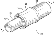
Fig. 9 and 10 shows the connector assembly 230 that comprises key 252 and mate chamber 290.Be endowed identical reference number and add " 200 " with the parts of connector assembly 230 corresponding to connector assembly 30.When key 252 was positioned in chamber 290, the user was in the not saturating fluid-tight of the interior foundation of connector assembly 230.Connector assembly 230 comprises the first adapter 236 and the second adapter 238.The first adapter 236 has the tubular attachment part 240 of the inside of the shell 241 that is fixed to the first adapter.Attachment portion 240 can be received in (second) pipeline 234 hermetically.The second adapter 238 has attachment portion 280, and this attachment portion can be attached to the second adapter (first) pipeline 232.The second adapter 238 comprises shell 281, and this shell is installed attachment portion by means of the flange 283 of attachment portion.The packing ring 276(that is installed by shell 281 broadly, " potted component ") be generally tubular and comprise the 276a of ear in the opening 277 that is received in the respective shapes in shell 281.Packing ring 276 is from the axial outer surface that upcountry is received in the external surface peripheral of attachment portion 280 and engages hermetically attachment portion 280 of mounting flange 283.
Coupling part 242 receives in packing ring 276 to form being tightly connected between the first and second adapters slidably and hermetically by the first end of the second adapter 238.Key 252 snaps fit onto to mate in chamber 290 and is tightly connected releasedly the first and second adapters 236,238 are locked into.In order to discharge the first adapter 236, the user presses down the button 286 with chimb, and from second adapter 238 tractive the first adapters 236, keeps simultaneously the second adapter 238.Push button 286 make the first adapter distortion and laterally shifting bond(s) 252 leave chamber 290.Key 252 prevents and is not suitable for engaging of adapter (not shown).
The optional embodiment with key connector assembly 530 shown in Figure 19 and 19A is similar to the band key connector assembly 230 of Fig. 9 and 10.Be endowed identical reference number and add " 500 " with the parts of connector assembly 530 corresponding to connector assembly 30.The first adapter 536 comprises key 552, guide rib 553 and comprises the interior tube chamber of rigidity or the pipeline 548 of attachment portion 540.The second adapter 538 comprises coupling chamber 590, interior potted component 588 and finger grip spare 578.The attachment portion 580 that is positioned at the second adapter 538 comprises the part 580a that is attached to hermetically potted component 588, and can be attached to the outer part 580b of pipeline (not shown).In operation, the user is the second adapter 538 promptly at finger grip spare 578 places, promptly the first adapter 536 and then 590 promote keys 552 until it snaps fit onto in the chamber towards the chamber.Flange 553 engages the second adapter 538 and helps the first adapter 536 is directed into and the second adapter sealed engagement.The inner of pipeline 548 be received in potted component 588 and by with potted component in annular outstanding 576 engages with potted component and seals.Like this, can form the first and second adapters 536,538 be tightly connected.
Figure 11-14 show the another optional embodiment of connector assembly 330.Add " 300 " indication with the parts of connector assembly 330 corresponding to connector assembly 30 by identical reference number.Connector assembly 330 comprises first adapter 336(Figure 13) and second adapter 338(Figure 14).The first adapter 336 has attachment portion 340(Figure 12), this attachment portion receives the pipeline (not shown) on the inner surface 341 of attachment portion 340.Second adapter 338(Figure 14) have attachment portion 380 at first end, and have cap 374 at the second end.The second pipeline (not shown) may be received on attachment portion 380.Deformable O shape ring the 376 and second end around the periphery of cap 374 is spaced a distance.O shape ring 376 is attached to cap 374 releasedly.Will be understood that, potted component forms in any suitable manner, for example the convex surfaces of O shape ring (as shown in the figure) or deformable plastic.
The first adapter 336 further comprises with at least one the vertical passage 372(Figure 13 by wherein) coupling part 342.A plurality of non-tight 352 zones, surface (Figure 12 and 13) are arranged on the inboard of coupling part 342.Non-tight surface 352 has the vertical passage 358 on the inner surface that is arranged in the first adapter 336, to prevent and the fluid-tight that is not suitable for adapter.Axially, vertical passage 358 also is arranged in and limits sealing surfaces 348(Figure 13) the both sides of groove 349 on.A plurality of vertical passage 372(Figure 13) be arranged on the face of coupling part 342.The open space that is limited by passage 372 prevents that coupling part 342 and the surface that is not suitable for adapter from forming fluid-tight.
In operation, the user is inserted in cap 374 in the opening of coupling part 342.Be deformed when being moved beyond non-tight surface 352 under the power effect of O shape ring 376 the user.O shape ring 376 stops in groove 349 and engages sealing surfaces 348(Figure 13) to form not fluid-tight thoroughly.
Figure 15-18 show the further embodiment of connector assembly 430.Be endowed identical reference number and add " 400 " with the parts of connector assembly 430 corresponding to connector assembly 30.Connector assembly 430 comprises the first adapter 436 and the second adapter 438.The first adapter 436 has attachment portion 440, and this attachment portion can be attached to the tube chamber (not shown) that is communicated with fluid source fluid ground.Tube chamber (or pipeline) be received on the outer surface of attachment portion 440 and with its formation fluid-tight thoroughly.The first adapter 436 has the coupling part 442 that comprises sealing surfaces 448 and a pair of non-tight surface 452, and vertical passage 458(Figure 17 of having on the interior and outer surface that is arranged in coupling part 442 of each non-tight surface 452).Vertical passage 458 is arranged on the either side of sealing surfaces 448.Vertical passage 458 prevents from being not suitable for the sealed engagement of adapter and coupling part 442.Vertical passage 458 can along the periphery of coupling part 442 be directed Anywhere and can the vicissitudinous length of tool, width or the degree of depth.Loop system moving part 479(is destroyed by passage 458 substantially) extend around the first adapter 436.
The second adapter 438 comprises attachment portion 480, cap 474, and O shape that hermetically be arranged on cap on inner at cap encircles 476, and deflection axle journal 477(Figure 16 and 18).In operation, the user shifts the second adapter 438 on coupling part 442 onto, and first surface 464 enters the opening of the second adapter 438 at deflection axle journal end.(leading) non-tights surface 452 and can not setting up due to passage 458 and being tightly connected of non-tight surface before O shape ring 476 engages.Then, when the first adapter 436 was advanced further in the second adapter 438 and sets up being tightly connected between the first and second adapters, O shape ring 476 engaged sealing surfaces 448.The brake component 479 of the first adapter 436 is received in annular groove 478 on the inboard of deflection axle journal 477.From the deflection axle journal of its slack position deflection against brake component 479 and hold them in groove 478, the first and second adapters 436,438 are fixed together being used for.
Figure 20-25 show the further embodiment of connector assembly 630.Be endowed identical reference number and add " 600 " with the parts of connector assembly 630 corresponding to connector assembly 30.Connector assembly 630 comprises the first adapter 636 and the second adapter 638.The first adapter 636 comprises the first shell 657, attachment portion 640 and coupling part 642, and the second adapter 638 comprises second housing 659, attachment portion 680 and accepter 678.The first and second shells 657,659 are removed to illustrate better the first and second adapters 636, other features of 638 in Figure 22 and 23.The first adapter 636 can with another object or equipment, for example the wall 643(of the shell of the controller of the controller shown in similar Figure 33 2 only shows local part) integrally formed or be fixed to another object or equipment.The pipeline (show, but be similar to medical pipeline 32) that attachment portion 640 receptions of the first adapter 636 are extended from the pump in controller.Yet attachment portion 640 can be directly connected to the object except pipeline.
With reference to Figure 22, the coupling part 642 of the first adapter 636 has first end 644 and the second end 646.The second end 646 for example is attached to attachment portion 640 suitably by solvent bonding or RF welding, perhaps can form with attachment portion the integral piece of material.Attachment portion 640 can be received in pipeline (for example pipeline 32(Figure 34 of pipe group 20) hermetically) in.Coupling part 642 comprises sealing surfaces 648 and non-tight surface 652.Non-tight surface 652 is than the free end of more close the first adapter 636 of sealing surfaces 648.Sealing surfaces 648 extends at the periphery of the second end 646 around coupling part 642.Embodiment shown in the shape of coupling part 642 and profile are not limited to, as long as coupling part can engage and form sealing with the second adapter 638, this will be described.Non-tight surface 652 has the diameter larger than sealing surfaces 648.A plurality of circle spacing passages 658 in non-tight surface 652 the first adapter 636 vertically on extend.Passage 658 operates to stop the formation that is tightly connected with the inner surface of medical pipeline.
The second adapter 638 has deformable O shape ring 663 at an end of the accepter 678 relative with attachment portion 680, and it is caught by cap 655.With reference now to Figure 23,, cap 655 is engaged on O shape ring 663 and carries out buckle with the tapered end 665 of accepter 678 and is connected that O shape ring is captured between the face 667 of cap and accepter.In case be hunted down, O shape ring 663 is from radially inwardly outstanding between the end face 667 of accepter 678 and cap 655, makes that O shape is encircled the sealing surfaces 648 that can engage hermetically the first adapter 636 when the first adapter 636 is received in the second adapter 638.The attachment portion 680 of the second adapter 638 on diameter in the middle of it convergent so that the second connector assembly 639 promptly.Attachment portion 680 can receive general pipeline (for example pipeline 32(Figure 34 of pipe group 20) hermetically).
Comprise the key 611 with outstanding element 621 with reference to Figure 20 and 21, the second adapters 638.The first adapter 636 comprise the coupling chamber 613.In order to form the sealing between the first adapter 636 and the second adapter 638, the first end 644 that the user must promote the first adapter is by O shape ring 663 and enter the accepter 678 of the second adapter 638, makes non-tight surface 652 cross O shape ring.Reach such degree in the key 611 of the second adapter 638639 is positioned at the coupling chamber 613 of the first adapter 636, when making outstanding element 621 in abutting connection with the first shell 657, sealing surfaces 648 engages O shapes ring 663.The adjacency of outstanding element 621 and the first shell 657 prevents separating of the first adapter 636 and the second adapter 638.In order to discharge the second adapter 638, the user presses down outstanding element 621 and from second adapter 638 tractive the first adapters 636, keeps simultaneously the second adapter.Pressing down outstanding element 621 will give prominence to element and move to outside coupling chamber 613.
The first shell 657 with reference to Figure 24 and 25, the first adapters 636 comprises base plate 671.Coupling part 642 is outwards outstanding from base plate 671.From shell bottom plate 671 outwards outstanding perpendicular rib 675 around coupling part 642 interval circumferentially.Be attached to circumferentially linkage section 681 around coupling part near the end of each perpendicular rib 675 of coupling part 642.Usually 679 the indication passing aways be limited on linkage section 681 and rib 675 and base plate 671 between.Allow fluid discharging around coupling part when preventing not thoroughly fluid-tight when pipeline is inserted on coupling part 642 fully, passing away 679 extends through pipeline, for example the end face of common therapy pipeline.Direction and the path of flowing (Figure 25) are indicated by arrow " A " usually.When the end face of medical pipeline was pushed in the first shell 657 as shown in Figure 25 always, passing away 679 prevented coupling part and medical pipeline MT(" non-permission pipeline ") between smoothly thoroughly fluid connect.In this case, Typical Controller can sense does not have saturating fluid to connect and starts alarm.
Figure 26 and 27 shows the further embodiment of the first adapter 736.To be endowed identical reference number and add " 100 " with the parts of the first adapter 736 corresponding to adapter 636.Passing away 779 is formed in the first adapter 736 and usually is oriented to the base plate 771 of close shell 757, to be used for discharging fluid around coupling part 742.With reference now to Figure 26,, passing away 779 radially outward opens wide and axially extends through shell bottom plate 771 at the first opening from coupling part 742, opens wide from the first adapter in a side of the base plate relative with the first opening.The non-tight surface 752 of coupling part 742 prevents conventional medical pipeline MT(" non-permission pipeline ") with the sealing of sealing surfaces 748.The end face of pipeline MT can form sealing with base plate 771.Yet the passing away 779 that is formed in sealing surfaces 748 is not sealed.Therefore, the air in medical pipeline MT can pass the passage 758 in non-tight surface 752 and leave passing away 779 as arrow " B " as shown in (Figure 27) along sealing surfaces 748.So, can form non-not saturating fluid with standard medical pipeline MT and be connected, even the end face of pipeline forms sealing with other mode and base plate 771.
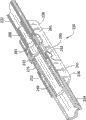
Figure 28-31 show the further embodiment of connector assembly 830.Be endowed identical reference number and add " 800 " with the parts of connector assembly 830 corresponding to connector assembly 30.Connector assembly 830 comprises the first adapter 836 and second adapter 838(Figure 28 and 29).The first adapter 836 has tubulose and hook-shaped attachment portion 840, and this attachment portion is fixed to the grip portion 841 of the first adapter and is positioned at the inside (Figure 30) of grip portion.Attachment portion 840 can be received in pipeline 834 hermetically.Yet to be directly connected to the identical mode of controller 2 with the 3rd adapter 10, attachment portion 840 can be directly connected to the object except pipeline.The second adapter 838 has can be attached to the second adapter pipeline 32(Figure 34 that general pipeline 832(for example is similar to pipe group 20)) attachment portion 880.
The second adapter 838 comprises accepter 878.Accepter 878 is installed to attachment portion 880 by means of flange 883.Accepter 878 have inner surface 874 and at annular shoulder 875(Figure 30 of the inner of the inside of accepter).Shoulder 875 limits stop surfaces, and this stop surfaces restriction first adapter 836 can insert the distance in accepter 878 and axially locate the first adapter 836 with respect to accepter 878.
The surface of the surface of the grip portion 841 of the first adapter 836 and the attachment portion 880 of the second adapter 838 comprises ridge 814,824.The ridge 814 of the first adapter 836 comprise substantially relative bracket the first ridge 814a of vertical upwardly extending two cardinal principles of the first adapter and on the first adapter vertical interval and the second ridge 814b(Figure 28 of two flat U-shapeds between the first ridge).Similarly, ridge 824 comprise with the mode identical with the second ridge 814b with the first ridge 814a be shaped and the first ridge 824a of arranging and the second ridge 824b(referring to Figure 29).In the embodiment shown, the first and second ridge 814a, 814b and 824a, 824b are arranged to limit the passages 822,828 that are respectively used to pass through along adapter 836,838 air.Usually prevent from forming fluid-tight thoroughly at 814 and 824 ridges of indicating when the common therapy pipeline is placed on surface grip portion 841 or attachment portion 880 respectively.If such pipeline (not shown) is placed on adapter, the passage 822 that is limited by ridge 814,824,828 is along carrying fluid by arrow " A " indicated direction leaves adapter 836,838 substantially, stop thus adapter 836,838 with the saturating fluid-tight of medical pipeline.The second ridge 814b, 824b help prevent the sealing between highly consistent tube material and the first ridge 814a, 824b.
Be to be understood that within the scope of the invention ridge 814 and 824 can have be different from shown in and configurations differing from one and layout.When being formed in embodiment as shown and arranging, ridge 814,824 provides the passage of air, but also is convenient to promptly adapter 836,838.In the embodiment shown, have resemble the ridge 814 that to see, 824 ridge (not shown) in Figure 28 and 29, but it is positioned at adapter 836,838 opposite side.
With reference to Figure 28, the grip portion 841 of the first adapter 836 has the flange 815 that forms at far-end.The first adapter 836 comprises coupling part 842 and base plate 871.The diameter of base plate 871 is substantially identical with the diameter of flange 815.The passing away 817 that base plate 871 and flange 815 are included in their periphery prevents not fluid-tight thoroughly with time on the periphery that is placed on flange and base plate when medical pipeline.Another that is similar to passing away 817 is positioned at the opposite side of adapter 836 to the passing away (not shown).Will be understood that any amount of passing away can be used in scope of the present invention.
The first adapter 836 comprises the coupling part 842 of outwards giving prominence to from base plate 871.From base plate 871 outwards outstanding perpendicular rib 875 around coupling part 842 interval circumferentially.Usually the passing away in 879 indications is limited between rib 875 and base plate 871.Passing away 879 caves in and is communicated with passing away 817 from rib 875.If too little so that can not receive therein the medical tube MT of whole adapter 836 and be pulled to as shown in Figure 31 on coupling part 842, an end engage ribs 875 of pipeline and keep separating base plate 871.Air can effuser, enters passing away 879 and arrives passing aways 817 or radially outward be directed from the first adapter 836.The direction that flows and path are substantially by arrow " A " indication (Figure 31).When the end face of medical pipeline was pulled to base plate 871 always, passing away 817,879 prevented the not fluid connection thoroughly smoothly between coupling part 842 and medical pipeline.
Coupling part 842 comprises sealing surfaces 848 and non-tight surface 852.The free end of non-tight surface ratio sealing surfaces 848 more close the first adapters 836.Sealing surfaces extends around the periphery of coupling part 842.Shape in embodiment shown in the shape of coupling part 842 and profile are not limited to and profile, as long as coupling part can engage and form sealing with the second adapter 838, this will be described.Non-tight surface 852 has the diameter larger than sealing surfaces 848.A plurality of circle spacing passages 858 in non-tight surface 852 the first adapter 836 vertically on extend.Passage 858 operates to stop coupling part 842 and the inner surface formation of medical pipeline to be tightly connected.
The second adapter 838 has deformable O shape ring 863 at an end of the accepter 878 relative with attachment portion 880.O shape ring 863 is radially inwardly given prominence to and axially is positioned such that when the first adapter 836 is received in the second adapter 838, and O shape ring can engage the sealing surfaces 848 of the first adapter 836 hermetically to form not fluid-tight thoroughly.Like this, basically, only allow expection to connect.
For preferred embodiment described here, adapter is by the half flexible and flexible material that is suitable for vascular compression treatment, for example polymeric material manufacturing, and this depends on that specific vascular treatment uses and/or preference.Can use urethanes and silicon.Yet, according to the disclosure, person of skill in the art will appreciate that the other materials and the manufacture method that are suitable for assembling and making are also suitable.The size and dimension that depends on connector assembly, a plurality of replacement seal and non-tight surface are possible.
When introducing the element of the present invention or its preferred (one or more) embodiment, article " " and " described " mean that expression has one or more elements.Term " comprises ", " comprising " and " having " mean the add ons that comprises and represent to have except listing element.
In view of above content, it will be appreciated that and realized several target of the present invention and obtained other favourable results.
Do not depart from the scope of the present invention owing to carrying out various variations in above embodiment and method, this means that being included in all the elements that above description neutralization shows in the accompanying drawings is appreciated that exemplary is not limited significance.
Claims (10)
1. electrical connector comprises:
The first adapter, it has shell, attachment portion and coupling part, and this coupling part comprises key; And
The second adapter, it has shell and attachment portion, and the shell of this second adapter has the coupling chamber that is formed at wherein, and when the first adapter and the second adapter mated with sealing relationship, this coupling chamber was used for catching the key of the first adapter.
2. electrical connector as claimed in claim 1, wherein should coupling the chamber towards the outside of electrical connector opening laterally, this first adapter comprises button part, and push button partly make the first adapter distortion and laterally mobile this key leave this coupling chamber.
3. electrical connector as claimed in claim 1, wherein when the first adapter and the second adapter are trapped in this coupling chamber with sealing relationship coupling and this key, this key laterally flushes with the shell of the second adapter with this coupling chamber.
4. pipe group, it comprises electrical connector as claimed in claim 1, and described pipe group comprises pipe, and the first adapter is connected to this pipe at its first end, and the second adapter is connected to this pipe at its second end.
5. system that is used for providing vascular compression, it comprises controller, pipe group and compression therapy device, wherein this controller is connected electrical connector and is connected with Guan Zuyu, and/or, this pipe group is connected with electrical connector as claimed in claim 1 with compression therapy device.
6. electrical connector comprises:
The first adapter, it has shell, attachment portion and coupling part, and described coupling part comprises three basic straight flange and the sealing surfaces between first end and the second end at least; With
The second adapter, it has shell and attachment portion, the shell of this second adapter is defined for the accepter that receives the first adapter, this accepter has the straight flange of three basic at least of shaping corresponding to the shape of the first adapter, the shell of this second adapter further has the non-tight surface at the opening of accepter, this non-tight surface is outwards launched and has therein at least one passage towards this end of shell, in order to stop the fluid-tight engagement thoroughly with the non-tight surface.
7. electrical connector as claimed in claim 6, wherein the non-tight surface of the second adapter is limited by sealing flange.
8. electrical connector as claimed in claim 7, the sealing surfaces of wherein said the first adapter comprises the described straight flange of three basic at least, the sealing flange of described the second adapter is elastic, and insert in the accepter of the second adapter and sealing surfaces when crossing the non-tight surface at the first adapter, the sealing flange of described the second adapter is suitable for being consistent to form fluid-tight thoroughly with the sealing surfaces of the first adapter.
9. pipe group, it comprises electrical connector as claimed in claim 6, and described pipe group comprises pipe, and the first adapter is connected to this pipe at its first end, and the second adapter is connected to this pipe at its second end.
10. system that is used for providing vascular compression, it comprises controller, pipe group and compression therapy device, wherein this controller is connected electrical connector and is connected with Guan Zuyu, and/or, this pipe group is connected with electrical connector as claimed in claim 6 with compression therapy device.
Applications Claiming Priority (4)
| Application Number | Priority Date | Filing Date | Title |
|---|---|---|---|
| US11/533,924 | 2006-09-21 | ||
| US11/533,924 US8257286B2 (en) | 2006-09-21 | 2006-09-21 | Safety connector apparatus |
| US11/852,841 | 2007-09-10 | ||
| US11/852,841 US8287517B2 (en) | 2006-09-21 | 2007-09-10 | Safety connector assembly |
Related Parent Applications (1)
| Application Number | Title | Priority Date | Filing Date |
|---|---|---|---|
| CN200780001149XA Division CN101405050B (en) | 2006-09-21 | 2007-09-21 | Safety connector assembly |
Publications (1)
| Publication Number | Publication Date |
|---|---|
| CN103120828A true CN103120828A (en) | 2013-05-29 |
Family
ID=38686770
Family Applications (3)
| Application Number | Title | Priority Date | Filing Date |
|---|---|---|---|
| CN2011102357005A Pending CN102430196A (en) | 2006-09-21 | 2007-09-21 | Safety connector assembly |
| CN200780001149XA Expired - Fee Related CN101405050B (en) | 2006-09-21 | 2007-09-21 | Safety connector assembly |
| CN2013100518891A Pending CN103120828A (en) | 2006-09-21 | 2007-09-21 | Safety connector assembly |
Family Applications Before (2)
| Application Number | Title | Priority Date | Filing Date |
|---|---|---|---|
| CN2011102357005A Pending CN102430196A (en) | 2006-09-21 | 2007-09-21 | Safety connector assembly |
| CN200780001149XA Expired - Fee Related CN101405050B (en) | 2006-09-21 | 2007-09-21 | Safety connector assembly |
Country Status (11)
| Country | Link |
|---|---|
| US (4) | US8257286B2 (en) |
| EP (5) | EP2233171A1 (en) |
| JP (2) | JP5189336B2 (en) |
| CN (3) | CN102430196A (en) |
| AU (1) | AU2007216937B2 (en) |
| BR (1) | BRPI0704452A (en) |
| CA (2) | CA2601496C (en) |
| IL (5) | IL223173A0 (en) |
| MX (1) | MX2009003000A (en) |
| NZ (1) | NZ561616A (en) |
| WO (1) | WO2008036935A2 (en) |
Families Citing this family (133)
| Publication number | Priority date | Publication date | Assignee | Title |
|---|---|---|---|---|
| US8257286B2 (en) | 2006-09-21 | 2012-09-04 | Tyco Healthcare Group Lp | Safety connector apparatus |
| US9642759B2 (en) | 2007-04-13 | 2017-05-09 | Stryker Corporation | Patient support with universal energy supply system |
| US8647300B2 (en) * | 2007-10-30 | 2014-02-11 | Medela Holding Ag | Device for connecting a suction hose |
| US8257287B2 (en) | 2008-03-20 | 2012-09-04 | Tyco Healthcare Group Lp | Safety connector assembly |
| EP2140905B1 (en) * | 2008-06-30 | 2011-08-17 | Tyco Healthcare Group LP | Discriminating Oral Tip Adaptor |
| US9903371B2 (en) * | 2008-09-17 | 2018-02-27 | Resmed Limited | Cuff for air delivery conduit |
| USD628288S1 (en) | 2009-01-22 | 2010-11-30 | Resmed Limited | Cuff for air delivery tube |
| JP5570534B2 (en) | 2009-03-06 | 2014-08-13 | サノフィ−アベンティス・ドイチュラント・ゲゼルシャフト・ミット・ベシュレンクテル・ハフツング | Syringe, self-injection device, and set of self-injection device and syringe |
| US8684979B2 (en) * | 2009-05-11 | 2014-04-01 | Covidien Lp | Discriminating fluid connection system |
| USD742508S1 (en) | 2013-07-12 | 2015-11-03 | Resmed Limited | Air delivery tube with cuff |
| EP2292294B1 (en) * | 2009-09-04 | 2017-08-23 | Dentsply IH AB | Catheter with customizable connector |
| CN201492465U (en) * | 2009-09-30 | 2010-06-02 | 孙东 | Compressive hemostasis device |
| JP5818401B2 (en) * | 2009-10-29 | 2015-11-18 | 株式会社トップ | Tubular member and tubular member for medical device |
| US9814870B2 (en) * | 2010-08-17 | 2017-11-14 | Becton, Dickinson And Company | Non-luer connectors |
| BRPI1004442A2 (en) * | 2010-09-10 | 2013-01-15 | Andrade Jose Bernardo Carvalho De | device for treating female urinary incontinence |
| IT1403142B1 (en) * | 2010-11-19 | 2013-10-04 | Borla Ind | MIXING DEVICE FOR MEDICAL FLUIDS AND ITS ASSEMBLY PROCEDURE. |
| US8864708B1 (en) | 2010-12-03 | 2014-10-21 | Medical Device Engineering, LLC. | Tamper indicating closure assembly |
| US8613762B2 (en) | 2010-12-20 | 2013-12-24 | Medical Technology Inc. | Cold therapy apparatus using heat exchanger |
| WO2012106613A1 (en) * | 2011-02-04 | 2012-08-09 | Merit Medical Systems, Inc. | Gas adaptor and method of use |
| DE102011011762B4 (en) * | 2011-02-18 | 2019-02-21 | Geuder Aktiengesellschaft | Luer connection as a connection system for medical cables |
| CN103458957B (en) | 2011-03-24 | 2016-01-06 | 泰尔茂株式会社 | Connector device part, Male Connector and Female Connector |
| US20130197536A1 (en) * | 2011-04-07 | 2013-08-01 | Jai Singh | General uterine manipulator and system |
| US9987042B2 (en) * | 2011-04-07 | 2018-06-05 | Jai Singh | General uterine manipulator and system |
| US9451985B2 (en) | 2011-04-07 | 2016-09-27 | Jiwan Steven Singh | General uterine manipulator and system |
| US8764789B2 (en) * | 2011-04-15 | 2014-07-01 | CellAegis Devices Inc. | System for performing remote ischemic conditioning |
| CN102758819A (en) * | 2011-04-28 | 2012-10-31 | 泰科电子(上海)有限公司 | Connecting device |
| GB2505132A (en) * | 2011-06-08 | 2014-02-19 | Nxstage Medical Inc | Methods, devices, and systems for coupling fluid lines |
| WO2013002655A2 (en) * | 2011-06-28 | 2013-01-03 | Fisher & Paykel Healthcare Limited | Improved medical tubing |
| WO2013000464A1 (en) * | 2011-06-28 | 2013-01-03 | Safeair Ag | An elongated electrosurgical instrument, a suction tip for the electrosurgical instrument and method of adjusting the axial position of the suction tip on the electrosurgical instrument |
| GB2494453B (en) * | 2011-09-12 | 2013-08-07 | Owen Mumford Ltd | Injector assembly |
| MX343467B (en) | 2011-09-22 | 2016-11-07 | Abbvie Inc | Automatic injection device. |
| RU2620351C2 (en) | 2011-09-22 | 2017-05-24 | Эббви Инк. | Automated injector |
| JP5422634B2 (en) * | 2011-11-18 | 2014-02-19 | 富士フイルム株式会社 | Endoscope insertion aid and endoscope system |
| US10070990B2 (en) * | 2011-12-08 | 2018-09-11 | Alcon Research, Ltd. | Optimized pneumatic drive lines |
| US9566187B2 (en) | 2012-03-13 | 2017-02-14 | Breg, Inc. | Cold therapy systems and methods |
| US9114055B2 (en) | 2012-03-13 | 2015-08-25 | Cothera Llc | Deep vein thrombosis (“DVT”) and thermal/compression therapy systems, apparatuses and methods |
| AU2013232848B2 (en) | 2012-03-15 | 2018-03-22 | Fisher & Paykel Healthcare Limited | Respiratory gas humidification system |
| AU2013249076B2 (en) | 2012-04-20 | 2018-03-29 | Jai Singh | Repositionable medical instrument support systems, devices, and methods |
| EP2841137B1 (en) | 2012-04-27 | 2019-12-25 | Fisher & Paykel Healthcare Limited | Usability features for respiratory humidification system |
| US9402763B2 (en) | 2012-09-12 | 2016-08-02 | Breg, Inc. | Cold therapy apparatus having heat exchanging therapy pad |
| US9901725B2 (en) | 2012-10-01 | 2018-02-27 | Bayer Healthcare Llc | Overmolded medical connector tubing and method |
| WO2014116122A1 (en) * | 2013-01-22 | 2014-07-31 | Fisher & Paykel Healthcare Limited | Dual-connector wye piece |
| US10207096B2 (en) | 2013-02-27 | 2019-02-19 | Fresenius Medical Care Holdings, Inc. | Fluid line connectors |
| US10022301B2 (en) | 2013-03-15 | 2018-07-17 | Becton Dickinson and Company Ltd. | Connection system for medical device components |
| AU2013203746B2 (en) | 2013-03-15 | 2015-05-07 | Cellaegis Devices, Inc. | Gas Powered System for Performing Remote Ischemic Conditioning |
| US9414990B2 (en) | 2013-03-15 | 2016-08-16 | Becton Dickinson and Company Ltd. | Seal system for cannula |
| US9713563B2 (en) * | 2013-03-15 | 2017-07-25 | Compression Therapy Concepts, Inc. | Micro bleed hole connector for use in intermittent pneumatic compression devices |
| DE102013106550A1 (en) * | 2013-06-24 | 2014-12-24 | B. Braun Avitum Ag | Luer lock connector with grooves |
| ITTO20130636A1 (en) * | 2013-07-29 | 2015-01-30 | Avio Spa | TRANSMISSION BOX, AND DISASSEMBLY METHOD TO DISCONNECT A DRIVE SHAFT IN SUCH A TRANSMISSION BOX |
| CN108704213B (en) * | 2013-09-13 | 2021-06-22 | 费雪派克医疗保健有限公司 | Connection for humidification system |
| GB2584025B (en) | 2013-09-13 | 2021-03-10 | Fisher & Paykel Healthcare Ltd | Heater plate for a humidification system |
| US9534721B2 (en) | 2013-10-31 | 2017-01-03 | Nordson Corporation | High pressure fluid conduit connector components and connector assembly |
| USD743510S1 (en) | 2013-10-31 | 2015-11-17 | Nordson Corporation | High pressure fluid conduit connector components and connector assembly |
| US9636278B2 (en) | 2013-11-06 | 2017-05-02 | Becton Dickinson and Company Limited | System for closed transfer of fluids with a locking member |
| CN105848707B (en) | 2013-11-06 | 2020-06-16 | 贝克顿·迪金森有限公司 | Medical connector with locking engagement |
| US10286201B2 (en) | 2013-11-06 | 2019-05-14 | Becton Dickinson and Company Limited | Connection apparatus for a medical device |
| DE102013018639A1 (en) * | 2013-11-06 | 2014-07-24 | Fresenius Medical Care Deutschland Gmbh | Connector for connecting bag and hose system for providing e.g. medical solution during extraporal blood treatment for patient, has cone only opening sealing element when projection of one part is inserted in retainer of other part |
| CN105792793B (en) | 2013-11-06 | 2020-08-14 | 贝克顿·迪金森有限公司 | Liquid-tight transfer system with connector |
| DE112014005831T5 (en) | 2013-12-20 | 2016-09-15 | Fisher & Paykel Healthcare Limited | Befeuchtungssystemverbindungen |
| US10912898B1 (en) | 2014-02-03 | 2021-02-09 | Medical Device Engineering Llc | Tamper evident cap for medical fitting |
| US10449319B2 (en) | 2014-02-07 | 2019-10-22 | Fisher & Paykel Healthcare Limited | Respiratory humidification system |
| US10207099B1 (en) | 2014-02-21 | 2019-02-19 | Patrick Vitello | Closure assembly for medical fitting |
| USD762843S1 (en) | 2014-03-18 | 2016-08-02 | Resmed Limited | Air delivery tube |
| WO2015161047A1 (en) | 2014-04-16 | 2015-10-22 | Becton Dickinson and Company Limited | Fluid transfer device with axially and rotationally movable portion |
| CN109771280B (en) | 2014-04-21 | 2021-12-14 | 贝克顿迪金森有限公司 | System with adapter for the closed transfer of fluids |
| ES2948711T3 (en) | 2014-04-21 | 2023-09-18 | Becton Dickinson & Co Ltd | Syringe adapter with combined decoupling motion |
| AU2015249915B2 (en) | 2014-04-21 | 2017-11-30 | Becton Dickinson and Company Limited | System for closed transfer of fluids |
| US9833605B2 (en) | 2014-04-21 | 2017-12-05 | Becton Dickinson and Company Limited | Fluid transfer device and packaging therefor |
| CN110368302B (en) | 2014-04-21 | 2023-03-10 | 贝克顿迪金森有限公司 | Diaphragm device for use with closed system transfer device |
| CN110353993B (en) | 2014-04-21 | 2022-04-12 | 贝克顿迪金森有限公司 | Bottle stabilizer base with attachable bottle adapter |
| EP3134052B1 (en) | 2014-04-21 | 2022-08-03 | Becton Dickinson and Company Limited | Syringe adapter with disconnection feedback mechanism |
| JP6449910B2 (en) | 2014-04-21 | 2019-01-09 | ベクトン ディキンソン アンド カンパニー リミテッド | Fluid transfer device and packaging thereof |
| US11173272B2 (en) | 2014-05-02 | 2021-11-16 | Fisher & Paykel Healthcare Limited | Gas humidification arrangement |
| US10709866B2 (en) | 2014-05-13 | 2020-07-14 | Fisher & Paykel Healthcare Limited | Usability features for respiratory humidification system |
| US11324911B2 (en) | 2014-06-03 | 2022-05-10 | Fisher & Paykel Healthcare Limited | Flow mixers for respiratory therapy systems |
| GB201411370D0 (en) | 2014-06-26 | 2014-08-13 | Huntleigh Technology Ltd | Inflation pressure garments and connectors |
| US10166347B1 (en) | 2014-07-18 | 2019-01-01 | Patrick Vitello | Closure assembly for a medical device |
| US10718454B2 (en) | 2014-11-10 | 2020-07-21 | Specified Medical Technologies, LLC | Oxygen supply quick connect adapter |
| US11278689B2 (en) | 2014-11-17 | 2022-03-22 | Fisher & Paykel Healthcare Limited | Humidification of respiratory gases |
| US10300263B1 (en) | 2015-02-27 | 2019-05-28 | Timothy Brandon Hunt | Closure assembly for a medical connector |
| US10238854B2 (en) | 2015-03-12 | 2019-03-26 | Teknor Apex Company | Methods for forming a tube assembly utilizing a joining agent |
| US10166343B1 (en) | 2015-03-13 | 2019-01-01 | Timothy Brandon Hunt | Noise evident tamper cap |
| US10315024B1 (en) | 2015-03-19 | 2019-06-11 | Patick Vitello | Torque limiting closure assembly |
| JP1567037S (en) * | 2015-07-20 | 2017-01-16 | ||
| USD779662S1 (en) * | 2015-08-07 | 2017-02-21 | Laborie Medical Technologies, Corp. | Female catheter connector |
| US10322247B1 (en) * | 2015-10-01 | 2019-06-18 | John C. Radcliffe, Jr. | Intravenous therapy tubing connection system |
| AU2016362516A1 (en) * | 2015-12-04 | 2018-07-19 | Kpr U.S., Llc | High-flow enteral feeding syringe assembly |
| WO2017100621A1 (en) | 2015-12-11 | 2017-06-15 | Nxstage Medical, Inc. | Fluid line connector devices methods and systems |
| US10667984B2 (en) | 2015-12-18 | 2020-06-02 | Stryker Corporation | Systems and methods for operating patient therapy devices |
| US9869416B2 (en) | 2016-01-26 | 2018-01-16 | Tectran Mfg. Inc. | Swivel coupling and hose assemblies and kits utilizing the same |
| US9759359B2 (en) | 2016-01-26 | 2017-09-12 | Tectran Mfg. Inc. | Grip and fitting assemblies and kits utilizing the same |
| USD805630S1 (en) | 2016-02-02 | 2017-12-19 | Resmed Limited | Air delivery tube |
| USD818587S1 (en) | 2016-03-29 | 2018-05-22 | Abbevie Inc. | Automatic injection device |
| JP2017202231A (en) * | 2016-05-13 | 2017-11-16 | 学校法人北里研究所 | Hemostatic compression device with wrong connection prevention mechanism |
| WO2018022194A1 (en) * | 2016-07-28 | 2018-02-01 | Commscope Technologies Llc | Self-sealing hybrid power/fiber connector |
| SG10202106016TA (en) | 2016-12-07 | 2021-07-29 | Fisher and paykel healthcare ltd | Sensing arrangements for medical devices |
| US10307548B1 (en) | 2016-12-14 | 2019-06-04 | Timothy Brandon Hunt | Tracking system and method for medical devices |
| US11097071B1 (en) | 2016-12-14 | 2021-08-24 | International Medical Industries Inc. | Tamper evident assembly |
| US10953162B1 (en) | 2016-12-28 | 2021-03-23 | Timothy Brandon Hunt | Tamper evident closure assembly |
| US10758684B1 (en) | 2017-03-03 | 2020-09-01 | Jonathan J. Vitello | Tamper evident assembly |
| JP6995834B2 (en) * | 2017-03-16 | 2022-01-17 | テルモ株式会社 | Medical equipment |
| US11040149B1 (en) | 2017-03-30 | 2021-06-22 | International Medical Industries | Tamper evident closure assembly for a medical device |
| US10888672B1 (en) | 2017-04-06 | 2021-01-12 | International Medical Industries, Inc. | Tamper evident closure assembly for a medical device |
| US10898659B1 (en) | 2017-05-19 | 2021-01-26 | International Medical Industries Inc. | System for handling and dispensing a plurality of products |
| US10933202B1 (en) | 2017-05-19 | 2021-03-02 | International Medical Industries Inc. | Indicator member of low strength resistance for a tamper evident closure |
| US10743670B2 (en) * | 2017-05-23 | 2020-08-18 | Yeti Coolers, Llc | Portable chair and cup holder assembly |
| US10561249B2 (en) | 2017-05-23 | 2020-02-18 | Yeti Coolers, Llc | Portable chair and cup holder assembly |
| US11541180B1 (en) | 2017-12-21 | 2023-01-03 | Patrick Vitello | Closure assembly having a snap-fit construction |
| USD850810S1 (en) | 2018-01-10 | 2019-06-11 | Yeti Coolers, Llc | Portable chair |
| US11278681B1 (en) | 2018-02-20 | 2022-03-22 | Robert Banik | Tamper evident adaptor closure |
| USD856091S1 (en) * | 2018-02-23 | 2019-08-13 | Yeti Coolers, Llc | Cup holder |
| US20190269069A1 (en) * | 2018-03-02 | 2019-09-05 | Tti (Macao Commercial Offshore) Limited | Coupler for a tool |
| US11413406B1 (en) | 2018-03-05 | 2022-08-16 | Jonathan J. Vitello | Tamper evident assembly |
| US11779520B1 (en) | 2018-07-02 | 2023-10-10 | Patrick Vitello | Closure for a medical dispenser including a one-piece tip cap |
| US11857751B1 (en) | 2018-07-02 | 2024-01-02 | International Medical Industries Inc. | Assembly for a medical connector |
| US11793987B1 (en) | 2018-07-02 | 2023-10-24 | Patrick Vitello | Flex tec closure assembly for a medical dispenser |
| USD890102S1 (en) * | 2018-07-11 | 2020-07-14 | Karim Messadek | Female connector |
| US11690994B1 (en) | 2018-07-13 | 2023-07-04 | Robert Banik | Modular medical connector |
| US11426328B1 (en) | 2018-08-31 | 2022-08-30 | Alexander Ollmann | Closure for a medical container |
| WO2020061280A2 (en) * | 2018-09-19 | 2020-03-26 | Deroyal Industries, Inc. | Tubing connection system for negative pressure wound therapy |
| US11471610B1 (en) | 2018-10-18 | 2022-10-18 | Robert Banik | Asymmetrical closure for a medical device |
| USD948713S1 (en) | 2019-09-03 | 2022-04-12 | International Medical Industries, Inc. | Asymmetrical self righting tip cap |
| US10998665B2 (en) | 2018-11-15 | 2021-05-04 | Medline Industries, Inc. | Hybrid connector |
| USD903865S1 (en) | 2018-11-19 | 2020-12-01 | International Medical Industries, Inc. | Self-righting tip cap |
| US11911339B1 (en) | 2019-08-15 | 2024-02-27 | Peter Lehel | Universal additive port cap |
| US11697527B1 (en) | 2019-09-11 | 2023-07-11 | Logan Hendren | Tamper evident closure assembly |
| US11357588B1 (en) | 2019-11-25 | 2022-06-14 | Patrick Vitello | Needle packaging and disposal assembly |
| GB2590977B (en) * | 2020-01-13 | 2024-02-14 | Gbuk Group Ltd | Lockable adapter assembly |
| US11904149B1 (en) | 2020-02-18 | 2024-02-20 | Jonathan Vitello | Oral tamper evident closure with retained indicator |
| US11523970B1 (en) | 2020-08-28 | 2022-12-13 | Jonathan Vitello | Tamper evident shield |
| CN112536810B (en) * | 2020-12-16 | 2021-09-24 | 黑龙江职业学院(黑龙江省经济管理干部学院) | Robot quick connector containing multiple process free-set joint freedom degrees |
| US11872187B1 (en) | 2020-12-28 | 2024-01-16 | Jonathan Vitello | Tamper evident seal for a vial cover |
| CN113181507B (en) * | 2021-04-19 | 2023-03-14 | 贵州中医药大学第一附属医院 | Device for connecting port of end-expiratory carbon dioxide detector with port of gastric tube and connection sealing method thereof |
Citations (6)
| Publication number | Priority date | Publication date | Assignee | Title |
|---|---|---|---|---|
| WO1981000053A1 (en) * | 1979-07-04 | 1981-01-22 | Travenol Lab Pty Ltd | Sterile fluid line coupling members |
| US5190534A (en) * | 1990-12-07 | 1993-03-02 | Delmed, Inc. | Prefilled sterilant fluid releasable coupling connector apparatus for catheter applications |
| US5725485A (en) * | 1994-04-05 | 1998-03-10 | Beiersdorff Jobst, Inc. | Connector for a gradient sequential compression system |
| EP0880978A2 (en) * | 1993-08-24 | 1998-12-02 | B. Braun Melsungen Ag | Tube coupling |
| CN2461587Y (en) * | 2000-01-12 | 2001-11-28 | 李汉斌 | Detatachable tube assembly |
| CN2519668Y (en) * | 2001-12-07 | 2002-11-06 | 李国荣 | Thorax moving asistant physical therapy instrument |
Family Cites Families (188)
| Publication number | Priority date | Publication date | Assignee | Title |
|---|---|---|---|---|
| US2280485A (en) | 1942-04-21 | Calculating device | ||
| US1614815A (en) * | 1925-06-25 | 1927-01-18 | Guiberson Corp | Tubular coupling |
| US2257321A (en) * | 1939-04-14 | 1941-09-30 | Mathew H Arnold | Coupling |
| US2694395A (en) | 1951-05-10 | 1954-11-16 | William J Brown | Pneumatic pressure garment |
| US2694393A (en) | 1951-07-11 | 1954-11-16 | William E Simpson | Weed burner |
| US2893395A (en) | 1957-02-08 | 1959-07-07 | Becton Dickinson Co | Medical assembly and unit for liquid transfer |
| FR1171861A (en) | 1957-04-24 | 1959-01-30 | Improvements to closed-circuit anesthesia machines | |
| US3057001A (en) | 1958-06-23 | 1962-10-09 | Illinois Tool Works | Strain relief grommet |
| US3097866A (en) * | 1960-11-14 | 1963-07-16 | Weatherhead Co | Pressurized hose end |
| US3287031A (en) * | 1964-09-21 | 1966-11-22 | William H Simmons | Indexed keyed connection |
| US3454006A (en) | 1966-01-28 | 1969-07-08 | Weck & Co Inc Edward | Intravenous catheter-needle assembly provided with needle bushing guide |
| US3625212A (en) | 1969-07-09 | 1971-12-07 | North American Biolog Inc | Eliminating mistakes in plasmapheresis |
| IL36081A (en) | 1970-02-16 | 1973-11-28 | Bunker Ramo | An electrical two-part connector |
| US3728875A (en) | 1971-01-07 | 1973-04-24 | Kendall & Co | Stocking with soft inner thigh area |
| US3834388A (en) | 1973-01-29 | 1974-09-10 | Cenco Medical Health Supply Co | Suction control arrangement for a suction catheter |
| US4066084A (en) | 1974-01-14 | 1978-01-03 | Hans Tillander | Blood emptying device |
| US4029087A (en) | 1975-10-28 | 1977-06-14 | The Kendall Company | Extremity compression device |
| US4030488A (en) | 1975-10-28 | 1977-06-21 | The Kendall Company | Intermittent compression device |
| US4013069A (en) | 1975-10-28 | 1977-03-22 | The Kendall Company | Sequential intermittent compression device |
| US4091804A (en) | 1976-12-10 | 1978-05-30 | The Kendall Company | Compression sleeve |
| US4150673A (en) | 1977-02-03 | 1979-04-24 | Pharmachem Corporation | Coded entry system for blood bag |
| US4156425A (en) | 1977-08-10 | 1979-05-29 | The Kendall Company | Protective compression sleeve |
| US4149529A (en) * | 1977-09-16 | 1979-04-17 | Jobst Institute, Inc. | Portable thermo-hydraulic physiotherapy device |
| US4280723A (en) * | 1978-07-26 | 1981-07-28 | Moldestad Jon P | Safety device for hose connections |
| US4211439A (en) | 1978-07-26 | 1980-07-08 | Moldestad Jon P | Safety device for hose connections |
| US4207875A (en) | 1979-01-12 | 1980-06-17 | The Kendall Company | Compression device with knee accommodating sleeve |
| US4198961A (en) | 1979-01-12 | 1980-04-22 | The Kendall Company | Compression device with sleeve retained conduits |
| US4207876A (en) | 1979-01-12 | 1980-06-17 | The Kendall Company | Compression device with ventilated sleeve |
| DE2907832C2 (en) | 1979-02-28 | 1984-05-17 | Fresenius AG, 6380 Bad Homburg | Connection device for connecting cannulas, catheters, infusion needles or tubes |
| US4253449A (en) * | 1979-08-09 | 1981-03-03 | The Kendall Company | Compression device with connection system |
| US4280485A (en) | 1980-04-11 | 1981-07-28 | The Kendall Company | Compression device with simulator |
| US4369781A (en) | 1981-02-11 | 1983-01-25 | Sherwood Medical Industries Inc. | Luer connector |
| JPS57211353A (en) * | 1981-06-23 | 1982-12-25 | Terumo Corp | Connecting structure of tube for dialysis, transfusion and perfusion |
| JPS5851719U (en) * | 1981-10-02 | 1983-04-08 | 日東工器株式会社 | Connection device for pneumatic pine surge equipment |
| EP0150553B1 (en) | 1983-06-22 | 1990-01-03 | Novamedix Ltd | Medical appliance for applying a pumping action to the sole of a foot |
| US4580816A (en) | 1984-01-25 | 1986-04-08 | E. R. Squibb & Sons, Inc. | Quick disconnect tube coupling |
| ZA85151B (en) | 1984-01-25 | 1985-08-28 | Squibb & Sons Inc | Quick disconnect tube coupling |
| US4619640A (en) | 1984-08-17 | 1986-10-28 | Potolsky Abraham I | Blood transfusion connector assembly |
| JPS62180442U (en) * | 1986-05-09 | 1987-11-16 | ||
| CA1272655A (en) * | 1985-07-31 | 1990-08-14 | Yukihiro Kawano | Connector for plasmapheresis bag |
| US4762504A (en) | 1986-02-19 | 1988-08-09 | Molex Incorporated | Connector coupling lock |
| USD300177S (en) | 1986-05-08 | 1989-03-07 | Baxter Travenol Laboratories, Inc. | Spike connector with reverse taper |
| SE462538B (en) | 1986-06-06 | 1990-07-09 | Gambro Ab | CONNECTOR PARTS HOSE OR CLEAR HOSE |
| US4804208A (en) | 1986-08-11 | 1989-02-14 | The Kendall Company | Manifold coupling assembly |
| US5022387A (en) | 1987-09-08 | 1991-06-11 | The Kendall Company | Antiembolism stocking used in combination with an intermittent pneumatic compression device |
| US4795429A (en) | 1987-10-28 | 1989-01-03 | Feldstein Marvin A | Method and apparatus for use in the control of intravenous medication introduction |
| US5135489A (en) | 1988-01-25 | 1992-08-04 | Baxter International Inc. | Pre-slit injection site and tapered cannula |
| FR2626660B1 (en) * | 1988-02-02 | 1990-07-06 | Hutchinson Sa | ASSEMBLY DEVICE FOR A HEAT EXCHANGER / TUBULAR CONNECTION ASSEMBLY |
| US4863197A (en) * | 1988-03-03 | 1989-09-05 | Ingersol-Rand Company | High-pressure end fitting |
| US4988062A (en) | 1988-03-10 | 1991-01-29 | London Robert A | Apparatus, system and method for organizing and maintaining a plurality of medical catheters and the like |
| JPH0738311B2 (en) | 1988-04-06 | 1995-04-26 | アンプ インコーポレーテッド | Electrical connector |
| US4872736A (en) | 1988-04-19 | 1989-10-10 | American Telephone And Telegraph Company, At&T Bell Laboratories | Connector assembly having a latching mechanism |
| CA1330412C (en) | 1988-07-08 | 1994-06-28 | Steven C. Jepson | Pre-slit injection site and tapered cannula |
| US5224932A (en) | 1988-09-27 | 1993-07-06 | Venivee, Inc. | System for intravenous administration of a plurality of medicaments and/or nutrients |
| DK161733C (en) | 1989-03-14 | 1992-04-06 | Andersen Svend Plastic Ind | LOCK VALVE, ISAER DRAFT VALVE FOR COLLECTION BAGS, SUCH AS URIN BAGS |
| US5007411A (en) | 1989-04-12 | 1991-04-16 | The Kendall Company | Device for applying compressive pressures against a patient's limb |
| US5031604A (en) | 1989-04-12 | 1991-07-16 | The Kendall Company | Device for applying compressive pressures to a patient's limb |
| JPH0349850U (en) * | 1989-09-18 | 1991-05-15 | ||
| US5041025A (en) | 1990-01-31 | 1991-08-20 | Thomas & Betts Corporation | Interconnectable components employing a multi-positionable key |
| BR9105811A (en) | 1990-02-02 | 1992-08-04 | Caillau Ets | TWO COAXIAL TUBE COUPLING DEVICE |
| SE466813B (en) * | 1990-02-15 | 1992-04-06 | Gambro Dialysatoren | APPLICATION OF A NIPLE, INTENDED TO PREPARE A PART OF A S HANSEN COUPLING |
| US5009252A (en) * | 1990-05-03 | 1991-04-23 | The United States Of America As Represented By The Secretary Of The Army | Air distribution connector valve |
| US5062550A (en) | 1990-05-24 | 1991-11-05 | Singh Bharat H | Selective flow dispensing container |
| US5123677A (en) | 1990-05-31 | 1992-06-23 | Swagelok-Quick Connect Co. | All plastic quick-connect coupling |
| US5117812A (en) | 1990-11-05 | 1992-06-02 | The Kendall Company | Segmented compression device for the limb |
| IT220672Z2 (en) | 1990-11-13 | 1993-10-11 | Itw Fastex Italia Spa | SNAP-IN, FLUID-RESISTANT CONNECTION DEVICE, FOR PIPES |
| CA2032830C (en) | 1990-12-20 | 1994-07-26 | Robert Graham Straghan | Coupling |
| US5188399A (en) * | 1990-12-31 | 1993-02-23 | Spirex Corporation | Pipe coupling device and method |
| DE4100837A1 (en) | 1991-01-14 | 1992-07-16 | Volker Bertram | ADAPTER WITH TRACHEAL TUBE |
| DE4115791C1 (en) * | 1991-05-10 | 1992-09-03 | Mannesmann Ag, 4000 Duesseldorf, De | |
| DE4216162C2 (en) | 1991-07-26 | 1996-04-04 | Standard Establishment | Mechanical locking on a connector between an electrical switch and a connector |
| US5263945A (en) | 1991-08-27 | 1993-11-23 | Contech Packaging, Inc. | Female Luer fitting with spirally spaced interior locking protuberances |
| US5989204A (en) | 1991-09-27 | 1999-11-23 | Kinetic Concepts, Inc. | Foot-mounted venous compression device |
| US5186163A (en) | 1991-11-25 | 1993-02-16 | The Kendall Company | Compression device |
| US6468237B1 (en) | 1991-12-17 | 2002-10-22 | Kinetic Concepts, Inc. | Pneumatic pump, housing and methods for medical purposes |
| US5215538A (en) | 1992-02-05 | 1993-06-01 | Abbott Laboratories | Connector-activated in-line valve |
| GB9204375D0 (en) | 1992-02-28 | 1992-04-08 | Guest John D | Improvements in or relating to tube couplings |
| US5273254A (en) | 1992-07-23 | 1993-12-28 | Huron Products Industries, Inc. | Fluid conduit quick connectors with anti-spill valves |
| JP2570376Y2 (en) | 1992-08-04 | 1998-05-06 | 矢崎総業株式会社 | Connector locking device |
| US5314347A (en) | 1992-08-13 | 1994-05-24 | Molex Incorporated | Latchable electrical connector system |
| GB2271060B (en) | 1992-10-01 | 1996-04-03 | Huntleigh Technology Plc | An inflatable garment |
| US5810398A (en) | 1992-10-02 | 1998-09-22 | Pall Corporation | Fluid delivery systems and methods and assemblies for making connections |
| US5443289A (en) | 1992-11-11 | 1995-08-22 | Guest; John D. | Tube couplings |
| US5509911A (en) | 1992-11-27 | 1996-04-23 | Maxxim Medical, Inc. | Rotating adapter for a catheterization system |
| US5591143A (en) * | 1993-04-02 | 1997-01-07 | Medrad Inc. | Luer connector with torque indicator |
| US5354260A (en) | 1993-05-13 | 1994-10-11 | Novamedix, Ltd. | Slipper with an inflatable foot pump |
| ES2198419T3 (en) | 1993-07-08 | 2004-02-01 | Aircast, Inc. | APPLIANCE TO PROVIDE INTERMITTENT THERAPEUTIC COMPRESSION TO REDUCE THE RISK OF DVT. |
| DE4323421A1 (en) | 1993-07-13 | 1995-01-19 | Haerle Anton | Connection device for medical cavity lines |
| US5401255A (en) * | 1993-07-20 | 1995-03-28 | Baxter International Inc. | Multi-functional valve with unitary valving member and improved safety |
| US5383894A (en) | 1993-07-30 | 1995-01-24 | The Kendall Co. | Compression device having stepper motor controlled valves |
| US5478119A (en) * | 1993-09-16 | 1995-12-26 | The Kendall Company | Polarized manifold connection device |
| USD357736S (en) | 1993-09-16 | 1995-04-25 | The Kendall Company | Connector for device for applying compressive pressure to the leg |
| US5795312A (en) | 1993-09-27 | 1998-08-18 | The Kendall Company | Compression sleeve |
| GB9321602D0 (en) | 1993-10-20 | 1993-12-08 | Neoligaments Ltd | Controller |
| US5387110A (en) | 1993-11-12 | 1995-02-07 | International Business Machines Corporation | Reversible dual media adapter cable |
| US5437610A (en) | 1994-01-10 | 1995-08-01 | Spinal Cord Society | Extremity pump apparatus |
| US5536258A (en) | 1994-02-14 | 1996-07-16 | Fresenius Usa, Inc. | Antibacterial medical tubing connector |
| US5575762A (en) | 1994-04-05 | 1996-11-19 | Beiersdorf-Jobst, Inc. | Gradient sequential compression system and method for reducing the occurrence of deep vein thrombosis |
| USD363988S (en) | 1994-04-26 | 1995-11-07 | The Kendall Company | Connector for applying compressive pressure to the leg |
| DE4436938A1 (en) | 1994-04-27 | 1996-04-18 | Auto Electronics Corp | Wet and wind-protected gas sensor |
| US5591200A (en) | 1994-06-17 | 1997-01-07 | World, Inc. | Method and apparatus for applying pressure to a body limb for treating edema |
| CA2153375C (en) | 1994-07-26 | 2000-09-12 | Arnold Tobler | Attachment of hook and loop fastener to a compression sleeve |
| US5546934A (en) | 1994-09-26 | 1996-08-20 | Respironics, Inc. | Resuscitator |
| US5507732A (en) | 1994-10-05 | 1996-04-16 | Medtronic, Inc. | Quick assembly catheter manifold |
| US5876359A (en) | 1994-11-14 | 1999-03-02 | Bock; Malcolm G. | Sequential compression device controller |
| USD375357S (en) | 1995-03-10 | 1996-11-05 | Medela, Inc. | Tubing connector for a breast pump assembly |
| FR2731621B1 (en) | 1995-03-13 | 1997-09-05 | Clintec Nutrition Co | PERFORATION DEVICE AND CONNECTION ASSEMBLY FOR ENTERAL SUPPLY SYSTEM AND CONNECTION METHOD |
| US5637102A (en) | 1995-05-24 | 1997-06-10 | C. R. Bard, Inc. | Dual-type catheter connection system |
| US6113572A (en) | 1995-05-24 | 2000-09-05 | C. R. Bard, Inc. | Multiple-type catheter connection systems |
| US5772624A (en) | 1995-07-20 | 1998-06-30 | Medisystems Technology Corporation | Reusable blood lines |
| US5695224A (en) | 1995-08-14 | 1997-12-09 | The Rovac Corporation | Pipe joint assembly |
| US5725511A (en) | 1995-09-07 | 1998-03-10 | Urrutia; Sharon A. | Method and apparatus for prevention of blood-type mismatches |
| US5947937A (en) | 1995-09-07 | 1999-09-07 | Sharon Ventures, Inc. | Method and apparatus for prevention of blood-type mismatches |
| JPH09180828A (en) | 1995-12-22 | 1997-07-11 | Yazaki Corp | Connector also serving as fixture and mounting structure thereof |
| SE506193C2 (en) | 1996-01-02 | 1997-11-17 | Aba Sweden Ab | Device for hose connections |
| US5843007A (en) | 1996-04-29 | 1998-12-01 | Mcewen; James Allen | Apparatus and method for periodically applying a pressure waveform to a limb |
| US6319215B1 (en) | 1999-07-29 | 2001-11-20 | Medical Dynamics Usa, Llc | Medical device for applying cyclic therapeutic action to a subject's foot |
| US5971972A (en) | 1996-06-27 | 1999-10-26 | Rosenbaum; Jay D. | Failsafe intravenous transfusion system for typed blood |
| US6129688A (en) | 1996-09-06 | 2000-10-10 | Aci Medical | System for improving vascular blood flow |
| CA2215640A1 (en) | 1996-09-30 | 1998-03-30 | Glade H. Howell | Detachable blood seal |
| JP3746115B2 (en) | 1996-10-21 | 2006-02-15 | 株式会社東芝 | Ultrasonic diagnostic equipment |
| WO1998022175A1 (en) | 1996-11-21 | 1998-05-28 | Sachdeva Rohit C L | Modular balloon catheter |
| US5897142A (en) | 1996-12-19 | 1999-04-27 | Itt Automotive, Inc. | Push-to-release quick connector |
| DE19653257C2 (en) | 1996-12-20 | 2001-09-13 | Mannesmann Vdo Ag | Hose coupling provided for connecting a hose with a second component |
| US6402207B1 (en) | 1997-06-09 | 2002-06-11 | Qd Enterprises, Llc | Safety indexed medical connectors |
| US6126610A (en) | 1997-11-03 | 2000-10-03 | Novametrix Medical Systems, Inc. | Pneumatic connector with encoding |
| US5989240A (en) | 1998-02-27 | 1999-11-23 | Becton, Dickson And Company | Adaptor for mounting a fluid handling device on a catheter tubing |
| US6949084B2 (en) | 1998-05-14 | 2005-09-27 | Disetronic Licensing Ag | Catheter head for subcutaneous administration of an active substance |
| US6523861B1 (en) | 1998-05-26 | 2003-02-25 | Gary Clancy | Fluid coupling and method of use |
| US6544202B2 (en) | 1998-08-12 | 2003-04-08 | Mcewen James Allen | Apparatus and method for applying an adaptable pressure waveform to a limb |
| US6062244A (en) | 1998-08-13 | 2000-05-16 | Aci Medical | Fluidic connector |
| US6231532B1 (en) | 1998-10-05 | 2001-05-15 | Tyco International (Us) Inc. | Method to augment blood circulation in a limb |
| GB2343723A (en) | 1998-10-14 | 2000-05-17 | Margaret Pamela Richardson | Medical fluid line arrangement |
| JP3909789B2 (en) | 1998-12-28 | 2007-04-25 | 日東工器株式会社 | Air massager |
| JP2000274579A (en) | 1999-03-24 | 2000-10-03 | Nifco Inc | Tube |
| US6302147B1 (en) | 1999-04-08 | 2001-10-16 | Joseph Lorney Rose | Automatic dry release valve coupling |
| US6145539A (en) | 1999-04-12 | 2000-11-14 | Snap-Tite Technologies, Inc. | Balanced coupling with pressure bleed |
| US6257626B1 (en) | 1999-04-27 | 2001-07-10 | Flow-Rite Controls, Ltd. | Connector for fluid handling system |
| US6436064B1 (en) | 1999-04-30 | 2002-08-20 | Richard J. Kloecker | Compression garment for selective application for treatment of lymphedema and related illnesses manifested at various locations of the body |
| IL146498A0 (en) | 1999-06-01 | 2002-07-25 | Creative Plastic Technology Llc | Needle-less luer activated medical connector |
| US6156025A (en) | 1999-06-17 | 2000-12-05 | Bracco Research Usa Inc. | Twist valve |
| CN1161070C (en) * | 1999-12-21 | 2004-08-11 | 花王株式会社 | Pipe connecting structure and cleaning tool |
| US6592534B1 (en) | 1999-12-27 | 2003-07-15 | Aircast, Inc. | Inflatable medical appliance for prevention of DVT |
| DE10011724C1 (en) | 2000-03-10 | 2001-04-26 | Fresenius Medical Care De Gmbh | Connector for sterile packed fluid systems, such as kidney dialysis fluid flow system, comprises connections at both ends, each having inner slides with limit stops |
| US6652509B1 (en) | 2000-04-03 | 2003-11-25 | Abbott Laboratories | Housing capable of connecting a container to a medical device |
| AU2001261080A1 (en) | 2000-05-02 | 2001-11-12 | Vasca, Inc. | Methods and devices for draining fluids in and out of the body |
| US6238230B1 (en) | 2000-08-15 | 2001-05-29 | Telefonaktiebolaget L.M. Ericsson | Latch assembly and connector assembly including the same |
| USD450838S1 (en) | 2000-11-27 | 2001-11-20 | Kimberly-Clark Worldwide, Inc. | Catheter clamping device |
| GB2373303B (en) | 2001-01-23 | 2004-07-21 | Smiths Group Plc | A pipe coupling having inner and outer layers of deformable material |
| JP3683516B2 (en) | 2001-07-31 | 2005-08-17 | 矢崎総業株式会社 | Connector locking mechanism |
| US6537099B2 (en) | 2001-08-22 | 2003-03-25 | Delphi Technologies, Inc. | Tamper proof electrical connector |
| DE10149051B4 (en) * | 2001-10-05 | 2005-09-08 | Disetronic Licensing Ag | Device for catheter connection of carrier, sleeve and connection structure |
| FR2831217B1 (en) | 2001-10-24 | 2004-04-09 | Wecosta | AIR FILTER, INTAKE DUCT AND ASSEMBLY CONSISTING OF SUCH FILTER AND INTAKE DUCT |
| US6911025B2 (en) | 2002-01-25 | 2005-06-28 | Jms Co., Ltd. | Connector system for sterile connection |
| JP3972665B2 (en) | 2002-01-25 | 2007-09-05 | 株式会社ジェイ・エム・エス | Aseptic connector system |
| US6802836B2 (en) | 2002-02-19 | 2004-10-12 | Scimed Life Systems, Inc. | Low profile adaptor for use with a medical catheter |
| FR2836832B1 (en) * | 2002-03-08 | 2005-02-04 | Optis France Sa | CONNECTION ASSEMBLY FOR MEDICAL USE FOR THE TRANSFER OF FLUIDS |
| US20030191453A1 (en) | 2002-04-03 | 2003-10-09 | Velez Omar E. | Catheter assembly |
| US7744581B2 (en) | 2002-04-08 | 2010-06-29 | Carmel Pharma Ab | Device and method for mixing medical fluids |
| US6827728B2 (en) | 2002-08-08 | 2004-12-07 | Medivance Incorporated | Patient temperature control system |
| US6802855B2 (en) | 2002-08-08 | 2004-10-12 | Medivance Incorporated | Patient temperature control system connector apparatus |
| US7163531B2 (en) | 2002-08-19 | 2007-01-16 | Baxter International, Inc. | User-friendly catheter connection adapters for optimized connection to multiple lumen catheters |
| US20040039317A1 (en) | 2002-08-23 | 2004-02-26 | Souney Sean J. | Separable compression sleeve with barrier protection device and reusable coupler |
| FR2845607B1 (en) | 2002-10-10 | 2005-06-24 | Vygon | MEDICAL USE FLUID CONNECTOR AND APPLICATIONS THEREOF |
| DE10333118B4 (en) | 2002-11-29 | 2008-02-21 | Disetronic Licensing Ag | Puncture device for piercing a hypodermic needle |
| ITMI20022716A1 (en) | 2002-12-20 | 2004-06-21 | Faster Spa | QUICK COUPLING WITH POSSIBILITY OF HOOKING, RESPECTIVELY |
| US7140592B2 (en) | 2002-12-31 | 2006-11-28 | Cardinal Health 303, Inc. | Self-sealing male Luer connector with biased valve plug |
| DE20301094U1 (en) | 2003-01-23 | 2003-04-03 | Medtron Medizinische Systeme G | Connector hose system for a medicinal high-pressure injector comprises a suction line with a coupling for releasably joining the line to a withdrawal spike insertable into an injection liquid reservoir |
| NZ562413A (en) | 2003-02-21 | 2009-02-28 | Resmed Ltd | Headgear assembly for nasal pillows mask |
| US7040598B2 (en) | 2003-05-14 | 2006-05-09 | Cardinal Health 303, Inc. | Self-sealing male connector |
| CA2525842A1 (en) | 2003-05-22 | 2004-12-09 | Pall Corporation | Cell culturing device and system |
| US7452349B2 (en) | 2003-07-31 | 2008-11-18 | Jms Co., Ltd. | Medical connector system |
| DE10348016B4 (en) * | 2003-10-15 | 2007-05-03 | Fresenius Kabi Deutschland Gmbh | Connector for medical fluid containing packaging and packaging for medical fluids |
| US20050090805A1 (en) | 2003-10-28 | 2005-04-28 | Shaw Scott R. | Reconnectable disconnect device for fluid transfer line |
| FR2863162B1 (en) | 2003-12-05 | 2006-12-08 | Vygon | MALE FITTINGS AND FEMALE FITTINGS FOR REALIZING LIQUID TRANSMISSION CONNECTIONS, IN PARTICULAR FOR ENTERALE NUTRITION LINES |
| GB0330203D0 (en) | 2003-12-31 | 2004-02-04 | Novamedix Distrib Ltd | Garment for use in pump therapy for enhancing venous and arterial blood flow |
| US7282038B2 (en) | 2004-02-23 | 2007-10-16 | Tyco Healthcare Group Lp | Compression apparatus |
| US7490620B2 (en) * | 2004-02-23 | 2009-02-17 | Tyco Healthcare Group Lp | Fluid conduit connector apparatus |
| US7556619B2 (en) | 2004-04-16 | 2009-07-07 | Medrad, Inc. | Fluid delivery system having a fluid level sensor and a fluid control device for isolating a patient from a pump device |
| US8012145B2 (en) | 2004-04-30 | 2011-09-06 | Volcano Corporation | Medical hub having transparent observation section |
| US7347853B2 (en) | 2004-05-12 | 2008-03-25 | C. R. Bard, Inc. | Catheter with removable extension |
| US7074177B2 (en) | 2004-06-30 | 2006-07-11 | David Anthony Pickett | High-efficiency external counterpulsation apparatus and method for performing the same |
| ITTO20050516A1 (en) | 2005-07-25 | 2007-01-26 | Borla Ind | MEDICAL CONNECTOR |
| US20070060898A1 (en) | 2005-09-07 | 2007-03-15 | Shaughnessy Michael C | Enteral medical treatment assembly having a safeguard against erroneous connection with an intravascular treatment system |
| WO2007038643A1 (en) | 2005-09-26 | 2007-04-05 | C.R. Bard, Inc. | Catheter connection systems |
| EP1965855B1 (en) | 2005-12-28 | 2014-06-18 | Covidien AG | Male leur connector |
| US7484769B2 (en) | 2006-07-17 | 2009-02-03 | Alcon, Inc. | Connector to cassette interface system |
| US8257286B2 (en) | 2006-09-21 | 2012-09-04 | Tyco Healthcare Group Lp | Safety connector apparatus |
-
2006
- 2006-09-21 US US11/533,924 patent/US8257286B2/en active Active
-
2007
- 2007-09-10 US US11/852,841 patent/US8287517B2/en active Active
- 2007-09-12 CA CA 2601496 patent/CA2601496C/en not_active Expired - Fee Related
- 2007-09-12 CA CA 2741525 patent/CA2741525A1/en not_active Abandoned
- 2007-09-18 IL IL223173A patent/IL223173A0/en unknown
- 2007-09-18 IL IL223174A patent/IL223174A0/en unknown
- 2007-09-18 IL IL186016A patent/IL186016A0/en unknown
- 2007-09-18 NZ NZ561616A patent/NZ561616A/en not_active IP Right Cessation
- 2007-09-18 IL IL208857A patent/IL208857A0/en not_active IP Right Cessation
- 2007-09-20 EP EP20100168087 patent/EP2233171A1/en not_active Withdrawn
- 2007-09-20 EP EP20100168082 patent/EP2233170A1/en not_active Withdrawn
- 2007-09-20 EP EP20100185364 patent/EP2275165A3/en not_active Withdrawn
- 2007-09-20 EP EP20090166601 patent/EP2108397A3/en not_active Withdrawn
- 2007-09-20 EP EP20070116839 patent/EP1902747A3/en not_active Withdrawn
- 2007-09-21 JP JP2007244619A patent/JP5189336B2/en not_active Expired - Fee Related
- 2007-09-21 CN CN2011102357005A patent/CN102430196A/en active Pending
- 2007-09-21 BR BRPI0704452-6A patent/BRPI0704452A/en not_active Application Discontinuation
- 2007-09-21 CN CN200780001149XA patent/CN101405050B/en not_active Expired - Fee Related
- 2007-09-21 WO PCT/US2007/079214 patent/WO2008036935A2/en active Application Filing
- 2007-09-21 AU AU2007216937A patent/AU2007216937B2/en not_active Ceased
- 2007-09-21 MX MX2009003000A patent/MX2009003000A/en active IP Right Grant
- 2007-09-21 CN CN2013100518891A patent/CN103120828A/en active Pending
-
2012
- 2012-08-16 US US13/586,936 patent/US20120316537A1/en not_active Abandoned
- 2012-10-15 US US13/651,799 patent/US9687249B2/en active Active
- 2012-11-22 IL IL223172A patent/IL223172A0/en unknown
-
2013
- 2013-01-24 JP JP2013010754A patent/JP2013066794A/en active Pending
Patent Citations (6)
| Publication number | Priority date | Publication date | Assignee | Title |
|---|---|---|---|---|
| WO1981000053A1 (en) * | 1979-07-04 | 1981-01-22 | Travenol Lab Pty Ltd | Sterile fluid line coupling members |
| US5190534A (en) * | 1990-12-07 | 1993-03-02 | Delmed, Inc. | Prefilled sterilant fluid releasable coupling connector apparatus for catheter applications |
| EP0880978A2 (en) * | 1993-08-24 | 1998-12-02 | B. Braun Melsungen Ag | Tube coupling |
| US5725485A (en) * | 1994-04-05 | 1998-03-10 | Beiersdorff Jobst, Inc. | Connector for a gradient sequential compression system |
| CN2461587Y (en) * | 2000-01-12 | 2001-11-28 | 李汉斌 | Detatachable tube assembly |
| CN2519668Y (en) * | 2001-12-07 | 2002-11-06 | 李国荣 | Thorax moving asistant physical therapy instrument |
Also Published As
Similar Documents
| Publication | Publication Date | Title |
|---|---|---|
| CN101405050B (en) | Safety connector assembly | |
| US8257287B2 (en) | Safety connector assembly | |
| CN101500642B (en) | Medical connector with closeable luer connector | |
| KR101462680B1 (en) | Quick connector coupling | |
| EP2240234B1 (en) | Multi-channel coupling for multi-lumen tube | |
| EP2806923B1 (en) | Needleless valve system | |
| US10385999B2 (en) | Fluid coupling devices | |
| CN103857345B (en) | Collar adapter and plumbing installation | |
| CN108025166A (en) | Safe vein conduit with molding open type blood control valve | |
| US20150137015A1 (en) | Connector for microfluidic device, a method for injecting fluid into microfluidic device using the connector and a method of providing and operating a valve | |
| AU2012216459B2 (en) | Safety connector assembly | |
| KR101430400B1 (en) | A Bush and Conduit Connecting Apparatus Having the Same | |
| CN211118174U (en) | Quick connector | |
| CN207796361U (en) | Porous fast socket, connector | |
| US20220333720A1 (en) | Method of manufacturing pipe packing |
Legal Events
| Date | Code | Title | Description |
|---|---|---|---|
| C06 | Publication | ||
| PB01 | Publication | ||
| C10 | Entry into substantive examination | ||
| SE01 | Entry into force of request for substantive examination | ||
| C02 | Deemed withdrawal of patent application after publication (patent law 2001) | ||
| WD01 | Invention patent application deemed withdrawn after publication |
Application publication date: 20130529 |