CN101500642B - Medical connector with closeable luer connector - Google Patents
Medical connector with closeable luer connector Download PDFInfo
- Publication number
- CN101500642B CN101500642B CN2006800326175A CN200680032617A CN101500642B CN 101500642 B CN101500642 B CN 101500642B CN 2006800326175 A CN2006800326175 A CN 2006800326175A CN 200680032617 A CN200680032617 A CN 200680032617A CN 101500642 B CN101500642 B CN 101500642B
- Authority
- CN
- China
- Prior art keywords
- valve member
- fluid
- shell
- luer
- adapter
- Prior art date
- Legal status (The legal status is an assumption and is not a legal conclusion. Google has not performed a legal analysis and makes no representation as to the accuracy of the status listed.)
- Active
Links
Images


Classifications
-
- A—HUMAN NECESSITIES
- A61—MEDICAL OR VETERINARY SCIENCE; HYGIENE
- A61M—DEVICES FOR INTRODUCING MEDIA INTO, OR ONTO, THE BODY; DEVICES FOR TRANSDUCING BODY MEDIA OR FOR TAKING MEDIA FROM THE BODY; DEVICES FOR PRODUCING OR ENDING SLEEP OR STUPOR
- A61M39/00—Tubes, tube connectors, tube couplings, valves, access sites or the like, specially adapted for medical use
- A61M39/10—Tube connectors; Tube couplings
- A61M39/12—Tube connectors; Tube couplings for joining a flexible tube to a rigid attachment
-
- A—HUMAN NECESSITIES
- A61—MEDICAL OR VETERINARY SCIENCE; HYGIENE
- A61M—DEVICES FOR INTRODUCING MEDIA INTO, OR ONTO, THE BODY; DEVICES FOR TRANSDUCING BODY MEDIA OR FOR TAKING MEDIA FROM THE BODY; DEVICES FOR PRODUCING OR ENDING SLEEP OR STUPOR
- A61M39/00—Tubes, tube connectors, tube couplings, valves, access sites or the like, specially adapted for medical use
- A61M39/22—Valves or arrangement of valves
- A61M39/26—Valves closing automatically on disconnecting the line and opening on reconnection thereof
-
- A—HUMAN NECESSITIES
- A61—MEDICAL OR VETERINARY SCIENCE; HYGIENE
- A61M—DEVICES FOR INTRODUCING MEDIA INTO, OR ONTO, THE BODY; DEVICES FOR TRANSDUCING BODY MEDIA OR FOR TAKING MEDIA FROM THE BODY; DEVICES FOR PRODUCING OR ENDING SLEEP OR STUPOR
- A61M39/00—Tubes, tube connectors, tube couplings, valves, access sites or the like, specially adapted for medical use
- A61M39/10—Tube connectors; Tube couplings
- A61M2039/1033—Swivel nut connectors, e.g. threaded connectors, bayonet-connectors
-
- A—HUMAN NECESSITIES
- A61—MEDICAL OR VETERINARY SCIENCE; HYGIENE
- A61M—DEVICES FOR INTRODUCING MEDIA INTO, OR ONTO, THE BODY; DEVICES FOR TRANSDUCING BODY MEDIA OR FOR TAKING MEDIA FROM THE BODY; DEVICES FOR PRODUCING OR ENDING SLEEP OR STUPOR
- A61M39/00—Tubes, tube connectors, tube couplings, valves, access sites or the like, specially adapted for medical use
- A61M39/10—Tube connectors; Tube couplings
- A61M2039/1066—Tube connectors; Tube couplings having protection means, e.g. sliding sleeve to protect connector itself, shrouds to protect a needle present in the connector, protective housing, isolating sheath
-
- A—HUMAN NECESSITIES
- A61—MEDICAL OR VETERINARY SCIENCE; HYGIENE
- A61M—DEVICES FOR INTRODUCING MEDIA INTO, OR ONTO, THE BODY; DEVICES FOR TRANSDUCING BODY MEDIA OR FOR TAKING MEDIA FROM THE BODY; DEVICES FOR PRODUCING OR ENDING SLEEP OR STUPOR
- A61M39/00—Tubes, tube connectors, tube couplings, valves, access sites or the like, specially adapted for medical use
- A61M39/22—Valves or arrangement of valves
- A61M39/26—Valves closing automatically on disconnecting the line and opening on reconnection thereof
- A61M2039/261—Valves closing automatically on disconnecting the line and opening on reconnection thereof where the fluid space within the valve is increasing upon disconnection
-
- A—HUMAN NECESSITIES
- A61—MEDICAL OR VETERINARY SCIENCE; HYGIENE
- A61M—DEVICES FOR INTRODUCING MEDIA INTO, OR ONTO, THE BODY; DEVICES FOR TRANSDUCING BODY MEDIA OR FOR TAKING MEDIA FROM THE BODY; DEVICES FOR PRODUCING OR ENDING SLEEP OR STUPOR
- A61M39/00—Tubes, tube connectors, tube couplings, valves, access sites or the like, specially adapted for medical use
- A61M39/22—Valves or arrangement of valves
- A61M39/26—Valves closing automatically on disconnecting the line and opening on reconnection thereof
- A61M2039/263—Valves closing automatically on disconnecting the line and opening on reconnection thereof where the fluid space within the valve is decreasing upon disconnection
-
- A—HUMAN NECESSITIES
- A61—MEDICAL OR VETERINARY SCIENCE; HYGIENE
- A61M—DEVICES FOR INTRODUCING MEDIA INTO, OR ONTO, THE BODY; DEVICES FOR TRANSDUCING BODY MEDIA OR FOR TAKING MEDIA FROM THE BODY; DEVICES FOR PRODUCING OR ENDING SLEEP OR STUPOR
- A61M39/00—Tubes, tube connectors, tube couplings, valves, access sites or the like, specially adapted for medical use
- A61M39/22—Valves or arrangement of valves
- A61M39/26—Valves closing automatically on disconnecting the line and opening on reconnection thereof
- A61M2039/267—Valves closing automatically on disconnecting the line and opening on reconnection thereof having a sealing sleeve around a tubular or solid stem portion of the connector
- A61M2039/268—Valves closing automatically on disconnecting the line and opening on reconnection thereof having a sealing sleeve around a tubular or solid stem portion of the connector wherein the stem portion is moved for opening and closing the valve, e.g. by translation, rotation
-
- Y—GENERAL TAGGING OF NEW TECHNOLOGICAL DEVELOPMENTS; GENERAL TAGGING OF CROSS-SECTIONAL TECHNOLOGIES SPANNING OVER SEVERAL SECTIONS OF THE IPC; TECHNICAL SUBJECTS COVERED BY FORMER USPC CROSS-REFERENCE ART COLLECTIONS [XRACs] AND DIGESTS
- Y10—TECHNICAL SUBJECTS COVERED BY FORMER USPC
- Y10T—TECHNICAL SUBJECTS COVERED BY FORMER US CLASSIFICATION
- Y10T137/00—Fluid handling
- Y10T137/8593—Systems
- Y10T137/87917—Flow path with serial valves and/or closures
- Y10T137/87925—Separable flow path section, valve or closure in each
- Y10T137/87973—Coupling interlocked with valve, or closure or actuator
Abstract
A luer connector including a housing with first end including a male luer tip and a second end. The connector further includes a rigid valve member having a first opened end and a second closed end and a retaining member configured to couple the valve member and the housing. The housing further includes a rigid conduit positioned within the housing and in fluid communication with the second end of the housing, the rigid conduit adapted to engage the first opened end of the valve member. The housing including a first internal volume when the valve member is in a first position and a second, smaller volume when the valve member is in a second position.
Description
The application relates to and requires the rights and interests of U.S. Provisional Patent Application No.60/696894 (submission on July 6th, 2005), U.S. Provisional Patent Application No.60/707319 (submission on August 11st, 2005) based on 35U.S.C. § 119 (e), and these two U.S. Provisional Patent Application are incorporated at this by reference in full.The application also relates to and requires the rights and interests of U.S. Patent application No.11/417604 (submission on May 3rd, 2006), and this U.S. Patent application is incorporated at this by reference in full.
Technical field
The present invention relates generally to the medical connector (medical connector) that fluid passes through, especially, relate to have the luer joint medical connector of (luer male).
Background technology
The system of adapter, valve and pipe uses in hospital and in other the medical environment so that receive fluid to patient's conveyance fluid or from the patient usually.Usually the challenge that faces is when various elements are engaged and break away from, to keep these systems aseptic and prevent escape of liquid.
In order to keep bacteriological protection, fragment and escape of liquid, interface connector is provided with closure member through its abutting end of being everlasting, for example barrier film, flexible sealing or other barrier.When the luer joint connector engaged with interface connector, the closure member of interface connector was opened temporarily, pierced through or was moved to allow fluid between two adapters, to flow.Joint connector typically uses pin or luer to open, pierce through or moves the closure member on interface connector.
In a lot of systems, have only interface connector when engaging and external environment condition isolate automatically.The Luer joint connector is not provided with automatic closing means usually.The Luer joint connector uses other member sometimes, and for example medicated cap stops fluid flow and the entering that prevents antibacterial and fragment.Because this closing means is not (or basic just not use) automatically, the luer joint connector is not sealed sometimes, and this allows fluid to spill.This also can be increased in the inside and outside risk of fluid delivery system under antihygienic condition.In addition, in some medical use, for example in some chemotherapeutic treatment, adapter possibly be deleterious with the interior fluid of pipe when discharging.
And; In the busy environment and other medical environment of hospital; The nursing staff must handle a plurality of medical apparatus and instruments through a quick-moving speed commonly used, and this makes and when the luer joint cap separates with joint connector, is difficult to pick up the luer joint cap and they are connected apace.In addition, the luer joint connector often uses the downstream of the fluid source of supplying with at gravity (for example transfusion bag).When adapter and pipe when being connected to this fluid source at first, (promptly being full of air) that they are normally empty and need utilize fluid to carry out the fluid bleeding on one's body being connected to the patient.In the fluid exhaust process, fluid is allowed to upstream extremity from pipe towards flowing at the luer of downstream joint connector.When fluid flow through pipe, the air in the pipe was discharged in the environment through the joint connector in downstream.In case fluid itself arrives joint connector, it also can spill.Because the luer joint connector is not after the fluid injection aerofluxus, to close automatically, so the luer joint connector spills a spot of fluid when the joint connector of being everlasting cooperates with interface connector fast.For this reason, at the end of fluid injection bleeding, the luer joint is placed on the groove or the fluid that drips with admittance on the refuse bin usually.
Therefore there are needs to the closeable male luer adapter; The fluid that this closeable male luer adapter opens automatically when engaging with interface connector and when breaking away from interface connector, cuts out automatically to minimize or to eliminate in other operation of fluid injection aerofluxus neutralization drips, and improves the ability of fluid delivery systems bacteriological protection and other fragment.
Summary of the invention
The present invention has disclosed the various embodiment of the medical connector with closeable male luer.What it is contemplated that is that the characteristic of various embodiment disclosed here can be combined to form additional embodiments.These are combined in protection scope of the present invention.
In a specific embodiment, the luer joint connector has main shell, and this shell has first end and second end.Second end of shell comprises the luer joint and centers on the pipe box of at least a portion of luer joint.This pipe box has screw thread, and screw threaded arrangement is on its inwall.Tubular valve arrangements of components with fluid passage in the enclosure.This valve member has end at its second end.In the zone near end, a pair of fluid bore is positioned on the opposite side of valve member.This end is configured to closely the inwall in abutting connection with the luer joint, this inwall or near second end of luer joint.Valve member also has pair of posts, and this pillar points to second end.This boom shaft is to a part that extends through shell, and pillar towards the end of second end in the space between the sleeve pipe on luer joint and second end at shell.The part of medical pipe is connected to adapter.One end of pipe is connected to first end of valve member through adhesion, welding or other means.The elastic material part of resilience extends to first end of valve member in the enclosure or near zone from the mid portion zone of the outside of shell.
At the state of sealing substantially, the resilience parts are configured to shell and the tubular valve parts axis along them is pulled in together.Under this state, the end of valve member is pressed into and closely contacts with a part at the inwall of second end of luer joint, and fluid is prevented through the mobile quilt of tubular valve parts from medical pipe.General fluid can not spill through the opening on second end of luer joint, because this opening is stopped up by the end of valve member.
Make when applying power when valve member separates with shell that the resilience parts are stretched and end second end from the luer joint on the direction of first end of valve member is shifted.This separating force can manually apply, for example through the pipe on first end that adheres to valve member with the outer wall of two finger grips shells with two other finger grips, and moveable finger in the opposite direction then.Separating force also can be applied by different manual activity automatically.For example, the luer joint is connected to action the seperating vale parts and the shell automatically of the interface end of another medical apparatus and instruments.When the preceding inlet side of interface connector proceeded to the screw thread on second end of the shell that reaches the luer joint connector, interface connector contacted and will point to first end with the pillar of valve member power was applied on the pillar of valve member.This make every effort to overcome sensing second end that clothes apply by the resilience parts biasing force and towards the first end movement of valve parts.In the state that this opens, fluid is allowed to flow through relative hole, flow through around the end of valve member, and through at the gap outflow adapter between the end of valve member and the inwall at second end of luer joint.In certain embodiments, along with joint connector and interface connector link together, when valve member contacting with fluid conduit (that is, being positioned at the needle point of interface connector), valve member advances on the direction of first end automatically.
When separating force was removed, for example, through discharging manually grasping of external shell-and-tube, or through interface connector is separated with second end of shell, the parts that rebound linked together shell and valve member once more.This make the end on second end of valve member closely abut against inwall on a part near the zone of second end of luer joint, and stop fluid to flow out valve.
Also disclosed further feature and the structure that is used for previous embodiment at this, and the other embodiment that is used to have other adapter of closeable male luer.These embodiment generally comprise and are used for that (preferably automatic) allows or stop fluid to flow through the device of the luer joint on the adapter when joint connector connects with corresponding interface connector.
Description of drawings
To specific embodiment of the present invention be described with reference to following accompanying drawing below.Said accompanying drawing only is used for illustration purpose, the invention is not restricted to illustrated theme in the accompanying drawing.
Figure 1A has shown the perspective view of the embodiment of luer joint connector, and said luer joint connector is connected on the pipe, and said pipe is configured to receive fluid from the transfusion bag that the gravity of suspension is supplied with.Compare with material object, in this accompanying drawing and other accompanying drawing, the relative size that has increased said adapter and the pipe that is connected is so that observe some details in the past.
Figure 1B has shown that the adapter among Figure 1A is at tensile, the perspective view under the Unclosing structure state substantially.
Fig. 1 C has shown the perspective view of the embodiment that the adapter among Figure 1A is connected with the exemplary interface adapter, and said interface connector is connected to the pipe that inserts patient body.
Fig. 2 has shown the perspective view of an embodiment of closeable male luer adapter.
Fig. 3 has shown the perspective view of the housing parts of the adapter among Fig. 2.
Fig. 4 A has shown the perspective view of the valve member part of the adapter among Fig. 2.
Fig. 4 B has shown the perspective view of valve member another embodiment partly of the adapter among Fig. 2.
Fig. 4 C has shown the cross-sectional view of the valve member embodiment partly of the adapter among Fig. 4 B.
Fig. 5 has shown the perspective view of the elastomeric element of the adapter among Fig. 2.
Fig. 6 has shown the perspective view of the hermetic unit of the adapter among Fig. 2.Compare with the said element of the adapter that in other figure, shows, the relative size of said hermetic unit has increased so that observe.
Fig. 7 has shown the perspective view of some element of adapter under the part assembling structure state, among Fig. 2.Housing parts among Fig. 5 does not show in Fig. 7.
Fig. 8 has shown the cross-sectional view of the adapter among Fig. 2, the interface section of contiguous another medical apparatus and instruments of said joint.In this stage, stop fluid through the adapter among Fig. 2.
Fig. 9 has shown the cross-sectional view that the adapter among Fig. 2 engages with medical apparatus and instruments among Fig. 8, wherein the flow through adapter of said joint of fluid.
Figure 10 has shown the cross-sectional view of the adapter among Fig. 2, and said adapter vicinity has another medical apparatus and instruments of closed luer interface connector.
Figure 11 has shown the cross-sectional view of the adapter among Figure 10 after connecting.The fluid adapter of said joint of flowing through wherein.
Figure 12 has shown the perspective view of the adapter among Fig. 2, and said adapter vicinity has the syringe of joint luer terminal (male luer tip: or luer-tip joint), in this stage, stops fluid through said adapter.
Figure 13 has shown the perspective view of the element among Figure 12 after engaging, and in this stage, still stops fluid to pass through said adapter.
Figure 14 has shown adapter and the terminal cross-sectional view of joint luer of syringe among Figure 13.
Figure 15 has shown the perspective view of closeable male luer adapter, the first end vicinity of said closeable male luer adapter have the terminal syringe location of joint luer with and its second end vicinity have the hypodermic needle location of luer interface coupling part.
Figure 16 has shown the perspective view of the element among Figure 15 at engagement state, in this stage, and the fluid said adapter of can flowing through.
Figure 17 is the cross-sectional view of the terminal and hypodermic needle of the joint luer of said adapter, syringe among Figure 16, in this stage, and the fluid said adapter of can flowing through.
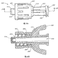
Figure 18 A is the perspective view of another embodiment of closeable male luer adapter.
Figure 18 B is the cross-sectional view of the adapter among Figure 18 A.
Figure 18 C is the details of the cross-sectional view of the adapter among Figure 18 A.
Figure 19 is the perspective view of the syringe adjacent positioned terminal with having joint luer of the adapter among Figure 18 A.
Figure 20 is that element among Figure 19 is at the perspective view of engagement state.
Figure 21 is the perspective view of another embodiment of the closeable male luer adapter that engages of the syringe terminal with having joint luer.
Figure 22 A is the cross-sectional view of another embodiment of closeable male luer adapter.
Figure 22 B is the details of the cross-sectional view of the adapter among Figure 22 A.
Figure 23 A is the side view of another embodiment with closeable male luer adapter of pipe box.
Figure 23 B is the cross-sectional view of the adapter among Figure 23 A.
Figure 23 C is the perspective view of an embodiment of the contiguous closed interface connector of closeable male luer adapter, in this stage, stops the fluid said interface connector of flowing through.
Figure 23 D is that element among Figure 23 C is at the perspective view of engagement state.
Figure 24 A is the perspective view of another embodiment of closeable male luer adapter.
Figure 24 B is the cross-sectional view of the adapter among Figure 18 A.
Figure 25 A is the side view of another embodiment with closeable male luer adapter of pipe box.
Figure 25 B is the cross-sectional view of the adapter among Figure 25 A.
Figure 26 A is the perspective view of another embodiment with closeable male luer adapter of the luer interface connector that flexibly connects.
Figure 26 B is the perspective view of another embodiment with closeable male luer adapter of the luer interface connector that flexibly connects.
Figure 27 is the perspective view of another embodiment of closeable male luer adapter.
Figure 28 is the cross-sectional view of the adapter among Figure 27.
Figure 29 is another cross-sectional view of the adapter among Figure 27.
Figure 30 is the cross-sectional view that the adapter syringe terminal with having joint luer among Figure 27 engages, in this stage, and the prevention fluid said luer joint connector of flowing through.
Figure 31 is adapter and syringe among Figure 30 and the cross-sectional view with pipe joint of luer interface coupling part, in this stage, allows the fluid said assembly of flowing through.
Figure 32 is another cross-sectional view of adapter, syringe and pipe among Figure 31, and in this stage, said joint is in the process of sealing.
Figure 33 is the perspective view that the adapter among Figure 27 engages at the embodiment with the fluid injection exhaust cap.
Figure 34 is the perspective view of another embodiment of closeable male luer adapter.
Figure 35 is the cross-sectional view of the adapter among Figure 34.
Figure 36 is the perspective view of another embodiment of closeable male luer adapter.
Figure 37 is the cross-sectional view of the adapter among Figure 36.
Figure 38 is the cross-sectional view of another embodiment of closeable male luer adapter.
Figure 39 is the cross-sectional view that the adapter syringe terminal with having joint luer among Figure 38 engages, in this stage, and the prevention fluid said luer joint connector of flowing through.
Figure 39 A is adapter and syringe among Figure 39 and the cross-sectional view with pipe joint of luer interface coupling part, in this stage, allows the fluid said assembly of flowing through.
Figure 40 is the cross-sectional view of another embodiment of closeable male luer adapter.
Figure 41 is the cross-sectional view of another embodiment of closeable male luer adapter.
The specific embodiment
The multiple device that has shown second end that is used to seal luer joint connector (male luerconnector) in one aspect of the invention.In certain embodiments, said closing means is used to prevent and/or stops fluid to flow out or flow into said luer joint from said luer joint, but when said luer joint engages by manual unlocking or with a corresponding luer interface permission fluid flow.Should be understood that the interference or the obstacle of fluid flow at the term of this used for example " sealing " or " sealing ".Should said term be interpreted as to require a kind of particular structural or structure said particular structural or be configured in all situations and be issued to fluid-tight completely.
Shown a embodiment among Figure 1A at the closeable male luer adapter 10 of detent position.Said luer adapter 10 is connected to and is filled with the transfusion bag that fluidic gravity supplies with (IV bag: or venous transfusion bag) 9 from shaft bar 11 suspension.The part of pipe 13 is connected the bottom of said bag 9.The other end of said pipe 13 is connected to first end 12 of luer adapter 10.As long as said luer adapter 10 remains on the closed construction state, the closing means on second end, 14 inside of luer adapter 10 just prevents to be contained in fluid in the sack 9 and flows through pipe 13 and spill from luer adapter 10.
Illustrate the said adapter 10 when open position among Figure 1B.Fluid can flow into first end 12 of adapter 10 and flow out from second end 14 of adapter 10.Through catch second end of said closeable male luer adapter 10 with two fingers; Catch pipe 13 and move said finger in the opposite direction a little with two other fingers, medical personnel can move to said structure with said luer joint connector 10.
Illustrated IV transfusion system can easily transport fluid in patient's body in Figure 1A and 1B.In most of the cases, said pipe 13 is full of air when it is connected to said transfusion bag 9 at first.If the other end of said pipe 13 is connected to the adapter of sealing, shown in Figure 1A, air can not be discharged and fluid can not get into pipe 13 from transfusion bag 9.Therefore, said luer adapter 10 manually moved to reach the position of opening and all discharge said adapter 10, and the fluid in the transfusion bag 9 is full of pipe 13 and adapter 10 up to all air.Said process is known as " fluid injection aerofluxus (priming) ".In case said fluid circuit and adapter are by suitably fluid injection aerofluxus; Said medical personnel just can discharge the opposite force on second end 14 that is applied to said luer adapter 10 and the said pipe 13 rapidly, and the closing means of said luer adapter 10 can stop the fluid luer adapter 10 of flowing through rapidly.
Referring now to Fig. 1 C, conduit 17 is inserted patient's arm 15.Said conduit 17 thrusts the skin of arm 15 and preferably is connected with patient's blood flow fluid.Said conduit 17 also is connected to the medical pipe 19 that is connected with interface medical connector 21.The example of illustrated interface medical connector 21 is ICU Medical in Fig. 1 C; Inc.; San Clemente, a kind of form of Clave
 adapter that California makes.In United States Patent (USP) NO.5685866, illustrate and described the various embodiment of the adapter of said type, this patent is incorporated at this by reference in full.It is contemplated that the embodiment of a lot of luer joints disclosed here can use with the interface connector of other type.Use standardization program in advance said pipe 19, conduit 17 and interface connector 21 to be injected fluids.That kind just as described earlier, said luer joint connector 10 engages by the fluid injection aerofluxus and with said interface connector 21.That kind just as will be described in further detail below when said luer adapter 10 engages with said interface connector 21, allows fluid to flow into the patient from said transfusion bag 9.When said joint connector 10 was opened with said interface connector in 21 minutes, stop fluid to flow out once more from second end 14 of said joint connector 10.Usually, also stop fluid to flow out from the opening in the said interface connector 21.
Illustrated embodiment among Figure 1A to 1C is below described in further detail.Each other embodiment disclosed here can be used in illustrated fluid system and various variant and the alternative form.In addition, it is contemplated that, can be used in various types of other medical fluid systems according to the various embodiment of adapter of the present invention.For example, the adapter that is disclosed also can be used for carrying body fluid or insulin, the nutritional solution of for example blood, urine and/or the fluidic treatment fluid that uses of chemotherapy for example.The adapter that is disclosed also can be used to make various other element interconnections of transfusion system.
Illustrate the closeable male luer adapter among Figure 1A to 1C in more detail referring now to Fig. 2 to 9.As illustrated in Fig. 2, the luer adapter 10 of said assembling comprises four parts: shell 23, valve member 16, resilience parts 18 and sealing ring 20 (in Fig. 2, not illustrating).These parts are shown among Fig. 3 to Fig. 6 respectively, and will discuss in further detail with reference to said accompanying drawing.Said luer adapter 10 can be by more or less section construction, and said part can be combined into different structure.
Fig. 3 illustrates the shell 23 with the isolating adapter 10 of other part of said luer joint connector 10.Said shell 23 is generally the tubular structure with axial passage 28, and said axial passage 28 extends through second end 14 of terminal (the luer tip) 22 of shell 34 and mid portion 32 and luer to said shell 23 from first end 12 of adapter 10.In certain embodiments, said shell 23 approximately is 9/8 inch from the length of first end 12 to luer terminal 22.Preferably, but dispensable, thus said shell 23 is less than or equal to about 3/2 inch weight and volume that minimizes adapter from the length of first end, 12 to second ends 14.For special applications, said shell 23 also can have any suitable length.Said luer terminal 22 is connected to the remainder of said shell 23 at base portion 25, said base portion 25 by pipe box 24 (shroud) around.Extend beyond edge 29 some distances of said pipe box towards the end 27 of the said luer terminal 22 of second end of said luer adapter 10.
Thereby said pipe box 24 preferably has female thread 26 on inwall helps with a kind of dismountable mode adapter 10 to be connected to other medical apparatus and instruments securely.In other embodiments, said pipe box 24 can comprise being used to provide and comprises for example other structure or the material of the releasable connection of quick release mechanism and other device.Said pipe box 24 comprises a plurality of depressions on its outer surface so that help the user to catch and reverse the pipe box 24 of said shell 23 securely with finger.Thereby said depression 31 has the sidewall 33 that upwards phases down prevents that adapter 10 is from the finger slippage.Each depression 31 on the end of first end of said adapter 10; The surface of said shell 23 substantially with the surface co-planar of said depression 31; But each depression 31 on the end of second end 14 of said adapter 10; The surface of said depression 31 is left on the surface of said shell 23, and preferably is higher than the surface of said depression 31.Said structure allows finger on the direction of second end 14 of said adapter 10, cosily sliding into the position that is used to hold tight in one's hands or reverse said adapter 10 along shell 23.In case finger is in the position that needs, stop finger on the direction of second end 14, to be moved further in the tapered wall 33 on an end of second end 14 of said adapter 10 of depression 31.A series of depressions 31 are extended around the whole outer surface of said pipe box substantially, thereby no matter in use the orientation of adapter 10 how, user's finger runs into a depression 31 probably when being placed on the opposite side of said adapter 10.
In illustrated embodiment, terminal 22 have the outer wall of taper.Said terminal 22 diameter diminishes towards second end 27 from base portion 25 gradually.Said terminal 22 are included in the hole on its second end 27.On the base portion 25 of luer terminal 22, internal holes 35 (see figure 8)s are communicated with the zone of the fluid passage 28 in the mid portion 32 of said luer adapter 10.Can abide by the for example application standard or the terminal size of the said luer of rule manufacturing of the standard of ANSI.
The inwall of said luer terminal 22 preferably includes shelf (shelf) 30; Said shelf 30 radially inwardly towards by said luer terminal 22 around the axis of fluid passage 28 extend, thereby make fluid passage 28 narrower in said terminal 22 second end 27 becomes the zone of neighbour nearly said second end 27.In illustrated embodiment, radially inwardly towards the surface of the shelf 29 of the central axis of said adapter 10 with the mode similar narrow down gradually (seeing Fig. 8 and 9) with the taper of said terminal 22 outer surface.In said structure, the internal diameter of said shelf 29 narrows down to the lateral direction towards second end in the side towards first end from said shelf.As following will describe in further detail, when second end of valve member 16 time near it, the shelf 29 in said luer terminal 22 helps to hinder and/or the prevention fluid is flowed through said adapter 10.
The mid portion 32 of shell 23 is between pipe box 24 and last shell 34.Like diagram, said mid portion 32 has than pipe box 24 or goes up the little external diameter of shell 34.Said mid portion 32 also has two the orthogonal substantially openings 36 respect to one another on the opposite side that is arranged on said shell 23.When the said adapter 10 of assembling, said mid portion 32 is covered (seeing, for example Fig. 2) by resilience parts 18 substantially.Therefore, in use, said mid portion 32 does not contact with finger usually.Thus, in certain embodiments, but said mid portion 32 needn't use grip surface.Therefore, said mid portion 32 can have littler diameter and more slick surface than any one other part of shell 23.
The said shell 34 of going up is divided into two wall part 45a, 45b by two slits 38 (only visible in Fig. 3) substantially.The said shell 34 of going up is included in a series of depressions 37 similar with the depression on said pipe box 24 on shape and the function.The said shell 34 of going up also can comprise and extends to one or more protruding 43 in the said slit 38.In the structure of said assembling, said protruding 43 help a part with resilience parts 18 to remain on (see figure 2) between the slit 38 of said wall part 45a, 45b.In certain embodiments; Said protruding 43 from its towards the less thickness of the end of first end of said adapter to tilting at its big thickness towards the end of second end of said adapter; The inclination of said convexity helps desired position and direction are inserted and remained on to the said part of said resilience parts 18, in use allows said resilience parts 18 crooked and distortions simultaneously.When adapter 10 was moved to open position, it was too far away also to help to prevent that towards a group protruding 44, said protruding 43 of second end of said valve member 16 said valve member 16 from advancing through contact.During said protruding 43 inclination allowed in being assembled into shell 23, the convexity 44 of said valve member 16 was advanced towards second end, and passed through the convexity 43 of shell 23.On each wall part towards the angle 47 preferably rounded (rounded) of first end of adapter so that prevent in use colluding extensions, swipe or other damage or stimulation to finger or resilience parts 18.
As shown in Figure 3, the said outer surface of going up shell 34 comprises lower shelf 39, and the outer surface of pipe box 24 comprises shelf 41, and in the structure (see figure 2) of assembling, said shelf 41 is configured to help to keep around shell 23 core of resilience parts 18.The said shelf 39 of going up shell 34 preferably substantially level so that hinder any slip of said resilience parts 18 on the direction of first end of adapter.The shelf 41 of said pipe box 24 preferably is tapered (see figure 8) so that during the manufacturing of adapter 10 said resilience parts 18 suitably are being positioned on the shell 23.
Said shell 23 can be by any structure of multiple different materials.In certain embodiments, said shell 23 can be by the material structure of the relative stiffness of for example Merlon or other polymeric material.The shell 23 of said embodiment and/or valve member 16, or the element of other embodiment also can be made up of the hydrophobic material of for example BAYER Makrolon or any other suitable material.
Referring now to Fig. 4 A, illustrate valve member 16 with the isolating said luer adapter 10 of other element of said adapter 10.In certain embodiments, said valve member 16 comprises the fluid passage 52 of a vary in diameter, and said fluid passage 52 extends to second end 56 of said valve member 16 from first end 48 of said valve member 16, said fluid passage 52 by other structure ring around.Near said first end 48, the appropriate section of said valve member 16 and said fluid passage 52 is wide relatively so that hold the part of the medical pipe of insertion normal diameter wherein.Near the centre of said valve member 16, be connected to part near first end of said valve member 16 around the pipe 40 of the part of said fluid passage 52.Said pipe is along contiguous two the parallel substantially pillars of at least a portion (strut) 42 of said pipe 40.Said pipe 40 can have circular cross section or other suitable cross section.The preferably relatively thin and flat of said pillar 42.First end of each pillar 42 is connected with valve member 16 at the mid portion substantially of said valve member 16, and second end of each pillar extends second end 56 towards said valve member 16.Second end 56 of said valve member 16 preferably extends fartherly than the said end of said pillar.Preferably, between the outer wall of the inwall of each pillar 42 and said pipe 40, there is the space.
To first end 48 of valve member 16, comprise having protruding 44 broader zone from the centre of valve member 16 along the said fluid passage 52 of outer surface of said fluid passage 52.Protruding 44 form two grooves 46 (in Fig. 4 A, only demonstrating), and said two grooves 46 are along the opposite side longitudinal extension of said valve member 16 main bodys.In certain embodiments, illustrated like accompanying drawing, said pillar 42 and said groove 46 separate along circumference.
Near said valve member 16 and pipe 40, circumferential groove 48 can form around the periphery of said valve member 16 main bodys.Protruding protuberance 49 can form along the edge towards the groove 48 of first end of said adapter, and the mid portion of the convexity of said valve member 16 can form the edge towards the said groove 48 of second end of said adapter simultaneously.In certain embodiments, the protuberance 49 of said convexity is not that the periphery that centers on first end of said valve member 16 equably extends, but opposite, the protuberance 49 of said convexity has two major parts of each interval on diameter.
The depression that can form through the skin in said part reduces the said valve member 16 necessary quantity of material of structure.Said pipe 40 can have the passage 50 that is provided with through wherein.Said passage 50 preferably extends to from the hole 52 on first end of said valve member 16 and is arranged in the pair of holes 50 of second end of contiguous said valve member 16 (at the only visible one of which of Fig. 4 A) substantially.In illustrated embodiment, said hole 52 is being a rectangle usually in shape.Only also can be formed with a hole and more than two holes near the zone of the said pipe 40 of second end of said adapter, and also can adopt other shape with a plurality of holes.For example, said hole 52 can form shape with teardrop (for example, at one end narrow and at relative other end broad), and said shape helps the injection-molded manufacture process.In addition; In certain embodiments, said valve member 16 can be configured to not have the fluid passage and as stoping fluid around said valve member 16 mobile retardance pistons (blockingspunger: or be called block plunger) rather than be used for the device of conveyance fluid between first and second ends of said adapter 10.
The pipe 40 of said valve member 16 comprises flange portion 58 at its second end.Said flange portion 58 preferably extends farther than the neighbouring part of said pipe 40 diametrically.In certain embodiments, said flange portion 58 can by identical with the remainder of said pipe 40 and substantially identical materials form.Said flange portion 58 preferably is tapered towards second end of said pipe 40 from first end of said valve member 16.In certain embodiments, said cone shape becomes the angle of 5 degree and has substantially the identical taper of taper with the radially inner lining face of the shelf 30 of said shell 23.Also can use the taper of other gradient, perhaps not use taper.
As the shell among Fig. 3 23, said valve member 16 can be by a lot of different materials structures.The example of said material comprises Merlon or other polymeric material.Said valve member 16 can be identical with said shell 23 length substantially or short a little.For example, the length of said valve member 16 is approximately 1 inch.In certain embodiments, said valve member 16 can be shorter than the length of said shell 23 substantially.Said valve member 16 can be formed by the rigid material identical with said shell.In special applications, for example, require semi-rigid material or flexible material are used for said valve member 16, more particularly, require semi-rigid material or flexible material are used for the flange portion 58 towards second end of said pipe 40.
Make said valve member 16 through injection-molded.In certain embodiments, at least two cast gates are used for being convenient to the plastics in the whole said fusing that distributes in molded.Preferably; Cast gate can be positioned at along a side of said valve member 16 between the protuberance 49 of the end of the said pillar 42 of first end of said adapter and said convexity, and another cast gate can preferably be arranged near the hole 52 on the said valve member 16.Yet the position of said cast gate is not fixed, when the said valve member 16 of injection-molded, can use said cast gate in other position of valve member 16.The shell 23 of and other embodiment said with same material structure and valve member 16 have reduced the chance of said adapter 10 mis-behaves that the chemical interaction owing to thermal expansion/thermal contraction or said adapter 10 environment of living in it causes.
Although shown the valve member 16 of illustrated embodiment among Fig. 4 A, also can use many other structures.In certain embodiments, said valve member 16 can be smooth relatively on its outer surface, and can comprise the pipe 40 that limits passage 50 substantially.In another other embodiment, can be along the pillar 42 of the side arrangement varying number of said valve member 16.
Visible among the illustrated embodiment from Fig. 4 B; Protuberance 150 near the convexity of first end of said valve member 16 also can be the outer engagement surface 150 of for example screw thread, so that for example the medical apparatus and instruments (not shown) of syringe is connected to first end of said valve member 16 removedly.
Among the illustrated embodiment, said passage 48 can be tapered along said inner surface again in Fig. 4 C.The taper of said passage 48 (or being tapered) can cause said width of channel to reduce, and promptly said passage has large-size and has reduced size towards second end 184 of said valve member 16 on first end 180 of said valve member 16.The inner conical of said passage 48 is can be with the taper of luer joint complementary and closely cooperate.Said inner conical can meet the standard and/or the rule of ANSI, the for example standard of medical syringe.In illustrated embodiment, the pipe 40 of said valve member 16 does not have the flange portion 58 that in the embodiment of Fig. 4 A, shows, extend radially outwardly the wall that surpasses said pipe 40.On the contrary, the wall of said pipe 40 radially inwardly diminishes in the zone of second end gradually.The second portion 170 that the second end 27a of the terminal 22a of said luer can have small cross section, second portion 170 have reduced the probability that fluid spills along the inner surface of the second end 27a of the terminal 22a of said luer.Near the second end 27a of the terminal 22a of said luer; Use multitude of different ways; Big transverse cross-sectional area 160 can carry out the transition to smaller cross-sectional area zone 170 towards second end of said adapter; For example use like illustrated step-wise transition among Fig. 4 C (stair-step transition) or a kind of progressive tapering transition, or other transition.The cross-sectional diameter of some examples of the opening on the second end 27a of the terminal 22a of said luer comprises about 2mm or less than the diameter of 2mm, comprises the diameter of about 0.5mm, 0.75mm, 1.0mm, 1.25mm, 1.5mm, 1.75mm.The diameter of the opening on the second end 27a also can be in the scope of 0.4mm-1.8mm, 0.5mm-1.5mm, 0.5mm-1.0mm.Also can use within the cited scope or outside other diameter.In addition, the size of second end that can suitably select said valve member 16 is so that occupy the space in the opening on the second end 27a of the terminal 22a of said luer.
Shown in Fig. 4 B and 4C, said closeable male luer adapter 10 has interface end 180 and luer tip side 184.Closed interface connector 210 (back is with more detailed description) among closed interface connector 21 among Fig. 1 C (with reference to top) and Figure 10 to 11; And the interface connector with other standard of similar external structure, also have interface end and tip side.In a lot of embodiment, said interface connector utilizes sealing member or other fluid obstacle to stop fluid flow in interface end rather than at tip side.In a lot of embodiment of this illustrated closeable male luer adapter, there are not the sealing member or other fluid obstacle that are presented on the said interface end.Yet the interface end of any closeable male luer adapter disclosed here can be configured to comprise closed interface end.For example, have interface connector 21 210 or the structure that is used for the selectivity fluid impedance of the interface connector of any one other standard can be contained in the interface end of any closeable male luer adapter disclosed here so that a kind of selectivity sealing or stop the adapter of fluid flow at two ends is provided.As shown in the United States Patent(USP) No. 5685866, in some embodiment of the said type with closed interface end and tip side, can help being placed on the said interface opening elastic sealing element or near said interface opening.Through said seal member is placed with said method, can before using antibacterial, utilize wiping action to clean said interface opening so that prevent that chip, antibacterial, antibacterial or other harmful substance from accumulating on the said seal member nocuously and/or in the zone between seal member and the connector shell that is close to said seal member.
With reference to Fig. 5 resilience parts 18 are discussed in further detail below.In illustrated embodiment, said resilience parts 18 are formed by two rings 60,62 being opened in 64 minutes by two elastomeric elements.Said ring 60,62 and/or said elastomeric element 64 can be made up of deformable material, and said deformable material is configured to when it stretches, apply restoring force.Thus, if draw said ring 60,62 with opposite direction, said elastomeric element 64 is used for ring 60,62 is returned to the structure that they do not have stretching, extension.
Said elastomeric element 64 can be made up of a variety of elastomeric materials.In certain embodiments, said elastomeric element 64 can be made up of the silicone rubber elastomeric material.In further embodiments, said elastomeric element 64 can be made up of shaping material (shape-memory material).In more another embodiment, said elastomeric element 64 and/or said resilience parts 18 can comprise that spring or other can apply the structure of restoring force.
Said ring 60,62 also can be made up of multiple material.In certain embodiments, said ring 60,62 by with form elastomeric element 64 identical deformably resilient materials and constitute.Thus, can ring 60,62 be stretched over the diameter that extends around the suitable part of shell 23, each independently encircles 60,62 and is connected on the suitable part of said shell 23.The restoring force of said ring 60,62 can be used for effectively each ring 60,62 being remained on the appropriate location of shell 23.In further embodiments, said ring 60,62 can be made up of rigidity or semi-rigid material, and can for example comprise the semicircle spare (half-circles) that can snap in said position and come out from said position.In certain embodiments, said resilience parts 18 can be combined into one with said valve member 16 or shell 23.In certain embodiments, can use other structure and/or structure, be used for optionally said valve member 16 being advanced with shell together with the mode that is different from resilience parts 18.
With reference to Fig. 6 said hermetic unit 20 is described in further detail below.In certain embodiments, said hermetic unit 20 is cylindrical substantially and have a hole of passing wherein 66.In certain embodiments, said hermetic unit 20 further comprises a pair of rectangular preiection substantially 68, and said rectangular preiection 68 sidewall from said cylindrical part on position relative on the diameter extends.Said protruding 68 can have different shapes and/or position.Said hermetic unit 20 also can have the mid portion 67 of substantially littler diameter, and two rings 69 with bigger diameters are looped around the two ends of said mid portion 67.
Said hermetic unit 20 can be made up of a lot of different materials.In certain embodiments, said hermetic unit 20 is made up of silica-based deformable material 70.Silica-based deformable material is the material that forms the fluid-tight sealing with plastics and other rigid polymeric material.Said hermetic unit 20 can be by forming with said resilience parts 18 identical materials.
In Fig. 7, shown some element of said luer joint connector 10 embodiment.As shown in the figure, omitted shell 23.On their other assembling positions of branch, valve member 16, resilience parts 18 and hermetic unit 20 have been shown.
The specific phase that to discuss in further detail below between the each several part of said luer joint connector 10 connects.As shown in the figure, the less ring 62 of said resilience parts 18 is engaged in the circumferential channels 54 of said valve member 16.In certain embodiments, can less ring 62 stretching, extensions be had bigger internal diameter up to the protuberance 49 than the convexity on first end at said valve member 16.As shown in the figure, in case said little ring 62 arrives when centering on the position of said circular channel 54, can it be discharged, thereby little ring 62 is tightly around said circular channel 54.
In Fig. 7, said hermetic unit 20 parts are hidden by resilience parts 18, and preferably, said hermetic unit 20 closely cooperates and between the pillar 42 of said valve member 16 around pipe 40.
Fig. 8 illustrates the cross section of said luer joint connector 10 of the current embodiment of contiguous exemplary interface adapter 92.In said cross-sectional view, can see interconnecting and interacting between said shell 23, valve member 16 and the hermetic unit 20 in more detail.Said valve member 16 is configured to be placed in the shell 23.As scheme illustratedly, the pipe 40 of said valve member 16 can insert and through chamber 28.Simultaneously, said pillar 42 is configured to pass corresponding groove, and said groove longitudinal extension is through the mid portion 32 of said shell 23.In the structure of assembling, said pillar 42 is adjacent end 22 along both sides, and said pipe 40 is at least partially housed in terminal 22.In said protruding 44 slits 38 that are maintained in the last shell 34 that is formed on said shell 23.
Closing means 56 is suitable for preferably whenever not engaging with interface connector 92 at luer joint connector 10, and the fluid passage sealing is communicated with the external environment condition fluid, and said fluid passage extends through closeable male luer adapter 10.In illustrated embodiment, fluid passage 52 comprises the passage 54 of chamber 28 and valve member 16.The closing means 56 of illustrated embodiment comprises the inner conical of the projection 29 in pipe 40 flange portion 58 and chamber 28.When these two whens contact surface, they can form sealing near second end, 20 places of luer joint connector 10 or its.
The inner conical surface of the projection 29 in the inner conical surface of the projection 58 of the pipe 40 of coupling and chamber 28 helps to realize the sealing of interface connector 92 substantially.Preferably, form the sealing of relative fluid-tight.Joint between the projection 29 and 58 is much alternate manner realizations also.In certain embodiments, the material of the projection 29 in the material of flange portion 58 and chamber 28 is configured to closely be combined together, and by forming by fully compatible material, so that form the sealing of fluid-tight.In other embodiments, the other part of flange portion 58 and/or valve member 16 can be made up of deformable material, and this deformable material is the profile of the inner surface of mating cavity 28 more closely, and chamber 28 needn't have tapering.Hermetic unit 20 is configured to anti-fluid in certain embodiments and from luer joint connector 10, leaks.When valve member 16 splice enclosure 23, hermetic unit 20 is between the mid portion 32 and pipe 40 of shell 23.When flowing along pipe 40 outer surface in the chamber 28 of fluid at shell 23, hermetic unit 20 and more specifically, the ring 69 anti-fluid at arbitrary end place of hermetic unit 20 flow through mid portion 32.
Further describe the structure of exemplary interface adapter 92 below with reference to the embodiment shown in Fig. 8.Interface connector 92 can comprise elongate body 72, and this main body 72 has the fluid passage 74 of passing it, and interface connector 92 can have terminal 76 near its far-end.In certain embodiments, the end 76 of interface connector 92 has the layout surface 78 of radially extending on its outer surface.Interface connector 92 can have the fluid conduit systems that is positioned at interface connector 92.Not that total interface adapter with adapter disclosed here 10 couplings all comprises and maybe needs this fluid conduit systems.Along the interior abutment surface 80 of interface connector 92, fluid passage 74 preferably tilts to make the diameter of fluid passage 74 on the direction of far-end, reducing.
As shown in Figure 8, shell 23, valve member 16, resilience parts 18 and hermetic unit 20 are in the structure of assembling, and wherein the sealing that is formed between the inside in flange portion 58 and chamber 28 of closing means 56 engages.In addition, hermetic unit 20 sealings are bonded between valve member 16 and the shell 23.Can flow through the window 54 of the pipe 40 of valve member 16 from the fluid of passage 50.In this position, the internal communication of window 54 and end 22, but still be not communicated with external environment condition.Chamber 28 is closed at its second end by closing means 56, is closed at its first end by hermetic unit 20.
As shown in Figure 8, the pillar 42 of valve member 16 extends through the slit in shell 23, makes their end extend near the position the end of pipe box 24 towards second end of adapter.These pillars 42 are configured to advance and the near-end 84 of joint interface connector 92 when engaging with closeable male luer adapter 10 when interface connector 92.
In Fig. 8, luer joint connector and luer interface connector are shown as the structure that does not have joint.For luer joint connector 10 is engaged with interface connector 92, the radially extensional surface 78 of interface connector 92 is screwed in the female thread 26 of luer joint connector 10.
As shown in Figure 9, these two luer joint connectors toward each other threads engage be positioned adjacently at the conical outer surface place of terminal 22 correspondence up to the taper of the inner surface of interface connector 92.In other embodiments, two luer joint connectors can threads engage form sealing up to second end of end 22 with the corresponding surperficial (not shown) of interface connector 92.
Along with luer joint connector 10 and interface connector 92 move towards each other and threads engage, the pillar 42 of the end contact valve member 16 of interface connector 92.When luer joint connector 10 and interface connector 92 are moved further and during threads engage, thereby pillar 42 valve members 16 are moved on the direction of first end of joint connector by interface connector 92, and this makes valve member 16 with respect to shell 23 displacements.Thus, flange portion 58 moves towards first end of joint connector from second end of the end 22 of shell 23.When these two conical surfaces separate, between valve member 16 and shell 23, form the space, and fluid is allowed to get in the fluid passage 74 of interface connectors 92 through hole 30, or vice versa.When some embodiment with interface connector 92 use, at the housing contacts pillar 42 of interface connector 92 so that before opening joint connector 10, second end of internal flow conduit contact valve member 16.In certain embodiments, sealing remains intact inner surface 80 up to the end of interface connector 92 and forms with the tight of outer surface of the end 22 of luer joint connector 10 and contact.Thus, the passage 50 of luer joint connector 10 needn't be communicated with the external environment condition fluid.
When valve member 16 moved with respect to shell 23, the elastomeric element 64 (in Fig. 9, not illustrating) of resilience parts 18 was expanded and is applied restoring force.As long as interface connector 92 engages luer joint connector 10, this restoring force just can be by the surface of radially extending 78 opposings of the interface connector 92 of the female thread 26 of contact shell 23.Yet, when interface connector 92 when luer joint connector 10 is return, resilience parts 18 turn back to the fluid-tight engagement state with chamber 28 with the valve element of valve member 16.
Although relatively move between shell 23 and the valve member 16, hermetic unit 20 is preferably managed the fluid obstacle between the inner surface in 40 outer surface and chamber 28.In certain embodiments, the position of hermetic unit 20 keeps by protruding 68.In other embodiments, hermetic unit 20 can be glued to through the outer surface with deformable material 70 on the inner surface in chamber 28 of shell 23 and locate.Also can use other means of fixing seal part 20.
As shown in Figure 9, in the structure of opening, the fluid passage 74 of interface connector 92 can be communicated with passage 50 fluids of valve member 16.Thereby fluid can flow into from the pipe 13 that is connected to luer joint connector 10 in the passage 50 of valve member 16; Through window 54 entering chambeies 28; The fluid passage 74 that enters into interface connector 92 28 is flowed out from the chamber in hole 30 through 22 the second end place endways, and vice versa.Hermetic unit 20 anti-fluid are leaked from luer joint connector 10 through the gap between shell 23 and the valve member 16.Fluid-tight sealing also can be formed between the taper of inner surface 80 of taper and interface connector 92 of correspondence of end 22 of shell 23.
With reference to Figure 10, adapter 10 is shown as contiguous closed luer interface connector 210.In this illustrated example embodiment, closed luer interface connector 210 comprises shell 213, void space 212, fluid passage 218, has the fluid conduit systems 216 in one or more holes 215, the compressible seal element 214 with proximal surface 217 and threaded bonding land 211.Closed interface connector 210 is positioned to second end 56 of its contiguous luer joint connector 10 of near-end.The threaded bonding land 211 of closed interface connector 210 can be consistent with the normal size of luer adapter, for example satisfies the standard of American National Standards Institute.Compressible seal element 214 can be made up of the waterproof resilient material, and said resilient material size when applying power can reduce.Fluid conduit systems 216 can by rigid material for example polycarbonate plastic form, when on closed luer interface connector 210, applying the power that is enough to compression seal element 214, said rigid material can resistance to deformation.Fluid passage 218 can be communicated with fluid conduit systems 216 with second end, 219 fluids of luer interface connector 210.At least one hole 215 in the fluid conduit systems 216 can be by compressible seal element 214 sealings in case void space 212 fluids between the inwall of fluid passage 218 and compressible element 214 and shell 213 are communicated with and/or with the internal fluid communication of shell 213.The size in said one or more hole 215 can suitably be small enough to allow fluid to pass through between fluid passage 218 and the void space 212 with suitable flow velocity.It is about 1mm that said one or more hole 215 is of a size of diameter, although also can use irregularly shaped and other size.Also can use diameter is 1mm or about 1mm to 3mm at least, or less than the about hole of the size of 1mm.Adapter 10 can with contain fluidic pipe 13 and engage.
With reference to Figure 11, adapter 10 can with closed interface connector 210 threads engage.As directed, the threaded district 211 of closed interface connector 210 can engage with joining connector 10,210 with the female thread 26 of luer joint connector 10.In illustrated joint, luer terminal 22 enters in the closed interface connector 210 through compression compressible element 214.Shown in figure, luer terminal 22 is contact compressible element 214 on the proximal surface 217 of compressible element 214.The power that is used for joining connector 10,210 and splicing tpae threaded area 26,211 is enough to compression seal element 214 to expose the hole 215 in fluid conduit systems 216.When potted component 214 was compressed, fluid passage 218 was communicated with the inner space fluid of luer terminal 22.
When but luer terminal 22 further entered in the closed interface adapter 210, fluid conduit systems 216 contacts were towards the end of the valve member 16 of second end of joint connector.Through contacting and advance continuously luer end 22, valve member 16 is towards first end displacement of joint connector.Resilience parts 18 are applying seal force to valve member 16 on the direction of second end of joint connector.As a result, the interface towards the valve member 16 of second end of joint connector keeps in touch with fluid conduit systems 216 in engaging process usually.When valve member when on the direction of first end of joint connector, moving, the flange portion 58 of valve member 16 separates with the inner surface of shell 23, said inner surface is passed through in hole 30.As a result, window 54 is opened and is communicated with closed interface connector 210 fluids.Compressible potted component 214 forbids that fluid surpasses the inside that luer terminal 22 flow into closed interface connector 210.In this structure; Fluid can be from flowing and flow in the pipe 40 towards second end of joint connector at the pipe 13 of the end of valve member 16; Enter into the inside in chamber 28 through window 54; Flow out into the inside of the shell 213 of closed interface connector 210 from 1uer terminal 22 interior holes, the hole 215 of incoming fluid conduit 216 also flows into the fluid passage 218 in fluid conduit systems 216 inside.Thus, second end of adapter 210 is communicated with near-end 219 fluids of closed interface connector 210.In addition, hermetic unit 20 is preferably managed the fluid obstacle between the inner surface in 40 outer surface and chamber 28, and limit fluid flows towards closed interface connector 210.When valve member towards the surface of second end of adapter and interface connector parts for example fluid conduit systems 216, when pillar 42 directly contacts, pillar 42 engages with interface connector.
Adapter 10,210 can threads engage.Between joint aging time; So that the flange portion 58 towards the end of second end of joint connector of valve member 16 engages with the inner surface of luer terminal 22, the power that is applied by resilience parts 18 can turn back to its preparatory engagement state with adapter 10 through pilot valve parts 16.Equally, the elastomeric material of forming compressible seal can turn back to its shape at detent position, and proximal surface 217 can seal the nearly interface of closed interface connector 210.
Referring now to Figure 12, adapter 10 can engage with syringe 250.In Figure 12, syringe 250 is shown as located adjacent one another with adapter 10.Syringe can comprise joint connector 252, piston 258, container 260 and point fixture 262 easily.Luer adapter 252 may further include tapped pipe box 254 and syringe luer terminal 256.In the embodiment of illustrated adapter 10, threaded surperficial 150 are arranged on the outer surface of first end of valve member 16.
Referring now to Figure 13, adapter 10 can with syringe 250 threads engage.Pipe box 254 can with valve member 16 towards the engaged at end of first end of adapter so that adapter 10 is connected to syringe 250.The container 260 of syringe 250 can be communicated with pipe 40 fluids in valve member 16 inside.
Referring now to Figure 14, shown the viewgraph of cross-section of the joint among Figure 13 among the figure.Syringe 250 through between the threaded surface 150 of pipe box 254 and valve member 16 engage and with adapter 10 threads engage.The luer of syringe 250 terminal 252 extends in the pipe 40 of valve member 16.The internal fluid communication of the container 260 of syringe (be shown as container 260 in have fluid at this) and valve member 16.Fluid can flow through pipe 40 and flow towards the luer terminal 22 of adapter 10.In illustrated embodiment, fluid can not be discharged the joint luer end 22 of adapter 10, because flange portion 58 contacts with the inner surface in chamber 28.Therefore, in the hole 30 in second end of adapter terminal of shell 23 by valve member 16 obstructions.For syringe 250 with adapter 10 from the state transformation shown in Figure 12 to the state shown in Figure 14, valve member 16 possibly opened to discharge air (as described in detail later) temporarily.
With reference to Figure 15, adapter 10 is shown as contiguous syringe 250 and the hypodermic needle 270 with sheath, and at syringe 250 with have between the hypodermic needle of sheath 270.Syringe 250, the same with among Figure 12 can comprise luer joint connector 252, piston 258, container 260 and point fixture 262 easily.Luer joint connector 252 may further include tapped pipe box 254 and syringe luer terminal 256.Pin with sheath 270 can comprise shell 266 and pin 268, and said shell 266 has the protuberance 264 of protrusion at abutting end.
With reference to Figure 16, adapter 10 is shown as with syringe 250 and has the pin threads engage of sheath 270.The threaded surface of the valve member 16 of adapter 10 can engage with the threaded sleeve pipe 254 of syringe 250.Therefore, luer terminal 256 can protrude in the pipe 40 of valve member 16.Similarly, the protuberance 264 of protrusion can engage with the female thread 26 of the sleeve pipe 24 of adapter 10.The luer of adapter 10 terminal 22 can protrude in the shell 266 of stylophore.
In Figure 17, the index map shown in Figure 16 is shown viewgraph of cross-section.Adapter 10 is engaged by syringe 250 and the pin with sheath 270.Threaded surperficial 150 threads engage of the valve member 16 of syringe 250 and adapter 10.Female thread 26 threads engage with pin and pipe box 24 of sheath 270.
The luer of syringe 250 terminal 256 protrudes in the pipe 40 of valve member 16.The container 260 of syringe 250 is communicated with pipe 40 fluids of valve member 16 through luer terminal 256.
Adapter 10 engages with the pin with sheath 270.Shell 266 with pin of sheath 270 has the protuberance 264 of protrusion at its near-end.The protuberance 264 of protrusion and female thread 26 threads engage of the pipe box 24 of adapter 10.When luer terminal 22 entered in the shell 266 of pin 268, the near-end of shell 266 can contact the pillar 42 of valve member 16.When the pin with sheath 270 engages with adapter 10 fully, valve member 16 distance that has been shifted, this makes flange portion 58 fully separate with the conical inboard wall in chamber 28, flows out the window 54 of valve member 16 to allow fluid.Fluid can flow out the hole 30 in the end of luer terminal 22 then and get in the shell 266 of the pin with sheath 270.The pin 268 of hollow allows fluid from the shell 266 interior far-ends that flow out pin 268.Hermetic unit 20 is preferably managed the fluid obstacle between the inner surface in 40 outer surface and chamber 28, is limited to the fluid of intracavity and the flow direction in the hole 30 in luer terminal 22.Thus, in this stage, syringe 250 is communicated with the far-end fluid of pin 268.As before illustrated in Figure 13 and 14, in certain embodiments, do not having under element and the situation that second end 14 of adapter 10 engages, adapter 10 generally can not allow fluid to flow out syringe 250.Illustrated element is the pin with sheath 270 in Figure 15-17, yet for example also can using, those allow fluid flow and have other element that the luer extreme joints is divided.
Figure 18 A has shown the perspective view of another embodiment of closeable male luer adapter.Rotary connector 300 is made up of shell 310, inner passage 322 and potted component 330.Shell is further terminal 312 by luer, form at luer container 316, bonding part 318, actuating element 320 and the projection 340 of first end of adapter 300.Potted component 330 can have opening 350 in a lateral direction along its surface 314.Inner passage 322 can extend to luer terminal 312 from luer container 316.Shell 310 can be made up of the waterproof material of for example polycarbonate plastic.Other that is suitable for constructing shell 310 is exemplified as glass-filled GE polybutylene terephthalate (PBT) (glassed-filled GE Valox) 420 or polypropylene.Based on application, also can use a lot of other materials.
With before any other element engages, potted component 330 also can be provided with opening 350 in the surface 314 of second end of adapter.Opening 350 can be the slit in a lateral direction at the longitudinal axis of shell 310.Opening 350 can be in placed in the middle and other position that is positioned on the surface 314 on the surface 314.Potted component 330 can cover whole second end of luer terminal 312, or only is its part.In other method of attachment, potted component 330 can be connected on the shell through clad forming process.In this clad forming process; In first step; Shell 310 can form through injection-molded, then, and in second step; Shell 310 can be inserted into (or remaining in the mould) in the mould and suitably core rod (molding pin) (not shown) of size can be inserted through the wideer end of shell 310, for example second end.Silicone material can be injected in the mould to form potted component 330 then.In other embodiments, potted component 330 can be by gluing or adhere in the shell 310.
See that like illustrated embodiment in Figure 18 A as luer terminal 312 during not with another member engages, potted component 330 can forbid that fluid flows through shell 310.Thus, when having that containing of luer joint connector, fluidic member (not shown) was connected to luer container 316, adapter 300 can be used to control fluid and flow through its luer terminal 312.For example, when containing of for example syringe, fluidic member engaged with adapter 300, through flowing through inner passage 322, fluid was allowed to fill the shell 310 of adapter 300, but potted component 330 can be forbidden fluid outflow luer terminal 312 substantially.If the inner space of shell was filled with air or other gas before assorted fluid got into, then adapter 300 possibly be opened to allow air or other gas before fluid can get into, to discharge.In certain embodiments; As following described in detail; The inner surface of potted component 330 can be suitable for increasing the resistance of widening to hole 350, and passage 322 is when potted component 330 is exerted pressure internally when the fluid (not shown), and widening of hole 350 will allow escape of liquid.Thus, when under the situation of the luer that is not connected to adapter 300 at another member terminal 312, when adapter 300 is connected to the joint luer end of fluid bearing member, adapter 300 forbids that fluid flows out from the fluid bearing member.
In some use patterns; When luer terminal 312 and suitable interface connector (for example by San Clemente; When the interface connector of the Clave that the ICU Medical of California sells
 ) contacting, the
 opening 350 on the surface 314 of potted component 330 (closing in the position that illustrates usually) can be opened.Go through the illustrated joint of this structure below.This joint much alternate manner (comprises the adapter realization except the Clave adapter with a lot of other structures of utilization.
Figure 18 B is the viewgraph of cross-section of illustrated adapter among Figure 18 A.Adapter 300 can have inner passage 322, and this inner passage 322 is connected to luer terminal 312 with luer container 316.Bonding part 318 can be configured to receive the pipe box (seeing Figure 19) of the inner threaded of luer joint connector.Operation part 320 can radially be extended away from inner passage 322 as shown.Potted component 330 can be along the inner passage at least a portion of 322 extend, and at least a portion that can cross second end of adapter 300 is arranged.Potted component 330 can extend beyond the end of luer terminal 312.Potted component 330 can have the cross-sectional area that equals substantially at the shell 310 at the place, end of luer terminal 312.In these embodiment, luer terminal 312 and potted component 330 are substantially circle, and the external diameter of potted component 330 can equal the external diameter of luer terminal 312.Potted component 330 is not limited to round-shaped (also being not limited to Any shape disclosed here), and can use other shape.In other embodiments, potted component 300 do not extend beyond shell 310 towards the end of second end of adapter 300, but can have the maximum outside diameter size of the size of the internal diameter that equals luer terminal 312.Potted component 330 can have enclosure portion 324.Enclosure portion 324 can allow fluid to flow through the potted component 330 of adapter 300, but biased with the opening 350 in the close encapsulation element 330 substantially.Further describe as following, as luer terminal 312 during not with another member engages, the structure of enclosure portion 324 can be suitable for stoping fluid (not shown) outlet opening 350.
As from Figure 18 C (Figure 18 C is the viewgraph of cross-section of Figure 18 B), seeing that potted component 330 can comprise the whole surface of second end of adapter 300.In other embodiments, potted component 330 can not extend beyond shell 310.Inner passage 322 can extend to the sealing member at the second end place of adapter 300.
Figure 19 illustrates the perspective view of the adapter 300 of contiguous syringe 360.As described above, syringe can comprise luer joint connector 362, fluid container 370, piston 374 and finger fixture 372.The luer container 316 of adapter 300 (it can have suitable size and dimension to engage with the luer adapter of standard) is positioned to hold the luer terminal 364 of syringe 360.The female thread 368 of the pipe box 366 of syringe 360 is suitably aimed to be threaded with bonding part 318.So, container 316 can engage luer adapter 362 and adapter 300 is connected on the syringe 360.With before adapter 300 engages, discharge luer terminal 364 at syringe 360 through the fluids in any physical feature restriction container 370.
Referring now to Figure 20, the perspective view of the adapter 300 that is threaded onto syringe 360 has been shown among the figure.Through a lot of means, for example gluing, adhesive agent, solvent, ultra-sonic welded, epoxy resin, interference engagement, mechanical connection and/or unibody construction, adapter 300 can be connected on syringe 360 and other medical apparatus and instruments.Container 316 (not shown)s contain at least a portion of the luer terminal 364 of syringe 360.Luer terminal 364 part at least extends in the inner passage 322.Threaded bonding part 318 engages with the female thread 368 of the pipe box 366 of syringe 360.Then, the fluid from container 370 can pass through inner passage 322 free-flow in the shell 310 of adapter 300.If the inner space of shell was filled with air or other gas before fluid gets into, adapter 300 can be opened to allow air or other gas before fluid can get into, to discharge.In some cases, the shell 310 of adapter 300 can be filled with gas (for example air).Before fluid got into shell 310, adapter possibly be opened to allow gas before fluid can flow, to discharge.Potted component 330 stops fluid to leave adapter 300.The luer of adapter 300 terminal 312 can be used to connect being combined on other member of adapter 300-syringe 360 to be transmitted to carry out controlled fluid.Adapter 300 also can form with syringe 360 (not shown)s, makes the shell 310 of adapter formed by the fluid transmission ends of syringe.In the combination of using this adapter-syringe, for connecting purpose, in fact the joint luer of adapter 300 terminal 312 can replace the luer terminal 364 of syringe.
Some medicament, for example chemotherapeutic agents is the contact toxin, general hope is avoided it is exposed to skin.This medicament is stored in the syringe with hypodermic needle usually, and is for example illustrated in Figure 15 and 16.In some cases, when not using the closeable male luer adapter, the toxin fluid may flow out syringe.Avoid accidental fluid to flow out even take measures, the syringe that for example will have pin is placed to and utilizes gravity that medicament is remained in the syringe, and medicament also can evaporate and expose from hypodermic needle with gaseous state.Between syringe and hypodermic needle, use and to seal the luer joint connector and stoped medicament with liquid uncontrolled mobile with gaseous state.Therefore, accidental exposure is minimized to the risk of this toxin medicament.
Referring now to Figure 21, picture in picture has shown another embodiment of closeable male luer adapter 300, and wherein tapped pipe box 380 is arranged on the shell 310.Pipe box 380 at least partly or whole around shell 310 near recessed portion 342 (among Figure 18 A visible).In certain embodiments, pipe box 380 is not connected on the adapter 300, can rotate freely around the longitudinal axis of adapter 300 on the contrary.Projection 340 (visible in Figure 18) can stop pipe box 380 to move towards the luer terminal 312 of adapter 300.In addition, the actuating element 320 of adapter 300 can stop pipe box 380 to move towards luer container 316.Pipe box 380 can be according to the regulation formation screw thread of American National Standards Institute for the luer adapter.Pipe box 380 can help luer terminal 312 between adapter 300 and other member (not shown), to form to be connected.
Referring now to Figure 22 A, picture in picture has shown the cross section of the closeable male luer adapter 400 with successive cone-shaped internal part passage 402.The cone-shaped internal part passage 402 of shell 404 allows to use various injection-molded manufacturing technologies.For example, if wideer in the end place's taper with luer container 406, mold pin just can form taper in a corresponding way with on the wall that fits snugly in inner passage 402, and this has formed than the shorter sealing member 408 of illustrated sealing member among Figure 18 B.
With reference to Figure 22 B, the sealing member 408 in the illustrated embodiment have with Figure 18 B in the similar enclosure portion 412 of enclosure portion 324.In addition, when the fluid (not shown) in the inner passage 402 was exerted pressure to sealing member 408, the inner surface of sealing member 408 can be suitable for increasing to allowing the resistance of fluid outlet opening 410.The inner surface of enclosure portion 412 can comprise inclined surface, and fluid is pressed to this inclined surface so that opening 410 more closely seals.
With reference to Figure 23 A, shown the side view of another embodiment of the adapter 400 among Figure 22 A among the figure.The pipe box 402 that has female thread is arranged around the outer surface of shell 404.
Shown in Figure 23 B, shell 404 can have projection 424, and said projection 424 stops sleeve pipe 420 to move axially towards luer terminal 416.Shell 404 also can have actuating element 418, and said actuating element 418 extends from the longitudinal axis outward radial of adapter 400.Shell 404 also has inner passage 428, and this inner passage 428 extends to potted component 430 from luer container 414.Actuating element 418 can stop sleeve pipe to move towards the luer of adapter 400 container 414.Actuating element also can provide the space that makes things convenient for of placing she or he finger when the rotational connector 400 for the user.In addition, adapter 400 can also have recessed portion 426.Recessed portion 426 can be the part of adapter 400, and external diameter is less than the external diameter of projection 424 or actuating element 418.Sleeve pipe 420 can be arranged on the adapter 400, makes the narrow part of sleeve pipe 420 center on recessed portion 426 around adapter 400.Sleeve pipe 420 can not be connected on the shell 404, thereby can rotate freely.Telescopic female thread 422 can meet the standard of American National Standards Institute to the luer adapter, and this allows sleeve pipe to help luer terminal 416 to engage the interface connector of another member (not shown).
Figure 23 C illustrates the suitable interface connector 450 of sealed luer joint connector 400 vicinities among Figure 23 B; For example by San Clemente, the interface connector of the Clave that the ICU Medical of California sells
 .
.Interface connector 450 is similar with the interface connector shown in Figure 10.
Figure 23 D illustrates engaging between luer joint connector 400 and the interface connector 450.The female thread of pipe box 420 can engage with the threaded district 451 of interface connector 450.The luer of luer joint connector 400 terminal 416 can be advanced in the interface connector 450 through compression compressible seal member 454.When joint connector 400 advanced, the fixed flow body canal 456 of interface connector 450 can pass the opening 448 in the potted component 430 of joint connector 400.Fluid conduit systems 456 can advance to such an extent that enough far enter in the joint connector 400, thereby hole 455 is advanced in the inner passage 428 of joint connector 400.In case the hole 455 of interface connector 450 is positioned at the inner passage 428 of joint connector, fluid just can flow to the hole 455 of the fluid conduit systems 456 of interface connector 450 from the luer container 414 of joint connector 400 through the inner passage 428 of joint connector 400.When joint connector 400 engaged with interface connector 450, fluid can flow to the far-end of interface connector 450 then from first end of joint connector 400.When adapter 400 and 450 breaks away from, fluid conduit systems 456 passage 428 withdrawals internally and potted component 430 sealings, thus forbid that fluid flows through joint connector 400.In addition, the compressible seal member 411 of interface connector 450 turns back to its original position, and stops the hole of flowing through in the fluid conduit systems 456 455.
With reference to Figure 24 A, shown the perspective view of closeable male luer adapter 500 among the figure.Adapter 500 has shell 510 and sealing member 514.Shell is made up of actuating element 512.In this exemplary illustration, actuating element 512 comprises the wing 516.The wing 516 be suitable for the user promptly and the shell 510 of rotary connector 500 position is provided.
Referring now to Figure 24 B, shown the cross section of the adapter 500 of Figure 23 A among the figure.The wing 516 is shown as from the longitudinal axis of adapter 500 and outwards and towards the luer of adapter container 518 extends.Among the inner passage 520 of shell 510 as the embodiment of the adapter 400 in Figure 22 A, have continuous taper.
With reference to Figure 25 A, picture in picture has shown the side view of closeable male luer adapter 600.Adapter 600 has shell 610, potted component 614 and pipe box 620.Shell comprises inner passage 640, luer terminal 612 and actuating element 616.Actuating element can be configured to comprise as at two wings 630 shown in Figure 24 A.Pipe box can have female thread 622, and this thread structure becomes consistent to the regulation of luer adapter with American National Standards Institute.When not engaging, potted component 614 can be biased.
Referring now to Figure 25 B, shown the viewgraph of cross-section of the adapter 600 among Figure 25 A among the figure.Pipe box 620 can center on shell 610 at recessed portion 652 places of shell 610.Projection 650 can stop pipe box 620 on the direction of second end of adapter 600, to move, and actuating element 616 can stop pipe box on the direction of first end of adapter 600, to move simultaneously.When using with luer terminal 612, the female thread 622 of pipe box 620 can be used to engage other member (not shown).Like what discuss with reference to Figure 22 A, the inner passage 640 of taper has the characteristic that helps injection-molded continuously.
With reference to Figure 26 A, shown the perspective view that can seal luer adapter assembly 725, said adapter assembly 725 comprises closeable male luer 700 and the luer interface connector 750 that flexibly connects.Closeable male luer 700 can be presented as aspect in this application, describe any amount of and characteristic.Luer interface connector 750 is suitable for the luer joint connector (not shown) of acceptance criteria.Luer interface connector 750 contiguous luer joint connector 700 location also are flexibly connected to it.Luer interface connector 750 comprises inner passage 752, luer container 754 and bonding part 756.Inner passage 752 is communicated with the inner passage fluid of closeable male luer adapter 700.Closeable male luer adapter 700 can be connected on the luer interface connector 750 through flexible portion 760.In certain embodiments, this part 760 can comprise the folding flexible portion that resilient material is processed.In other embodiments, can use straight, flexible material.In other embodiments, can use flexible exterior closeable male luer adapter 700 to be connected with luer interface connector 750 with flexible pipe.
Figure 26 B illustrates another embodiment of closeable male luer assembly 800, and this adapter assembly 800 comprises closeable male luer adapter 825 and the luer interface connector 850 that flexibly connects.Adapter 825,850 and member thereof are similar with the embodiment shown in Figure 26 A and can embody above-mentioned any amount of aspect and characteristic aspect a lot.Closeable male luer adapter 825 is flexibly connected by link 860 with luer interface connector 850.Link 860 is communicated with adapter 825,850 fluids.The plastic catheter that comprises collapsed shape at this illustrated link 860.Link 860 is configured to allow closed joint connector 825 to locate in different angular positions with luer interface connector 850.Through example, closeable male luer adapter 825 can be fixed, and luer interface connector 850 can be positioned to closeable male luer adapter 825 at angle.In another example, luer interface connector 850 can be fixed, and closeable male luer adapter 825 can be positioned to luer interface connector 850 at angle.In another example, closeable male luer adapter 825 can all be placed with luer interface connector 850 at an angle.
Figure 27-32 illustrates another embodiment of closeable male luer adapter 900, and this adapter 900 has tip side 902 and interface end 904.In some aspects, adapter 900 structure with the assembling on similar at other embodiment of this disclosure and explanation.For example, adapter 900 can comprise shell 906, pipe box 908, resilience parts 910, inner valve member 912 and inner sealing part 914.The explanation of each embodiment disclosed here, diagram and characteristic can be applied on other embodiment disclosed here.Like following description, when tip side 902 was in closed process, adapter 900 can effectively prevent or minimize fluid flows out from tip side 902 potentially.
As illustrated in Figure 28 and 29, valve member 912 can have internal fluid channels 916, and this fluid passage has the cross-sectional area of variation.In certain embodiments, valve member 912 does not have the inner passage, and on the contrary, fluid flows around valve member 912.As directed, the cross-sectional area in zone 918 of passage 916 that roughly is positioned at the tip side 902 of shell 906 can relative narrower; Roughly be positioned at adapter 900 the centre passage 916 zone 920 cross-sectional area relatively broad and as directed have tapered wall; More can have the internal volume bigger than second area 920 near the zone 922 of the passage 916 of interface end 904; The zone 924 of passage 916 can be connected to zone 922 through narrow opening 926; And zone 928 can be connected to zone 924.In certain embodiments, zone 928 can be connected to zone 924 through narrow opening (not shown).In certain embodiments, adapter 900 also can comprise one or more multiple support 921 so that open adapter 900.
As stated, zone 928 and the interface end 904 of shell 906 member (and/or any member of the interface connector of the sealing of other type) of interface end of sealing that can be configured to comprise or more multi-link device 21,210 is selectively opened or close fluid flow with the interface end that allows adapter 910 904.
As shown in Figure 30, the interface end 904 of adapter 900 can be connected to another medical apparatus and instruments for example on the blank area 944 of syringe 942.Among this embodiment disclosed here and other embodiment, much any in the medical apparatus and instruments of other type can be connected to above-mentioned adapter.In the structure that in Figure 30, discloses, adapter 900 is filled with fluid with syringe 942, for example chemotherapeutic agents.This fluid can not under general condition leak from adapter 900, because it is stoped by the interface between valve member 912 and tip side 902 in a side, is stoped by fluid pressure or the structure in medical apparatus and instruments 942 at opposite side.
As shown in Figure 31; When valve member 912 is promoted away from tip side 902 when adapter 900 being connected to other medical apparatus and instruments (the for example interface connector shell 946 of plastics IV pipe); Inner conduit 938 moves on the direction of interface end 904, and overlapping with at least a portion of inner conduit 932.Can allow fluid to pass through adapter 900 then at medical apparatus and instruments 942, mobile between 946.This second, the structure or the position of opening, zone 922 than first, structure or position littler (the seeing Figure 30) of sealing.On the other hand, zone 918,920 is identical with 928 general sizes.In certain embodiments, comprise that wherein valve member 912 does not have among some embodiment of internal flow path, the zone that changes the volume in the adapter 900 can provide through the overlay structure in the slip that does not guide fluid to flow through valve member 912 engages.For example, if valve member is solid, valve member just can be advanced in the conduit 932 or from conduit 932 and withdraw, and suitable opening (for example in conduit 932 or base portion 934) can allow fluid to flow through shell 906 to tip side 902.In certain embodiments; Comprise that wherein valve member 912 does not have among some embodiment of internal fluid passageway; Valve member can comprise sleeve pipe; Said sleeve pipe can overlap on the conduit 932, and suitable opening (for example in conduit 932 or base portion 934) can allow fluid to flow through shell 906 to tip side 902.
In certain embodiments, when breaking off medical apparatus and instruments 946 with adapter 900, tip side 902 can be closed when tip side moves under the effect at the biasing force of resilient element 910 in shell 906 at valve member 912 automatically.In certain embodiments, the small volume of fluid that valve member moving in the fluid passage can promote in tip side is through the outside of joint opening to adapter, and this causes closing the leakage that forms by valve.Yet in illustrated embodiment, this leakage is prevented basically or is minimized.
As shown in Figure 32, when medical apparatus and instruments 946 and valve member 912 advance on the direction of arrow 950, can reduce in inner conduit 932, overlapping region between 938, thereby the volume in the zone 922 of fluid passage 916 can increase.Zone 922 volume can finally turn back to its about initial volume (seeing Figure 30) in closed construction.Zone 922 volume makes fluid moving to Anywhere in regional 922 in the passage 916 in the expansions of the down periods of luer joint.
In certain embodiments; The space that increases gradually in zone 922 can not be by the fluid filled between zone 922 and syringe or other medical apparatus and instruments 942; Because the structure in medical apparatus and instruments 942 (for example the shaft seal in the syringe is not shown) prevents these fluidic moving.And; In certain embodiments; For example in embodiment shown in Figure 32, the opening 926 between the end of zone 922 and interface connector 904 substantially less than regional 922,920 and the luer joint in the remainder of fluid passage 916 between opening 952,954.In this structure, can be littler in the fluid resistance of tip side 902 internal ratios in interface end 904.In certain embodiments, the cross-sectional area of opening 926 is less than 1/2nd of the cross-sectional area of opening 954.In certain embodiments, the cross-sectional area of opening 926 is less than 1/4th of the cross-sectional area of opening 954.In certain embodiments, the cross-sectional area of opening 926 is less than 1/5th of the cross-sectional area of opening 954.This structure makes that fluid is easier to be drawn into the adapter from tip side 902 rather than from interface end 904.
As the spatial result of zone in 922, the fluid between the inwall of valve member 912 and tip side 902 is inhaled back rather than is released the joint opening towards regional 922 in the main body of adapter 900.When adapter 900 cut out, the internal volume of adapter 900 increased, and this is easy to suck fluid rather than allow fluid to discharge from opening 948.In illustrated embodiment, part realizes through the cross-sectional area in the much bigger zone 922 of the cross-sectional area that ratio open 948 is provided for this.When valve member 912 moved to the closed position, reducing of increase ratio open 948 inner volumes of regional 922 inner volumes was fast.In certain embodiments, the rigid walls of eclipsed inner conduit 938,932 can be kept longer repeating motion ability and make that wearing and tearing are minimum when using.The general indeformable or attenuation of the wall of eclipsed inner conduit 932,938, this can influence the size that is formed on the adapter volume inside at closed period.And the wall of eclipsed inner conduit 932,938 does not generally swell under the high relatively fluid pressure in adapter or becomes curved, and in most of the cases, their generally do not allow valve member 912 not aim at the inner chamber of shell 906 yet.
Among some embodiment of closeable male luer adapter disclosed here; Be not connected under the situation on it or the more medical apparatus and instruments, may be difficult to there being force air to get into adapter to adapter " fluid injection aerofluxus (prime) " (air that is about in the adapter is replaced with fluid).In these embodiment, the fluid injection exhaust cap that separates can be connected to the tip side of adapter.The fluid injection exhaust cap can much different modes be constructed.
Figure 33 provides the example of fluid injection exhaust cap 956, and this fluid injection exhaust cap can use with closeable male luer adapter 900.The fluid injection exhaust cap of appropriate structuring can use with any embodiment of luer joint connector disclosed here.In certain embodiments; Fluid injection exhaust cap 956 can comprise the structure that is used to open closeable male luer adapter 900 (inner rigid conduit (not shown) for example; Be used to push valve member 912; Or interface end 962, this interface end 962 has the shell wall 960 that is configured at the inner abutment pillar of pipe box 908), this allows fluid to flow out from the inside of closeable male luer adapter 900.Fluid injection exhaust cap 956 also can comprise the internal fluid channels (not shown), can pass through this fluid passage from the fluid of the luer joint connector of opening 900.Tap 964 can be led in the fluid passage.Fluid injection exhaust cap 965 also can comprise filter 958, and but the air of discharge can not pass through it through this filter progressive liquid.In illustrated embodiment, filter 958 is positioned at tap 964.Thus, air can be discharged from luer joint connector 900 through fluid injection exhaust cap 956, and leaves tap 964, and liquid generally remains in luer joint connector 900 and the fluid injection exhaust cap 956 simultaneously.When the fluid injection aerofluxus was accomplished, fluid injection exhaust cap 956 can be removed and abandon, and sealed closeable male luer adapter 900 automatically, and other medical apparatus and instruments can be connected on this closeable male luer adapter 900.Also can use a lot of other structures and the structure of fluid injection exhaust cap.
Figure 34-35 illustrates another embodiment that can seal luer joint connector 900a, and this adapter 900a comprises tip side 902a, shell 906a, interface end 904a and resilience parts 9l0a and pillar 921a.As shown in Figure 35; The end 913a of the valve member 912a end of tip side 902a near can have first surface 915a; This first surface 915a has the cross-sectional area greater than second surface 917a, and said second surface 917a is configured to the inboard of the end of abutting joint end 902a.This structure can help to form an interface, and this interface further stops through tip side 902a leaks from luer joint connector 900a.In the embodiment of Figure 35, the cross-sectional area of inner conduit 938a is less than the cross-sectional area of inner conduit 932a.Relatively moving between conduit 932a, the 938a produce the change in volume in the regional 922a, as shown in the figure shown in Figure 27-32.Resilient seal 940a prevents or is minimized in the escape of liquid at the interface between conduit 932a, the 938a.Zone 922a is in first at closeable male luer adapter 900a, the volume of (as shown in the figure) during the position of sealing, greater than closeable male luer adapter 900a be in second, volume during the position of opening.Inner passage 916a can have vertical wall, thereby passage 916a keeps constant relatively cross-sectional area.In certain embodiments, the wall of passage 916a can comprise taper.Aspect a lot, closeable male luer adapter 900a with Figure 27-32 in closed luer joint connector 900 similar modes work.
Figure 36-37 illustrate have tip side 902b, another embodiment of the closeable male luer adapter 900b of shell 906b, interface end 904b and resilience parts 910b.Said embodiment also comprises the actuator that is used for manual unlocking and the said luer joint connector 900b of sealing.Can use the manual actuator of a lot of other types, comprise the actuator that those use spring, button, lever and other structure.In illustrated embodiment, said valve member 912b comprises at least one side 927b, and said side 927b can and can advance towards tip side 902b or towards interface end 904b with the finger contact.In illustrated embodiment, said valve member 912b comprises the pillar 921b in the pipe box 908b.Thereby, except said luer joint connector 900b at its tip side 902b with another medical apparatus and instruments engages, when said side 927b when said luer tip side 902b moves, can seal said luer joint connector 900b.When said side 927b when said interface end moves, even, still can open said luer joint connector 900b when another medical apparatus and instruments joint not at the tip side 902b place of said adapter 900b.Shown in figure 36; The outer surface of said actuator 925b can be jagged or have texture so that avoid finger to slide; And the outer surface of said actuator 925b can be a shade below the neighboring of said shell 906b so that avoid accident to open or closed connector 900b, especially between the installation period of adapter 900b or other moving period between.In certain embodiments, said valve member 912b can be not included in the pillar in the pipe box 908b.
Said actuator 925b, or be used for some other structures of manual unlocking and closed connector 900b, advantageous particularly during some between the fluid injection exhaust cycle of said closeable male luer adapter 900b are used.Be connected to another apparatus (this will make in this other apparatus of air admission of discharging) at said adapter 900b and before, allow to open said adapter 900b, simultaneously the air in the said adapter 900b is discharged in the environment.When providing hand gear to be used to open and close adapter 900b, the fluid injection exhaust cap can be unnecessary.
Figure 38-39A illustrate have tip side 902c, another embodiment of the sealed luer joint connector 900c of shell 906c, interface end 904c and resilience parts 910c.This embodiment also comprises and is used for prevention or interrupts fluidic mobile internal structure.Usually 933c being overlapped in resilience is placed in the regional 922c.Said cover 933c can comprise front surface 935c, slit 931c and sidewall 937c, and is normally planar at front surface 935c described in the illustrated embodiment.Sidewall 937c can be crimped to wavy so that the said cover of axial compression 933c.As shown in the figurely can sidewall 937c be connected to seal member 940c, maybe can sidewall 937c be connected to the front end 971c of conduit 932c.Conduit 932c can be communicated with the second conduit 939c fluid.
Shown in Figure 39 A; When said valve member 912c when said interface end 904c moves; Inside shoulder shape thing 941c on said valve member 912c contacts with the front surface 935c of said cover 933c, causes said cover 933c compression or mobile on the direction of said interface end.On the other hand, said secondary conduit 939c keeps the opposite side of the front surface 935c of fixing and the said cover of adjacency 933c usually.Be applied to the opposing force of cover on the 933c by said shoulder shape thing 941c and said conduit 939c and cause that the crooked and said slit 931c of said cover opens up to the permission fluid adapter 900c that flows through.Can open (or other type of internal flow impedance structure) with a lot of alternate manners or with the selection of a lot of other structure realization cover 933c.With before the opening 948c of the tip side 902c of adapter 900c engages, the washability in the adapter 900c is opened and is made interface end sealing or the sealing substantially of regional 922c in the end of said valve member 912c.Sealing at one end and continue to move and under the situation of said regional 922c expansion, the volume of increase forces fluid to flow out into said regional 922c from said tip side 902c towards said tip side 902c with said valve member 912c.
Figure 40 illustrate have tip side 902d, another embodiment of the closeable male luer adapter 900d of shell 906d, interface end 904d and resilience parts 910d.The same with the embodiment among Figure 38-39, said embodiment also comprises and is used to stop or interrupts fluid mobile internal structure between the inner chamber of said interface end 904d and said adapter 900d.On the end of said valve member 912d, fluid cavity 963d is arranged to be communicated with the passage 916d fluid of said valve member 912d.At the detent position of illustrated embodiment, said fluid cavity 963d has the hole 965d that is arranged among the regional 922d and is arranged on the regional 922d of said interface end 904d and the hole 967d among the passage 930d between the regional 928d.Under many circumstances, owing to cooperate with closed perimeter between the passage 930d, hinder or reduced the fluid flow between the inside of said interface end 904d and adapter 900d at conduit 963d.Yet; When said valve member 912d when said interface end 904d advances; And when the terminal 969d of said fluid cavity 963d shifted out said passage 930d on the direction of said interface end 904d, said hole 967d became the regional 928d that is exposed to said interface end 904d.This can be communicated with fluid between the inside of said interface end 904d and said adapter 900d.When said valve member 912d is returned to its initial detent position; Position and terminal 969d that said fluid cavity 963d is returned in said regional 922d are positioned at said passage 930d, and this stops again or interrupts fluid flowing between the inside of said interface end 904d and said adapter 900d.When said valve member 912d is returned to its initial detent position; In case said hole 967d moves into passage 930d; Preferably at said valve member 912d with before the opening 948d of the tip side 902d of said adapter 900d engages, interrupted fluid flowing between the inside of said interface end 904d and said adapter 900d substantially.Fluid among the 922d of zone is under the mobile interrupted situation on the direction of the interface end 904d of said adapter 900d, and fluid preferably flows out into the said extended region 922d from said tip side 902d.The fluidic selectivity that can use a lot of other mechanism and structures to accomplish between said inside at interface end 904d and said adapter 900d is communicated with.
Figure 41 illustrate have tip side 902e, another embodiment of the closeable male luer adapter 900e of shell 906de, interface end 904e and resilience parts 910e.The same with the embodiment among Figure 38-40, said embodiment also comprises and is used to stop or interrupts fluid mobile internal structure between the inner chamber of said interface end 904e and said adapter 900e.On the end of said valve member 912e, lift valve (poppet) 963e is arranged to be communicated with the passage 916e fluid of said valve member 912e.Lift valve 963e can comprise first end and the second end 969e, and said first end engages with the outer surface 961e of said valve member 912e.Alternatively, lift valve 963e can form with valve member 912e.The wall of lift valve 963e is normally inflexible and can not be out of shape usually or attenuation.In addition, under the high relatively fluid pressure in adapter, the wall of said lift valve 963e can not swell usually or be wrinkling, and in most of the cases, said wall does not generally allow the second end 969e of lift valve 963e and the inner chamber misalignment of adapter 900e.Also can use a lot of structures of said lift valve 963e.For example, can comprise near the wall of the lift valve 963e of said surperficial 961e and be convenient to hole or the slit of fluid through wherein.Said wall can be formed by the lower limb that extends from surperficial 961e, is separated from each other between the said lower limb so that fluid passes through it.In certain embodiments, said lift valve 963e comprises 3 lower limbs.In certain embodiments, said lift valve 963e comprises 4 or more lower limbs.
At the detent position of illustrated embodiment, the second end 969e of said lift valve 963e is arranged among the passage 930e between the regional 928e of regional 922e and said interface end 904e.Under many circumstances, owing to cooperate with closed perimeter between the passage 930e, hinder or reduce the fluid flow between the inside of said interface end 904e and said adapter 900e at the second end 969e of said lift valve 963e.Yet; When said valve member 912e when said interface end 904e advances; At least a portion of the second end 969e of said lift valve 963e shifts out said passage 930e on the direction of said interface end 904e, make that fluid is communicated with between the inside of said interface end 904e and said adapter 900e.When said valve member 912e is returned to its initial detent position; Said lift valve 963e approximately is returned to the initial position in said regional 922d; And the second end 969e is positioned at said passage 930e, flows between the inside of said interface end 904de and said adapter 900e thereby stop again or interrupt fluid.The said second end 969e can be included in side upwardly extending or the more flange (not shown)s of the tip side 902e of said adapter 900e.When said adapter 900e during at open position said flange at least part maintain in the passage 930e so that keep axially aligning of said lift valve 963e.When said valve member 912e is returned to its initial position; In case the second end 969e moves into passage 930e; Preferably at the end 913e of said valve member 912e with before the opening 948e of the tip side 902e of said adapter 900e engages, interrupted fluid flowing between the inside of said interface end 904e and said adapter 900e substantially.Fluid among the 922d of zone is under the mobile interrupted situation on the direction of the interface end 904d of said adapter 900d, and fluid preferably flows out into the said extended region 922d from said tip side 902e.The fluidic selectivity that can use a lot of other mechanism and structures to accomplish between said inside at interface end 904e and said adapter 900e is communicated with.
As stated, some medicaments comprise those at the employed medicament of chemotherapeutic period, and it is exposed to the patient with particular form is deleterious.For example, be exposed to skin and cause chemical burn sometimes.The atomised form that sucks some medicaments also is deleterious.Thus, the sealing of controlling said medicament is very important.
At present, some potential harmful chemicals are distributed in the bottle of sealing.Through the insertion syringe needle and with from said bottle, shifting out medicament in the said medicament inhalation syringe.Then, said syringe needle is extracted then from said bottle made up a prescription.Yet through said syringe needle is inserted medicament so that medicament is drawn in the syringe, medicament can be in the outside of said syringe needle, this maybe be inadvertently with contact skin and cause injury.Alternatively, can use the syringe that utilizes retraction mechanism to pierce through bottle.In this syringe, said medicament is directly arrived the syringe needle that is used to inject through the suction of said mechanism and with it, and other step that need said mechanism not extracted from bottle.Even the use said syringe still exists potential medicament to remain in the probability on the syringe needle that is used for injection medicament, or ought in said mechanism, there be the residual probability of medicament with the bottle after separating.
In addition, some medicaments can make up a prescription through syringe needle is engaged with syringe, and the syringe that wherein engages has the said mechanism that is placed on wherein.To have the syringe that has the engaged sterilization of medicament and syringe needle and put it into can vacuum-packed container in.Then with said container evacuation and with its sealing.The type of said layout can cause that medicament flows out when said container is found time from said syringe.Although be in the sealed container, said medicament can aerosolization or is covered the outer surface of said element.
In addition, when the environment atmospheric pressure of area for treatment not simultaneously, especially when the time, have the probability that unsteered medicament sprinkling takes place when fluid between said medicament and the said ambient air is communicated with less than the internal pressure in the container.For example when having with needle pierces greater than the bottle of the internal pressure of ambient atmosphere pressure so that in said medicament inhalation syringe the time, medicament possibly leak.Alternatively, when said syringe needle was extracted from said bottle, medicament also possibly leak before the bottle seal complete closed.
Under the situation of closeable male luer adapter, during the application that requires, forbid that medicament flows out the syringe with syringe needle.For example, in certain embodiments, when medicament is encapsulated so that load and transport, even said encapsulation is vacuum-packed, the syringe that is connected with the closeable male luer adapter can not leak medicament.In case said encapsulation is opened, said luer joint connector just can engage with the luer interface connector of tube for transfusion, for example, only after said connection engages, just carries out medicament and distributes.Continue medicament from said injector current through the adapter that engaged and after flowing into said tube for transfusion, said luer joint connector can separate with said luer interface connector.As stated, separately the time, can seal said luer joint connector, to prevent the too much medicament said adapter of flowing through.When using a closeable male luer adapter; ICU Medical for example; Inc.; During Clave
 adapter that San Clemente, California sell, prevent that also medicament from flowing out said interface connector.
In addition, having the syringe that can seal the luer joint connector can engage with aforesaid syringe needle.Thus, can control flowing of the syringe needle of flowing through through suitable use closeable male luer adapter.
Also can medicament be arranged in the syringe, said syringe has sealed luer joint connector integrally formed and/or that be fixedly connected.
Thus, describedly directly be exposed to dangerous medicament and can be limited to basically that medicament produces and the environment of the height of packing control.Before making up a prescription, can said medicament be placed in the syringe with closeable male luer adapter, thereby minimize medicament is not intended to expose said medicament between the operating period risk.
The embodiment that shows among the figure and/or describe, in this article any characteristic do not described directly, for example the ratio of distance, parts etc. also will form a part of the present invention.In addition; Although in context, disclosed various embodiment of the present invention, characteristic, aspect and example; But what it should be understood by one skilled in the art that is: the present invention exceeds the scope of the embodiment of concrete disclosure, and comprises other optional embodiment of the present invention and/or purposes of the present invention, significantly revises and replace.Therefore, it should be understood that various characteristics and the aspect of described embodiment can combination with one another or replace each other to realize other pattern of the present invention.And any element disclosed here or combination of elements can be used in other structure of medical connector or structure.Thus, protection scope of the present invention disclosed here should not limit by oily above-mentioned specific embodiment, but should only be confirmed by claim.
Claims (34)
1. medical connector comprises:
Shell with central axis and hollow hole, said shell has tip side and interface end, and it is terminal that said tip side has joint luer;
The rigid valve parts; Said rigid valve unit architecture becomes at least, and part extends in the terminal inner space of said joint luer; Said valve member comprises first opening, second blind end, inner passage, near at least one opening second blind end of said valve member, and said at least one opening extends through said valve member and gets in the said passage;
Rigid conduit; Be communicated with the first opening fluid of said interface end and said valve member; First opening of said rigid conduit and valve member is overlapping along relative to each other removable at least a portion of said valve member and the said rigid conduit of making of central axis; Therefore when said valve member when primary importance moves to the second position; Produce the change in volume of interior zone of second blind end and the shell between the said interface end of said valve member, the volume of interior zone is greater than the volume of interior zone when the second position when primary importance; With
Biasing member, said biasing member is connected with said valve member.
2. according to the medical connector described in the claim 1; Wherein said rigid conduit has first opening and second opening; Said first opening is communicated with said interface end fluid; Said second opening is communicated with the said first opening fluid of said valve member, and the cross-sectional area of second opening of said rigid conduit is less than the cross-sectional area of the inner passage of said valve member.
3. according to the medical connector described in the claim 1, further comprise second potted component, said second potted component is suitable between first opening of said valve member and said rigid conduit, producing and closely cooperates.
4. according to each described medical connector among the claim 1-3, at least a portion of first opening of wherein said valve member has the cross-sectional area bigger than the cross-sectional area of said rigid conduit.
5. according to the medical connector described in the claim 1, further comprise being used for the actuator of said valve member from the primary importance manual transfer.
6. according to the medical connector described in the claim 1, further comprise second potted component, said second potted component be arranged in the said shell and the tip side of the interface end that is suitable for preventing shell and shell between fluid be communicated with.
7. according to the medical connector described in the claim 6, wherein said second potted component further comprises slit.
8. according to the medical connector described in the claim 6, wherein said second potted component is suitable for cooperating with the part of said rigid conduit so that allow fluid between the part of the volume with variation of the interface end of shell and enclosure, to flow.
9. according to the medical connector described in the claim 1, further comprise being used for selective resistance fluid mobile device between the inner passage of said interface end and said valve member.
10. according to the medical connector described in the claim 9, the wherein said mobile device of selective resistance fluid that is used for comprises the chamber with at least two holes that is connected to said valve member.
11. according to the medical connector described in the claim 9; The wherein said mobile device of selective resistance fluid that is used for comprises lift valve, and said lift valve part at least is arranged in the slype between the channel entrance of inner space and said valve member in the said interface end.
12., further comprise the potted component between the lap that is arranged on said valve member and said rigid conduit according to the medical connector described in the claim 1.
13. a medical connector comprises:
Shell, said shell has tip side and interface end, and it is terminal that said tip side has joint luer;
The rigid valve parts; Said rigid valve unit architecture becomes to extend in the terminal inner space of said joint luer; Said valve member comprises first opening, second blind end, inner passage, at lateral at least one opening of said valve member, said at least one opening extends through said valve member and gets in the said passage;
Rigid conduit; Be communicated with the first opening fluid of said interface end and said valve member; First opening of said rigid conduit and valve member is relative to each other removable to make at least a portion of said valve member and said rigid conduit overlapping; Therefore move to when allowing fluid to flow through the second position of said joint luer end from hindering the fluid terminal primary importance of said joint luer of flowing through when said valve member; Produce the variation of interior zone inner volume of second blind end and the shell between the said interface end of said valve member, the volume of interior zone is greater than the volume of interior zone when the second position when primary importance;
Biasing member, said biasing member are configured to towards the said valve member of primary importance bias voltage, and at least a portion of said biasing member is fixed to the outer surface of said shell; With
The potted component that the fluid of the hollow hole through said shell between the outside of the terminal inside of the joint luer that is arranged in the said shell and is configured to prevent at shell and said valve member is communicated with.
14. according to the medical connector described in the claim 13, further comprise at least one pillar that is connected to said valve member, the central axis that at least a portion of said pillar is parallel to said valve member substantially extends.
15. according to the medical connector described in the claim 13, further comprise second potted component, said second potted component is suitable between first opening of said valve member and said rigid conduit, producing and closely cooperates.
16. according to each described medical connector among the claim 13-15, at least a portion of first opening of wherein said valve member has the cross-sectional area bigger than the cross-sectional area of said rigid conduit.
17., further comprise being used for the actuator of said valve member from the primary importance manual transfer according to the medical connector described in the claim 13.
18. according to the medical connector described in the claim 13, further comprise second potted component, said second potted component be arranged in the said shell and the tip side of the interface end that is suitable for preventing said shell and said shell between fluid be communicated with.
19. according to the medical connector described in the claim 18, wherein said second potted component further comprises slit.
20. according to the medical connector described in the claim 18, wherein said second potted component is suitable for cooperating with the part of said rigid conduit so that allow fluid between the part of the volume with variation of the interface end of shell and enclosure, to flow.
21., further comprise being used for selective resistance fluid mobile device between the inner passage of said interface end and said valve member according to the medical connector described in the claim 13.
22. according to the medical connector described in the claim 21, the wherein said mobile device of selective resistance fluid that is used for comprises the chamber with at least two holes that is connected to said valve member.
23. according to the medical connector described in the claim 21; The wherein said mobile device of selective resistance fluid that is used for comprises lift valve, and said lift valve part at least is arranged in the slype between the channel entrance of inner space and said valve member in the said interface end.
24., further comprise the potted component between the lap that is arranged on said valve member and said rigid conduit according to the medical connector described in the claim 13.
25. a medical connector comprises:
Shell with central axis, said shell has tip side and interface end, and it is terminal that said tip side has joint luer;
The rigid valve parts; Said valve member is configured at least, and part extends in the terminal inner space of said joint luer; Said valve member comprises first opening, second blind end, inner passage and near at least one opening second blind end of said valve member, and said at least one opening extends through said valve member and gets in the said passage; With
Rigid conduit; Be communicated with the first openend fluid of said interface end and said valve member; First openend of said rigid conduit and valve member is overlapping along at least a portion and the said rigid conduit of relative to each other removable first openend that makes said valve member of said central axis; Therefore move to when allowing fluid to flow through the second place of said joint luer end from hindering the fluid terminal primary importance of said joint luer of flowing through when said valve member; Be created in the change in volume of the interior zone of the shell between the interface end of second blind end and said shell of said valve member; The volume of interior zone is greater than the volume of interior zone when the second place when primary importance
Wherein, Said rigid conduit has first opening and second opening; Said first opening is communicated with said interface end fluid; Said second opening is communicated with the said first opening fluid of said valve member, and the cross-sectional area of second opening of said rigid conduit is less than the cross-sectional area of the inner passage of said valve member.
26. according to the medical connector described in the claim 25, further comprise at least one pillar that is connected to said valve member, the central axis that at least a portion of said pillar is parallel to said valve member substantially extends.
27. according to the medical connector described in the claim 25, further comprise potted component, said potted component is suitable between first opening of said valve member and said rigid conduit, producing and closely cooperates.
28. according to the medical connector described in the claim 25, at least a portion of first opening of wherein said valve member has the cross-sectional area bigger than the cross-sectional area of said rigid conduit.
29., further comprise being used for the actuator of said valve member from the primary importance manual transfer according to the medical connector described in the claim 25.
30. according to the medical connector described in the claim 25, further comprise potted component, said potted component be arranged in the said shell and the tip side of the interface end that is suitable for preventing shell and shell between fluid be communicated with.
31. according to the medical connector described in the claim 30, wherein said potted component further comprises slit.
32. according to the medical connector described in the claim 30, wherein said potted component is suitable for cooperating with the part of said rigid conduit so that allow fluid between the part of the volume with variation of the interface end of shell and enclosure, to flow.
33., further comprise the potted component between the lap that is arranged on said valve member and said rigid conduit according to the medical connector described in the claim 25.
34. medical connector according to claim 1; Further comprise potted component, said potted component is arranged in the said shell and is configured to prevent that the fluid of hollow hole between the outside of the terminal inside of the joint luer of shell and said valve member through said shell is communicated with.
Applications Claiming Priority (7)
| Application Number | Priority Date | Filing Date | Title |
|---|---|---|---|
| US69689405P | 2005-07-06 | 2005-07-06 | |
| US60/696,894 | 2005-07-06 | ||
| US70731905P | 2005-08-11 | 2005-08-11 | |
| US60/707,319 | 2005-08-11 | ||
| US11/417,604 US7803139B2 (en) | 2005-07-06 | 2006-05-03 | Medical connector with closeable male luer |
| US11/417,604 | 2006-05-03 | ||
| PCT/US2006/026124 WO2007008511A2 (en) | 2005-07-06 | 2006-07-06 | Medical connector with closeable male luer |
Publications (2)
| Publication Number | Publication Date |
|---|---|
| CN101500642A CN101500642A (en) | 2009-08-05 |
| CN101500642B true CN101500642B (en) | 2012-09-12 |
Family
ID=37949059
Family Applications (1)
| Application Number | Title | Priority Date | Filing Date |
|---|---|---|---|
| CN2006800326175A Active CN101500642B (en) | 2005-07-06 | 2006-07-06 | Medical connector with closeable luer connector |
Country Status (13)
| Country | Link |
|---|---|
| US (16) | US20070088294A1 (en) |
| EP (2) | EP1904152B1 (en) |
| JP (1) | JP5043837B2 (en) |
| CN (1) | CN101500642B (en) |
| AU (1) | AU2006269513B2 (en) |
| CA (1) | CA2614397C (en) |
| DK (1) | DK3305361T3 (en) |
| ES (2) | ES2848388T3 (en) |
| HK (1) | HK1133843A1 (en) |
| MX (1) | MX2008000262A (en) |
| PL (1) | PL3305361T3 (en) |
| TW (2) | TWI449547B (en) |
| WO (1) | WO2007008511A2 (en) |
Families Citing this family (207)
| Publication number | Priority date | Publication date | Assignee | Title |
|---|---|---|---|---|
| US11337894B2 (en) | 2018-06-15 | 2022-05-24 | James T. Doubet | Syringe adapter for animal medication |
| US11097058B2 (en) * | 2018-06-15 | 2021-08-24 | James T. Doubet | Syringe adapter for medication |
| US10709850B2 (en) | 2018-06-15 | 2020-07-14 | James T. Doubet | Syringe adapter for medication |
| US11090444B2 (en) | 2018-06-15 | 2021-08-17 | James T. Doubet | Syringe adapter for medication |
| IL114960A0 (en) | 1995-03-20 | 1995-12-08 | Medimop Medical Projects Ltd | Flow control device |
| HK1077154A2 (en) | 2003-12-30 | 2006-02-03 | Vasogen Ireland Ltd | Valve assembly |
| AU2005228826B2 (en) | 2004-03-31 | 2008-05-08 | Fisher & Paykel Healthcare Limited | A patient ventilating and aspirating system |
| IL161660A0 (en) | 2004-04-29 | 2004-09-27 | Medimop Medical Projects Ltd | Liquid drug delivery device |
| US7998134B2 (en) | 2007-05-16 | 2011-08-16 | Icu Medical, Inc. | Medical connector |
| US20070088294A1 (en) * | 2005-07-06 | 2007-04-19 | Fangrow Thomas F Jr | Medical connector with closeable male luer |
| US8070739B2 (en) | 2005-08-11 | 2011-12-06 | Medimop Medical Projects Ltd. | Liquid drug transfer devices for failsafe correct snap fitting onto medicinal vials |
| FR2894150B1 (en) * | 2005-12-05 | 2008-01-04 | Ace Dev Solution Soc A Respons | CONNECTOR FOR MEDICAL USE |
| US7766897B2 (en) * | 2006-01-02 | 2010-08-03 | Carefusion 303, Inc. | Protective priming cap for self-sealing male Luer valve |
| JP5161457B2 (en) * | 2006-04-03 | 2013-03-13 | 日本コヴィディエン株式会社 | Male luer connector |
| DE202006011365U1 (en) * | 2006-05-04 | 2006-10-05 | Isotopen Technologien München AG | Connection piece for the transfer of liquids, comprises an opening with a closure, and a further connection piece with a tube |
| US9259535B2 (en) | 2006-06-22 | 2016-02-16 | Excelsior Medical Corporation | Antiseptic cap equipped syringe |
| US11229746B2 (en) | 2006-06-22 | 2022-01-25 | Excelsior Medical Corporation | Antiseptic cap |
| JP4994775B2 (en) | 2006-10-12 | 2012-08-08 | 日本コヴィディエン株式会社 | Needle point protector |
| US7981090B2 (en) | 2006-10-18 | 2011-07-19 | Baxter International Inc. | Luer activated device |
| US8221363B2 (en) | 2006-10-18 | 2012-07-17 | Baxter Healthcare S.A. | Luer activated device with valve element under tension |
| US7753338B2 (en) | 2006-10-23 | 2010-07-13 | Baxter International Inc. | Luer activated device with minimal fluid displacement |
| JP4959350B2 (en) * | 2007-01-19 | 2012-06-20 | 日本コヴィディエン株式会社 | Male luer connector |
| IL182605A0 (en) | 2007-04-17 | 2007-07-24 | Medimop Medical Projects Ltd | Fluid control device with manually depressed actuator |
| US7963954B2 (en) | 2007-04-30 | 2011-06-21 | Medtronic Minimed, Inc. | Automated filling systems and methods |
| WO2008133702A1 (en) * | 2007-04-30 | 2008-11-06 | Medtronic Minimed, Inc. | Needle inserting and fluid flow connection for infusion medium delivery system |
| EP2146760B1 (en) | 2007-04-30 | 2018-10-10 | Medtronic MiniMed, Inc. | Reservoir filling, bubble management, and infusion medium delivery systems and methods with same |
| AU2015203585A1 (en) * | 2007-05-16 | 2015-07-23 | Icu Medical, Inc. | Medical connector with closeable male luer |
| CA2688499A1 (en) | 2007-06-01 | 2008-12-04 | Unomedical A/S | Urine measurement vessel and hose connection |
| DE102007062368A1 (en) * | 2007-06-29 | 2009-01-02 | Braun Gmbh | valve coupling |
| CN101918074B (en) | 2007-09-18 | 2013-02-27 | 麦迪麦珀医疗工程有限公司 | Medicament mixing and injection apparatus |
| IL186290A0 (en) | 2007-09-25 | 2008-01-20 | Medimop Medical Projects Ltd | Liquid drug delivery devices for use with syringe having widened distal tip |
| US20090143770A1 (en) * | 2007-11-30 | 2009-06-04 | Mark Ries Robinson | Medical luer fitting that promotes liquid mixing |
| US8251346B2 (en) * | 2008-03-04 | 2012-08-28 | Infusion Innovations, Inc. | Devices, assemblies, and methods for controlling fluid flow |
| US8414542B2 (en) * | 2008-03-04 | 2013-04-09 | Infusion Innovations, Inc. | Devices, assemblies, and methods for controlling fluid flow |
| US8092416B2 (en) | 2008-03-28 | 2012-01-10 | Vitalmex Internacional S.A. De C.V. | Device and method for connecting a blood pump without trapping air bubbles |
| CN102015015A (en) * | 2008-05-02 | 2011-04-13 | 泰尔茂株式会社 | Connector assembly |
| EP2138202B8 (en) * | 2008-06-23 | 2010-07-14 | LOGICA Medizintechnik GmbH | Connecting part for connecting with a standardised luer lock connection |
| FR2934030B1 (en) * | 2008-07-18 | 2010-09-17 | Commissariat Energie Atomique | MULTIPURPOSE MALE FLUID CONNECTION FOR CONNECTING DEVICE, AND SUCH A DEVICE INCORPORATING IT |
| US8888758B2 (en) * | 2008-09-05 | 2014-11-18 | Carefusion 303, Inc. | Closed male luer device for minimizing leakage during connection and disconnection |
| DE102008048988A1 (en) * | 2008-09-25 | 2010-04-08 | Fresenius Kabi Deutschland Gmbh | Device for connecting a syringe to a container or a hose line |
| US9078992B2 (en) | 2008-10-27 | 2015-07-14 | Pursuit Vascular, Inc. | Medical device for applying antimicrobial to proximal end of catheter |
| US20100130918A1 (en) * | 2008-11-21 | 2010-05-27 | Baxter International Inc. | Systems and methods for removing air from supply containers and associated fill tubing |
| US8679090B2 (en) * | 2008-12-19 | 2014-03-25 | Icu Medical, Inc. | Medical connector with closeable luer connector |
| US9168366B2 (en) | 2008-12-19 | 2015-10-27 | Icu Medical, Inc. | Medical connector with closeable luer connector |
| US8403822B2 (en) * | 2009-02-20 | 2013-03-26 | Cytyc Corporation | Passive vent for brachytherapy balloon catheters |
| BRPI1013599A2 (en) | 2009-03-22 | 2016-04-19 | Elcam Medical Agricultural Corperative Ass Ltd | closed male luer connector |
| USD641080S1 (en) | 2009-03-31 | 2011-07-05 | Medimop Medical Projects Ltd. | Medical device having syringe port with locking mechanism |
| US8182452B2 (en) * | 2009-04-06 | 2012-05-22 | Carefusion 303, Inc. | Closed male luer device for use with needleless access devices |
| CA3068441C (en) | 2009-07-29 | 2024-01-09 | Icu Medical, Inc. | Fluid transfer devices and methods of use |
| US8323249B2 (en) | 2009-08-14 | 2012-12-04 | The Regents Of The University Of Michigan | Integrated vascular delivery system |
| US9149624B2 (en) | 2009-09-02 | 2015-10-06 | Carefusion 303, Inc. | Disinfecting male luer connector caps |
| IL201323A0 (en) | 2009-10-01 | 2010-05-31 | Medimop Medical Projects Ltd | Fluid transfer device for assembling a vial with pre-attached female connector |
| IL202069A0 (en) | 2009-11-12 | 2010-06-16 | Medimop Medical Projects Ltd | Fluid transfer device with sealing arrangement |
| IL202070A0 (en) | 2009-11-12 | 2010-06-16 | Medimop Medical Projects Ltd | Inline liquid drug medical device |
| US8636720B2 (en) | 2009-11-16 | 2014-01-28 | Carefusion 303, Inc. | Needleless access connectors and valve elements therefor |
| FR2956326A1 (en) * | 2010-02-17 | 2011-08-19 | Vygon | CONNECTOR ASSEMBLY FOR A LIQUID CIRCUIT |
| DK2512399T3 (en) | 2010-02-24 | 2015-06-22 | Medimop Medical Projects Ltd | Fluid transfer device with vent arrangement |
| JP5709905B2 (en) | 2010-02-24 | 2015-04-30 | メディモップ・メディカル・プロジェクツ・リミテッド | Liquid transfer device including vial adapter with vent |
| CN102834131B (en) * | 2010-03-26 | 2014-07-30 | 药物混合系统股份公司 | Luer connector with retaining screw for attachment to administration device |
| JP5869554B2 (en) * | 2010-03-30 | 2016-02-24 | デカ・プロダクツ・リミテッド・パートナーシップ | Infusion pump method, system and apparatus |
| AU2011237798C1 (en) | 2010-04-05 | 2014-12-11 | Daniel Py | Aseptic fluid connector |
| CA2798470C (en) | 2010-05-06 | 2019-08-27 | Icu Medical, Inc. | Medical connector with closeable luer connector |
| WO2011146769A2 (en) | 2010-05-19 | 2011-11-24 | Tangent Medical Technologies Llc | Integrated vascular delivery system |
| US8814833B2 (en) | 2010-05-19 | 2014-08-26 | Tangent Medical Technologies Llc | Safety needle system operable with a medical device |
| WO2012002316A1 (en) * | 2010-06-30 | 2012-01-05 | テルモ株式会社 | Connector and connector assembly |
| USD669980S1 (en) | 2010-10-15 | 2012-10-30 | Medimop Medical Projects Ltd. | Vented vial adapter |
| IL209290A0 (en) | 2010-11-14 | 2011-01-31 | Medimop Medical Projects Ltd | Inline liquid drug medical device having rotary flow control member |
| US8603047B2 (en) * | 2010-12-15 | 2013-12-10 | Infusion Innovations | Devices, assemblies and methods for controlling fluid flow |
| US9849277B2 (en) | 2010-12-15 | 2017-12-26 | Infusion Innovations, Inc. | Devices, assemblies and methods for controlling fluid flow |
| US9163764B2 (en) * | 2011-02-15 | 2015-10-20 | Cws-Boco Supply Ag | Valve for liquid vessels |
| EP2678057B1 (en) | 2011-02-25 | 2017-01-18 | B. Braun Melsungen AG | Flushing medical devices |
| IL212420A0 (en) | 2011-04-17 | 2011-06-30 | Medimop Medical Projects Ltd | Liquid drug transfer assembly |
| US9005170B2 (en) * | 2011-04-18 | 2015-04-14 | Gale H. Thorne, Jr. | Protection against spill and syringe related contamination |
| US8486024B2 (en) | 2011-04-27 | 2013-07-16 | Covidien Lp | Safety IV catheter assemblies |
| US9950114B2 (en) | 2011-05-13 | 2018-04-24 | Thorne Consulting For International Property, Llc | Dual-chamber syringe and associated connecting systems |
| WO2012162259A2 (en) | 2011-05-20 | 2012-11-29 | Excelsior Medical Corporation | Caps for cannula access devices |
| US10166381B2 (en) | 2011-05-23 | 2019-01-01 | Excelsior Medical Corporation | Antiseptic cap |
| US9345828B2 (en) | 2011-06-27 | 2016-05-24 | Thomas Anthony Browne | Safety bag spike interface for hazardous drugs |
| CN103796704B (en) | 2011-07-12 | 2016-12-07 | 博讯瓦勒公司 | For the device that antimicrobial is delivered in percutaneous catheter |
| CN102908721A (en) * | 2011-08-02 | 2013-02-06 | 常熟市赛爱斯医疗器材有限公司 | Assembling device of infusion tube joint |
| WO2013036854A1 (en) | 2011-09-09 | 2013-03-14 | Icu Medical, Inc. | Medical connectors with fluid-resistant mating interfaces |
| WO2013048975A1 (en) | 2011-09-26 | 2013-04-04 | Covidien Lp | Safety catheter |
| US8715250B2 (en) | 2011-09-26 | 2014-05-06 | Covidien Lp | Safety catheter and needle assembly |
| IL215699A0 (en) | 2011-10-11 | 2011-12-29 | Medimop Medical Projects Ltd | Liquid drug reconstitution assemblage for use with iv bag and drug vial |
| US8834422B2 (en) | 2011-10-14 | 2014-09-16 | Covidien Lp | Vascular access assembly and safety device |
| WO2013094487A1 (en) * | 2011-12-19 | 2013-06-27 | テルモ株式会社 | Connector and connection mechanism using said connector |
| EP4218857A3 (en) | 2011-12-22 | 2023-10-25 | ICU Medical, Inc. | Fluid transfer devices and methods of use |
| USD674088S1 (en) | 2012-02-13 | 2013-01-08 | Medimop Medical Projects Ltd. | Vial adapter |
| USD720451S1 (en) | 2012-02-13 | 2014-12-30 | Medimop Medical Projects Ltd. | Liquid drug transfer assembly |
| USD737436S1 (en) | 2012-02-13 | 2015-08-25 | Medimop Medical Projects Ltd. | Liquid drug reconstitution assembly |
| IL219065A0 (en) | 2012-04-05 | 2012-07-31 | Medimop Medical Projects Ltd | Fluid transfer device with manual operated cartridge release arrangement |
| JP2015519103A (en) | 2012-04-17 | 2015-07-09 | ドクター ピー インスティチュート エルエルシー | Self-closing connector |
| CN104718407A (en) | 2012-05-01 | 2015-06-17 | 皮博士研究所有限责任公司 | Device for connecting or filling and method |
| US10351271B2 (en) | 2012-05-01 | 2019-07-16 | Dr. Py Institute Llc | Device for connecting or filling and method |
| US9616214B2 (en) | 2012-05-21 | 2017-04-11 | Becton, Dickinson And Company | Flush enhancing male luer tip design for syringes and any luer connector |
| US8758307B2 (en) | 2012-06-15 | 2014-06-24 | B. Braun Medical Inc. | Self-priming, anti-free flow valve for infusion pumps |
| IL221634A0 (en) | 2012-08-26 | 2012-12-31 | Medimop Medical Projects Ltd | Universal drug vial adapter |
| IL221635A0 (en) | 2012-08-26 | 2012-12-31 | Medimop Medical Projects Ltd | Drug vial mixing and transfer device for use with iv bag and drug vial |
| BR112015005157B1 (en) | 2012-09-13 | 2020-12-08 | Medimop Medical Projects Ltd | telescopic female drug bottle adapter |
| US9174003B2 (en) | 2012-09-28 | 2015-11-03 | Bayer Medical Care Inc. | Quick release plunger |
| USD734868S1 (en) | 2012-11-27 | 2015-07-21 | Medimop Medical Projects Ltd. | Drug vial adapter with downwardly depending stopper |
| WO2014100210A1 (en) * | 2012-12-19 | 2014-06-26 | Surgiquest, Inc. | Coupling for connecting a tube set to a trocar |
| US9320881B2 (en) * | 2013-02-13 | 2016-04-26 | Becton, Dickinson And Company | Septum actuator with insertion depth limiter and compression compensator |
| EP4223339A1 (en) | 2013-03-14 | 2023-08-09 | Fisher & Paykel Healthcare Limited | Catheter mount with suction port |
| US9597260B2 (en) | 2013-03-15 | 2017-03-21 | Becton Dickinson and Company Ltd. | System for closed transfer of fluids |
| US9414990B2 (en) | 2013-03-15 | 2016-08-16 | Becton Dickinson and Company Ltd. | Seal system for cannula |
| US9381320B2 (en) | 2013-03-18 | 2016-07-05 | Becton, Dickinson And Company | Multiple-use intravenous catheter assembly septum and septum actuator |
| CN104096283B (en) * | 2013-04-12 | 2017-09-19 | 蔡溪进 | Prevent medicine liquid leakage exempts from pin infusion connector |
| IL225734A0 (en) | 2013-04-14 | 2013-09-30 | Medimop Medical Projects Ltd | Ready-to-use drug vial assemblages including drug vial and drug vial closure having fluid transfer member, and drug vial closure therefor |
| CN105228676B (en) | 2013-05-10 | 2018-01-05 | 麦迪麦珀医疗工程有限公司 | Include the medical treatment device of the vial adapter with inline dry kit |
| US9415199B2 (en) * | 2013-06-14 | 2016-08-16 | Skill Partner Limited | Leak proof needleless medical connector |
| USD765837S1 (en) | 2013-08-07 | 2016-09-06 | Medimop Medical Projects Ltd. | Liquid transfer device with integral vial adapter |
| USD767124S1 (en) | 2013-08-07 | 2016-09-20 | Medimop Medical Projects Ltd. | Liquid transfer device with integral vial adapter |
| WO2015019343A1 (en) | 2013-08-07 | 2015-02-12 | Medimop Medical Projects Ltd | Liquid transfer devices for use with infusion liquid containers |
| EP2862587A1 (en) | 2013-10-15 | 2015-04-22 | Becton Dickinson France | Tip cap assembly for closing an injection system |
| CA2929473C (en) | 2013-11-06 | 2019-06-04 | Becton Dickinson and Company Limited | Medical connector having locking engagement |
| JP2016535636A (en) | 2013-11-06 | 2016-11-17 | ベクトン ディキンソン アンド カンパニー リミテッド | Fluid closure transfer system with connector |
| CN106413799B (en) | 2013-11-06 | 2019-12-06 | 贝克顿·迪金森有限公司 | Liquid closed transfer system with locking mechanism |
| WO2015069643A1 (en) | 2013-11-06 | 2015-05-14 | Becton Dickinson and Company Limited | Connection apparatus for a medical device |
| EP3073982B1 (en) | 2013-11-25 | 2020-04-08 | ICU Medical, Inc. | Methods and system for filling iv bags with therapeutic fluid |
| EP3102258A4 (en) | 2014-02-04 | 2017-12-27 | ICU Medical, Inc. | Self-priming systems and methods |
| DE102014101484A1 (en) * | 2014-02-06 | 2015-08-06 | Marco Systemanalyse Und Entwicklung Gmbh | connection system |
| DK3107618T3 (en) * | 2014-02-20 | 2020-01-27 | Repro Med Systems Inc | CONNECTOR WITH FILTER |
| WO2015134717A2 (en) * | 2014-03-06 | 2015-09-11 | Bayer Medical Care Inc. | Magnetic medical connector and fluid transfer set including the magnetic medical connector |
| AU2015231396B2 (en) | 2014-03-19 | 2018-12-06 | Bayer Healthcare Llc | System for syringe engagement to an injector |
| CA2945533C (en) | 2014-04-16 | 2018-10-16 | Becton Dickinson and Company Limited | Fluid transfer device with axially and rotationally movable portion |
| EP4233827A3 (en) | 2014-04-21 | 2023-11-01 | Becton Dickinson and Company Limited | System for closed transfer of fluids |
| EP3714861A1 (en) | 2014-04-21 | 2020-09-30 | Becton Dickinson and Company Limited | System for closed transfer of fluids and membrane arrangements for use thereof |
| EP3134059B1 (en) | 2014-04-21 | 2020-03-04 | Becton Dickinson and Company Limited | Fluid transfer device and packaging therefor |
| JP6466967B2 (en) | 2014-04-21 | 2019-02-06 | ベクトン ディキンソン アンド カンパニー リミテッド | Syringe adapter with disconnect feedback mechanism |
| EP3134055B1 (en) * | 2014-04-21 | 2018-06-27 | Becton Dickinson and Company Limited | System with adapter for closed transfer of fluids |
| CA2946563C (en) | 2014-04-21 | 2019-03-12 | Becton Dickinson and Company Limited | Vial stabilizer base with connectable vial adapter |
| JP6356828B2 (en) | 2014-04-21 | 2018-07-11 | ベクトン ディキンソン アンド カンパニー リミテッド | Fluid transfer device and packaging therefor |
| CN106413663B (en) | 2014-04-21 | 2019-02-12 | 贝克顿迪金森有限公司 | The syringe adapter being disengaged with compound motion |
| US9907945B2 (en) * | 2014-05-01 | 2018-03-06 | Michael D. Laufer | Medical devices and methods for fluid transfer |
| AU2015252808B2 (en) | 2014-05-02 | 2019-02-21 | Excelsior Medical Corporation | Strip package for antiseptic cap |
| USD757933S1 (en) | 2014-09-11 | 2016-05-31 | Medimop Medical Projects Ltd. | Dual vial adapter assemblage |
| CN107073254B (en) * | 2014-09-24 | 2020-05-05 | 泰尔茂株式会社 | Medical connector |
| CN108601706B (en) | 2015-01-05 | 2019-06-25 | 麦迪麦珀医疗工程有限公司 | With for guaranteeing the vial adapter component of proper use of quick release vial adapter |
| WO2016147555A1 (en) * | 2015-03-18 | 2016-09-22 | テルモ株式会社 | Medical connector and medical tool |
| WO2016157886A1 (en) * | 2015-03-30 | 2016-10-06 | テルモ株式会社 | Medical connector |
| JP6710678B2 (en) * | 2015-03-31 | 2020-06-17 | テルモ株式会社 | Male connector |
| WO2016182822A1 (en) | 2015-05-08 | 2016-11-17 | Icu Medical, Inc. | Medical connectors configured to receive emitters of therapeutic agents |
| WO2016198092A1 (en) * | 2015-06-08 | 2016-12-15 | Stephan Fox | Apparatus for connecting a tube connector to a fitting and to fasten or unfasten closure caps |
| US20200408350A1 (en) | 2015-06-16 | 2020-12-31 | Juan Nepomuc Walterspiel | Tubing connector for decreased contamination |
| WO2017008012A1 (en) | 2015-07-08 | 2017-01-12 | Infusion Innovations, Inc. | Valve assembly and methods of use |
| US10385999B2 (en) | 2015-07-09 | 2019-08-20 | Terumo Cardiovascular Systems Corporation | Fluid coupling devices |
| JP6367512B1 (en) | 2015-07-16 | 2018-08-01 | ウエスト・ファーマ.サービシーズ・イスラエル,リミテッド | Solution transfer device for securely snap-fitting into injection vials |
| EP3331598A4 (en) | 2015-08-07 | 2019-03-13 | Merit Medical Systems, Inc. | Medical break-away connectors |
| WO2017027885A1 (en) | 2015-08-13 | 2017-02-16 | Site Saver, Inc. | Breakaway connector |
| KR20180054681A (en) * | 2015-09-15 | 2018-05-24 | 닥터.피와이 인스터튜트, 엘엘씨 | A diaphragm that removes contamination by interaction with the penetrating element |
| USD801522S1 (en) | 2015-11-09 | 2017-10-31 | Medimop Medical Projects Ltd. | Fluid transfer assembly |
| US10278897B2 (en) | 2015-11-25 | 2019-05-07 | West Pharma. Services IL, Ltd. | Dual vial adapter assemblage including drug vial adapter with self-sealing access valve |
| JP6710758B2 (en) | 2015-12-04 | 2020-06-17 | アイシーユー・メディカル・インコーポレーテッド | Electronic medical fluid transfer device for transferring medical fluid |
| US10426701B2 (en) | 2016-01-19 | 2019-10-01 | Medinstill Development Llc | Single use connectors |
| IL245803A0 (en) | 2016-05-24 | 2016-08-31 | West Pharma Services Il Ltd | Dual vial adapter assemblages including vented drug vial adapter and vented liquid vial adapter |
| IL245800A0 (en) | 2016-05-24 | 2016-08-31 | West Pharma Services Il Ltd | Dual vial adapter assemblages including identical twin vial adapters |
| IL246073A0 (en) | 2016-06-06 | 2016-08-31 | West Pharma Services Il Ltd | Fluid transfer devices for use with drug pump cartridge having slidable driving plunger |
| EP3266496B1 (en) * | 2016-07-08 | 2021-04-14 | Fenwal, Inc. | Adapter for medical connectors |
| USD851745S1 (en) | 2016-07-19 | 2019-06-18 | Icu Medical, Inc. | Medical fluid transfer system |
| WO2018022640A1 (en) | 2016-07-25 | 2018-02-01 | Icu Medical, Inc. | Systems, methods, and components for trapping air bubbles in medical fluid transfer modules and systems |
| IL247376A0 (en) | 2016-08-21 | 2016-12-29 | Medimop Medical Projects Ltd | Syringe assembly |
| CN106422051A (en) * | 2016-08-30 | 2017-02-22 | 苏州品诺维新医疗科技有限公司 | Fluid connector and mounting method thereof, and surgical operating system |
| EP3295983A1 (en) * | 2016-09-20 | 2018-03-21 | Imds R&D Bv | Trapping catheter and kit and method for preparing a trapping catheter |
| JP6962923B2 (en) * | 2016-09-26 | 2021-11-05 | テルモ株式会社 | Male connector, medical equipment and connection method |
| JP7005609B2 (en) | 2016-10-14 | 2022-02-10 | アイシーユー・メディカル・インコーポレーテッド | Purification cap for medical connectors |
| USD832430S1 (en) | 2016-11-15 | 2018-10-30 | West Pharma. Services IL, Ltd. | Dual vial adapter assemblage |
| TWI623333B (en) * | 2016-11-21 | 2018-05-11 | Medical infusion connector | |
| IL249408A0 (en) | 2016-12-06 | 2017-03-30 | Medimop Medical Projects Ltd | Liquid transfer device for use with infusion liquid container and pincers-like hand tool for use therewith for releasing intact drug vial therefrom |
| IL251458A0 (en) | 2017-03-29 | 2017-06-29 | Medimop Medical Projects Ltd | User actuated liquid drug transfer devices for use in ready-to-use (rtu) liquid drug transfer assemblages |
| WO2018204206A2 (en) | 2017-05-01 | 2018-11-08 | Icu Medical, Inc. | Medical fluid connectors and methods for providing additives in medical fluid lines |
| WO2018237090A1 (en) * | 2017-06-21 | 2018-12-27 | Icu Medical, Inc. | Priming cap |
| IL254802A0 (en) | 2017-09-29 | 2017-12-31 | Medimop Medical Projects Ltd | Dual vial adapter assemblages with twin vented female vial adapters |
| CN107492407B (en) * | 2017-10-09 | 2024-04-02 | 李继前 | Connecting catheter and multifunctional catheter assembly |
| KR20200120911A (en) * | 2018-01-17 | 2020-10-22 | 사이트 세이버 인크. | Detachable medical tube connector |
| EP3740273A4 (en) | 2018-01-19 | 2021-10-20 | Site Saver, Inc. | Breakaway medical tubing connector |
| USD905235S1 (en) | 2018-03-30 | 2020-12-15 | Merit Medical Systems, Inc. | Kit of breakaway connectors |
| USD865954S1 (en) | 2018-03-30 | 2019-11-05 | Merit Medical Systems, Inc. | Breakaway connector |
| EP3561218A1 (en) * | 2018-04-26 | 2019-10-30 | Vallourec Oil And Gas France | Protective device for a coupling box portion of a steel tube intended for use in a tubular hydrocarbon working string |
| IL309628A (en) * | 2018-05-18 | 2024-02-01 | Bard Peripheral Vascular Inc | Connector assemblies |
| EP3793679B1 (en) | 2018-05-18 | 2023-09-06 | Bard Peripheral Vascular, Inc. | Systems and methods for use of a dosimetry application software tool to customize dosimetry and sphere selection for radioembolization procedure planning |
| US20190388625A1 (en) | 2018-06-15 | 2019-12-26 | James T. Doubet | Syringe adapter for medication |
| USD903864S1 (en) | 2018-06-20 | 2020-12-01 | West Pharma. Services IL, Ltd. | Medication mixing apparatus |
| JP1630477S (en) | 2018-07-06 | 2019-05-07 | ||
| CN108662330A (en) * | 2018-07-30 | 2018-10-16 | 江苏星河集团有限公司 | A kind of socket self-locking bellows |
| US11400195B2 (en) | 2018-11-07 | 2022-08-02 | Icu Medical, Inc. | Peritoneal dialysis transfer set with antimicrobial properties |
| US11541220B2 (en) | 2018-11-07 | 2023-01-03 | Icu Medical, Inc. | Needleless connector with antimicrobial properties |
| US11534595B2 (en) | 2018-11-07 | 2022-12-27 | Icu Medical, Inc. | Device for delivering an antimicrobial composition into an infusion device |
| US11517732B2 (en) | 2018-11-07 | 2022-12-06 | Icu Medical, Inc. | Syringe with antimicrobial properties |
| US11541221B2 (en) | 2018-11-07 | 2023-01-03 | Icu Medical, Inc. | Tubing set with antimicrobial properties |
| FR3088318B1 (en) * | 2018-11-09 | 2020-12-11 | Fresenius Medical Care Deutschland Gmbh | CONNECTOR FOR CONNECTING A CONTAINER TO A SAMPLING DUCT |
| AU2019384564B2 (en) | 2018-11-21 | 2023-11-23 | Icu Medical, Inc. | Antimicrobial device comprising a cap with ring and insert |
| USD923812S1 (en) | 2019-01-16 | 2021-06-29 | West Pharma. Services IL, Ltd. | Medication mixing apparatus |
| JP1648075S (en) | 2019-01-17 | 2019-12-16 | ||
| US11918542B2 (en) | 2019-01-31 | 2024-03-05 | West Pharma. Services IL, Ltd. | Liquid transfer device |
| AU2020265821B2 (en) | 2019-04-30 | 2023-07-20 | West Pharma. Services IL, Ltd. | Liquid transfer device with dual lumen IV spike |
| DE102020202939A1 (en) | 2020-03-06 | 2021-09-09 | B. Braun Melsungen Aktiengesellschaft | Coupling element for a closed fluid transfer system, mating coupling element for such a coupling element and coupling system |
| US11590057B2 (en) | 2020-04-03 | 2023-02-28 | Icu Medical, Inc. | Systems, methods, and components for transferring medical fluids |
| JP7298035B2 (en) * | 2020-06-16 | 2023-06-26 | リージェンツ オブ ザ ユニヴァーシティー オブ ミネソタ | rotary peritoneal dialysis interconnect |
| USD956958S1 (en) | 2020-07-13 | 2022-07-05 | West Pharma. Services IL, Ltd. | Liquid transfer device |
| AU2021315988A1 (en) * | 2020-07-29 | 2023-03-30 | Abiomed, Inc. | Securement devices for intracardiac blood pump systems |
| WO2022056305A1 (en) * | 2020-09-11 | 2022-03-17 | Walterspiel Juan Nepomuc | Tubing connector for decreased contamination |
| US20220096810A1 (en) * | 2020-09-28 | 2022-03-31 | Carefusion 303, Inc. | Connector with sealing portion |
| WO2022082166A1 (en) * | 2020-10-13 | 2022-04-21 | Thomas Jefferson University | Medical port protection adapters |
| JP2024500319A (en) | 2020-12-07 | 2024-01-09 | アイシーユー・メディカル・インコーポレーテッド | Peritoneal dialysis cap, system, and method |
| BR112023026018A2 (en) * | 2021-06-30 | 2024-02-27 | Carefusion 303 Inc | FLUID CONNECTOR SYSTEM |
| CA3235387A1 (en) * | 2021-10-29 | 2023-05-04 | Thomas C. Kuracina | Method and apparatus to reduce the deadspace in syringes and small-bore devices |
Citations (1)
| Publication number | Priority date | Publication date | Assignee | Title |
|---|---|---|---|---|
| CN1246073A (en) * | 1996-12-16 | 2000-03-01 | Icu医学有限公司 | Positive flow valve |
Family Cites Families (388)
| Publication number | Priority date | Publication date | Assignee | Title |
|---|---|---|---|---|
| US2254997A (en) | 1938-12-10 | 1941-09-02 | Avery Equipment Ltd | Pipe coupling |
| US2456045A (en) | 1945-01-02 | 1948-12-14 | Brock William Hudson James | Pipe coupling |
| US2457052A (en) | 1946-01-30 | 1948-12-21 | Tecalemit Ltd | Coupling for use in fluid supply systems |
| US2485006A (en) | 1947-05-09 | 1949-10-18 | Aeroquip Corp | Coupling |
| US2742382A (en) * | 1953-03-09 | 1956-04-17 | Boeing Co | Method of annealing with a silicone oxidation scale prohibitor |
| US2842382A (en) | 1955-02-07 | 1958-07-08 | Imp Brass Mfg Co | Valved connector |
| US2931668A (en) * | 1956-04-30 | 1960-04-05 | Bastian Blessing Co | Coupling |
| US2968497A (en) | 1958-02-05 | 1961-01-17 | Avro Aircraft Ltd | Self-sealing coupling |
| US3191972A (en) | 1960-05-09 | 1965-06-29 | Lear Siegler Inc | Quick connect tube coupling having locking means with visual indicator |
| US3127892A (en) * | 1960-07-13 | 1964-04-07 | Baxter Laboratories Inc | Blood handling apparatus |
| NL141428B (en) * | 1963-09-12 | 1974-03-15 | Stork & Co Nv | SCREEN PRINTING MACHINE. |
| US3304047A (en) * | 1964-05-22 | 1967-02-14 | Acf Ind Inc | Carburetor |
| US3334860A (en) | 1964-07-13 | 1967-08-08 | Jr Cecil G Bolton | Fluid coupling |
| US3538950A (en) | 1969-04-16 | 1970-11-10 | Locking Devices Inc | Quick connect lugged coupling |
| US3707972A (en) | 1971-07-28 | 1973-01-02 | Kendall & Co | Irrigation connector with shut-off valve |
| HU171576B (en) | 1974-04-29 | 1978-02-28 | Chinoin Gyogyszer Es Vegyeszet | Process for the isolation of gamma-l-glutamyl-taurine |
| US3729031A (en) * | 1971-12-06 | 1973-04-24 | Mpl Inc | Liquid dispenser and plunger and method and apparatus for filling same |
| US3824556A (en) | 1972-04-13 | 1974-07-16 | American Optical Corp | Extra-corporeal medical instrument electrical connector |
| US3986508A (en) | 1973-08-22 | 1976-10-19 | Abcor, Inc. | Sterilizable, medical connector for blood processing |
| US4084606A (en) | 1974-04-23 | 1978-04-18 | Baxter Travenol Laboratories, Inc. | Fluid transfer device |
| CH603168A5 (en) | 1975-03-21 | 1978-08-15 | Dematex Dev & Invest | |
| US4055179A (en) | 1975-03-31 | 1977-10-25 | Plastronics, Inc. | Valve for urinary drainage container or similar article |
| US4076285A (en) * | 1975-08-01 | 1978-02-28 | Erika, Inc. | Laminar flow connector for conduits |
| US4080965A (en) * | 1976-09-30 | 1978-03-28 | Baxter Travenol Laboratories, Inc. | In-line cannula valve assembly |
| US4078285A (en) * | 1976-10-28 | 1978-03-14 | Xerox Corporation | Hard alloy fuser members |
| US4150845A (en) * | 1976-12-06 | 1979-04-24 | Becton, Dickinson And Company | Captured nut coupling |
| US4121585A (en) | 1977-01-24 | 1978-10-24 | Becker Jr Karl E | Anti backflow injection device |
| US4143853A (en) | 1977-07-14 | 1979-03-13 | Metatech Corporation | Valve for use with a catheter or the like |
| US4187848A (en) | 1977-07-18 | 1980-02-12 | The Kendall Company | Adapter assembly |
| US4379458A (en) | 1977-11-24 | 1983-04-12 | Richard Wolf Gmbh | Trocar sleeves having a ball valve |
| GB2012919B (en) | 1977-11-24 | 1982-05-19 | Wolf Gmbh Richard | Trocar sleeves |
| US4133441A (en) * | 1978-03-23 | 1979-01-09 | Baxter Travenol Laboratories, Inc. | Injection site |
| DE2817102C2 (en) * | 1978-04-19 | 1985-01-24 | Dr. Eduard Fresenius, Chemisch-pharmazeutische Industrie KG, 6380 Bad Homburg | Connector for plastic cannulas or venous catheters |
| US4195632A (en) * | 1978-05-03 | 1980-04-01 | Cutter Laboratories, Inc. | Fluid flow valve |
| US4245635A (en) * | 1979-01-29 | 1981-01-20 | Jelco Laboratories | Catheter assembly for intermittent intravenous use |
| US4334551A (en) * | 1979-04-30 | 1982-06-15 | Becton Dickinson & Company | Connector |
| US4340049A (en) * | 1979-10-18 | 1982-07-20 | Baxter Travenol Laboratories, Inc. | Breakaway valve |
| JPS5672659U (en) | 1979-11-07 | 1981-06-15 | ||
| JPS5672659A (en) | 1979-11-13 | 1981-06-16 | Miyoji Shibata | Healthful miso |
| US4324239A (en) | 1980-06-20 | 1982-04-13 | Whitman Medical Corp. | Safety valve for preventing air embolism and hemorrhage |
| US4397442A (en) | 1981-01-09 | 1983-08-09 | Abbott Laboratories | In-line sleeve valve |
| US4728075A (en) | 1981-01-28 | 1988-03-01 | Paradis Joseph R | Control of fluid flow |
| DE3114937C2 (en) | 1981-04-13 | 1985-08-22 | Fresenius AG, 6380 Bad Homburg | Connection device for medical instruments or lines |
| EP0087901A3 (en) * | 1982-02-26 | 1984-10-10 | Avon Industrial Polymers Limited | Connector for fluid communication |
| US4436125A (en) | 1982-03-17 | 1984-03-13 | Colder Products Company | Quick connect coupling |
| US4541457A (en) * | 1982-03-17 | 1985-09-17 | Colder Products Company | Two-way uncoupling valve assembly |
| DE3210148C2 (en) | 1982-03-19 | 1985-11-21 | Fresenius AG, 6380 Bad Homburg | Connector |
| US4457749A (en) | 1982-04-19 | 1984-07-03 | Baxter Travenol Laboratories, Inc. | Shield for connectors |
| US4430073A (en) | 1982-05-03 | 1984-02-07 | Bemis Manufacturing Company | Surgical suction probe with reversible valve |
| CA1178503A (en) | 1982-05-27 | 1984-11-27 | Health-Mor Personal Care Corporation | Needleless hypodermic injector |
| US4452473A (en) | 1982-07-26 | 1984-06-05 | Baxter Travenol Laboratories, Inc. | Luer connection system |
| JPS5941429A (en) | 1982-08-31 | 1984-03-07 | Matsushita Electric Works Ltd | Electric contact material |
| US4511359A (en) * | 1982-09-29 | 1985-04-16 | Manresa, Inc. | Sterile connection device |
| US5330450A (en) * | 1983-01-24 | 1994-07-19 | Icu Medical, Inc. | Medical connector |
| US5344414A (en) | 1983-01-24 | 1994-09-06 | Icu Medical Inc. | Medical connector |
| US5281206A (en) | 1983-01-24 | 1994-01-25 | Icu Medical, Inc. | Needle connector with rotatable collar |
| JPS59138532A (en) | 1983-01-28 | 1984-08-09 | Taisei Kogyo Kk | Granular powder quantitative supply control method |
| NL8300386A (en) | 1983-02-02 | 1984-09-03 | Steritech Bv | STERILE DEVICE CONNECTING TWO ROOMS. |
| JPS6089488U (en) | 1983-11-28 | 1985-06-19 | カルソニックカンセイ株式会社 | pipe fittings |
| JPS60129941U (en) | 1984-02-09 | 1985-08-31 | テルモ株式会社 | medical equipment |
| US4576359A (en) | 1984-03-15 | 1986-03-18 | Hans Oetiker | Coupling for pressure gas lines |
| US4619640A (en) | 1984-08-17 | 1986-10-28 | Potolsky Abraham I | Blood transfusion connector assembly |
| SE446656B (en) | 1985-01-08 | 1986-09-29 | Astra Meditec Ab | VALVED CLUTCH DEVICE |
| US4746950A (en) * | 1985-01-09 | 1988-05-24 | Ricoh Company, Ltd. | Color copier |
| DE3513205C1 (en) | 1985-04-12 | 1987-01-15 | Fresenius Ag | Connector for peritoneal dialysis |
| US4662878A (en) | 1985-11-13 | 1987-05-05 | Patents Unlimited Ltd. | Medicine vial adaptor for needleless injector |
| SE451089B (en) * | 1985-12-20 | 1987-08-31 | Steridose Systems Ab | CONTAMINATION-FREE CLUTCH |
| US4673400A (en) | 1986-02-10 | 1987-06-16 | Martin Ivan W | Aseptic connector assembly for conduits for sterile fluids |
| US4660803A (en) | 1986-02-26 | 1987-04-28 | Suncast Corporation | Quick coupling connector for connecting flexible liquid conduits |
| US4700744A (en) | 1986-03-10 | 1987-10-20 | Rutter Christopher C | Double shut-off fluid dispenser element |
| CH671159A5 (en) | 1986-06-20 | 1989-08-15 | Contempo Products | |
| CA1269356A (en) * | 1986-07-29 | 1990-05-22 | Hiroshi Ohtake | Fishing reel |
| US4834271A (en) | 1986-08-04 | 1989-05-30 | Litwin Walter J | One-piece dispensing closure |
| US4863201A (en) * | 1986-11-03 | 1989-09-05 | Hall Surgical Division Of Zimmer, Inc. | Coupling assembly |
| US4723948A (en) | 1986-11-12 | 1988-02-09 | Pharmacia Nu Tech | Catheter attachment system |
| GB8627808D0 (en) | 1986-11-20 | 1986-12-17 | Cox J A | Sampling liquids from human/animal body |
| JPS63175383A (en) | 1987-01-14 | 1988-07-19 | 松下電工株式会社 | Memory dimmer |
| JPS63175383U (en) | 1987-01-19 | 1988-11-14 | ||
| US4723603A (en) * | 1987-02-03 | 1988-02-09 | Marathon Oil Company | Preventing plugging by insoluble salts in a hydrocarbon-bearing formation and associated production wells |
| US4816024A (en) * | 1987-04-13 | 1989-03-28 | Icu Medical, Inc. | Medical device |
| US5251873B1 (en) * | 1992-06-04 | 1995-05-02 | Vernay Laboratories | Medical coupling site. |
| JPH0762514B2 (en) | 1987-04-29 | 1995-07-05 | ベル、ヘリカプタ、テクストロン、インコーパレイテイド | Katsupla for rapid straight connection fluid |
| US4758023A (en) | 1987-05-14 | 1988-07-19 | The Singer Company | Removable connection assembly |
| US4774965A (en) | 1987-07-01 | 1988-10-04 | Becton Dickinson And Co., Inc. | Material layer volume determination with correction band |
| FR2617943B1 (en) | 1987-07-06 | 1990-10-05 | Inventa Ag | QUICK COUPLER FOR CONNECTING FLEXIBLE OR RIGID DUCT |
| DE3722665A1 (en) | 1987-07-09 | 1989-01-26 | Wildfang Dieter Kg | BACKFLOW PREVENTION |
| US4774964A (en) | 1987-11-18 | 1988-10-04 | Applied Plastics Technology, Inc. | Disposable blood collection device |
| USD314050S (en) * | 1987-11-27 | 1991-01-22 | Terumo Kabushiki Kaisha | Medical connector |
| US5964785A (en) | 1988-01-25 | 1999-10-12 | Baxter International Inc. | Bayonet look cannula for pre-slit y-site |
| US5411499A (en) * | 1988-01-25 | 1995-05-02 | Baxter International Inc. | Needleless vial access device |
| USD313277S (en) * | 1988-04-29 | 1990-12-25 | Haining Michael L | Medical tubing connector |
| US4969879A (en) | 1988-07-26 | 1990-11-13 | Gish Biomedical, Inc. | Body fluid interconnect |
| US4995868A (en) | 1988-10-12 | 1991-02-26 | Bard Limited | Catheter |
| US4949745A (en) | 1988-12-27 | 1990-08-21 | Air-Lock, Incorporated | Clean air connector |
| USRE34223E (en) | 1989-02-08 | 1993-04-13 | Care Medical Devices, Inc. | Catheter inserter |
| US4917669A (en) | 1989-02-08 | 1990-04-17 | Safetyject | Catheter inserter |
| US4915687A (en) | 1989-02-17 | 1990-04-10 | Sivert George A | Needleless injection port arrangement |
| US5066286A (en) | 1989-05-07 | 1991-11-19 | Ryan Medical, Inc. | Safety multiple sample luer adapter assembly |
| US5047021A (en) | 1989-08-29 | 1991-09-10 | Utterberg David S | Male luer lock medical fitting |
| US5053015A (en) | 1989-08-30 | 1991-10-01 | The Kendall Company | Locking catheter adapter |
| US4950260A (en) | 1989-11-02 | 1990-08-21 | Safetyject | Medical connector |
| US5006114A (en) * | 1990-04-20 | 1991-04-09 | Rogers Bobby E | Medical valve assembly |
| US5098385A (en) * | 1990-04-26 | 1992-03-24 | Baxter International Inc. | Two-way valve for infusion devices |
| US5021059A (en) | 1990-05-07 | 1991-06-04 | Kensey Nash Corporation | Plug device with pulley for sealing punctures in tissue and methods of use |
| US5139483A (en) | 1990-05-07 | 1992-08-18 | Ryan Medical, Inc. | Medical intravenous administration line connector |
| US5123677A (en) | 1990-05-31 | 1992-06-23 | Swagelok-Quick Connect Co. | All plastic quick-connect coupling |
| US5070885A (en) | 1990-06-11 | 1991-12-10 | Care Medical Devices, Inc. | Disposable blood collection device |
| US5215537A (en) * | 1990-09-13 | 1993-06-01 | Lynn Lawrence A | Septum for a blunt cannula |
| US5203775A (en) | 1990-09-18 | 1993-04-20 | Medex, Inc. | Needleless connector sample site |
| US5065783A (en) | 1990-09-20 | 1991-11-19 | George Braddock Ogle, II | Valve with self-sealing internal cannula |
| US5154703A (en) | 1990-10-30 | 1992-10-13 | Care Medical Devices, Inc. | Bloodless catheter |
| US5108376A (en) * | 1990-11-14 | 1992-04-28 | Safetyject | Retractable intravenous needle assembly |
| US5201717A (en) | 1990-12-05 | 1993-04-13 | Philip Wyatt | Safety enclosure |
| CA2032830C (en) | 1990-12-20 | 1994-07-26 | Robert Graham Straghan | Coupling |
| US5122123A (en) * | 1991-01-30 | 1992-06-16 | Vaillancourt Vincent L | Closed system connector assembly |
| US5454787A (en) * | 1991-02-15 | 1995-10-03 | Lundquist; Ingemar H. | Torquable tubular assembly and torquable catheter utilizing the same |
| US5083819A (en) | 1991-02-25 | 1992-01-28 | Moeller Manufacturing Co. | Fluid coupling and fastener capture device |
| DE9105229U1 (en) | 1991-04-27 | 1991-06-13 | B. Braun Melsungen Ag, 3508 Melsungen, De | |
| US5167238A (en) | 1991-05-02 | 1992-12-01 | Cobe Laboratories, Inc. | Fluid sampling device |
| US5199948A (en) * | 1991-05-02 | 1993-04-06 | Mcgaw, Inc. | Needleless valve |
| US5147333A (en) | 1991-05-13 | 1992-09-15 | Burron Medical Inc. | Needleless injection port with automatic backcheck valve |
| JPH054108A (en) * | 1991-06-25 | 1993-01-14 | Omi Kogyo Co Ltd | Twist drill having chamfering cutter |
| US5211634A (en) | 1991-08-06 | 1993-05-18 | Vaillancourt Vincent L | Composite seal structure and a coupling arrangement for a cannula |
| US5201725A (en) | 1991-09-26 | 1993-04-13 | Ivac | Needle free i.v. adapter |
| US5489274A (en) | 1992-10-09 | 1996-02-06 | Boston Scientific Corporation | Rotatable medical valve closure |
| US5215536A (en) * | 1991-11-13 | 1993-06-01 | Merit Medical Systems, Inc. | Self-locking control syringe |
| US5242425A (en) | 1991-11-14 | 1993-09-07 | Gish Biomedical, Inc. | Antiseptic catheter coupling septum |
| FR2684007B1 (en) * | 1991-11-25 | 1997-04-18 | Vygon | MONOBLOCK CONNECTOR WITH INTERNAL INJECTION NEEDLE FOR CONNECTING A LIQUID CIRCUIT, ESPECIALLY FOR MEDICAL APPLICATIONS. |
| US5360413A (en) | 1991-12-06 | 1994-11-01 | Filtertek, Inc. | Needleless access device |
| DK0681493T3 (en) | 1991-12-18 | 2000-10-23 | Icu Medical Inc | Medical valve |
| US5279571A (en) * | 1991-12-30 | 1994-01-18 | Abbott Laboratories | Access site for fluid delivery system |
| US5215538A (en) | 1992-02-05 | 1993-06-01 | Abbott Laboratories | Connector-activated in-line valve |
| US5464399A (en) | 1992-02-18 | 1995-11-07 | St. Francis Research Institute | Needleless intravenous infusion system |
| US5273533A (en) | 1992-03-11 | 1993-12-28 | Care Medical Products, Inc. | Medical valve |
| US5334159A (en) | 1992-03-30 | 1994-08-02 | Symbiosis Corporation | Thoracentesis needle assembly utilizing check valve |
| US5423791A (en) | 1992-03-31 | 1995-06-13 | Bartlett; J. Mark | Valve device for medical fluid transfer |
| JPH07506991A (en) * | 1992-04-23 | 1995-08-03 | シメッド ライフ システムズ インコーポレイテッド | Apparatus and method for sealing vascular punctures |
| US5224939A (en) | 1992-05-22 | 1993-07-06 | Scimed Life Systems, Inc. | Self locking guide catheter |
| US5501426A (en) | 1992-06-04 | 1996-03-26 | Vernay Laboratories, Inc. | Medical coupling site valve body |
| US5533708A (en) | 1992-06-04 | 1996-07-09 | Vernay Laboratories, Inc. | Medical coupling site valve body |
| US5242393A (en) | 1992-06-18 | 1993-09-07 | Becton, Dickinson And Company | Valved blunt cannula injection site |
| US5284475A (en) * | 1992-07-21 | 1994-02-08 | Mackal Glenn H | Luer valve adapter with expandable end |
| US5300034A (en) | 1992-07-29 | 1994-04-05 | Minnesota Mining And Manufacturing Company | Iv injection site for the reception of a blunt cannula |
| US5351383A (en) * | 1992-07-29 | 1994-10-04 | Minnesota Mining And Manufacturing Company | Method of making an injection or sampling site |
| ZA935733B (en) | 1992-08-07 | 1994-06-06 | West Co | Needleless access stopper |
| EP0584396A1 (en) | 1992-08-28 | 1994-03-02 | Siemens-Elema AB | Connector for making and breaking a fluid connection |
| GB2270725B (en) | 1992-09-07 | 1995-08-02 | Bespak Plc | Connecting apparatus for medical conduits |
| US5810398A (en) | 1992-10-02 | 1998-09-22 | Pall Corporation | Fluid delivery systems and methods and assemblies for making connections |
| US5397314A (en) | 1992-10-09 | 1995-03-14 | Farley; Kevin | Surgical cannula with ball valve |
| US5324270A (en) * | 1992-10-29 | 1994-06-28 | General Surgical Innovations, Inc. | Cannula with improved valve and skin seal |
| US5405333A (en) * | 1992-12-28 | 1995-04-11 | Richmond; Frank M. | Liquid medicament bag with needleless connector fitting using boat assembly |
| US5391150A (en) | 1992-12-28 | 1995-02-21 | Richmond; Frank | IV bag with needleless connector ports |
| US5385372A (en) * | 1993-01-08 | 1995-01-31 | Utterberg; David S. | Luer connector with integral closure |
| AU6087394A (en) * | 1993-01-13 | 1994-08-15 | Medex, Inc. | Needleless sample set |
| US5334414A (en) * | 1993-01-22 | 1994-08-02 | Clemson University | Process for coating carbon fibers with pitch and composites made therefrom |
| US5269771A (en) | 1993-02-24 | 1993-12-14 | Thomas Medical Products, Inc. | Needleless introducer with hemostatic valve |
| US5425465A (en) * | 1993-03-03 | 1995-06-20 | Healy; Patrick M. | Valved medication container |
| US5312377A (en) * | 1993-03-29 | 1994-05-17 | Dalton Michael J | Tapered luer connector |
| US5591143A (en) * | 1993-04-02 | 1997-01-07 | Medrad Inc. | Luer connector with torque indicator |
| DE4311715C2 (en) | 1993-04-08 | 1996-02-01 | Fresenius Ag | Port cannula |
| US5395348A (en) | 1993-05-04 | 1995-03-07 | Symbiosis Corporation | Medical intravenous administration line connectors |
| CA2124970A1 (en) | 1993-06-29 | 1994-12-30 | R. Hayes Helgren | Pointed adapter for blunt entry device |
| US5480393A (en) * | 1993-07-02 | 1996-01-02 | Bommarito; Alexander A. | Needle free access adapter |
| US20050124942A1 (en) | 1996-12-18 | 2005-06-09 | Richmond Frank M. | Spikeless connection and drip chamber with valve |
| US5848994A (en) | 1993-07-28 | 1998-12-15 | Richmond; Frank M. | IV sets with needleless spikeless fittings and valves |
| US6485472B1 (en) | 1998-03-12 | 2002-11-26 | Frank M. Richmond | Spikeless connection and drip chamber with valve |
| US5445623A (en) * | 1993-07-28 | 1995-08-29 | Richmond; Frank M. | Drip chamber with luer fitting |
| US6206860B1 (en) | 1993-07-28 | 2001-03-27 | Frank M. Richmond | Spikeless connection and drip chamber with valve |
| US5806831A (en) | 1993-10-13 | 1998-09-15 | Paradis; Joseph R. | Control of fluid flow with internal cannula |
| US5699821A (en) * | 1993-10-13 | 1997-12-23 | Paradis; Joseph R. | Control of fluid flow |
| US6068011A (en) | 1993-10-13 | 2000-05-30 | Paradis; Joseph R. | Control of fluid flow |
| DE4335427A1 (en) | 1993-10-18 | 1995-04-20 | Walther Carl Kurt Gmbh | Separating device for lines |
| US5529278A (en) | 1993-11-19 | 1996-06-25 | Novoste Corporation | Fluid access and flow control valve |
| US5785693A (en) * | 1993-11-26 | 1998-07-28 | Haining; Michael L. | Medical connector |
| US5401245A (en) | 1993-11-26 | 1995-03-28 | Haining; Michael L. | Medical connector with valve |
| US5533983A (en) | 1993-11-26 | 1996-07-09 | Haining; Michael L. | Valved medical connector |
| WO1995015195A1 (en) | 1993-11-30 | 1995-06-08 | Medex, Inc. | Plastic needleless valve housing for standard male luer locks |
| AU1331595A (en) | 1993-11-30 | 1995-06-19 | Medex, Inc. | Anti-reflux valve with environmental barrier |
| US5549577A (en) | 1993-12-29 | 1996-08-27 | Ivac Corporation | Needleless connector |
| US5456668A (en) | 1994-01-14 | 1995-10-10 | F. H. Faulding & Co. Limited | Retractable venipuncture catheter needle and receptacle |
| US5549651A (en) | 1994-05-25 | 1996-08-27 | Lynn; Lawrence A. | Luer-receiving medical valve and fluid transfer method |
| GB9403021D0 (en) | 1994-02-17 | 1994-04-06 | Clinical Product Dev Ltd | Couplings for medical cannulae |
| US5405323A (en) * | 1994-02-22 | 1995-04-11 | Aeroquip Corporation | Catheter check valve assembly |
| US5643224A (en) | 1994-03-04 | 1997-07-01 | Szapiro; Jaime Luis | Safety valve plug for disposable pre-filled syringes |
| US5402826A (en) * | 1994-03-07 | 1995-04-04 | Nordson Corporation | Coupling device |
| US5514177A (en) * | 1994-03-09 | 1996-05-07 | Kurz; Heinz | Ear ossicle prosthesis for sound transmission in needle tube, with a post composed of pure gold |
| US5439451A (en) | 1994-03-22 | 1995-08-08 | B. Braun Medical, Inc. | Capless medical backcheck valve |
| US5390898A (en) | 1994-04-06 | 1995-02-21 | Habley Medical Technology Corporation | Needleless dual direction check valve |
| US5540661A (en) | 1994-05-03 | 1996-07-30 | Medex, Inc. | Needleless valve having a covalently bonded lubricious coating |
| US5527284A (en) | 1994-05-18 | 1996-06-18 | Randall E. Ohnemus | Single use syringes |
| CA2189234C (en) | 1994-05-26 | 2000-09-05 | Aubrey M. Palestrant | Self-sealing valve device for angiographic catheters |
| US5616130A (en) * | 1994-06-20 | 1997-04-01 | Nima Enterprises, Inc. | Needleless injection site |
| US5820601A (en) | 1994-06-20 | 1998-10-13 | Critical Device Corporation | Needleless injection site |
| US5470319A (en) | 1994-06-20 | 1995-11-28 | Critical Device Corporation | Needleless injection site |
| US5569235A (en) | 1994-06-21 | 1996-10-29 | Modern Medical Devices | Valve and valved container for use with a syringe fitting |
| US5552118A (en) * | 1994-07-22 | 1996-09-03 | Critical Device Corporation | Needleless vacuum container port system |
| US5533996A (en) | 1994-08-24 | 1996-07-09 | Baxter International, Inc. | Transfer set connector with permanent, integral cam opening closure and a method of using the same |
| US5535785A (en) | 1994-09-08 | 1996-07-16 | Nypro, Inc. | Luer-activated check valve |
| US5518026A (en) | 1994-09-30 | 1996-05-21 | G. T. Products, Inc. | Filler neck butterfly check valve |
| US5549566A (en) | 1994-10-27 | 1996-08-27 | Abbott Laboratories | Valved intravenous fluid line infusion device |
| US5520666A (en) * | 1994-12-06 | 1996-05-28 | Abbott Laboratories | Valved intravenous fluid line connector |
| US5492147A (en) * | 1995-01-17 | 1996-02-20 | Aeroquip Corporation | Dry break coupling |
| US5584819A (en) | 1995-03-13 | 1996-12-17 | Kopfer; Rudolph J. | Nested blunt/sharp injection assembly |
| US5651776A (en) | 1995-03-22 | 1997-07-29 | Angiodynamics, Inc. | Luer-type connector |
| US5741084A (en) | 1995-03-27 | 1998-04-21 | Del Rio; Eddy H. | Wear compensating axial connection |
| US5620427A (en) | 1995-04-27 | 1997-04-15 | David R. Kipp | Luer lock system |
| NZ286445A (en) | 1995-05-16 | 1997-12-19 | Ivac Corp | Needleless luer connector: deformable piston occludes bore |
| US5839715A (en) | 1995-05-16 | 1998-11-24 | Alaris Medical Systems, Inc. | Medical adapter having needleless valve and sharpened cannula |
| US5575769A (en) | 1995-05-30 | 1996-11-19 | Vaillancourt; Vincent L. | Cannula for a slit septum and a lock arrangement therefore |
| US5830189A (en) | 1995-06-07 | 1998-11-03 | Johnson & Johnson Medical, Inc. | Catheter hub to nose engagement |
| US5555908A (en) | 1995-06-23 | 1996-09-17 | Becton, Dickinson And Company | Valved PRN adapter for medical access devices |
| US5591137A (en) | 1995-07-14 | 1997-01-07 | Merit Medical Systems, Inc. | Hemostasis valve with locking seal |
| US5782816A (en) | 1995-09-07 | 1998-07-21 | David R. Kipp | Bi-directional valve and method of using same |
| US5573516A (en) | 1995-09-18 | 1996-11-12 | Medical Connexions, Inc. | Needleless connector |
| US5702374A (en) | 1995-11-14 | 1997-12-30 | Abbott Laboratories | Male luer connector assembly |
| US5709243A (en) | 1995-11-20 | 1998-01-20 | Aeroquip Corporation | Low spill female coupling |
| US5700248A (en) * | 1995-12-15 | 1997-12-23 | Icu Medical, Inc. | Medical valve with tire seal |
| US5788215A (en) | 1995-12-29 | 1998-08-04 | Rymed Technologies | Medical intravenous administration line connectors having a luer or pressure activated valve |
| IT1285266B1 (en) | 1996-02-26 | 1998-06-03 | Borla Ind | CONNECTOR WITH PROTECTION VALVE FOR INFUSION / TRANSFUSION AND SIMILAR MEDICAL LINES. |
| US5848997A (en) | 1996-03-15 | 1998-12-15 | Becton Dickinson And Company | Disconnect for medical access devices |
| US5874206A (en) * | 1996-04-01 | 1999-02-23 | Konica Corporation | Silver halide photographic light sensitive material |
| US6079432A (en) * | 1996-07-02 | 2000-06-27 | Paradis; Joseph R. | Control of fluid flow by oval shaped valve member containing a cam interface |
| US5784750A (en) | 1996-07-12 | 1998-07-28 | The Scott Fetzer Company | Multi-component flow passage assembly with snap in sealing adaptor |
| US5674206A (en) | 1996-07-19 | 1997-10-07 | Benlan Inc. | Intravenous injection site having wipeable septum and valve structure |
| US6189859B1 (en) * | 1996-08-01 | 2001-02-20 | Faulding Inc. | Indwelling catheter valve |
| US5738144A (en) * | 1996-10-11 | 1998-04-14 | Aeroquip Corporation | Luer connecting coupling |
| US5855568A (en) | 1996-11-22 | 1999-01-05 | Liebel-Flarsheim Company | Angiographic syringe and luer connector |
| US5814024A (en) * | 1996-11-27 | 1998-09-29 | Elcam Plastics | Needleless valve |
| US6245048B1 (en) * | 1996-12-16 | 2001-06-12 | Icu Medical, Inc. | Medical valve with positive flow characteristics |
| US6106502A (en) | 1996-12-18 | 2000-08-22 | Richmond; Frank M. | IV sets with needleless fittings and valves |
| US6168137B1 (en) | 1996-12-30 | 2001-01-02 | Joseph R. Paradis | Swabbable check valve |
| CN1105257C (en) | 1997-01-23 | 2003-04-09 | 京石产业株式会社 | Self-seal type double-pipe joint |
| KR100516908B1 (en) * | 1997-04-11 | 2005-09-23 | 지멘스 에너지 앤드 오토메이션 인코포레이티드 | Magnetic assembly for a transformer or the like |
| US6063062A (en) * | 1997-04-18 | 2000-05-16 | Paradis; Joseph R. | Universal luer activatable and swabbable antireflux valve |
| US6050978A (en) * | 1997-05-09 | 2000-04-18 | Becton Dickinson And Company | Needleless valve connector |
| US6402207B1 (en) | 1997-06-09 | 2002-06-11 | Qd Enterprises, Llc | Safety indexed medical connectors |
| US6029946A (en) | 1997-09-15 | 2000-02-29 | Tiva Medical Inc. | Needleless valve |
| US6036171A (en) * | 1997-09-17 | 2000-03-14 | Halkey-Roberts Corporation | Swabbable valve assembly |
| US5947954A (en) * | 1997-11-19 | 1999-09-07 | Creative Plastic Technology, Llc | Needle-less luer actuated medical connector |
| US6029948A (en) * | 1998-01-13 | 2000-02-29 | Shafer; Terry C. | Valve assembly having floating retainer rings |
| GB9801261D0 (en) * | 1998-01-21 | 1998-03-18 | Peters Joseph L | Couplings for medical cannulae |
| US5984373A (en) | 1998-03-12 | 1999-11-16 | Elcam Plastic Kibbutz Bar-Am | Luer connector |
| EP0949319A3 (en) * | 1998-04-08 | 2001-03-21 | Nippon Mitsubishi Oil Corporation | Traction drive fluid |
| JPH11311234A (en) | 1998-04-30 | 1999-11-09 | Nippon Dry Chem Co Ltd | Protective nut |
| ES2325466T3 (en) * | 1998-05-29 | 2009-09-04 | Lawrence A. Lynn | LUER RECEIVER AND METHOD FOR THE TRANSFER OF FLUIDS. |
| US6183464B1 (en) | 1998-06-01 | 2001-02-06 | Inviro Medical Devices Ltd. | Safety syringe with retractable needle and universal luer coupling |
| US6041805A (en) | 1998-07-07 | 2000-03-28 | Imation Corp. | Valve assembly for a removable ink cartridge |
| US6113068A (en) | 1998-10-05 | 2000-09-05 | Rymed Technologies | Swabbable needleless injection port system having low reflux |
| US6585229B2 (en) | 1999-01-27 | 2003-07-01 | Nypro Inc. | Medical nozzle securing apparatus |
| US6299132B1 (en) | 1999-03-31 | 2001-10-09 | Halkey-Roberts Corporation | Reflux valve |
| US6224588B1 (en) | 1999-05-04 | 2001-05-01 | Saf-T-Med | Flexible finger latching mechanism |
| US6231552B1 (en) | 1999-05-04 | 2001-05-15 | Saf-T-Med, Inc. | Threaded latching mechanism |
| TW434556B (en) * | 1999-05-11 | 2001-05-16 | Pian Jian | Self-test method for memory |
| US6221029B1 (en) | 1999-05-13 | 2001-04-24 | Stryker Corporation | Universal biopsy system |
| EP1189653B1 (en) | 1999-06-01 | 2006-03-08 | Creative Plastic Technology, LLC | Medical connector |
| EP1185479B1 (en) | 1999-06-10 | 2003-10-15 | JohnsonDiversey, Inc. | Coupling |
| ATE337806T1 (en) | 1999-07-08 | 2006-09-15 | Implant Innovations Inc | SYRINGE KIT FOR THROMBOCYTE CONCENTRATION AND PROCEDURE |
| AU6079900A (en) * | 1999-07-09 | 2001-01-30 | Gary Clancy | Fluid coupling system |
| GB2353078B (en) | 1999-08-10 | 2003-03-05 | Nmt Group Plc | Threaded connection |
| JP3935292B2 (en) | 1999-09-16 | 2007-06-20 | テルモ株式会社 | connector |
| US6332633B1 (en) | 1999-12-15 | 2001-12-25 | Elcam Plastic Kibbutz Bar-Am | Luer-type connector |
| FR2802432B1 (en) * | 1999-12-16 | 2002-03-08 | Vygon | AUTOMATIC SHUTTER CONNECTOR FOR CONNECTING A LIQUID INJECTION HEAD TO AN INJECTION OUTPUT |
| JP2001187990A (en) | 1999-12-28 | 2001-07-10 | Ookisu:Kk | Medical connecting member |
| DE10011724C1 (en) | 2000-03-10 | 2001-04-26 | Fresenius Medical Care De Gmbh | Connector for sterile packed fluid systems, such as kidney dialysis fluid flow system, comprises connections at both ends, each having inner slides with limit stops |
| AR023392A1 (en) * | 2000-04-05 | 2002-09-04 | Szames Leonardo | DISCOIDAL AND ELASTIC VALVE TO PRODUCE THE HERMETIC CLOSURE INSIDE PRELATED SYRINGES. |
| US6224578B1 (en) | 2000-05-04 | 2001-05-01 | Sherwood Services, Ag | Drip chamber anti free flow device |
| US6695817B1 (en) * | 2000-07-11 | 2004-02-24 | Icu Medical, Inc. | Medical valve with positive flow characteristics |
| WO2002034326A2 (en) * | 2000-10-23 | 2002-05-02 | Nypro, Inc. | Anti-drawback medical valve |
| US6666852B2 (en) * | 2000-12-04 | 2003-12-23 | Bracco Diagnostics, Inc. | Axially activated vial access adapter |
| US6595964B2 (en) * | 2000-12-22 | 2003-07-22 | Baxter International Inc. | Luer activated thread coupler |
| FR2819418B1 (en) * | 2001-01-17 | 2003-03-14 | Technoflex Sa | TRANSFER SET, ESPECIALLY FOR THE ADMINISTRATION OF A MIXTURE OF LIQUIDS FOR MEDICAL PURPOSES |
| US7316679B2 (en) | 2001-01-22 | 2008-01-08 | Venetec International, Inc. | Medical device connector fitting |
| US6431219B1 (en) | 2001-02-05 | 2002-08-13 | Alaris Medical Systems, Inc. | Coextruded tubing |
| ITTO20010140A1 (en) | 2001-02-16 | 2002-08-16 | Borla Ind | MALE LUER LOCK CONNECTOR FOR MEDICAL FLUID LINES. |
| US6543746B2 (en) * | 2001-02-21 | 2003-04-08 | Delphi Technologies, Inc. | Shaft leakage containment system for a gas control valve |
| JP4035695B2 (en) | 2001-04-12 | 2008-01-23 | Smc株式会社 | Pipe fitting |
| DE20109061U1 (en) | 2001-05-31 | 2001-08-09 | Braun Melsungen Ag | Patient safety connector |
| US7044441B2 (en) * | 2001-08-10 | 2006-05-16 | Cardinal Health 303, Inc. | Valved male luer connector having sequential valve timing |
| US6745998B2 (en) | 2001-08-10 | 2004-06-08 | Alaris Medical Systems, Inc. | Valved male luer |
| US6964406B2 (en) * | 2001-08-10 | 2005-11-15 | Alaris Medical Systems, Inc. | Valved male luer |
| EP1418978A1 (en) | 2001-08-23 | 2004-05-19 | Occupational & Medical Innovations Ltd | A valve for use with a syringe and which prevents backflow |
| GB2410305B (en) | 2001-09-04 | 2005-12-07 | Clinical Product Dev Ltd | Couplings for medical fluid delivery systems |
| US7004934B2 (en) * | 2001-09-06 | 2006-02-28 | Vaillancourt Vincent L | Closed system connector assembly |
| US7037302B2 (en) * | 2001-09-07 | 2006-05-02 | Patricia B. Vaillancourt, legal representative | Positive flow needleless connector |
| US6543745B1 (en) | 2001-10-09 | 2003-04-08 | Halkey-Roberts Corporation | Male luer valve |
| US7837658B2 (en) | 2001-11-13 | 2010-11-23 | Nypro Inc. | Anti-drawback medical valve |
| US6869426B2 (en) | 2001-11-13 | 2005-03-22 | Nypro Inc. | Anti-drawback medical valve |
| US6911025B2 (en) | 2002-01-25 | 2005-06-28 | Jms Co., Ltd. | Connector system for sterile connection |
| US6875205B2 (en) | 2002-02-08 | 2005-04-05 | Alaris Medical Systems, Inc. | Vial adapter having a needle-free valve for use with vial closures of different sizes |
| ITTO20020111A1 (en) | 2002-02-08 | 2003-08-08 | Borla Ind | ,, MALE LUER LOCK CONNECTOR FOR MEDICAL FLUID LINES ,, |
| JP4163975B2 (en) | 2002-02-25 | 2008-10-08 | 株式会社ジェイ・エム・エス | Lock connector for communication with connection port member with bulkhead |
| FR2836832B1 (en) | 2002-03-08 | 2005-02-04 | Optis France Sa | CONNECTION ASSEMBLY FOR MEDICAL USE FOR THE TRANSFER OF FLUIDS |
| ITTO20020276A1 (en) | 2002-03-27 | 2003-09-29 | Borla Ind | ,, MALE LUER LOCK CONNECTOR FOR MEDICAL FLUID LINES ,, |
| ITMI20020819A1 (en) | 2002-04-18 | 2003-10-20 | Gambro Lundia Ab | CONNECTION ELEMENT AND CONNECTION DEVICE FOR MEDICAL USE PIPES |
| US7927316B2 (en) | 2002-04-26 | 2011-04-19 | Millipore Corporation | Disposable, sterile fluid transfer device |
| US20030208165A1 (en) * | 2002-05-01 | 2003-11-06 | Christensen Kelly David | Needless luer access connector |
| US7244249B2 (en) * | 2002-05-08 | 2007-07-17 | Cardinal Health 303, Inc. | Needle-free medical connector with expandable valve mechanism and method of fluid flow control |
| US6745989B2 (en) * | 2002-05-17 | 2004-06-08 | Ricardo G. Domasin | Card holder |
| US7160272B1 (en) | 2002-05-31 | 2007-01-09 | Elcam Plastic | Y-site medical valve |
| US20040074541A1 (en) | 2002-07-04 | 2004-04-22 | Andrew Sharpe | Flow connector |
| US6899315B2 (en) | 2002-07-22 | 2005-05-31 | Eaton Corporation | Fluid sampling valve |
| JP3846877B2 (en) * | 2002-09-30 | 2006-11-15 | 新日軽株式会社 | Greschan for sash |
| US7040596B2 (en) * | 2002-11-29 | 2006-05-09 | Keihin Corporation | Solenoid valve for fuel cell |
| US7125396B2 (en) | 2002-12-30 | 2006-10-24 | Cardinal Health 303, Inc. | Safety catheter system and method |
| US7140592B2 (en) * | 2002-12-31 | 2006-11-28 | Cardinal Health 303, Inc. | Self-sealing male Luer connector with biased valve plug |
| US6991608B2 (en) | 2003-04-03 | 2006-01-31 | Becton, Dickinson And Company | Medical assembly |
| US7040598B2 (en) * | 2003-05-14 | 2006-05-09 | Cardinal Health 303, Inc. | Self-sealing male connector |
| US7147003B2 (en) | 2003-06-03 | 2006-12-12 | Parker-Hannifin | Coaxial quick disconnect coupling |
| US20050015075A1 (en) * | 2003-07-14 | 2005-01-20 | B & D Research And Development Inc. | Coupling device for medical lines |
| US20050033268A1 (en) | 2003-08-06 | 2005-02-10 | Kimberly-Clark Worldwide, Inc. | Connector with protrusion adapted for interconnection with second member |
| US20060129109A1 (en) * | 2003-10-28 | 2006-06-15 | Scott Randall Shaw | Reconnectable disconnect device for fluid transfer line |
| US20050090805A1 (en) | 2003-10-28 | 2005-04-28 | Shaw Scott R. | Reconnectable disconnect device for fluid transfer line |
| JP4740146B2 (en) | 2003-10-30 | 2011-08-03 | テバ メディカル リミテッド | Safety chemical handling equipment |
| SE0303359D0 (en) | 2003-12-10 | 2003-12-10 | Maquet Critical Care Ab | Switching System |
| HK1077154A2 (en) | 2003-12-30 | 2006-02-03 | Vasogen Ireland Ltd | Valve assembly |
| FR2865522B1 (en) * | 2004-01-27 | 2006-03-03 | Staubli Sa Ets | FEMALE CONNECTING ELEMENT, RAPID CONNECTION AND FILLING INSTALLATION COMPRISING SUCH A FEMALE ELEMENT |
| EP1735045B1 (en) | 2004-03-26 | 2012-01-11 | Cook Medical Technologies LLC | Method and apparatus for an improved luer fitting connection |
| AR051258A1 (en) * | 2004-04-28 | 2007-01-03 | Vasogen Ireland Ltd | DOSING DEVICE FOR MEDICAL USE WITH MULTIPLE OUTPUTS |
| US8177760B2 (en) | 2004-05-12 | 2012-05-15 | C. R. Bard, Inc. | Valved connector |
| US7717874B2 (en) | 2004-05-28 | 2010-05-18 | Bioject, Inc. | Needle-free injection system |
| ITTO20040524A1 (en) * | 2004-07-27 | 2004-10-27 | Borla Ind | VALVE CONNECTOR FOR MEDICAL INFUSION LINES |
| US7497484B2 (en) | 2004-08-11 | 2009-03-03 | Smiths Medical Asd, Inc. | Medical coupling system |
| US7306566B2 (en) * | 2004-09-15 | 2007-12-11 | Cardinal Health 303, Inc. | Needle free blood collection device with male connector valve |
| US20060058734A1 (en) | 2004-09-15 | 2006-03-16 | Phillips John C | Self-sealing male Luer connector with molded elastomeric tip |
| US7731678B2 (en) | 2004-10-13 | 2010-06-08 | Hyprotek, Inc. | Syringe devices and methods for mixing and administering medication |
| CA2586115C (en) | 2004-11-05 | 2013-04-23 | Icu Medical, Inc. | Medical connector for having high flow rate characteristics |
| US7645274B2 (en) * | 2004-12-10 | 2010-01-12 | Cardinal Health 303, Inc. | Self-sealing male luer connector with multiple seats |
| US7651481B2 (en) | 2004-12-30 | 2010-01-26 | CareFusion 303 Inc. | Self-sealing male connector device with collapsible body |
| US7347458B2 (en) * | 2005-01-14 | 2008-03-25 | C. R. Bard, Inc. | Locking luer fitting |
| US7396051B2 (en) | 2005-01-14 | 2008-07-08 | Baxa Corporation | Swabable fluid connectors and fluid connector pairs |
| CN101189466B (en) * | 2005-02-14 | 2011-03-30 | 伯尔拉工业有限公司 | Valved fluid connector |
| WO2006096960A1 (en) | 2005-03-15 | 2006-09-21 | Vasogen Ireland Limited | Controlled flow adapter for medical fluid containers |
| US20060253084A1 (en) * | 2005-05-03 | 2006-11-09 | Greg Nordgren | Outdwelling slit valves and assemblies for medical liquid flow through a cannula and related methods |
| US7648491B2 (en) | 2005-05-13 | 2010-01-19 | Bob Rogers | Medical substance transfer system |
| US20070179453A1 (en) * | 2005-06-13 | 2007-08-02 | Vasogen Ireland Limited | Material dispenser with a control valve |
| US7875019B2 (en) | 2005-06-20 | 2011-01-25 | C. R. Bard, Inc. | Connection system for multi-lumen catheter |
| US7998134B2 (en) | 2007-05-16 | 2011-08-16 | Icu Medical, Inc. | Medical connector |
| US20070088294A1 (en) * | 2005-07-06 | 2007-04-19 | Fangrow Thomas F Jr | Medical connector with closeable male luer |
| ITTO20050516A1 (en) * | 2005-07-25 | 2007-01-26 | Borla Ind | MEDICAL CONNECTOR |
| ITTO20050515A1 (en) * | 2005-07-25 | 2007-01-26 | Borla Ind | MEDICAL VALVE CONNECTOR |
| WO2007038643A1 (en) | 2005-09-26 | 2007-04-05 | C.R. Bard, Inc. | Catheter connection systems |
| US7600515B2 (en) | 2005-09-28 | 2009-10-13 | Nellcor Puritan Bennett Llc | Tracheostomy tube combination radial snap and bayonet cannula connector |
| WO2007073939A1 (en) | 2005-12-28 | 2007-07-05 | Covidien Ag | Male leur connector |
| US7766897B2 (en) | 2006-01-02 | 2010-08-03 | Carefusion 303, Inc. | Protective priming cap for self-sealing male Luer valve |
| US20070179454A1 (en) | 2006-01-31 | 2007-08-02 | Smiths Medical Asd, Inc. | Safety needle assembly with correct medication connection |
| WO2007095093A2 (en) * | 2006-02-09 | 2007-08-23 | Deka Products Limited Partnership | Pumping fluid delivery systems and methods using force application assembly |
| US7591449B2 (en) | 2006-02-14 | 2009-09-22 | B. Braun Medical Inc. | Needleless access port valves |
| JP4965641B2 (en) | 2006-03-24 | 2012-07-04 | コーニンクレッカ フィリップス エレクトロニクス エヌ ヴィ | Apparatus, system and container for filling a device for personal care treatment, and device for personal care treatment comprising such a container |
| JP5161457B2 (en) | 2006-04-03 | 2013-03-13 | 日本コヴィディエン株式会社 | Male luer connector |
| US7703486B2 (en) | 2006-06-06 | 2010-04-27 | Cardinal Health 414, Inc. | Method and apparatus for the handling of a radiopharmaceutical fluid |
| CN101466344B (en) | 2006-06-19 | 2012-06-06 | 尼普洛株式会社 | Liquid medicine preparation kit |
| US20080125756A1 (en) | 2006-08-14 | 2008-05-29 | Dicarlo Paul | Adjustable lock pigtail loop drainage catheter and catheter connector lock |
| CA2663152C (en) * | 2006-09-29 | 2014-12-02 | Tyco Healthcare Group Lp | Surgical fluid transfer apparatus |
| US7857805B2 (en) | 2006-10-02 | 2010-12-28 | B. Braun Medical Inc. | Ratcheting luer lock connector |
| DE502006002902D1 (en) * | 2006-10-31 | 2009-04-02 | Codan Holding Gmbh | Non-reconnectable positive Luer-Lock connector |
| US20080140020A1 (en) | 2006-12-08 | 2008-06-12 | Utah Medical Products Inc. | Lockable enteral feeding adapter |
| JP4959350B2 (en) | 2007-01-19 | 2012-06-20 | 日本コヴィディエン株式会社 | Male luer connector |
| US8899267B2 (en) | 2007-02-01 | 2014-12-02 | Saint-Gobain Performance Plastics Corporation | Connector assembly |
| ATE439888T1 (en) | 2007-02-15 | 2009-09-15 | Hoffmann La Roche | BAYONET LUER LOCK CONNECTION FOR AN INSULIN PUMP |
| KR101507828B1 (en) | 2007-04-23 | 2015-04-06 | 플라스트메드 리미티드 | Method and apparatus for contamination-free transfer of a hazardous drug |
| US7975733B2 (en) | 2007-05-08 | 2011-07-12 | Carmel Pharma Ab | Fluid transfer device |
| US20080290657A1 (en) | 2007-05-24 | 2008-11-27 | Air-Lock, Inc. | Chemical and biological clean air connector |
| US20090001720A1 (en) | 2007-06-30 | 2009-01-01 | Cheon Peter | Coupling with automatic seal |
| US20100253070A1 (en) | 2007-06-30 | 2010-10-07 | Cheon Peter | Coupling with automatic seal |
| JP4999604B2 (en) | 2007-08-23 | 2012-08-15 | 日本コヴィディエン株式会社 | Connector connection structure |
| US8287513B2 (en) | 2007-09-11 | 2012-10-16 | Carmel Pharma Ab | Piercing member protection device |
| ITTO20080059A1 (en) | 2008-01-29 | 2009-07-30 | Industrie Borla Spa | VALVE VALVE FOR MEDICAL LINES |
| US8414542B2 (en) | 2008-03-04 | 2013-04-09 | Infusion Innovations, Inc. | Devices, assemblies, and methods for controlling fluid flow |
| US8251346B2 (en) | 2008-03-04 | 2012-08-28 | Infusion Innovations, Inc. | Devices, assemblies, and methods for controlling fluid flow |
| WO2009140511A1 (en) | 2008-05-14 | 2009-11-19 | J&J Solutions, Inc. | Systems and methods for safe medicament transport |
| ITTO20080381A1 (en) | 2008-05-21 | 2009-11-22 | Industrie Borla Spa | VALVE VALVE FOR MEDICAL LINES |
| US8888758B2 (en) | 2008-09-05 | 2014-11-18 | Carefusion 303, Inc. | Closed male luer device for minimizing leakage during connection and disconnection |
| US7762524B2 (en) | 2008-10-20 | 2010-07-27 | Baxter International Inc. | Barrier assembly for use with needleless connector |
| CN102196798B (en) | 2008-11-25 | 2014-04-09 | 株式会社Jms | Connector |
| US8679090B2 (en) | 2008-12-19 | 2014-03-25 | Icu Medical, Inc. | Medical connector with closeable luer connector |
| US9168366B2 (en) | 2008-12-19 | 2015-10-27 | Icu Medical, Inc. | Medical connector with closeable luer connector |
| US8454579B2 (en) | 2009-03-25 | 2013-06-04 | Icu Medical, Inc. | Medical connector with automatic valves and volume regulator |
| CA3068441C (en) | 2009-07-29 | 2024-01-09 | Icu Medical, Inc. | Fluid transfer devices and methods of use |
| FR2956326A1 (en) | 2010-02-17 | 2011-08-19 | Vygon | CONNECTOR ASSEMBLY FOR A LIQUID CIRCUIT |
| US8790327B2 (en) | 2010-03-30 | 2014-07-29 | Terumo Kabushiki Kaisha | Connector and connector assembly |
| CA2798470C (en) | 2010-05-06 | 2019-08-27 | Icu Medical, Inc. | Medical connector with closeable luer connector |
| US20130076019A1 (en) | 2010-06-30 | 2013-03-28 | Terumo Kabushiki Kaisha | Connector and connector assembly |
| JP2013538322A (en) | 2010-08-06 | 2013-10-10 | ノードソン コーポレーション | Shutoff valve for fluid conduit connector |
| US8777931B2 (en) | 2011-08-19 | 2014-07-15 | Alcon Research, Ltd. | Retractable luer lock fittings |
| WO2013036854A1 (en) | 2011-09-09 | 2013-03-14 | Icu Medical, Inc. | Medical connectors with fluid-resistant mating interfaces |
| US9114244B2 (en) | 2012-01-27 | 2015-08-25 | Carefusion 303, Inc. | Needleless valve system fluid control |
| US20130317483A1 (en) | 2012-05-24 | 2013-11-28 | Kimberly-Clark Worldwide, Inc. | Universal connector for drainage of bodily fluids |
| JP6242823B2 (en) | 2013-01-28 | 2017-12-06 | テルモ株式会社 | Tube connection structure |
-
2006
- 2006-05-03 US US11/418,155 patent/US20070088294A1/en not_active Abandoned
- 2006-05-03 US US11/417,604 patent/US7803139B2/en active Active
- 2006-05-03 US US11/417,567 patent/US20070088293A1/en not_active Abandoned
- 2006-05-03 US US11/417,556 patent/US20070088292A1/en not_active Abandoned
- 2006-05-03 US US11/417,836 patent/US7803140B2/en active Active
- 2006-07-05 TW TW95124498A patent/TWI449547B/en active
- 2006-07-05 TW TW102143330A patent/TWI446942B/en active
- 2006-07-06 EP EP06786318.3A patent/EP1904152B1/en active Active
- 2006-07-06 WO PCT/US2006/026124 patent/WO2007008511A2/en active Application Filing
- 2006-07-06 ES ES06786318T patent/ES2848388T3/en active Active
- 2006-07-06 PL PL17202919.1T patent/PL3305361T3/en unknown
- 2006-07-06 AU AU2006269513A patent/AU2006269513B2/en active Active
- 2006-07-06 MX MX2008000262A patent/MX2008000262A/en active IP Right Grant
- 2006-07-06 DK DK17202919.1T patent/DK3305361T3/en active
- 2006-07-06 EP EP17202919.1A patent/EP3305361B1/en active Active
- 2006-07-06 JP JP2008520351A patent/JP5043837B2/en active Active
- 2006-07-06 CN CN2006800326175A patent/CN101500642B/en active Active
- 2006-07-06 ES ES17202919T patent/ES2918073T3/en active Active
- 2006-07-06 CA CA2614397A patent/CA2614397C/en active Active
- 2006-07-06 US US11/482,176 patent/US7815614B2/en active Active
-
2010
- 2010-01-26 HK HK10100838.4A patent/HK1133843A1/en unknown
- 2010-09-28 US US12/892,744 patent/US8262628B2/en active Active
- 2010-09-29 US US12/893,789 patent/US8211069B2/en active Active
-
2012
- 2012-06-27 US US13/534,663 patent/US8777908B2/en active Active
- 2012-09-07 US US13/606,520 patent/US8777909B2/en active Active
-
2014
- 2014-07-11 US US14/329,372 patent/US9358379B2/en active Active
-
2016
- 2016-04-05 US US15/091,484 patent/US9636492B2/en active Active
-
2017
- 2017-04-27 US US15/499,740 patent/US9974939B2/en active Active
- 2017-10-20 US US15/789,242 patent/US9974940B2/en active Active
-
2018
- 2018-05-16 US US15/981,653 patent/US10842982B2/en active Active
-
2020
- 2020-10-06 US US17/064,350 patent/US20210252267A1/en active Pending
Patent Citations (1)
| Publication number | Priority date | Publication date | Assignee | Title |
|---|---|---|---|---|
| CN1246073A (en) * | 1996-12-16 | 2000-03-01 | Icu医学有限公司 | Positive flow valve |
Also Published As
Similar Documents
| Publication | Publication Date | Title |
|---|---|---|
| CN101500642B (en) | Medical connector with closeable luer connector | |
| US11478624B2 (en) | Medical connector with closeable luer connector | |
| AU2009327368B2 (en) | A Selectively Closable Medical Male Luer Connector | |
| EP2331191B1 (en) | Closed male luer device for minimizing leakage during connection and disconnection | |
| EP0781151B1 (en) | Valved intravenous fluid line infusion device | |
| CN100361718C (en) | Needle free medical connector with expanded valve mechanism and method of fluid flow control | |
| US20110257607A1 (en) | Self-sealing male luer connector with multiple seals | |
| CA2593373A1 (en) | Self-sealing male connector device with collapsible body |
Legal Events
| Date | Code | Title | Description |
|---|---|---|---|
| C06 | Publication | ||
| PB01 | Publication | ||
| C10 | Entry into substantive examination | ||
| SE01 | Entry into force of request for substantive examination | ||
| REG | Reference to a national code |
Ref country code: HK Ref legal event code: DE Ref document number: 1133843 Country of ref document: HK |
|
| C14 | Grant of patent or utility model | ||
| GR01 | Patent grant | ||
| REG | Reference to a national code |
Ref country code: HK Ref legal event code: GR Ref document number: 1133843 Country of ref document: HK |