CN103084493A - Riveting part manufacturing device - Google Patents
Riveting part manufacturing device Download PDFInfo
- Publication number
- CN103084493A CN103084493A CN2013100061725A CN201310006172A CN103084493A CN 103084493 A CN103084493 A CN 103084493A CN 2013100061725 A CN2013100061725 A CN 2013100061725A CN 201310006172 A CN201310006172 A CN 201310006172A CN 103084493 A CN103084493 A CN 103084493A
- Authority
- CN
- China
- Prior art keywords
- pressing down
- down section
- section
- pressing
- support platform
- Prior art date
- Legal status (The legal status is an assumption and is not a legal conclusion. Google has not performed a legal analysis and makes no representation as to the accuracy of the status listed.)
- Granted
Links
Images


Landscapes
- Jigs For Machine Tools (AREA)
Abstract
A riveting part manufacturing device comprises a rack, a pressing driving device and a workpiece bearing platform. The riveting part manufacturing device is characterized by further comprising a pressing mechanism, a clamping jaw mechanism and a clamping jaw pushing mechanism. The rack comprises a supporting platform, and the pressing driving device is installed on the supporting platform. The pressing mechanism comprises a first pressing part, a second pressing part, a blocking part, a first limiting part and a second limiting part. The first pressing part is fixed at the driving end of the pressing driving device, the second pressing part is located below the first pressing part and is connected with the first pressing part in an up-down and sliding mode, the second pressing part is hanged on the first pressing part through the blocking part at the position where the second pressing part leaves the first pressing part in the sliding, the second pressing part extends upwards to form the first limiting part, the second limiting part is arranged between the first pressing part and the second pressing part, and the clamping jaw mechanism comprises two seizing arms which are both hinged on the second pressing part. According to the riveting part manufacturing device, enormous pressure supported by the riveting parts and the workpiece bearing platform can be reduced and eliminated, and production yield is improved.
Description
Technical field
The present invention relates to a kind of manufacturing installation of riveting parts, be used for the card base on the squeezed riveting parts, the riveted joint parts after crimp card base and rivet fixing with other parts.
Background technology
The riveted joint parts are riveted fixing through card base and other parts, such as the motor shell in the middle-size and small-size motor products such as automobile motor (motor shell and motor end cap are the important feature parts for carrying stator, rotor and other annexes) or other like products, the card base that has inclination on motor shell, the inclination card base of motor end cap extruding motor shell during assembling, the rear resilience of card base distortion is also blocked end cap, makes the riveted joint of motor shell and end cap fixing.The riveted joint technique for fixing is an important job.
Fig. 1 is motor shell riveting set of the prior art, motor shell 21 has round tube shape structure, when it does not also have the function of riveting with motor end cap, has the card base 19 that distributes along even circumferential on the tube wall of pipe one end, card base 19 axially stretches out along pipe, and it is axial to be parallel to pipe, and this card base 19 just needs through the manufacturing installation extruding, makes its distortion rear-inclined axial in pipe, can rivet mutually fixing with motor end cap.Manufacturing installation comprises frame, lower hydraulic driver 1(oil cylinder), the tool of Workpiece carrier platform 2 and a shape wide outside and narrow inside (commonly used be arc tool 20), during manufacturing, motor shell 21 is positioned on Workpiece carrier platform 2, the drive end of oil cylinder connects arc tool 20, hydraulic oil cylinder driving arc tool 20 presses down two card bases 19 of motor shell 21, card base 19 is deformed into favour motor shell 21 pipes axial, thereby have can with the function of end cap riveted joint.This manufacturing process makes stressed workpiece (being motor shell 21) and Workpiece carrier platform 2 all bear very large downforce, requirement to Workpiece carrier platform 2 is very high, and born very large downforce motor shell 21 also might deformed damaged, affect the qualification rate of product.Other similar riveted joint parts products also all have this problem during fabrication.
Therefore, how reducing or eliminate the huge downforce that when making, riveted joint parts product bears is exactly the problem that those skilled in the art need solution badly.
Summary of the invention
The invention provides a kind of riveted joint parts manufacturing installation, can reduce or eliminate the immense pressure that riveted joint parts product when making and Workpiece carrier platform bear, improve product yield, extension device service life.
For achieving the above object, the technical solution used in the present invention is: a kind of riveted joint parts manufacturing installation, comprise frame, lower hydraulic driver and Workpiece carrier platform, and also comprise press mechanism, clip claw mechanism and jaw pushing mechanism;
Described frame comprises the support platform on vertical frame and vertical frame, and described lower hydraulic driver is installed on support platform, and the drive end of lower hydraulic driver stretches out down;
Described press mechanism comprises the first pressing down section, the second pressing down section, stop part, the first limiting section and the second limiting section, and wherein the first pressing down section is fixed on the drive end of described lower hydraulic driver; Described the second pressing down section is positioned at the below of the first pressing down section and both slide up and down connection, breaks away from first pressing down section position the second pressing down section and hangs on the first pressing down section through stop part sliding into the second pressing down section;
Described the second pressing down section extends upward and forms described the first limiting section, and the first limiting section is positioned at above support platform, and the second pressing down section is restricted with respect to moving downward of support platform when the first limiting section comes downwards to the contact support platform;
Be provided with described the second limiting section between the first pressing down section and the second pressing down section, the first pressing down section with the second pressing down section when the second limiting section contacts, the first pressing down section is restricted with respect to moving downward of the second pressing down section;
Described clip claw mechanism comprises two gripping arms, and these two gripping arms all are hinged on the second pressing down section, and two gripping arms can swing between a crawl position and an off-position around the jointed shaft on the second pressing down section; Described jaw pushing mechanism is positioned on the first pressing down section, is swung towards the crawl position by the off-position in order to promote two gripping arms; Effect has an elastic component between two gripping arms and the second pressing down section, so that two gripping arms return back to the off-position by the crawl position;
Described Workpiece carrier platform is positioned at below clip claw mechanism.
Related content in technique scheme is explained as follows:
1, in such scheme, described lower hydraulic driver is oil cylinder.
2, in such scheme, described the second pressing down section connects a workpiece fixed jig through a spring, and the profile of this workpiece fixed jig coordinates with riveted joint parts to be manufactured, rivets teetertottering of parts in order to flexible restriction when working.
3, in such scheme, also comprise the kind switching cylinder bolt different with some height of being located on support platform, this kind is switched cylinder and is installed on support platform, bolt is slidably connected on support platform, each bolt all can switch air cylinder driven by kind and move to the position that coordinates with the first limiting section, is restricted with respect to moving downward of support platform so that be in differing heights position the second pressing down section at the second pressing down section with respect to support platform.
4, in such scheme, described two gripping arms are all that the middle part is hinged on the second pressing down section, and the hinged cam in equal upper end;
Described jaw pushing mechanism is a thimble, and this thimble upper end is fixed on the first pressing down section, and it is conical that the lower end is;
Descending with respect to the second pressing down section when the first pressing down section, thimble inserts between two gripping arm upper ends the lower end of thimble towards two gripping arm campaigns, and the cam of two gripping arm upper ends promotes through the conical lower end of thimble, drives two gripping arms and is swung towards the crawl position by the off-position.
5, in such scheme, between described the first pressing down section and the second pressing down section, effect has a stage clip, and this stage clip vertically acts on, and this stage clip is in compressive state.
operation principle of the present invention is: when pressing down, it is descending that lower hydraulic driver drives the first pressing down section, and it is descending to drive the second pressing down section that hangs on the first pressing down section, when the first limiting section contact support platform on the second pressing down section, stop the second pressing down section to continue to move downward (be equivalent to the second pressing down section and hang on support platform this moment) with respect to support platform, lower hydraulic driver drives the first pressing down section and continues descending, make the first pressing down section with respect to the second pressing down section down sliding (this moment, the second pressing down section broke away from the carrying of the first pressing down section), the first pressing down section when descending jaw pushing mechanism on the first pressing down section promote two gripping arms of the clip claw mechanism on the second pressing down section, two gripping arms are swung towards the crawl position by the off-position, until the second limiting section effect between the first pressing down section and the second pressing down section, moving downward of the first pressing down section stopped, and two card bases that two gripping arms have clamped motor shell make it complete distortion, complete clamping work,
After clamping end-of-job, it is up that lower hydraulic driver drives the first pressing down section, the first pressing down section is with respect to the second pressing down section upward sliding, jaw pushing mechanism on the first pressing down section leaves two gripping arms on the second pressing down section, two gripping arms return back to the off-position by the crawl position under the effect of elastic component, when the first pressing down section slides into when stop part carries the gravity of the second pressing down section, continue to drive the second pressing down section up, and it is up and leave support platform to drive the second limiting section, until reply initial station.So move in circles.
Because technique scheme is used, the present invention compared with prior art has following advantages:
When 1, making the clamped distortion of card base of riveted joint parts due to the present invention, it bears horizontal clamping force, and downward pressure all has been transferred to and is born by frame, therefore, can improve the security of production, and can reduce or avoid riveting the distortion of parts, increase yields.
2, owing to connecting a workpiece fixed jig through a spring on the present invention's the second pressing down section, can flexible restriction rivet teetertottering of parts when work.
3, because being provided with kind, the present invention switches cylinder and bolt, can the second pressing down section be restricted with respect to moving downward of support platform, can be according to the height of riveted joint parts to be manufactured on the Workpiece carrier platform, through switch different bolts to the position of the first limiting section mating reaction, and rapid adjustment the second pressing down section is with respect to the lower line height of support platform, can realize the quick switching production of differing heights specification product, use more flexible, time saving and energy saving.
4, due to two hinged cams in the equal upper end of gripping arm of the present invention, the thimble lower end of jaw pushing mechanism is inserted between two gripping arm upper ends actuating cam and is driven gripping arm when rotating, and the friction between cam is rolling friction rather than sliding friction, therefore can reduce loss, extends machine service life.
5, because effect between the present invention's the first pressing down section and the second pressing down section has a stage clip, this stage clip is in compressive state, and the second pressing down section is applied a downward thrust, can reduce rocking of the second pressing down section.
Description of drawings
Fig. 1 is a kind of use view of the existing motor shell riveting set in background technology;
Fig. 2 is that the another kind of Fig. 1 uses view;
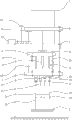
Fig. 3 is the first schematic perspective view of riveted joint parts manufacturing installation embodiment of the present invention;
Fig. 4 is that the A of Fig. 3 is to the view partial graph;
Fig. 5 is the schematic diagram of Fig. 3 or Fig. 4.
In above accompanying drawing: 1. descend hydraulic driver; 2. Workpiece carrier platform; 3. jaw pushing mechanism; 4. vertical frame; 5. support platform; 6. the first pressing down section; 7. the second pressing down section; 8. stop part; 9. the first limiting section; 10. the second limiting section; 11. gripping arm; 12. elastic component; 13. workpiece fixed jig; 14. kind is switched cylinder; 15. bolt; 16. cam; 17. thimble; 18. stage clip; 19. card base; 20. arc tool; 21. motor shell.
The specific embodiment
The invention will be further described below in conjunction with drawings and Examples:
Embodiment: shown in accompanying drawing 3~5, a kind of riveted joint parts manufacturing installation comprises frame, lower hydraulic driver 1 and Workpiece carrier platform 2, also comprises press mechanism, clip claw mechanism and jaw pushing mechanism 3;
Described frame comprises the support platform 5 on vertical frame 4 and vertical frame 4, and described lower hydraulic driver 1 is installed on support platform 5, and the drive end of lower hydraulic driver 1 stretches out down;
Described press mechanism comprises the first pressing down section 6, the second pressing down section 7, stop part 8, the first limiting section 9 and the second limiting section 10, lower hydraulic driver 1 is oil cylinder, the oil cylinder lower end of the guide rod fixed connector that is threaded, the first pressing down section 6 is connected with oil cylinder by the connector briquetting that is fixed thereon, so that the first pressing down section 6 is fixed on the drive end of oil cylinder; Described the second pressing down section 7 is positioned at the below of the first pressing down section 6 and both slide up and down connection, break away from first pressing down section 6 position the second pressing down sections 7 and hang on the first pressing down section 6 through stop part 8 sliding into the second pressing down section 7, be specially: the second pressing down section 7 upsides are fixed a vertical axis of guide, this axis of guide protrudes upward and passes the first rear connection one ring baffle of pressing down section 6, this ring baffle is stop part 8, and the setting of the axis of guide makes the second pressing down section 7 slide up and down with the first pressing down section 6 to be connected.
Described the second pressing down section 7 extends upward and forms described the first limiting section 9, the first limiting section 9 is positioned at support platform 5 tops, be provided with some bolts 15 on support platform 5, the second pressing down section 7 is restricted with respect to moving downward of support platform 5 when the first limiting section 9 comes downwards to the bolt 15 that contacts on support platform 5.Be specially, the second pressing down section 7 is through guide pillar this first limiting section 9 that is rigidly connected, and this first limiting section 9 is a plate body, and plate body is positioned at the top of support platform 5.Simultaneously, the plate body of the first limiting section 9 can carry out motion guide at vertical direction by linear bearing and frame, guarantees that the first limiting section 9 and the second pressing down section 7 that connects thereof all carry out the motion of vertical direction accurately.
Be provided with described the second limiting section 10 between the first pressing down section 6 and the second pressing down section 7, the first pressing down section 6 with the second pressing down section 7 when the second limiting section 10 contacts, the first pressing down section 6 is restricted with respect to the second moving downward of pressing down section 7.Be specifically as follows, be provided with bolt corresponding to vertical direction at the second pressing down section 7 with the first pressing down section 6, when 2 bolts whens contact, the first pressing down section is stopped by the second pressing down section and stops relative motion.
Described clip claw mechanism comprises two gripping arms 11, and these two gripping arms 11 all are hinged on the second pressing down section 7, and two gripping arms 11 can swing between a crawl position and an off-position around the jointed shaft on the second pressing down section 7; Described jaw pushing mechanism 3 is positioned on the first pressing down section 6, is swung towards the crawl position by the off-position in order to promote two gripping arms 11; Effect has an elastic component 12 between two gripping arms 11 and the second pressing down section 7, so that two gripping arms 11 return back to the off-position by the crawl position;
Described Workpiece carrier platform 2 is positioned at below clip claw mechanism.
The second pressing down section 7 connects a workpiece fixed jig 13 through a spring, and the profile of this workpiece fixed jig 13 coordinates with riveted joint parts to be manufactured, rivets teetertottering of parts in order to flexible restriction when working.Can fix an axis of guide on workpiece fixed jig 13, the axis of guide protrudes upward and is carried on the second pressing down section 7 through linear bearing and baffle ring, firmware fixed jig 13 can be moved up and down with respect to the second pressing down section 7, and the axis of guide that prevents firmware fixed jig 13 is because the gravity landing goes out the second pressing down section 7.Spring housing is located at outside the axis of guide, and spring contraction presses down parts to be riveted are flexible when workpiece fixed jig 13 is squeezed, and avoids it to teetertotter, and prevents the position skew.
Manufacturing installation also comprises kind switching cylinder 14 bolt 15 different with some height of being located on support platform 5, this kind is switched cylinder 14 and is installed on support platform 5, bolt 15 can be slidably connected on support platform 5 through the slide block slide rail, each bolt 15 all can switch cylinder 14 by kind and drive and move to the position that coordinates with the first limiting section 9, is restricted with respect to moving downward of support platform 5 so that be in differing heights position the second pressing down section 7 at the second pressing down section 7 with respect to support platform 5.
Two gripping arms 11 are all that the middle part is hinged on the second pressing down section 7, and the hinged cam 16 in equal upper end;
Described jaw pushing mechanism 3 is a thimble 17, and this thimble 17 upper ends are fixed on the first pressing down section 6, and it is conical that the lower end is;
When the first pressing down section 6 descending with respect to the second pressing down section 7, thimble 17 inserts between two gripping arm 11 upper ends the lower end of thimble 17 towards two gripping arms 11 motions, the cam 16 of two gripping arm 11 upper ends promotes through the conical lower end of thimble 17, drives two gripping arms 11 and is swung towards the crawl position by the off-position.Be specifically as follows, the off-position, two gripping arms 11 are splayed, and in the crawl position, two gripping arms 11 are herringbone.
Between the first pressing down section 6 and the second pressing down section 7, effect has a stage clip 18, and this stage clip 18 vertically acts on, and this stage clip 18 is in compressive state, and this stage clip 18 namely is set on the axis of guide between the second pressing down section 7 and the first pressing down section 6.
Above-described embodiment only is explanation technical conceive of the present invention and characteristics, and its purpose is to allow person skilled in the art scholar can understand content of the present invention and implement according to this, can not limit protection scope of the present invention with this.All equivalences that Spirit Essence is done according to the present invention change or modify, within all should being encompassed in protection scope of the present invention.
Claims (6)
1. a riveted joint parts manufacturing installation, comprise frame, lower hydraulic driver (1) and Workpiece carrier platform (2), it is characterized in that: also comprise press mechanism, clip claw mechanism and jaw pushing mechanism (3);
Described frame comprises the support platform (5) on vertical frame (4) and vertical frame (4), and described lower hydraulic driver (1) is installed on support platform (5), and the drive end of lower hydraulic driver (1) stretches out down;
Described press mechanism comprises the first pressing down section (6), the second pressing down section (7), stop part (8), the first limiting section (9) and the second limiting section (10), and wherein the first pressing down section (6) is fixed on the drive end of described lower hydraulic driver (1); Described the second pressing down section (7) is positioned at the below of the first pressing down section (6) and both slide up and down connection, breaks away from the first pressing down section (6) position the second pressing down section (7) and hangs on the first pressing down section (6) through stop part (8) sliding into the second pressing down section (7);
Described the second pressing down section (7) extends upward and forms described the first limiting section (9), the first limiting section (9) is positioned at above support platform (5), and the second pressing down section (7) is restricted with respect to moving downward of support platform (5) when the first limiting section (9) comes downwards to contact support platform (5);
Be provided with described the second limiting section (10) between the first pressing down section (6) and the second pressing down section (7), through the second limiting section (10) when contacting, the first pressing down section (6) is restricted with respect to moving downward of the second pressing down section (7) at the first pressing down section (6) and the second pressing down section (7);
Described clip claw mechanism comprises two gripping arms (11), and these two gripping arms (11) all are hinged on the second pressing down section (7), and two gripping arms (11) can swing between a crawl position and an off-position around the jointed shaft on the second pressing down section (7); Described jaw pushing mechanism (3) is positioned on the first pressing down section (6), is swung towards the crawl position by the off-position in order to promote two gripping arms (11); Effect has an elastic component (12) between two gripping arms (11) and the second pressing down section (7), so that two gripping arms (11) return back to the off-position by the crawl position;
Described Workpiece carrier platform (2) is positioned at below clip claw mechanism.
2. manufacturing installation according to claim 1, it is characterized in that: described lower hydraulic driver (1) is oil cylinder.
3. manufacturing installation according to claim 1, it is characterized in that: described the second pressing down section (7) connects a workpiece fixed jig (13) through a spring, the profile of this workpiece fixed jig (13) coordinates with riveted joint parts to be manufactured, in order to teetertottering of flexible restriction riveted joint parts when working.
4. manufacturing installation according to claim 1, it is characterized in that: also comprise kind switching cylinder (14) bolt (15) different with some height of being located on support platform (5), this kind is switched cylinder (14) and is installed on support platform (5), bolt (15) is slidably connected on support platform (5), each bolt (15) all can switch cylinder (14) driving by kind and move to the position that coordinates with the first limiting section (9), be restricted with respect to moving downward of support platform (5) so that be in differing heights position the second pressing down section (7) at the second pressing down section (7) with respect to support platform (5).
5. manufacturing installation according to claim 1 is characterized in that: described two gripping arms (11) are all that the middle part is hinged on the second pressing down section (7), and equal hinged cams in upper end (16);
Described jaw pushing mechanism (3) is a thimble (17), and this thimble (17) upper end is fixed on the first pressing down section (6), and it is conical that the lower end is;
When the first pressing down section (6) descending with respect to the second pressing down section (7), thimble (17) makes between insertion two gripping arms (11) upper end, lower end of thimble (17) towards two gripping arms (11) motion, the cam (16) of two gripping arms (11) upper end promotes through the conical lower end of thimble (17), drives two gripping arms (11) and is swung towards the crawl position by the off-position.
6. manufacturing installation according to claim 1 is characterized in that: between described the first pressing down section (6) and the second pressing down section (7), effect has a stage clip (18), and this stage clip (18) vertically acts on, and this stage clip (18) is in compressive state.
Priority Applications (1)
| Application Number | Priority Date | Filing Date | Title |
|---|---|---|---|
| CN201310006172.5A CN103084493B (en) | 2013-01-08 | 2013-01-08 | Riveting part manufacturing device |
Applications Claiming Priority (1)
| Application Number | Priority Date | Filing Date | Title |
|---|---|---|---|
| CN201310006172.5A CN103084493B (en) | 2013-01-08 | 2013-01-08 | Riveting part manufacturing device |
Publications (2)
| Publication Number | Publication Date |
|---|---|
| CN103084493A true CN103084493A (en) | 2013-05-08 |
| CN103084493B CN103084493B (en) | 2014-12-31 |
Family
ID=48197907
Family Applications (1)
| Application Number | Title | Priority Date | Filing Date |
|---|---|---|---|
| CN201310006172.5A Active CN103084493B (en) | 2013-01-08 | 2013-01-08 | Riveting part manufacturing device |
Country Status (1)
| Country | Link |
|---|---|
| CN (1) | CN103084493B (en) |
Cited By (4)
| Publication number | Priority date | Publication date | Assignee | Title |
|---|---|---|---|---|
| CN103736868A (en) * | 2013-12-19 | 2014-04-23 | 宁波天龙电子股份有限公司 | Device capable of decomposing pressure of rotary table |
| CN106914551A (en) * | 2017-03-09 | 2017-07-04 | 百色百大之窗工程装饰有限责任公司 | 360 degree of Buddha's warrior attendant gauze crimping machines |
| CN107971726A (en) * | 2017-11-21 | 2018-05-01 | 中山市科力高自动化设备有限公司 | A kind of press-in device applied on turning machine bushing press |
| CN109550856A (en) * | 2018-12-30 | 2019-04-02 | 江苏唯侓机器人科技有限公司 | Pressure riveting device and method for pressing to materials and parts |
Citations (4)
| Publication number | Priority date | Publication date | Assignee | Title |
|---|---|---|---|---|
| US6546609B1 (en) * | 2001-12-12 | 2003-04-15 | Hon Hai Precision Ind. Co., Ltd. | Automatic riveting apparatus |
| US20030196534A1 (en) * | 2002-03-19 | 2003-10-23 | Heiko Schmidt | Punching head, machining tool with one such punching head and machining device with one such punching head or machining tool |
| CN102397952A (en) * | 2011-11-17 | 2012-04-04 | 苏州睿昕汽车配件有限公司 | Hydraulic-pressure riveting edge machine equipped with a pressure gage |
| CN203076468U (en) * | 2013-01-08 | 2013-07-24 | 苏州凯蒂亚半导体制造设备有限公司 | Riveted part manufacturing device |
-
2013
- 2013-01-08 CN CN201310006172.5A patent/CN103084493B/en active Active
Patent Citations (4)
| Publication number | Priority date | Publication date | Assignee | Title |
|---|---|---|---|---|
| US6546609B1 (en) * | 2001-12-12 | 2003-04-15 | Hon Hai Precision Ind. Co., Ltd. | Automatic riveting apparatus |
| US20030196534A1 (en) * | 2002-03-19 | 2003-10-23 | Heiko Schmidt | Punching head, machining tool with one such punching head and machining device with one such punching head or machining tool |
| CN102397952A (en) * | 2011-11-17 | 2012-04-04 | 苏州睿昕汽车配件有限公司 | Hydraulic-pressure riveting edge machine equipped with a pressure gage |
| CN203076468U (en) * | 2013-01-08 | 2013-07-24 | 苏州凯蒂亚半导体制造设备有限公司 | Riveted part manufacturing device |
Cited By (8)
| Publication number | Priority date | Publication date | Assignee | Title |
|---|---|---|---|---|
| CN103736868A (en) * | 2013-12-19 | 2014-04-23 | 宁波天龙电子股份有限公司 | Device capable of decomposing pressure of rotary table |
| CN103736868B (en) * | 2013-12-19 | 2015-11-11 | 宁波天龙电子股份有限公司 | A kind of device that can decompose pressure of rotary table |
| CN106914551A (en) * | 2017-03-09 | 2017-07-04 | 百色百大之窗工程装饰有限责任公司 | 360 degree of Buddha's warrior attendant gauze crimping machines |
| CN106914551B (en) * | 2017-03-09 | 2018-10-26 | 百色百大之窗工程装饰有限责任公司 | 360 degree of Buddha's warrior attendant gauze crimping machines |
| CN107971726A (en) * | 2017-11-21 | 2018-05-01 | 中山市科力高自动化设备有限公司 | A kind of press-in device applied on turning machine bushing press |
| CN107971726B (en) * | 2017-11-21 | 2019-08-02 | 中山市科力高自动化设备有限公司 | A kind of press-in device applied on turning machine bushing press |
| CN109550856A (en) * | 2018-12-30 | 2019-04-02 | 江苏唯侓机器人科技有限公司 | Pressure riveting device and method for pressing to materials and parts |
| CN109550856B (en) * | 2018-12-30 | 2023-10-17 | 江苏唯侓机器人科技有限公司 | Pressing riveting device and method for pressing riveting of material piece |
Also Published As
| Publication number | Publication date |
|---|---|
| CN103084493B (en) | 2014-12-31 |
Similar Documents
| Publication | Publication Date | Title |
|---|---|---|
| CN104722629B (en) | A kind of fully automatic high-speed perforating press | |
| CN106827618B (en) | A kind of three-dimensional pressure maintaining equipment | |
| CN103084493B (en) | Riveting part manufacturing device | |
| CN106346283A (en) | Pipe fitting clamping device | |
| CN204602997U (en) | Fully automatic high-speed perforating press | |
| CN201423577Y (en) | Expansion sleeve fixture | |
| CN205254472U (en) | Gasbag component assembly anchor clamps | |
| CN206595348U (en) | Battery core edge sealing and lug leveling fixture | |
| CN101844493B (en) | Tyre dismounting machine | |
| CN109807655B (en) | Centering device for leveling | |
| CN106862319B (en) | Battery core edge sealing and tab flatten manipulator | |
| CN204603114U (en) | Clip type draw-gear | |
| CN203076468U (en) | Riveted part manufacturing device | |
| CN104858271A (en) | Pipe fitting bending device | |
| CN102527842A (en) | Wedge mechanism with forced return device | |
| CN204545183U (en) | A kind of pipe fitting expanding device | |
| CN206898108U (en) | Battery core edge sealing and lug leveling manipulator | |
| CN109909777B (en) | Workpiece positioning and pressing device for automatic production line | |
| CN206595349U (en) | Battery core edge sealing and lug apparatus for leveling | |
| CN107538253B (en) | Push type translational clamp and use method thereof | |
| CN104722697A (en) | Lamp nameplate pressure riveting fixture | |
| CN107414537A (en) | Process the fixture of circular steel column | |
| CN210173923U (en) | Diamond wire saw connects pressing tongs | |
| CN209998684U (en) | Horizontal press-fitting equipment for fixing ring of shock absorber | |
| CN208033985U (en) | A kind of catalyst converter flange positioning clamping device for preventing being mingled with spatter |
Legal Events
| Date | Code | Title | Description |
|---|---|---|---|
| C06 | Publication | ||
| PB01 | Publication | ||
| C10 | Entry into substantive examination | ||
| SE01 | Entry into force of request for substantive examination | ||
| C14 | Grant of patent or utility model | ||
| GR01 | Patent grant |