CN102801818A - Universal sensor interface acquisition system based on ZigBee technology - Google Patents
Universal sensor interface acquisition system based on ZigBee technology Download PDFInfo
- Publication number
- CN102801818A CN102801818A CN2012103013377A CN201210301337A CN102801818A CN 102801818 A CN102801818 A CN 102801818A CN 2012103013377 A CN2012103013377 A CN 2012103013377A CN 201210301337 A CN201210301337 A CN 201210301337A CN 102801818 A CN102801818 A CN 102801818A
- Authority
- CN
- China
- Prior art keywords
- module
- sensor
- transducer
- line
- zigbee
- Prior art date
- Legal status (The legal status is an assumption and is not a legal conclusion. Google has not performed a legal analysis and makes no representation as to the accuracy of the status listed.)
- Granted
Links
Images


Abstract
The invention relates to a universal sensor interface acquisition system based on a ZigBee technology, which belongs to the field of wireless communication and electronic technologies. The universal sensor interface acquisition system comprises a ZigBee module, a power supply module, a universal sensor interface module and a digital packaging sensor module, wherein I/O (input/output) ports of the ZigBee module are simulated to a clock line and a data line of a serial transmission bus by a microcontroller of the ZigBee module and are connected with the universal sensor interface module; the power supply module supplies power to the ZigBee module through a power supply line and a grounding line; the universal sensor interface module comprises the clock line, the power supply line, the grounding line and the data line; and the digital packaging sensor module is connected with the universal sensor interface module by the clock line, the power supply line, the grounding line and the data line. The universal sensor interface acquisition system realizes the plug and play of a special packaged sensor by virtue of a universal sensor interface, and avoids circuit changes in acquisition of different types of data; and the compatibility and the validity of the system are improved, and the cost of the system is reduced.
Description
Technical field
The present invention relates to a kind of acquisition system based on the ZigBee technology, particularly a kind of transducer general-purpose interface belongs to radio communication and electronic technology field.
Background technology
The development of technology such as microelectric technique, computing technique and radio communication has promoted the development of low-power consumption Multifunction Sensor, make its can the integrated information collection in small volume, multiple functions such as data processing and radio communication.Wireless sensor network is exactly that in logic information world and objectively physical world are merged, and realizes collection, transmission, the processing of objective physical world information.The data acquisition unit sensor node of wireless sensor network mainly is made up of sensor assembly, processor module, wireless communication module and energy supply module four parts.The ZigBee technology is a kind of short distance, low complex degree, low-power consumption, low data rate, two-way wireless communication technology or radio network technique cheaply, is the communication technology of one group of relevant networking, safety and application software aspect of developing based on IEEE 802.15.4 wireless standard.Even yet there is following problem in the data acquisition system based on wireless sensor network of China at present:
1. sensor node complex structure.Sensor node generally is made up of four modules in wireless sensor network: sensor assembly, processor module, wireless communication module and energy supply module; Need in the practical application to require to choose various chips to each module; The pin that also will consider chip chamber simultaneously connects and peripheral circuit; Cause the complicated circuit line many, be difficult for change in case connect.
2. transducer is of a great variety, and every kind of transducer all needs a kind of connecting circuit.Can mark off diversified transducer according to the difference of measurand type, the difference of operation principle, the difference of output signal type; Each transducer all have oneself pin configuration, work schedule, with the method for attachment of processor; When data acquisition system need be gathered several data, need to the different connecting circuit of no sensor design.
3. the sensor design disunity lacks versatility.Even the transducer of same kind also has different pin designs and output signal type; Have plenty of three pins, have plenty of four pins, have plenty of numeral output, have plenty of simulation output; Cause when need gathering a kind of physical data and also will consider multiple connected mode, lack versatility.
4. can't realize the plug and play of transducer.In case the welding of the circuit of sensor node is accomplished; Only if just can't change circuit welding circuit again again; And sensor node need be gathered different physical datas through emat sensor more generally speaking; Therefore need constantly change, welding circuit, lack the plug and play interface of a transducer.
5. poor compatibility, cost is high.Data acquisition system based on wireless sensor network need be gathered various types of data; The corresponding different sensor of different data acquisitions, different connecting circuits, continuous change, welding circuit; System compatibility is poor, has also wasted unnecessary resource simultaneously.
Summary of the invention
The present invention is directed to the defective that prior art exists; A kind of general-purpose interface collection system of sensor based on the ZigBee technology is provided; The simple connecting line of system configuration is few, need not to change circuit, and the transducer of unified encapsulation is through transducer general-purpose interface plug and play; Can measure several data, cost is low, efficient is high, compatibility is good.
Technical scheme of the present invention is:
The invention provides a kind of general-purpose interface collection system of sensor based on the ZigBee technology, this system is made up of ZigBee module 1, power module 2, transducer common interface module 3 and digital encapsulated sensor module 4 four parts.
ZigBee module 1 is responsible for the operation of control whole sensor node, comprises the data that transmission control command, storage and processing itself are gathered; Be responsible for carrying out radio communication exchange of control information and transmitting-receiving image data with other sensor nodes.ZigBee module 1 is quoted power pins, grounding pin and two I/O pins of ZigBee chip, as power line, earth connection, clock line and data wire, and is connected with transducer common interface module 3 with data wire through clock line, power line, earth connection.Wherein power line provides operating voltage with connecting wires for transducer common interface module 3; ZigBee module 1 is modeled as the serial transmission bus through microcontroller with two I/O pins of port one, is respectively clock line and data wire, is used to transmit the Monitoring Data of control command and collection.
Transducer common interface module 3 comprises clock line, power line, connects wires and data wire, and profile adopts the PIN jack.Transducer common interface module 3 is connected with digital encapsulated sensor module 4 with data wire through clock line, power line, earth connection.Wherein the PIN jack adopts single four hole jack forms, and No. 1 jack is that clock line, No. 2 jacks are that power line, No. 3 jacks are that earth connection, No. 4 jacks are data wire, and the jack spacing is 2.54mm.Transducer common interface module 3 provides the jack of a plug and play for the digital encapsulated sensor of multi-functional unification, and is convenient, fast, efficient is high.
Numeral encapsulated sensor module 4 is encapsulated in transducer and peripheral circuit thereof on the pcb board, and draws four pins and be respectively clock line, power line, earth connection and data wire.Transducer is responsible for perception, is gathered the monitoring information in the monitored area, and peripheral circuit is in order to guarantee the numeral output of digital encapsulated sensor module 4.When the transducer of encapsulation is the numeric type transducer, can be according to directly encapsulation of four lines output; When the transducer of encapsulation is the analogue type transducer, need transducer be connected with the such peripheral circuit of A/D converter and serial line interface, guarantee the output of four lines numeral.Wherein power line and earth connection provide the operating voltage of 3V for digital encapsulated sensor module 4 through transducer common interface module 3; The cooperatively interact transmission of Monitoring Data of the transmission of accomplishing control command and collection of clock line and data wire.The profile of numeral encapsulated sensor module 4 adopts the single PIN contact pin of four pins as pin; No. 1 pin is that clock line, No. 2 pins are that power line, No. 3 pins are that earth connection, No. 4 pins are data wire; Pin-pitch is 2.54mm; Pin length is 6.35mm, and pin size is consistent with the PIN jack of transducer common interface module 3, realizes the plug and play seamless link.
The invention has the beneficial effects as follows:
1. node circuit of the present invention replaces processor module and two modules of wireless communication module with a ZigBee module; Entire circuit has only clock line, power line, earth connection and four connecting lines of data wire; Simple in structure clear; Reduced production cost, and accomplished the function that needs most with minimum module and connecting line.
2. transducer general-purpose interface of the present invention is that various transducer places in circuit provide a socket, chooses different sensor according to the difference of measurement data type and inserts socket, need not to change circuit, and is convenient and swift.
3. digital encapsulated sensor of the present invention is for realizing the plug-and-play feature to general-purpose interface, and the unified encapsulation of hardware specification that requires according to invention before dispatching from the factory and timing sequence specification realizes that the encapsulation of transducer is unitized, is easy to install and improved utilance.
4. the present invention is applicable to the acquisition system of gathering the polytype data simultaneously, only need change the special package transducer to the different acquisition task, need not other operations, and is efficient, quick, economize on resources.
Description of drawings
Fig. 1 is the structural representation based on the technological general-purpose interface collection system of sensor of ZigBee provided by the invention;
Fig. 2 is the overall dimension sketch map of transducer general-purpose interface provided by the invention and digital encapsulated sensor;
Wherein: Fig. 2 (a) is the overall dimension sketch map of transducer general-purpose interface; Fig. 2 (b) is the overall dimension sketch map of digital encapsulated sensor;
A kind of structural representation that Fig. 3 provides for the embodiment of the invention based on the technological general-purpose interface collection system of sensor of ZigBee;
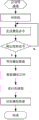
The data acquisition program flow chart of the digital hygro sensor DHT90 that Fig. 4 provides for the embodiment of the invention.
Embodiment
Below in conjunction with accompanying drawing a concrete execution mode of the present invention is described.
Structural representation based on the technological general-purpose interface collection system of sensor of ZigBee of the present invention is as shown in Figure 1.Comprise ZigBee module 1, power module 2, transducer common interface module 3 and digital encapsulated sensor module 4; ZigBee module 1 is connected with transducer common interface module 3 with data wire through clock line, power line, earth connection; Power module 2 is connected with ZigBee module 1 with earth connection through power line; Transducer common interface module 3 is connected with digital encapsulated sensor module 4 with data wire through clock line, power line, earth connection.
Accompanying drawing 3 is based on an embodiment of the general-purpose interface collection system of sensor of ZigBee technology:
Select for use the HFZ-CC2430EM-22 module as ZigBee module 1, be responsible for the operation of control whole node, transmitting control commands, processing and transmission image data, and form the network system of the self-organizing of a multi-hop with other node radio communications.This module adopts the ZigBee radio frequency chip CC2430 of Texas Instrument (TI), and integrated high-performance 8051 kernels, ADC, USART etc. on the sheet support the ZigBee protocol stack.This module is drawn 24 pins altogether and is respectively 19 I/O mouths, comprises all P1 mouths, P0 mouth and P2_0, P2_1, three mouths of P2_2,2 power pins, and 2 grounding pins, a reset pin, pin-pitch is 2.54mm.Wherein 8051 integrated microcontrollers are modeled as the serial transmission bus as clock line and data wire with P1_1 that draws and P1_3 mouth on the CC2430 chip, are connected with No. 4 jacks with No. 1 jack of transducer common interface module 3 respectively; Power pins is connected with No. 3 jacks with No. 2 jacks of transducer common interface module 3 respectively with grounding pin.
Select two joint No.5 cells power module 2 the most for use, be responsible for the operating voltage that ZigBee module 1, transducer common interface module 3 and digital encapsulated sensor module 4 provide 3V.Two joint No.5 cell series connection, positive pole is connected with the power pins of HFZ-CC2430EM-22 module, and negative pole is connected with the grounding pin of HFZ-CC2430EM-22 module.
The PIN jack of selecting single four holes for use is as transducer common interface module 3, and the transducer that is responsible for the numeral encapsulation provides the socket of a plug and play.Wherein No. 1 jack is that clock line, No. 2 jacks are that power line, No. 3 jacks are that earth connection, No. 4 jacks are data wire, and the jack spacing is 2.54mm, and the overall dimension sketch map is consulted shown in Fig. 2 (a).Wherein No. 1 jack, No. 2 jacks, No. 3 jacks, No. 4 jacks are connected with No. 1 pin of digital encapsulated sensor module 4, No. 2 pins, No. 3 pins, No. 4 pins respectively.
The digital hygro sensor DHT90 that selects the pin type encapsulation for use is responsible for perception, collection and the conversion of image data as digital encapsulated sensor module 4.DHT90 comprises the temperature element that a capacitive character condensate hygrometric senser, are processed with gap material and on same chip, realizes seamless link with 14 A/D converter and serial interface circuit; Provide four pins single pin package; Be followed successively by pin to 4 pin from top to bottom No. 1; Wherein No. 1 pin is that clock line SCK, No. 2 pins are that power line VDD, No. 3 pins are data wire DATA for the GND that connects wires, No. 4 pins, and pin-pitch is 2.54mm, and pin length is 6.35mm; Sensor package is on pcb board, and the overall dimension sketch map is consulted shown in Fig. 2 (b).The operating voltage range of DHT90 is 2.4-5.5V, and present embodiment is selected the operating voltage of 3V for use, thereby No. 2 pins are connected with grounding pin with the power pins of HFZ-CC2430EM-22 module with No. 3 jacks with No. 3 pins No. 2 jacks through the PIN jack; No. 1 pin of DHT90 and No. 4 pins are connected corresponding No. 1 to No. 4 jack that inserts the PIN jack of No. 1 to No. 4 pin of DHT90 through No. 1 jack of PIN jack with P1_3 with the P1_0 of HFZ-CC2430EM-22 module with No. 4 jacks.
Accomplish the hardware connection of embodiment according to above method after, begin whole system is carried out software design.Adopt IAREmbedded Workbench (the embedded workbench of IAR) as Software Development Platform, because of its debug function is powerful, friendly interface and being widely used is fit to the embedded OS of exploitation based on 32/16/8 bit microprocessor.IAR integrates C-SPY debugger, Project Manager, file editor, librarian, linker, compilation instrument and C/C++ editing machine.Also have a code optimization device in the IAR software, make the embedded workbench of IAR can generate the FLASH code of reliable and effective for 8051 family chips.The compiler of IAR Embedded Workbench has following characteristics: memorymodel is selected, efficient floating-point support, bottleneck performance evaluation; Break simulation and processing easily; Expander tool and Version Control support are good, and target property expands, complete and standard C compatibility.
Use IAR EW following to the step that the embodiment system develops:
(1) the engineering option is set.
(2) editor and compiling source file generate application file.
(3) linking object module comprises debugging option.
(4) debugging routine is if mistake turns back to the debugging again then of the second step revised file.
(5) after debugging successfully, withdraw from debugging option, accomplish the program of SOC(system on a chip) and download.
The programming of the sensor node in the embodiment system mainly contains two parts to be formed, and a part is responsible for realizing internodal networking and transfer of data that another part is responsible for realizing the collection of sensor monitors data and reading.
The workflow of internodal networking and transfer of data is for carrying out initialization to sensor node earlier; After initialization was accomplished, node sent request signal and adds network, and the method that can adopt father node directly to add network realizes; If sensor node networks successfully; Sensor node begins the object in the monitored area is carried out data acquisition, and it is that telegon sends image data to aggregation node that data acquisition finishes the back, sends the information gathering stage that successfully turns back to afterwards; Continue image data, the continuous image data of going round and beginning again is sent data.
The transmission that integrated 8051 microcontrollers are accomplished control command through cooperatively interacting of clock line and data wire on DHT90 and the CC2430 chip and the transmission of image data.The data acquisition program flow process of Temperature Humidity Sensor DHT90 is consulted shown in Figure 4, and detailed process is: electrifying startup transducer at first makes transducer get into resting state; After transducer starts, send one by microcontroller to transducer and start transmission time sequence, accomplish initial work; After the initialization sequential was sent, microcontroller sent measuring command to transducer, and transducer determines whether to take orders; Confirm to receive after the order, wait for that measurement data finishes according to measurement up to the sensor sheet registration; Restart clock after DATA REASONING finishes, microcontroller reads measurement data, and data read the back sign off that finishes.
Claims (9)
1. the general-purpose interface collection system of sensor based on the ZigBee technology is characterized in that said system is made up of ZigBee module (1), power module (2), transducer common interface module (3) and digital encapsulated sensor module (4); Said ZigBee module (1) is connected with transducer common interface module (3) with data wire through clock line, power line, earth connection; Said power module (2) is connected with ZigBee module (1) with earth connection through power line; Said transducer common interface module (3) is connected with said digital encapsulated sensor module (4) with data wire through clock line, power line, earth connection.
2. according to the described general-purpose interface collection system of sensor of claim 1 based on the ZigBee technology; It is characterized in that; Said ZigBee module (1) is modeled as the serial transmission bus through microcontroller with two I/O pins of port one; Be respectively clock line and data wire, be used to transmit control command and image data; ZigBee module (1) is only quoted power pins, grounding pin and above-mentioned two I/O pins, as power line, earth connection, clock line and data wire.
3. according to the described general-purpose interface collection system of sensor of claim 1, it is characterized in that it is the operating voltage that ZigBee module (1) provides 3V through power line and earth connection that said power module (2) adopts two joint No.5 cells based on the ZigBee technology.
4. according to the described general-purpose interface collection system of sensor based on the ZigBee technology of claim 1, it is characterized in that said transducer common interface module (3) comprises clock line, power line, connects wires and data wire, profile adopts the PIN jack.
5. according to the described transducer common interface module of claim 4 (3); It is characterized in that; Said PIN jack adopts single four hole jack forms, and No. 1 jack is that clock line, No. 2 jacks are that power line, No. 3 jacks are that earth connection, No. 4 jacks are data wire, and the jack spacing is 2.54mm.
6. according to the described general-purpose interface collection system of sensor of claim 1 based on the ZigBee technology; It is characterized in that; Said digital encapsulated sensor module (4) is that transducer and peripheral circuit thereof are encapsulated on the pcb board, and draws four pins and be respectively clock line, power line, earth connection and data wire; The numeral encapsulated sensor module (4) through clock line, power line, connecting wires is connected with transducer common interface module (3) with data wire; Profile adopts the single pin package of four pins; The image data of output is numeral output.
7. according to the described general-purpose interface collection system of sensor of claim 1, it is characterized in that said power line and earth connection provide the operating voltage of 3V for digital encapsulated sensor module (4) through transducer common interface module (3) based on the ZigBee technology; Described clock line and data wire the cooperatively interact transmission of accomplishing control command and the transmission of image data.
8. according to the described general-purpose interface collection system of sensor of claim 6 based on the ZigBee technology; It is characterized in that; The single pin package of said four pins adopts the PIN contact pin as pin; No. 1 pin is that clock line, No. 2 pins are that power line, No. 3 pins are that earth connection, No. 4 pins are data wire, and pin-pitch is 2.54mm, and pin length is 6.35mm.
9. according to the described general-purpose interface collection system of sensor of claim 6, it is characterized in that based on the ZigBee technology, when encapsulated sensor is the numeric type transducer, can be according to directly encapsulation of four lines output; When the transducer of encapsulation is the analogue type transducer, need transducer be connected with serial line interface through A/D converter, guarantee the output of four lines numeral.
Priority Applications (1)
| Application Number | Priority Date | Filing Date | Title |
|---|---|---|---|
| CN201210301337.7A CN102801818B (en) | 2012-08-22 | 2012-08-22 | Universal sensor interface acquisition system based on ZigBee technology |
Applications Claiming Priority (1)
| Application Number | Priority Date | Filing Date | Title |
|---|---|---|---|
| CN201210301337.7A CN102801818B (en) | 2012-08-22 | 2012-08-22 | Universal sensor interface acquisition system based on ZigBee technology |
Publications (2)
| Publication Number | Publication Date |
|---|---|
| CN102801818A true CN102801818A (en) | 2012-11-28 |
| CN102801818B CN102801818B (en) | 2015-05-20 |
Family
ID=47200778
Family Applications (1)
| Application Number | Title | Priority Date | Filing Date |
|---|---|---|---|
| CN201210301337.7A Active CN102801818B (en) | 2012-08-22 | 2012-08-22 | Universal sensor interface acquisition system based on ZigBee technology |
Country Status (1)
| Country | Link |
|---|---|
| CN (1) | CN102801818B (en) |
Cited By (8)
| Publication number | Priority date | Publication date | Assignee | Title |
|---|---|---|---|---|
| CN103458535A (en) * | 2013-08-28 | 2013-12-18 | 北京师范大学 | Low-power-consumption weak signal data acquisition and wireless transmission module |
| CN104376665A (en) * | 2014-11-28 | 2015-02-25 | 中国电子科技集团公司第二十八研究所 | Monitoring node of perimeter protection system of wireless sensor network |
| CN104992551A (en) * | 2015-07-30 | 2015-10-21 | 成都泰盟软件有限公司 | Universal sensor interface |
| CN105812030A (en) * | 2016-03-10 | 2016-07-27 | 东华大学 | Sensor general interface based on low power consumption bluetooth technology |
| CN106707853A (en) * | 2016-12-09 | 2017-05-24 | 广州云雾小桥信息科技有限公司 | Network equipment controller |
| CN107918080A (en) * | 2016-10-11 | 2018-04-17 | 大陆汽车电子(连云港)有限公司 | Sensor connection state detection method, device and sensor |
| CN111127860A (en) * | 2019-12-25 | 2020-05-08 | 重庆特斯联智慧科技股份有限公司 | Sensor access device based on Internet of things |
| CN113467594A (en) * | 2020-03-30 | 2021-10-01 | 北京小米移动软件有限公司 | Connecting module and terminal equipment |
Citations (2)
| Publication number | Priority date | Publication date | Assignee | Title |
|---|---|---|---|---|
| CN201465282U (en) * | 2009-07-13 | 2010-05-12 | 北京交通大学 | Universal modular interface-based wireless sensor network node |
| CN202121791U (en) * | 2011-07-18 | 2012-01-18 | 国电南京自动化股份有限公司 | Modular Zigbee wireless sensor |
-
2012
- 2012-08-22 CN CN201210301337.7A patent/CN102801818B/en active Active
Patent Citations (2)
| Publication number | Priority date | Publication date | Assignee | Title |
|---|---|---|---|---|
| CN201465282U (en) * | 2009-07-13 | 2010-05-12 | 北京交通大学 | Universal modular interface-based wireless sensor network node |
| CN202121791U (en) * | 2011-07-18 | 2012-01-18 | 国电南京自动化股份有限公司 | Modular Zigbee wireless sensor |
Cited By (11)
| Publication number | Priority date | Publication date | Assignee | Title |
|---|---|---|---|---|
| CN103458535A (en) * | 2013-08-28 | 2013-12-18 | 北京师范大学 | Low-power-consumption weak signal data acquisition and wireless transmission module |
| CN103458535B (en) * | 2013-08-28 | 2016-08-10 | 北京师范大学 | A kind of low-power consumption weak signal data acquisition and wireless transport module |
| CN104376665A (en) * | 2014-11-28 | 2015-02-25 | 中国电子科技集团公司第二十八研究所 | Monitoring node of perimeter protection system of wireless sensor network |
| CN104992551A (en) * | 2015-07-30 | 2015-10-21 | 成都泰盟软件有限公司 | Universal sensor interface |
| CN104992551B (en) * | 2015-07-30 | 2018-05-18 | 成都泰盟软件有限公司 | Universal sensor interface |
| CN105812030A (en) * | 2016-03-10 | 2016-07-27 | 东华大学 | Sensor general interface based on low power consumption bluetooth technology |
| CN107918080A (en) * | 2016-10-11 | 2018-04-17 | 大陆汽车电子(连云港)有限公司 | Sensor connection state detection method, device and sensor |
| CN107918080B (en) * | 2016-10-11 | 2020-12-18 | 大陆汽车电子(连云港)有限公司 | Sensor connection state detection method and device and sensor |
| CN106707853A (en) * | 2016-12-09 | 2017-05-24 | 广州云雾小桥信息科技有限公司 | Network equipment controller |
| CN111127860A (en) * | 2019-12-25 | 2020-05-08 | 重庆特斯联智慧科技股份有限公司 | Sensor access device based on Internet of things |
| CN113467594A (en) * | 2020-03-30 | 2021-10-01 | 北京小米移动软件有限公司 | Connecting module and terminal equipment |
Also Published As
| Publication number | Publication date |
|---|---|
| CN102801818B (en) | 2015-05-20 |
Similar Documents
| Publication | Publication Date | Title |
|---|---|---|
| CN102801818B (en) | Universal sensor interface acquisition system based on ZigBee technology | |
| CN110166975B (en) | Agricultural Internet of things sensor communication method based on wireless network and raspberry-set node | |
| US8948184B2 (en) | Embedded system development platform | |
| CN101902831B (en) | Node in wireless sensor network, applicable to detection of mechanical equipment vibration | |
| CN103235749A (en) | FPGA-based sensor network SoC proto verification platform | |
| CN101000597A (en) | IP kernel of embedded Java processor based on AMBA | |
| CN101631394A (en) | Multi-interface coordinator of wireless sensor network | |
| CN104486419A (en) | Network firmware updating method based on FT platform | |
| CN103945017A (en) | Automatic mapping technique method and converting device based on Modbus-ZigBee protocol link addresses | |
| CN105335548A (en) | MCU simulation method for ICE | |
| CN103560938A (en) | Industrial Ethernet and HART bus protocol conversion board card | |
| CN205983198U (en) | Cross -platform PLC board level frock test system based on QT | |
| CN203260028U (en) | Sensor network SoC prototype verification platform based on FPGA | |
| CN203596016U (en) | Universal port for communication of sensor and micro controller | |
| CN207339992U (en) | Stationary nodes automated test device | |
| CN110532010A (en) | A kind of method of the volume production device upgrading solid state hard disk of band USB | |
| CN201000625Y (en) | Field programmable gate array online configuration device | |
| CN203849370U (en) | Boundary scan testing apparatus | |
| CN209842365U (en) | Signal processing system | |
| CN203563088U (en) | Protocol conversion board of industrial Ethernet and HART bus | |
| CN103150952A (en) | Reconfigurable electronic design automation (EDA) experimental platform | |
| CN110413550B (en) | Chip serial port program downloading control circuit | |
| CN207623770U (en) | Machine is controlled in a kind of intelligence | |
| CN101719053A (en) | Method for reading IIC storage card by SPI interface | |
| KR200439053Y1 (en) | Device having reconfigurable chip for interacting with processor using serial communication channel and system thereof |
Legal Events
| Date | Code | Title | Description |
|---|---|---|---|
| C06 | Publication | ||
| PB01 | Publication | ||
| C10 | Entry into substantive examination | ||
| SE01 | Entry into force of request for substantive examination | ||
| C14 | Grant of patent or utility model | ||
| GR01 | Patent grant |