CN102797467A - Automatic rock drilling device special for tunnel excavation - Google Patents
Automatic rock drilling device special for tunnel excavation Download PDFInfo
- Publication number
- CN102797467A CN102797467A CN201210282860XA CN201210282860A CN102797467A CN 102797467 A CN102797467 A CN 102797467A CN 201210282860X A CN201210282860X A CN 201210282860XA CN 201210282860 A CN201210282860 A CN 201210282860A CN 102797467 A CN102797467 A CN 102797467A
- Authority
- CN
- China
- Prior art keywords
- arm
- rock drilling
- pushing ram
- platform
- hand
- Prior art date
- Legal status (The legal status is an assumption and is not a legal conclusion. Google has not performed a legal analysis and makes no representation as to the accuracy of the status listed.)
- Granted
Links
Images


Abstract
The invention relates to an automatic rock drilling device special for tunnel excavation, which has high rock drilling efficiency, is safe for using and contributes to saving time and construction cost. The automatic rock drilling device comprises a control stand, a support frame, a power device, a movable carrier and rock drilling equipment, wherein the support frame is arranged on the carrier; the power device, the control stand and the rock drilling equipment are arranged on the support frame; the power device is connected with the rock drilling equipment through a lead; the control stand is connected with the power device and the rock drilling equipment through leads respectively; the support frame is a square frame body; the support frame body is provided with at least one group of platforms capable of extending and contracting towards both sides; the rock drilling equipment comprises one or more groups of mechanical arms and drill bits arranged on the mechanical arms; one end of each mechanical arm is connected to the frame body; and the other end of each mechanical arm is provided with a drill bit. The automatic rock drilling device has the advantages of high rock drilling efficiency, use safety, saving in time and construction cost, and the like.
Description
Technical field
The present invention relates to rock drilling equipment field, tunnel, particularly a kind of safe in utilization, efficient, save time and automatic rock drilling device that the dedicated tunnel of construction cost is excavated.
Background technology
At present tunnel drill mainly be adopt one movably carrier and the arm hand that directly is installed on the carrier excavate, in general, the removable carrier that adopts here is small-sized vehicle; In order to guarantee balance, generally also only load a spot of arm hand, and the scale of arm hand is also less; Such tunnel rock drilling equipment, in the process of rock drilling, exist the rock drilling time long, rock penetration performance is slow; In the rock drilling process, if dangerous (generally be Tunnel ahead cave in cause the vehicle major part to be buried) taken place, the personnel of the motion arm manual task in vehicle are buried easily; The rate of surviving is low, simultaneously owing to existing tunnel hammer drill function singleness, in the rock drilling process; Personnel to rock stratum research must follow the rear view of vehicle operation, and researcher's health, the safety of rock stratum is caused bigger injury.
Summary of the invention
The object of the present invention is to provide a kind of rock penetration performance high, safe in utilization, save time and automatic rock drilling device that the dedicated tunnel of construction cost is excavated.
The objective of the invention is to realize like this: it comprises console, bracing frame, power set, movably carrier, rock drilling equipment; Described bracing frame is installed on the carrier; Power set, console, rock drilling equipment are installed on the bracing frame; Power set are connected through lead with rock drilling equipment, and console is connected with power set, rock drilling equipment respectively through lead;
Described bracing frame is a square support body, and on the bracing frame support body, being provided with at least one group can be to the flexible platform in both sides;
Described rock drilling equipment comprises one group or above mechanical arm and constitutes with the drill bit that is installed on the mechanical arm that an end of mechanical arm is connected in support body, and the other end of mechanical arm is provided with drill bit.
The present invention has following advantage: 1 rock penetration performance is high; Pass through configure chassis; And the vehicle equipment of configuration delivery frame, increase the carrying capacity of rock drilling device, so can on the rock drilling frame, assemble many mechanical arms; And disposed many consoles and controlled, handle these mechanical arms, can improve rock penetration performance and rock drilling quality like this; 2 is safe in utilization no matter for the personnel of operating personnel, still rock stratum research, owing to increased bracing frame, promptly expanded whole bracing frame; Through the telescopic job platform in bracing frame top, guaranteed personnel's safety, avoid being injured by the rock that the rock stratum comes off; In the landslide of rock stratum, if part is buried, vehicle also can directly roll away from; If bury fully, the personnel that buried can guarantee that also enough spaces wait for rescue.3 save time and construction cost, save time, and practice thrift the whole duration exactly, and in a single day the duration shortens, and each link all can be affected in the whole engineering, and the wage that therefore can send out a large amount of is less practiced thrift cost.
Description of drawings
Fig. 1 is an overall structure sketch map of the present invention;
Fig. 2 is the structural representation that the bracing frame of console, platform, power set is installed;
Fig. 3 is the left view of Fig. 2;
Fig. 4 is the structural representation that has the platform structure bracing frame;
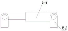
The structural representation of Fig. 5 first pushing ram;
Fig. 6 is the mechanical arm structural representation behind the drill bit;
Fig. 7 is the mechanical arm elevation behind the drill bit;
Fig. 8 is the mechanical arm vertical view that has behind the drill bit;
Lateral view when Fig. 9 the 3rd arm hand has drill bit;
Figure 10 removes the internal construction sketch map behind the sidewall for Fig. 9;
Figure 11 is that figure is cutd open in the survey of brace table, the 3rd arm hand, mount pad combination.
Label declaration
1 console, 2 bracing frames, 3 power set, 4 carriers, 5 rock drilling equipments; 21 platforms, 51 mechanical arms, 52 drill bits, 53 the first arm hands, 54 second arm hands, 55 the 3rd arm hands, 56 first pushing rams, 57 second pushing rams, 58 the 3rd pushing rams, 59 the 4th pushing rams, 60 the 5th pushing rams, 61 the 6th pushing rams, 62 bearing supports, 63 coupling assemblings, 64 brace tables, 65 spacing preiections, 66 flutings, 67 spacing prominent edges, 68 mount pads, 69 supplemental support platforms, 70 shaft bearing seats, 71 main platforms, 72 platforms, 81 motors, 82 chains, 83 transmitting gears;
The specific embodiment
The present invention will be described below in conjunction with specific embodiment;
As shown in Figure 1:
It comprises console 1, bracing frame 2, power set 3, movably carrier 4, rock drilling equipment 5; Described bracing frame is installed on the carrier; Power set, console, rock drilling equipment are installed on the bracing frame; Power set are connected through lead with rock drilling equipment, and console is connected with power set, rock drilling equipment respectively through lead; Power set are used to provide the power of console, rock drilling equipment, and console is used for controlling rock drilling equipment.Bracing frame is used for carrying console, rock drilling equipment, power set, and bracing frame moves through being installed on the carrier.
Described bracing frame is a square support body, and on the bracing frame support body, being provided with at least one group can be to the flexible platform 21 in both sides; This platform promptly can be used as workman's operating platform, the baffle plate of also can be used as the protection operating personnel, avoiding operating personnel to be injured by a crashing object by rubble.
Described rock drilling equipment comprises one group or above mechanical arm 51 and constitutes with the drill bit 52 that is installed on the mechanical arm that an end of mechanical arm is connected in support body, and the other end of mechanical arm is provided with drill bit.Drill bit is used for rock drilling, and mechanical arm is used for controlling the locus of drill bit.
Shown in Fig. 5 ~ 10: described mechanical arm comprises the first arm hand 53, the second arm hand 54, the 3rd arm hand 55, be used to regulate the first arm first pushing ram 56 that moves of lower direction, second pushing ram 57 of regulating that the first arm hand left and right directions moves, the 3rd pushing ram 58 that is used to adjust the pushing degree of second arm on hand, be used to adjust the 3rd arm hand-screw gyration the 4th pushing ram 59, be used to adjust the 3rd arm hand horizontal direction anglec of rotation the 5th pushing ram 60, be used to adjust the 6th pushing ram 61 of the 3rd arm hand fore-and-aft direction length; The two ends of first pushing ram, second pushing ram, the 3rd pushing ram, the 4th pushing ram, the 5th pushing ram, the 6th pushing ram respectively are provided with one and are used for making pushing ram to be fixed on the bearing support 62 on other assemblies;
Described the first arm hand is connected on the bracing frame; First pushing ram be positioned at the first arm hand above or below; One end of first pushing ram is connected with bracing frame, the other end of first pushing ram be connected the first arm hand above or below, an end of second pushing ram is connected with support; The other end is connected the left side or the right side of first pushing ram; It is inner that the second arm gloves are located at the first arm hand, and the front end of the second arm hand extends the first arm hand slightly, and described the 3rd pushing ram is connected the first arm on hand; And the position that the 3rd pushing ram is installed be arranged in the first arm hand above or below first pushing ram is not installed a side, the other end of the 3rd pushing ram is connected in the second arm hand; The front end of the second arm hand is provided with one and is connected in the second arm hand and can be along upper and lower to the coupling assembling 63 that rotates; The fixed end of described the 4th pushing ram is fixed in second arm on hand; The other end of the 4th pushing ram is movably connected on coupling assembling; The coupling assembling below is provided with a brace table that extends out 64, and brace table is provided with spacing preiection 65;
Described the 3rd arm hand is the arm hand that the bottom surface is provided with stopper slot; The inside of the 3rd arm hand also is provided with the chain 82 that drives through motor 81; Chain is connected to the transmitting gear 83 of the inner front and back end of the 3rd arm hand; The last lower edge that the upper and lower surface of the top of chain, the 3rd arm hand is provided with fluting 66, the three arm hand both sides is provided with spacing prominent edge 67, and it is last and can slide on hand at the 3rd arm that the mount pad 68 spacing and spacing prominent edges of drill bit are installed;
Described the 3rd arm hand is arranged on the spacing preiection through stopper slot; The fixed end of the 5th pushing ram is connected in the side of the second arm hand; The other end of the 5th pushing ram is movably connected on the side of the 3rd arm hand, and the 6th pushing ram fixed end is positioned at the brace table below of coupling assembling, and the other end of the 6th pushing ram is fixed with supplemental support platform 69; The supplemental support platform is fixed in the 3rd arm on hand, and the end of the 3rd arm hand is provided with the shaft bearing seat 70 that is used to support rotary head.
In the use, operating personnel are controlling moving of each arm hand through each pushing ram of console control, thus the position of control drill bit.
Shown in Fig. 2 ~ 4: described bracing frame comprises a group platform; This platform is positioned at the top of bracing frame, and the preceding back side top that the front and back side upper and lower of platform is provided with spacing prominent edge, bracing frame is provided with spacing prominent along corresponding spacing draw-in groove, and described spacing prominent edge is arranged in the spacing draw-in groove.This platform is positioned at the position of bracing frame top, can support operating personnel's operation on platform, and this platform also can protect the personnel on the operating desk not hit by rubble.
In order to strengthen function of the present invention, also comprise another group platform on the bracing frame; This platform is positioned at the below of bracing frame, and the front and back side-lower that the front and back side upper and lower of platform is provided with spacing prominent edge, bracing frame is provided with spacing prominent along corresponding spacing draw-in groove, and described spacing prominent edge is arranged in the spacing draw-in groove.Like this can aspect operating personnel both sides operation, extend opereating specification of the present invention simultaneously.
In order further to improve opereating specification of the present invention; Podium design is the secondary platform; The secondary platform is made up of main platform 71 and time platform 72, and described spacing prominent edge is arranged at the front and back side of main platform, also is provided with secondary spacing draw-in groove in the inboard of main platform, side is provided with secondary spacing prominent edge in the front and back of this platform; Described platform card and can be slided on main platform in main platform.
Rock drilling equipment is divided into three groups; Every group comprise one or above mechanical arm and with the drill bit that is installed on the mechanical arm; Wherein have two groups of rock drilling equipments to be installed on the left and right sides that is installed on the support body front respectively, remain the upside that one group of device is installed on the support body front, described console has three groups; Two groups of both sides that are positioned at bracing frame respectively wherein; The console in left side connects and the rock drilling equipment in control left side, and the console on right side connects and the rock drilling equipment on control right side, and the 3rd group of console is installed on the top of support body and is connected with the rock drilling equipment that is positioned at the support body top.Can realize a left side like this, go up, right three directions carry out rock drilling, the efficient of rock drilling can guarantee that rock drilling equipment is many more under the situation that power set, bracing frame and carrier are supported through how many decisions of one-sided rock drilling equipment, rock penetration performance is high more.
Described movably carrier is a carrier loader, and support body is arranged on the trailer of carrier loader, the drill bit of rock drilling equipment towards identical with the direction of carrier loader reversing.
Job step of the present invention is following:
In the time of operation, the position by operating personnel regulate rock drilling equipment starts rock drilling equipment, then after digging out certain depth; Carrier loader begins reversing, carries out rock drilling then, after carrier loader enters into grotto, and beginning extension platform; The protection operating personnel, if in the rock drilling process, run into landslide, generally speaking landslide all appears at the place of rock bit, the i.e. rear of carrier loader; In this time, the driver's cabin of carrier loader generally can not influenced by landslide, and human pilot can be escaped; The platform that the operating personnel of same operating desk are extended is out protected, and can avoid in the landslide process, being injured by a crashing object, has protected operating personnel's life security., can reduce the duration simultaneously, reduce the duration of whole engineering because many group rock drilling equipments operate simultaneously, indirect saving cost.
Claims (7)
1. the automatic rock drilling device that excavates of a dedicated tunnel; It is characterized in that: it comprises console (1), bracing frame (2), power set (3), movably carrier (4), rock drilling equipment (5); Described bracing frame is installed on the carrier; Power set, console, rock drilling equipment are installed on the bracing frame, and power set are connected through lead with rock drilling equipment, and console is connected with power set, rock drilling equipment respectively through lead;
Described bracing frame is a square support body, and on the bracing frame support body, being provided with at least one group can be to the flexible platform (21) in both sides; Described rock drilling equipment comprises one group or above mechanical arm (51) and constitutes with the drill bit (52) that is installed on the mechanical arm that an end of mechanical arm is connected in support body, and the other end of mechanical arm is provided with drill bit.
2. the automatic rock drilling device that dedicated tunnel according to claim 1 is excavated; It is characterized in that: described mechanical arm comprises the first arm hand (53), the second arm hand (54), the 3rd arm hand (55), be used to regulate the first arm on hand first pushing ram (56) that moves of lower direction, regulate second pushing ram (57) that the first arm hand left and right directions moves, the 3rd pushing ram (58) that is used to adjust the pushing degree of second arm, be used to adjust the 3rd arm hand-screw gyration the 4th pushing ram (59), be used to adjust the 3rd arm hand horizontal direction anglec of rotation the 5th pushing ram (60), be used to adjust the 6th pushing ram (61) of the 3rd arm hand fore-and-aft direction length; The two ends of first pushing ram, second pushing ram, the 3rd pushing ram, the 4th pushing ram, the 5th pushing ram, the 6th pushing ram respectively are provided with one and are used for making pushing ram to be fixed on the bearing support (62) on other assemblies;
Described the first arm hand is connected on the bracing frame; First pushing ram be positioned at the first arm hand above or below; One end of first pushing ram is connected with bracing frame, the other end of first pushing ram be connected the first arm hand above or below, an end of second pushing ram is connected with support; The other end is connected the left side or the right side of first pushing ram; It is inner that the second arm gloves are located at the first arm hand, and the front end of the second arm hand extends the first arm hand slightly, and described the 3rd pushing ram is connected the first arm on hand; And the position that the 3rd pushing ram is installed be arranged in the first arm hand above or below first pushing ram is not installed a side, the other end of the 3rd pushing ram is connected in the second arm hand; The front end of the second arm hand is provided with one and is connected in the second arm hand and can be along upper and lower to the coupling assembling (63) that rotates; The fixed end of described the 4th pushing ram is fixed in second arm on hand; The other end of the 4th pushing ram is movably connected on coupling assembling; The coupling assembling below is provided with a brace table that extends out (64), and brace table is provided with spacing preiection (65);
Described the 3rd arm hand is the arm hand that the bottom surface is provided with stopper slot; The inside of the 3rd arm hand also is provided with the chain (82) that drives through motor (81); Chain is connected to the transmitting gear (83) of the inner front and back end of the 3rd arm hand; The upper and lower surface of the top of chain, the 3rd arm hand is provided with a fluting (66), and the last lower edge of the 3rd arm hand both sides is provided with spacing prominent edge (67), and it is last and can slide on hand at the 3rd arm that the spacing and spacing prominent edge of mount pad (68) of drill bit is installed;
Described the 3rd arm hand is arranged on the spacing preiection through stopper slot; The fixed end of the 5th pushing ram is connected in the side of the second arm hand; The other end of the 5th pushing ram is movably connected on the side of the 3rd arm hand, and the 6th pushing ram fixed end is positioned at the brace table below of coupling assembling, and the other end of the 6th pushing ram is fixed with supplemental support platform (69); The supplemental support platform is fixed in the 3rd arm on hand, and the end of the 3rd arm hand is provided with the shaft bearing seat (70) that is used to support rotary head.
3. the automatic rock drilling device that dedicated tunnel according to claim 1 is excavated, it is characterized in that: described bracing frame comprises a group platform; This platform is positioned at the top of bracing frame, and the preceding back side top that the front and back side upper and lower of platform is provided with spacing prominent edge, bracing frame is provided with spacing prominent along corresponding spacing draw-in groove, and described spacing prominent edge is arranged in the spacing draw-in groove.
4. the automatic rock drilling device that dedicated tunnel according to claim 1 is excavated, it is characterized in that: it also comprises another group platform; This platform is positioned at the below of bracing frame, and the front and back side-lower that the front and back side upper and lower of platform is provided with spacing prominent edge, bracing frame is provided with spacing prominent along corresponding spacing draw-in groove, and described spacing prominent edge is arranged in the spacing draw-in groove.
5. the automatic rock drilling device that excavates according to claim 3 or 4 described dedicated tunnel; It is characterized in that: described platform is the secondary platform; The secondary platform is made up of main platform (71) and time platform (72), and described spacing prominent edge is arranged at the front and back side of main platform, also is provided with secondary spacing draw-in groove in the inboard of main platform, side is provided with secondary spacing prominent edge in the front and back of this platform; Described platform card and can be slided on main platform in main platform.
6. the automatic rock drilling device that dedicated tunnel according to claim 1 is excavated; It is characterized in that: rock drilling equipment is divided into three groups, every group comprise one or above mechanical arm and with the drill bit that is installed on the mechanical arm, wherein have two groups of rock drilling equipments to be installed on the left and right sides that is installed on the support body front respectively; Remain one group of device and be installed on the upside of support body front; Described console has three groups, two groups of both sides that are positioned at bracing frame respectively wherein, and the console in left side connects and the rock drilling equipment in control left side; The console on right side connects and the rock drilling equipment on control right side, and the 3rd group of console is installed on the top of support body and is connected with the rock drilling equipment that is positioned at the support body top.
7. the automatic rock drilling device that dedicated tunnel according to claim 1 is excavated, it is characterized in that: described movably carrier is a carrier loader, support body is arranged on the trailer of carrier loader, the drill bit of rock drilling equipment towards identical with the direction of carrier loader reversing.
Priority Applications (1)
| Application Number | Priority Date | Filing Date | Title |
|---|---|---|---|
| CN201210282860.XA CN102797467B (en) | 2012-08-09 | 2012-08-09 | Automatic rock drilling device special for tunnel excavation |
Applications Claiming Priority (1)
| Application Number | Priority Date | Filing Date | Title |
|---|---|---|---|
| CN201210282860.XA CN102797467B (en) | 2012-08-09 | 2012-08-09 | Automatic rock drilling device special for tunnel excavation |
Publications (2)
| Publication Number | Publication Date |
|---|---|
| CN102797467A true CN102797467A (en) | 2012-11-28 |
| CN102797467B CN102797467B (en) | 2015-04-15 |
Family
ID=47196745
Family Applications (1)
| Application Number | Title | Priority Date | Filing Date |
|---|---|---|---|
| CN201210282860.XA Expired - Fee Related CN102797467B (en) | 2012-08-09 | 2012-08-09 | Automatic rock drilling device special for tunnel excavation |
Country Status (1)
| Country | Link |
|---|---|
| CN (1) | CN102797467B (en) |
Cited By (3)
| Publication number | Priority date | Publication date | Assignee | Title |
|---|---|---|---|---|
| CN103075098A (en) * | 2013-01-09 | 2013-05-01 | 孙跃强 | Thousand-palm compound wagon drill |
| CN105350918A (en) * | 2015-11-24 | 2016-02-24 | 岳文智 | Mechanical arm of rock drill |
| CN108661657A (en) * | 2018-04-04 | 2018-10-16 | 中交第三公路工程局有限公司 | A kind of novel subway section excavation method and device |
Citations (4)
| Publication number | Priority date | Publication date | Assignee | Title |
|---|---|---|---|---|
| EP0590527A1 (en) * | 1992-10-02 | 1994-04-06 | Friedrich Wilhelm Paurat | Method for driving a tunnel and tunnel driving machines equipped for carrying out the method |
| CN201013236Y (en) * | 2007-02-16 | 2008-01-30 | 广东省第二农机厂 | Rock drilling crawler |
| CN201090229Y (en) * | 2007-08-22 | 2008-07-23 | 三一重型装备有限公司 | Engine-carried type supporting machine |
| CN202851005U (en) * | 2012-08-09 | 2013-04-03 | 游天义 | Automatic rock drilling device special for tunnel excavation |
-
2012
- 2012-08-09 CN CN201210282860.XA patent/CN102797467B/en not_active Expired - Fee Related
Patent Citations (4)
| Publication number | Priority date | Publication date | Assignee | Title |
|---|---|---|---|---|
| EP0590527A1 (en) * | 1992-10-02 | 1994-04-06 | Friedrich Wilhelm Paurat | Method for driving a tunnel and tunnel driving machines equipped for carrying out the method |
| CN201013236Y (en) * | 2007-02-16 | 2008-01-30 | 广东省第二农机厂 | Rock drilling crawler |
| CN201090229Y (en) * | 2007-08-22 | 2008-07-23 | 三一重型装备有限公司 | Engine-carried type supporting machine |
| CN202851005U (en) * | 2012-08-09 | 2013-04-03 | 游天义 | Automatic rock drilling device special for tunnel excavation |
Cited By (3)
| Publication number | Priority date | Publication date | Assignee | Title |
|---|---|---|---|---|
| CN103075098A (en) * | 2013-01-09 | 2013-05-01 | 孙跃强 | Thousand-palm compound wagon drill |
| CN105350918A (en) * | 2015-11-24 | 2016-02-24 | 岳文智 | Mechanical arm of rock drill |
| CN108661657A (en) * | 2018-04-04 | 2018-10-16 | 中交第三公路工程局有限公司 | A kind of novel subway section excavation method and device |
Also Published As
| Publication number | Publication date |
|---|---|
| CN102797467B (en) | 2015-04-15 |
Similar Documents
| Publication | Publication Date | Title |
|---|---|---|
| US8317430B2 (en) | Crawler-type and height adjustment drilling machine for setting roof and side wall anchor bolts and anchor cables | |
| CN101832102B (en) | Movable two-platform partitioned four-arm hanging wall anchor rod and anchor cable construction drill carriage | |
| CN101910558B (en) | Advancing machine | |
| CN108894811B (en) | Open-air side slope coal mining crawler walking cave mouth protection ceiling | |
| CN104695871A (en) | Drilling boom device of two-boom hydraulic rock bolt drilling carriage | |
| CN105625941A (en) | Crawler-type all hydraulic tunnel drilling rig with automatic rod-replacing function | |
| CN103899249A (en) | Coal mine roadway bottom board anchoring drill carriage | |
| CN102278110A (en) | Movable two-arm of lifting platform hanging wall anchor rod and anchor cable construction drill carriage | |
| CN201826837U (en) | Movable double-platform partitioned four-arm drill carriage for construction of hangwall anchor rods and anchor cables | |
| CN105587328B (en) | One kind suspension mining multi-arm roofboltier of beam type | |
| CN202851005U (en) | Automatic rock drilling device special for tunnel excavation | |
| CN104612735B (en) | Temporary support for drivage face hydraulic support | |
| CN101975077B (en) | High-outburst coal mine coal roadway drilling-loading-bolting integrated machine | |
| CN102797467A (en) | Automatic rock drilling device special for tunnel excavation | |
| CN103075153B (en) | Open-air drilling coal cutter | |
| CN101598002A (en) | A kind of gantry type rig | |
| CN207776874U (en) | Tunnel connection channel backactor support device | |
| CN101845952B (en) | Movable three-arm top-assisting anchor rod and anchor cable construction drill carriage | |
| CN103256048B (en) | Combine and adopt coal drilling machine group recovery method | |
| CN201412066Y (en) | Door frame type drilling machine | |
| CN202767978U (en) | Rotatable telescopic cutting device of comprehensive mechanical rock lane tunneling unit | |
| CN201635656U (en) | Side-propping anchor rod-anchor cable construction drill carriage with three movable arms | |
| CN103485812B (en) | A kind of advance support mechanism and development machine | |
| CN206801476U (en) | Machine jumbolter independent rack | |
| CN205349388U (en) | Multi -arm anchor rod drilling carriage that suspension beam formula is mining |
Legal Events
| Date | Code | Title | Description |
|---|---|---|---|
| C06 | Publication | ||
| PB01 | Publication | ||
| C10 | Entry into substantive examination | ||
| SE01 | Entry into force of request for substantive examination | ||
| C14 | Grant of patent or utility model | ||
| GR01 | Patent grant | ||
| CF01 | Termination of patent right due to non-payment of annual fee |
Granted publication date: 20150415 Termination date: 20170809 |
|
| CF01 | Termination of patent right due to non-payment of annual fee |