CN102744891A - Bundle of roving yarns, method of manufacturing a bundle of roving yarns and method for manufacturing a work piece - Google Patents
Bundle of roving yarns, method of manufacturing a bundle of roving yarns and method for manufacturing a work piece Download PDFInfo
- Publication number
- CN102744891A CN102744891A CN2012101140594A CN201210114059A CN102744891A CN 102744891 A CN102744891 A CN 102744891A CN 2012101140594 A CN2012101140594 A CN 2012101140594A CN 201210114059 A CN201210114059 A CN 201210114059A CN 102744891 A CN102744891 A CN 102744891A
- Authority
- CN
- China
- Prior art keywords
- rove
- bundle
- fiber
- yarn
- wire harness
- Prior art date
- Legal status (The legal status is an assumption and is not a legal conclusion. Google has not performed a legal analysis and makes no representation as to the accuracy of the status listed.)
- Pending
Links
Images
Classifications
-
- D—TEXTILES; PAPER
- D02—YARNS; MECHANICAL FINISHING OF YARNS OR ROPES; WARPING OR BEAMING
- D02G—CRIMPING OR CURLING FIBRES, FILAMENTS, THREADS, OR YARNS; YARNS OR THREADS
- D02G3/00—Yarns or threads, e.g. fancy yarns; Processes or apparatus for the production thereof, not otherwise provided for
- D02G3/22—Yarns or threads characterised by constructional features, e.g. blending, filament/fibre
- D02G3/36—Cored or coated yarns or threads
-
- B—PERFORMING OPERATIONS; TRANSPORTING
- B29—WORKING OF PLASTICS; WORKING OF SUBSTANCES IN A PLASTIC STATE IN GENERAL
- B29C—SHAPING OR JOINING OF PLASTICS; SHAPING OF MATERIAL IN A PLASTIC STATE, NOT OTHERWISE PROVIDED FOR; AFTER-TREATMENT OF THE SHAPED PRODUCTS, e.g. REPAIRING
- B29C70/00—Shaping composites, i.e. plastics material comprising reinforcements, fillers or preformed parts, e.g. inserts
- B29C70/04—Shaping composites, i.e. plastics material comprising reinforcements, fillers or preformed parts, e.g. inserts comprising reinforcements only, e.g. self-reinforcing plastics
- B29C70/28—Shaping operations therefor
- B29C70/54—Component parts, details or accessories; Auxiliary operations, e.g. feeding or storage of prepregs or SMC after impregnation or during ageing
- B29C70/546—Measures for feeding or distributing the matrix material in the reinforcing structure
- B29C70/547—Measures for feeding or distributing the matrix material in the reinforcing structure using channels or porous distribution layers incorporated in or associated with the product
-
- B—PERFORMING OPERATIONS; TRANSPORTING
- B29—WORKING OF PLASTICS; WORKING OF SUBSTANCES IN A PLASTIC STATE IN GENERAL
- B29B—PREPARATION OR PRETREATMENT OF THE MATERIAL TO BE SHAPED; MAKING GRANULES OR PREFORMS; RECOVERY OF PLASTICS OR OTHER CONSTITUENTS OF WASTE MATERIAL CONTAINING PLASTICS
- B29B15/00—Pretreatment of the material to be shaped, not covered by groups B29B7/00 - B29B13/00
- B29B15/08—Pretreatment of the material to be shaped, not covered by groups B29B7/00 - B29B13/00 of reinforcements or fillers
- B29B15/10—Coating or impregnating independently of the moulding or shaping step
- B29B15/12—Coating or impregnating independently of the moulding or shaping step of reinforcements of indefinite length
-
- B—PERFORMING OPERATIONS; TRANSPORTING
- B29—WORKING OF PLASTICS; WORKING OF SUBSTANCES IN A PLASTIC STATE IN GENERAL
- B29C—SHAPING OR JOINING OF PLASTICS; SHAPING OF MATERIAL IN A PLASTIC STATE, NOT OTHERWISE PROVIDED FOR; AFTER-TREATMENT OF THE SHAPED PRODUCTS, e.g. REPAIRING
- B29C70/00—Shaping composites, i.e. plastics material comprising reinforcements, fillers or preformed parts, e.g. inserts
- B29C70/04—Shaping composites, i.e. plastics material comprising reinforcements, fillers or preformed parts, e.g. inserts comprising reinforcements only, e.g. self-reinforcing plastics
- B29C70/06—Fibrous reinforcements only
- B29C70/10—Fibrous reinforcements only characterised by the structure of fibrous reinforcements, e.g. hollow fibres
- B29C70/16—Fibrous reinforcements only characterised by the structure of fibrous reinforcements, e.g. hollow fibres using fibres of substantial or continuous length
- B29C70/20—Fibrous reinforcements only characterised by the structure of fibrous reinforcements, e.g. hollow fibres using fibres of substantial or continuous length oriented in a single direction, e.g. roofing or other parallel fibres
-
- B—PERFORMING OPERATIONS; TRANSPORTING
- B29—WORKING OF PLASTICS; WORKING OF SUBSTANCES IN A PLASTIC STATE IN GENERAL
- B29C—SHAPING OR JOINING OF PLASTICS; SHAPING OF MATERIAL IN A PLASTIC STATE, NOT OTHERWISE PROVIDED FOR; AFTER-TREATMENT OF THE SHAPED PRODUCTS, e.g. REPAIRING
- B29C70/00—Shaping composites, i.e. plastics material comprising reinforcements, fillers or preformed parts, e.g. inserts
- B29C70/04—Shaping composites, i.e. plastics material comprising reinforcements, fillers or preformed parts, e.g. inserts comprising reinforcements only, e.g. self-reinforcing plastics
- B29C70/28—Shaping operations therefor
- B29C70/40—Shaping or impregnating by compression not applied
- B29C70/42—Shaping or impregnating by compression not applied for producing articles of definite length, i.e. discrete articles
- B29C70/46—Shaping or impregnating by compression not applied for producing articles of definite length, i.e. discrete articles using matched moulds, e.g. for deforming sheet moulding compounds [SMC] or prepregs
- B29C70/48—Shaping or impregnating by compression not applied for producing articles of definite length, i.e. discrete articles using matched moulds, e.g. for deforming sheet moulding compounds [SMC] or prepregs and impregnating the reinforcements in the closed mould, e.g. resin transfer moulding [RTM], e.g. by vacuum
-
- D—TEXTILES; PAPER
- D02—YARNS; MECHANICAL FINISHING OF YARNS OR ROPES; WARPING OR BEAMING
- D02G—CRIMPING OR CURLING FIBRES, FILAMENTS, THREADS, OR YARNS; YARNS OR THREADS
- D02G3/00—Yarns or threads, e.g. fancy yarns; Processes or apparatus for the production thereof, not otherwise provided for
- D02G3/02—Yarns or threads characterised by the material or by the materials from which they are made
-
- D—TEXTILES; PAPER
- D02—YARNS; MECHANICAL FINISHING OF YARNS OR ROPES; WARPING OR BEAMING
- D02G—CRIMPING OR CURLING FIBRES, FILAMENTS, THREADS, OR YARNS; YARNS OR THREADS
- D02G3/00—Yarns or threads, e.g. fancy yarns; Processes or apparatus for the production thereof, not otherwise provided for
- D02G3/22—Yarns or threads characterised by constructional features, e.g. blending, filament/fibre
- D02G3/40—Yarns in which fibres are united by adhesives; Impregnated yarns or threads
- D02G3/402—Yarns in which fibres are united by adhesives; Impregnated yarns or threads the adhesive being one component of the yarn, i.e. thermoplastic yarn
-
- D—TEXTILES; PAPER
- D06—TREATMENT OF TEXTILES OR THE LIKE; LAUNDERING; FLEXIBLE MATERIALS NOT OTHERWISE PROVIDED FOR
- D06M—TREATMENT, NOT PROVIDED FOR ELSEWHERE IN CLASS D06, OF FIBRES, THREADS, YARNS, FABRICS, FEATHERS OR FIBROUS GOODS MADE FROM SUCH MATERIALS
- D06M15/00—Treating fibres, threads, yarns, fabrics, or fibrous goods made from such materials, with macromolecular compounds; Such treatment combined with mechanical treatment
-
- Y—GENERAL TAGGING OF NEW TECHNOLOGICAL DEVELOPMENTS; GENERAL TAGGING OF CROSS-SECTIONAL TECHNOLOGIES SPANNING OVER SEVERAL SECTIONS OF THE IPC; TECHNICAL SUBJECTS COVERED BY FORMER USPC CROSS-REFERENCE ART COLLECTIONS [XRACs] AND DIGESTS
- Y02—TECHNOLOGIES OR APPLICATIONS FOR MITIGATION OR ADAPTATION AGAINST CLIMATE CHANGE
- Y02E—REDUCTION OF GREENHOUSE GAS [GHG] EMISSIONS, RELATED TO ENERGY GENERATION, TRANSMISSION OR DISTRIBUTION
- Y02E10/00—Energy generation through renewable energy sources
- Y02E10/70—Wind energy
- Y02E10/74—Wind turbines with rotation axis perpendicular to the wind direction
Landscapes
- Engineering & Computer Science (AREA)
- Mechanical Engineering (AREA)
- Chemical & Material Sciences (AREA)
- Composite Materials (AREA)
- Textile Engineering (AREA)
- Moulding By Coating Moulds (AREA)
- Yarns And Mechanical Finishing Of Yarns Or Ropes (AREA)
- Casting Or Compression Moulding Of Plastics Or The Like (AREA)
- Reinforced Plastic Materials (AREA)
- Wind Motors (AREA)
Abstract
A method of manufacturing a bundle (5) of roving yarns (1) is described. The method is characterised in assembling a number of roving yarns (1) of longitudinal unidirectional fibres and an additional component (2, 36) in a bundle (5). For example, at least one resin distribution means (2) or a thermoplastic material (36) can be placed as the additional component (2, 36) in the bundle (5).
Description
Technical field
The present invention relates to make the purposes of method, rove wire harness and this type of rove wire harness of rove wire harness.The invention further relates to method and the workpiece of making workpiece (for example, wind turbine rotor blade).
Background technology
The fiber reinforcement plastic composites is used to such as in the various technical products such as automobile, wind turbine blade, storage tank.Most large-sized products (like wind turbine blade) are through placing one or more moulds to make the glass fabric that transmits on the roller.In the common resins Shooting Technique that is called as vacuum-assisted resin transfer moulding (VARTM), mould is closed, and applies vacuum to the close die system.Then, resin (such as polyester, epoxy resin, vinyl esters or other resin) is injected in the mould cavity, therefore fills up the space between the fiber in the stacking material.In bearing structure, use unidirectional glass fabric usually.Can the fibre glass roving in the fabric be combined with the yarn of polyester or similar material.In elongate structure (such as wind turbine blade), be favourable with the multilayer unidirectional fiber material.Weaving process is costly, normally the twice of fibrous material price.
In order to obtain high strength, increase usually and put into the mould unidirectional fibre number of plies.This needs more labour, causes the cost of final products very high.
Summary of the invention
First purpose of the present invention is that a kind of favorable method of making the rove wire harness will be provided.Second target of the present invention is that a kind of favourable rove wire harness will be provided.The 3rd purpose of the present invention is will provide a kind of to make improving one's methods of workpiece through the vacuum-assisted resin transfer moulding technology.The 4th purpose of the present invention provides another method of making workpiece.
First target realizes through the method for the described manufacturing rove of claim 1 wire harness.Second target realizes through the described rove wire harness of claim 7.The 3rd purpose realizes through the method for the described manufacturing workpiece of claim 12.The 4th target realizes through the method for the described manufacturing workpiece of claim 14.The 5th target of the present invention realizes through the described workpiece of claim 15.Dependent claims defines the present invention is further improved.
The method that the present invention makes the rove wire harness is characterized as being: at many vertical unidirectional fibre textured yarns of intrafascicular establishment and annexing ingredient.Vertically unidirectional fibre for example can be a fortifying fibre.Preferably, at least 10 textured yarns of intrafascicular establishment, advantageously 10-100 root textured yarn.Textured yarn comprises thousands of ultimate fibres.
Through method of the present invention, fiber yarn can directly be fed in the mould, and perhaps near the machine the mould can be used to textured yarn is set up bunchy, and the mode that bundle can simple and fast is put in the mould.Therefore, make the rove wire harness and simplified unidirectional fiber material is put into the process in the mould, so that for example be used for making wind turbine blade.These bundles can (for example be passed through robot) by easily and be put in the mould.
Provide and use vertical unidirectional fibre of the intrafascicular establishment that constitutes at 10-100 or more textured yarns to have following advantage: can replace Woven fabric, Woven fabric is higher than the rove wire harness expense of describing usually.The method of manufacturing rove wire harness of the present invention provides that a kind of cost reduces can be used for making workpiece material.
Advantageously, at least one resin distributing device or thermoplastic can be used as annexing ingredient and are put into intrafascicular.Usually, annexing ingredient can be placed on the center of bundle.Resin distributing device for example can be flow enhancement means or resin transfer device, and it adapts to resin flow, with fiber impregnation to around rove in.Resin distributing device or flow enhancement means or resin transfer device can have the permeability of the liquid towards resin flow higher than vertical unidirectional fibre.
Under the background of manufacturing rove wire harness method of the present invention, at said intrafascicular at least one porous yarn and/or at least one fiber yarn and/or at least one osmos tube and/or at least one resin flow channel of being provided with as resin distributing device.Annexing ingredient can advantageously be positioned over the centre or the center of textured yarn.The annexing ingredient that is positioned at the center is as the rapid resin transmission channels, so that reach the quick dipping of rove fiber.Through vacuum and capillary force, the rove around resin can move to from the center.Because the porous yarn is set at the center, so equate with intrafascicular outmost fiber distance.The osmos tube of plastic material, paper or other material can replace the porous yarn to use.
The mode that resin is discharged from passage through the capillary force that comes from the rove district is constructed the resin flow channel of the intrafascicular heart of rove.Perhaps empty aisle space can be a loose structure, and as the laminated foam material, perhaps passage can be processed contractile.This contraction for example can be caused by the temperature that raises, higher vacuum level or other controlled physical change.
And at least one thermoplastic fibre and/or at least one thermal plasticity slice can be used as thermoplastic and are arranged on intrafascicular.The use of thermoplastic provides the possibility of heat cure bundle, for example under the technology background of making workpiece.
Usually, glass fibre, carbon fiber, basalt fibre, aramid fiber or for example can be used as textured yarn from the natural fiber of timber or plant.
Preferably, the rove wire harness can be reeled through the coiling yarn.The coiling yarn can be around the bundle coiling.Preferably, the coiling yarn is an elastomeric yarn.Make that with elastomeric yarn when being put into bundle in the mould, to change it round-shaped, do not have air void between the bunchy thereby make all bundles all dispose.And bundle can leave on the bobbin, is provided with the back and uses, and perhaps bundle can directly be sent to mould from coil winding machine.Substituting ground also can be expected utilizing not having flexible yarn.
Used textured yarn and/or used coiling yarn can comprise the fiber or the transverse fiber of random orientation.The fiber of random orientation or transverse fiber for example can be milled fibre, short fiber or long fibre.Can be arranged on the outside of bundle these fibers or in the outermost layer of textured yarn then, perhaps can be included in intrafascicularly, or be attached on the bundle.Use the fiber of random orientation or the shear strength that longitudinal fiber has strengthened the stacking material that produces through bundle of the present invention.Another purpose of the fiber of these random orientations is to improve the crack resistance of these unidirectional fibre stacking materials.The weak point of random orientation or long fibre also can be set up or be set on the Resin yarn that the rove bundle is kept together.
Rove wire harness of the present invention comprises many vertical unidirectional fibre textured yarns and annexing ingredient.Prevailingly, rove wire harness of the present invention can be through the method manufacturing of describing before, the advantage of mentioning before having.For example, rove wire harness of the present invention can comprise that at least one resin distributing device or thermoplastic are as annexing ingredient.And it can comprise at least one porous yarn and/or fiber yarn and/or osmos tube and/or resin flow channel, as resin distributing device.And it can comprise that at least one thermoplastic fibre and/or thermal plasticity slice are as thermoplastic.
Preferably, the rove wire harness comprises at least one coiling yarn, and it can be reeled around bundle.
And textured yarn can comprise the fiber or the transverse fiber of random orientation.Winding yarn also can comprise the fiber or the transverse fiber of random orientation.
About the further character and the advantage of rove wire harness of the present invention, in the method for describing before of the present invention, mention.
Method through vacuum-assisted resin transfer moulding technology manufacturing workpiece of the present invention comprises step: as what describe before; At least one rove wire harness is put in the mould of close die system; System applies vacuum to close die, and resin is injected in the mould cavity.Workpiece can be a wind turbine rotor blade for example.Advantageously, the rove wire harness can directly be sent to the mould from the coiling machine.Usually, bundle can be put in the mould through robot.After being put into bundle in the mould, at least one rove wire harness or many rove wire harness can be compacted.This can accomplish through vacuum.
A kind of alternative method of manufacturing workpiece of the present invention comprises step: at least one rove wire harness of describing before that will comprise thermoplastic is put in the mould, then thermoplastic carried out heat cure.Heat cure makes that material is fixed to carry out, heating and molten thermoplastic material at first earlier when making material fixed, and then coolant.For molten thermoplastic material, the thermoplastic fibre that can mix with fortifying fibre is heated to for example 200 ℃.Then, the liquid thermoplastic material can for example flow in fortifying fibre under the vacuum.After the cooling hardening, workpiece is accomplished.But the method provides a kind of implementation method of cheaply, simply making vertical unidirectional fiber material.
Workpiece of the present invention is to make through one of method of describing before.Workpiece of the present invention has such advantage: owing to can replace expensive weaving fiber material with the rove wire harness, so the original worker spare of available low relatively one-tenth.
The present invention includes the method and apparatus of describing before all, it has following advantage: the single yarn that replaces placing in the mould with bundle can obtain productivity ratio fast.And, owing to combine yarn not produce ripple or rich resin parcel, so obtained improved linear fiber directionality.And, because the appropriate combination of vacuum passage and capillary force can be carried out flooding more fast of fiber.The application of the invention can be made the have extreme hardness stacking material of (E modulus).
Combine the description of accompanying drawing to embodiment through hereinafter, it is obvious that further aspect of the present invention, character and advantage will become.Described characteristic individually or combination with one another all be favourable.
Description of drawings
Different accompanying drawings that correspond to each other and the element of embodiment are marked by identical Reference numeral.
Fig. 1 schematically shows the method for manufacturing rove wire harness of the present invention.
Fig. 2 schematically shows rove wire harness of the present invention with the form of cutaway view.
Fig. 3 schematically shows the assembly that is made up of many basic rove wire harness of inventing with the form of cutaway view.
Fig. 4 schematically shows the assembly of the Fig. 3 after applying vacuum.
Fig. 5 schematically shows the rove wire harness of the present invention that has coiled.
Fig. 6 schematically shows the placement of rove bundle of the present invention in mould.
Fig. 7 schematically shows another modification of twining the rove bundle with the form of cutaway view.
Fig. 8 schematically shows the winding rove bundle of Fig. 7 with the form of side view.
Fig. 9 schematically shows the winding rove bundle of Fig. 7 with the form of perspective view.
Figure 10 schematically shows winding bundle of the present invention with the form of perspective view.
Figure 11 schematically shows the only winding yarn of Figure 10.
Figure 12 schematically shows rove bundle of the present invention with the form of cutaway view.
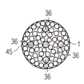
Figure 13 schematically shows another modification of rove bundle of the present invention with the form of cutaway view.
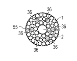
Figure 14 schematically shows the another modification of rove bundle of the present invention with the form of cutaway view.
The specific embodiment
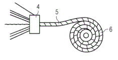
Referring now to Fig. 1-6 first embodiment of the present invention is described.Fig. 1 schematically shows the method that the present invention makes the rove wire harness.Many textured yarns 1 and a center resin flow yarn 2 are set up in the rove bundle 5 through winding apparatus 4.Extra winding yarn 3 is reeled along circumference around rove bundle 5 through winding apparatus 4.
The flow yarn 2 that the center is provided with for example can be porous yarn or fiber yarn.Preferably be placed on the centre of rove bundle 5.The center yarn is as the rapid resin transmission channels, so that reach the quick dipping of rove fiber 1.Through vacuum and capillary force, resin can move to yarn on every side from the center.Because the porous yarn centers, so equidistance is arranged with the outermost fiber 1 of restrainting 5.The osmos tube of plastic material, paper or other material can replace the porous yarn to use.
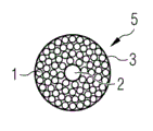
Fig. 2 schematically shows rove wire harness of the present invention with the form of cutaway view.Bundle 5 has round-shaped.Resin transmit yarn or manage 2 be positioned at bundle 5 the center, center on by many unidirectional rove 1.
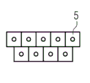
Fig. 3 schematically shows and for example is in the assembly that the rove bundle 5 by many basic inventions in the mould constitutes, to make the workpiece of similar wind turbine rotor blade.Fig. 3 shows bundle 5 with the form of cutaway view.Between the bundle that contacts with each other 5, there is air void 7.
Fig. 4 schematically shows during vacuum applies the process of current transfer modling technology, the assembly of the Fig. 3 after applying vacuum.In Fig. 4, rove bundle 5 becomes consolidation through for example in the close die system, applying vacuum.No longer there is air void 7 between the bundle 5.
Fig. 5 schematically shows the rove wire harness of the present invention of coiled plate-like.Through with before combine after winding apparatus 4 that Fig. 1 describes makes rove bundles 5, with the yarn beam 5 coiled plate-likes of twining.The coiling bundle is by Reference numeral 6 expressions.If use and elastically wrap yarn 3, the coiling of rove wire harness 5 then of the present invention is especially feasible.
Fig. 6 schematically shows the placement of rove bundle 5 of the present invention in mould 8.In Fig. 6, show the mould 8 that is used to make wind turbine rotor blade.In mould, set up many winding rove bundles 5 as describing before.Preferably, twine rove bundle 5 with longitudinal direction or with parallel establishment of span direction of wind turbine rotor blade.
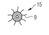
Another modification of winding rove bundle of the present invention is described referring now to Fig. 7-9.Fig. 7 schematically shows winding rove bundle 15 with the form of cutaway view.Fig. 8 schematically shows winding rove bundle 15 with the form of side view, and Fig. 9 schematically shows winding rove bundle 15 with the form of perspective view.
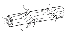
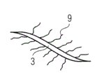
Referring now to Figure 10 and Figure 11 a modification that can be applicable to all embodiment of the present invention is described.The weak point of random orientation or long fibre can combine or be arranged in the winding yarn 3, and winding yarn 3 keeps together rove bundle 5 or 15.This is schematically shown in Figure 10 and Figure 11.Figure 10 schematically shows winding bundle 25 of the present invention with the form of perspective view.Figure 11 only schematically shows the winding yarn 3 of Figure 10.
The character of the bundle of in Fig. 1 and Fig. 2, describing before bundle 25 can have 5, the character of the bundle of describing with reference to Fig. 7-Fig. 9 before perhaps can having 15.Bundle 25 among Figure 10 comprises winding yarn 3, and winding yarn comprises laterally or the fiber 9 of random orientation.Fiber 9 horizontal or random orientation for example can be milled fibre, square fiber or long fibre, and this has improved the shear strength of the stacking material that will produce.And fiber 9 horizontal or random orientation can improve the cracking resistance system of formed fibre lay-up material.
Referring now to Figure 12-14 another embodiment of the present invention is described.Figure 12 schematically shows rove bundle 35 of the present invention with the form of cutaway view.Bundle comprises many textured yarns 1 and a thermoplastic fibre 36.Thermoplastic fibre 36 is positioned at the center of bundle 35.
Figure 13 schematically shows another modification of rove bundle 45 of the present invention with the form of cutaway view.Bundle 45 comprises many textured yarns 1 and Duo Gen thermoplastic fibre 36.In bundle 35, thermoplastic fibre 36 is arranged between the textured yarn 1 at random.
Figure 14 schematically shows another modification of rove bundle 55 of the present invention with the form of cutaway view.Rove bundle 55 comprises many textured yarns 1, and many thermoplastic fibres 36 and a resin transmit yarn 2.Resin transmission yarn 2 or resin distributing device 2 are placed on the center of bundle 55.The character of describing before resin distributing device 2 can have.Thermoplastic fibre 36 is arranged between the textured yarn 1 at random.
The method of manufacturing rove wire harness of the present invention also can be used for the fortifying fibre 1 and the mixture of the thermoplastic fibre shown in Figure 12-14 36, thermal plasticity slice or thermoplastic for example roughly.In order to make workpiece, for example wind turbine rotor blade can be put into the bundle of the present invention shown in Figure 12-14 35,45 and 55 in the mould.Thermoplastic fiber materials 36 mixes with reinforcing fiber materials 1, melts then and solidifies.For molten thermoplastic material, the thermoplastic fibre that can mix with fortifying fibre is heated to for example 200 ℃.Then, the liquid thermoplastic material can for example flow between fortifying fibre under the vacuum.After cooling, solidifying, workpiece is made into.
Except thermosetting material, liquid resin can be circulated into the close die system filling in the mould cavity of fiber.
All rove bundles 5,15,25,35,45 and 55 of before describing can be used for making workpiece, for example wind turbine rotor blade through vacuum-assisted resin transfer moulding technology (VARTM).Under this background, fibrous material, the rove bundle 5,15,25,35,45 and 55 of for example a plurality of unidirectional fiber layers and/or many basic inventions is placed in the mold shell.The mould heart can be put on the fibrous material.Then, but close die, and the closed mould cavity of picture applies vacuum.Then, resin can be injected in the mould cavity space between the fiber of packed layer laminate materials such as polyester, epoxy resin, vinyl ester resin or other resin.
Substituting ground or extraly, thermoplastic can mix with fibre reinforced materials perhaps can be arranged between the fibrage.In the case, thermoplastic can be heated, melt.Then, the mixture between thermoplastic fibre and the reinforcing fiber materials is by fixed, this is through initial heating and molten thermoplastic material, is cured realization through coolant then.Then, the mixture between thermoplastic fibre and the reinforcing fiber materials forms rigid composite material.
Claims (15)
1. method of making the bundle (5) of textured yarn (1),
It is characterized in that:
In bundle (5), set up many vertical unidirectional fibre textured yarns (1) and annexing ingredient (2,36).
2. method according to claim 1,
It is characterized in that:
At least one resin distributing device (2) or thermoplastic (36) are set as said annexing ingredient (2,36) in said bundle (5).
3. method according to claim 2,
It is characterized in that:
At least one porous yarn and/or fiber yarn and/or osmos tube and/or resin flow channel are set as resin distributing device (2) in said bundle (5), and/or at least one thermoplastic fibre and/or thermal plasticity slice are set in said bundle (5) as thermoplastic (36).
4. according to each described method among the claim 1-3,
It is characterized in that:
With glass fibre, carbon fiber, basalt fibre, aramid fiber or natural fiber as textured yarn (1).
5. according to each described method among the claim 1-4,
It is characterized in that:
Through winding yarn (3) rove wire harness (5) is twined.
6. according to each described method among the claim 1-5,
It is characterized in that:
Use comprises the textured yarn (1) of randomly oriented fiber or transverse fiber (9), and/or uses the winding yarn (3) that comprises randomly oriented fiber or transverse fiber (9).
7. a rove wire harness (5) comprises many vertical unidirectional fibre textured yarns (1) and annexing ingredient (2,36).
8. rove wire harness according to claim 7 (5),
It is characterized in that:
It comprises that at least one resin distributing device (2) or thermoplastic (36) are as said annexing ingredient.
9. rove wire harness according to claim 8 (5),
It is characterized in that:
It comprises at least one porous yarn and/or fiber yarn and/or osmos tube and/or resin flow channel as resin distributing device (2), and/or it comprises that at least one thermoplastic fibre and/or thermal plasticity slice are as thermoplastic (36).
10. according to each described rove wire harness (5) among the claim 7-9,
It is characterized in that:
It comprises at least one winding yarn (3).
11. according to each described rove wire harness (5) among the claim 7-10,
It is characterized in that:
Said textured yarn (1) comprises randomly oriented fiber or transverse fiber (9), and/or said winding yarn (3) comprises randomly oriented fiber or transverse fiber (9).
12. method of making workpiece through the vacuum-assisted resin transfer moulding technology; Comprise step: in the mould (8) of close die system, be provided with at least one like each described rove wire harness (5) of claim 7-11; Apply vacuum to said close die system, and resin is injected in the mould cavity.
13. method according to claim 12,
It is characterized in that compressing at least one rove wire harness (5) through vacuum.
14. a method of making workpiece comprises step:
In mould (8), be provided with like each described at least one rove wire harness (5) of claim 7-11, said rove wire harness comprises thermoplastic; And
Through at first heating and molten thermoplastic material, it is fixed then material cooled to be carried out.
15. a workpiece, it is by each described method manufacturing among the claim 12-14.
Applications Claiming Priority (2)
| Application Number | Priority Date | Filing Date | Title |
|---|---|---|---|
| EP11162812.9A EP2514584B1 (en) | 2011-04-18 | 2011-04-18 | Bundle of roving yarns, method of manufacturing a bundle of roving yarns and method for manufacturing a work piece |
| EP11162812.9 | 2011-04-18 |
Publications (1)
| Publication Number | Publication Date |
|---|---|
| CN102744891A true CN102744891A (en) | 2012-10-24 |
Family
ID=44653699
Family Applications (1)
| Application Number | Title | Priority Date | Filing Date |
|---|---|---|---|
| CN2012101140594A Pending CN102744891A (en) | 2011-04-18 | 2012-04-18 | Bundle of roving yarns, method of manufacturing a bundle of roving yarns and method for manufacturing a work piece |
Country Status (7)
| Country | Link |
|---|---|
| US (1) | US20120261854A1 (en) |
| EP (1) | EP2514584B1 (en) |
| JP (2) | JP6016428B2 (en) |
| KR (1) | KR20120118430A (en) |
| CN (1) | CN102744891A (en) |
| BR (1) | BR102012009052A2 (en) |
| IN (1) | IN2012DE00787A (en) |
Cited By (3)
| Publication number | Priority date | Publication date | Assignee | Title |
|---|---|---|---|---|
| CN105751522A (en) * | 2016-04-20 | 2016-07-13 | 华南理工大学 | Preparation device and method of long-fiber-reinforced thermoplastic resin composite material |
| CN111405971A (en) * | 2017-12-14 | 2020-07-10 | 巴斯夫欧洲公司 | Device and method for impregnating individual fibers, individual threads or individual rovings |
| CN114008256A (en) * | 2019-05-01 | 2022-02-01 | Pda生态创新实验室 | Rovings and fabrics for fiber reinforced composites |
Families Citing this family (4)
| Publication number | Priority date | Publication date | Assignee | Title |
|---|---|---|---|---|
| DE102013101188A1 (en) * | 2013-02-07 | 2014-08-07 | Rehau Ag + Co | Process for producing a PVC long-fiber thermoplastic |
| WO2014122157A1 (en) * | 2013-02-07 | 2014-08-14 | Lm Wp Patent Holding A/S | Limp, elongate element with glass staple fibres |
| DE102014015804A1 (en) * | 2014-10-24 | 2016-04-28 | Mt Aerospace Ag | Increasing the impregnability of dry fiber preforms |
| EP3837109B1 (en) * | 2018-10-04 | 2023-07-19 | B Preg Kompozit Ve Tekstil Muhendislik Danismanlik Sanayi Ticaret Anonim Sirketi | Semi -finished composite materials containing natural fibers and production thereof |
Citations (5)
| Publication number | Priority date | Publication date | Assignee | Title |
|---|---|---|---|---|
| JPS564727A (en) * | 1979-06-20 | 1981-01-19 | Toray Industries | Crude yarn and production thereof |
| EP0602618A1 (en) * | 1992-12-18 | 1994-06-22 | Hoechst Celanese Corporation | Process for preparing engineered fibre blend |
| US6454251B1 (en) * | 2000-05-01 | 2002-09-24 | John C. Fish | Composite cord assembly |
| CN101680226A (en) * | 2007-04-23 | 2010-03-24 | 兰德尔·布兰德斯特伦 | Fiber reinforced rebar |
| WO2010060913A1 (en) * | 2008-11-25 | 2010-06-03 | Nv Bekaert Sa | New metal fiber yarn with enhanced strength and processability |
Family Cites Families (19)
| Publication number | Priority date | Publication date | Assignee | Title |
|---|---|---|---|---|
| US4741873A (en) * | 1986-04-15 | 1988-05-03 | Kaiser Aerotech, A Division Of Sowa & Sons | Method for forming rigid composite preforms |
| JPH02139438A (en) * | 1988-11-21 | 1990-05-29 | Asahi Chem Ind Co Ltd | Continuous filament bundle reinforced by mixing stable fibers |
| JPH02210036A (en) * | 1989-02-09 | 1990-08-21 | Gunze Ltd | Conjugated yarn for reinforcement |
| US5052906A (en) * | 1989-03-30 | 1991-10-01 | Seemann Composite Systems, Inc. | Plastic transfer molding apparatus for the production of fiber reinforced plastic structures |
| JPH02269826A (en) * | 1989-04-11 | 1990-11-05 | Toyobo Co Ltd | Precursor for blend forming and production thereof |
| US5904972A (en) * | 1995-06-07 | 1999-05-18 | Tpi Technology Inc. | Large composite core structures formed by vacuum assisted resin transfer molding |
| US20050152139A1 (en) * | 1996-10-22 | 2005-07-14 | Loving David S. | Process for making lighted fiberglass panels |
| US6828016B2 (en) * | 1999-04-08 | 2004-12-07 | Mitsubishi Rayon Co., Ltd. | Preform for composite material and composite material |
| JP5055728B2 (en) * | 2004-09-10 | 2012-10-24 | 東レ株式会社 | Rod-shaped preshaped object and method for producing the same |
| US20070057404A1 (en) * | 2005-09-12 | 2007-03-15 | Hager William G | Compression and injection molding applications utilizing glass fiber bundles |
| EP1880833A1 (en) * | 2006-07-19 | 2008-01-23 | National University of Ireland, Galway | Composite articles comprising in-situ-polymerisable thermoplastic material and processes for their construction |
| GB0702781D0 (en) * | 2007-02-13 | 2007-03-21 | Airbus Uk Ltd | Method of processing a composite material |
| EP2221413B1 (en) * | 2007-11-15 | 2017-04-05 | Nippon Sheet Glass Company, Limited | Reinforcing cord and rubber product using the same |
| US20100286343A1 (en) * | 2008-01-08 | 2010-11-11 | Thomas Burghardt | Surfaces containing coupling activator compounds and reinforced composites produced therefrom |
| JP5315713B2 (en) * | 2008-02-12 | 2013-10-16 | 東レ株式会社 | Method for manufacturing preform for FRP member |
| WO2009131149A1 (en) * | 2008-04-24 | 2009-10-29 | 倉敷紡績株式会社 | Composite yarn and intermediate for fiber-reinforced resin and molded fiber-reinforced resin obtained therefrom |
| DE102008055771C5 (en) * | 2008-11-04 | 2018-06-14 | Senvion Gmbh | Rotorblattgurt |
| FR2948692B1 (en) * | 2009-07-28 | 2014-04-04 | Saertex France | USE OF A REINFORCING AND DRAINING WIRE |
| JP2011032987A (en) * | 2009-08-05 | 2011-02-17 | Nitto Denko Corp | Reinforcing sheet for wind turbine generator blade, reinforcing structure of wind turbine generator blade, wind turbine generator, and method of reinforcing wind turbine generator blade |
-
2011
- 2011-04-18 EP EP11162812.9A patent/EP2514584B1/en not_active Not-in-force
-
2012
- 2012-03-19 IN IN787DE2012 patent/IN2012DE00787A/en unknown
- 2012-04-16 US US13/447,390 patent/US20120261854A1/en not_active Abandoned
- 2012-04-17 BR BRBR102012009052-0A patent/BR102012009052A2/en not_active IP Right Cessation
- 2012-04-17 KR KR1020120039800A patent/KR20120118430A/en not_active Application Discontinuation
- 2012-04-17 JP JP2012094166A patent/JP6016428B2/en not_active Expired - Fee Related
- 2012-04-18 CN CN2012101140594A patent/CN102744891A/en active Pending
-
2016
- 2016-07-25 JP JP2016145720A patent/JP2016211139A/en not_active Ceased
Patent Citations (5)
| Publication number | Priority date | Publication date | Assignee | Title |
|---|---|---|---|---|
| JPS564727A (en) * | 1979-06-20 | 1981-01-19 | Toray Industries | Crude yarn and production thereof |
| EP0602618A1 (en) * | 1992-12-18 | 1994-06-22 | Hoechst Celanese Corporation | Process for preparing engineered fibre blend |
| US6454251B1 (en) * | 2000-05-01 | 2002-09-24 | John C. Fish | Composite cord assembly |
| CN101680226A (en) * | 2007-04-23 | 2010-03-24 | 兰德尔·布兰德斯特伦 | Fiber reinforced rebar |
| WO2010060913A1 (en) * | 2008-11-25 | 2010-06-03 | Nv Bekaert Sa | New metal fiber yarn with enhanced strength and processability |
Cited By (6)
| Publication number | Priority date | Publication date | Assignee | Title |
|---|---|---|---|---|
| CN105751522A (en) * | 2016-04-20 | 2016-07-13 | 华南理工大学 | Preparation device and method of long-fiber-reinforced thermoplastic resin composite material |
| CN105751522B (en) * | 2016-04-20 | 2018-06-29 | 华南理工大学 | A kind of preparation facilities and method of fiber reinforced thermoplastic resin composite material |
| CN111405971A (en) * | 2017-12-14 | 2020-07-10 | 巴斯夫欧洲公司 | Device and method for impregnating individual fibers, individual threads or individual rovings |
| CN111405971B (en) * | 2017-12-14 | 2023-05-16 | 巴斯夫欧洲公司 | Device and method for impregnating individual fibers, individual threads or individual rovings |
| CN114008256A (en) * | 2019-05-01 | 2022-02-01 | Pda生态创新实验室 | Rovings and fabrics for fiber reinforced composites |
| CN114008256B (en) * | 2019-05-01 | 2024-03-22 | Pda生态创新实验室 | Roving and fabric for fiber reinforced composites |
Also Published As
| Publication number | Publication date |
|---|---|
| US20120261854A1 (en) | 2012-10-18 |
| KR20120118430A (en) | 2012-10-26 |
| EP2514584A1 (en) | 2012-10-24 |
| BR102012009052A2 (en) | 2013-07-02 |
| JP2012224974A (en) | 2012-11-15 |
| JP6016428B2 (en) | 2016-10-26 |
| EP2514584B1 (en) | 2018-01-31 |
| IN2012DE00787A (en) | 2015-08-21 |
| JP2016211139A (en) | 2016-12-15 |
Similar Documents
| Publication | Publication Date | Title |
|---|---|---|
| CN102744891A (en) | Bundle of roving yarns, method of manufacturing a bundle of roving yarns and method for manufacturing a work piece | |
| CN102700153B (en) | Continuous pultrusion manufacturing method and production device for fibrous composite drive shaft | |
| JP2012016948A (en) | Method for manufacturing component of composite structure | |
| JP6138045B2 (en) | Method for producing high-weight carbon fiber sheet for RTM method and RTM method | |
| CN105682905B (en) | The proximate matter of the continuous manufacture and rigid foam filling of the proximate matter of sandwich structural type with foam core | |
| EP2729296B1 (en) | Wind turbine blade comprising metal filaments and carbon fibres and a method of manufacturing thereof | |
| TWI703030B (en) | Process for the continuous production of fibre-reinforced profiles comprising a foam core | |
| EP2874803B1 (en) | A stitched unidirectional or multi-axial reinforcement and a method of producing the same | |
| EP2874802B1 (en) | A unidirectional reinforcement and a method of producing a unidirectional reinforcement | |
| CN106891549A (en) | A kind of preparation facilities of MULTILAYER COMPOSITE eccentric abrasion prevention coiled rod | |
| EP2610053B1 (en) | Sandwich Core Material | |
| CN104908331B (en) | Fiber reinforced composites, components and methods | |
| CN104755253A (en) | Method & apparatus for making a composite structure | |
| CN111720631A (en) | High-ring-stiffness stretch-wound FRP pipe and preparation method thereof | |
| CN209440832U (en) | A kind of fibre reinforced composites twine pressing molding device | |
| JP2016527112A (en) | Composite form manufacturing method, composite form, sandwich component, rotor blade element, and wind power generator | |
| CN114131981A (en) | Method for manufacturing steel bar body | |
| JP6278488B2 (en) | VaRTM reinforcing fiber sheet | |
| KR100580226B1 (en) | fiber reinforced polymer pipe forming equipment for grouting and its manufacture method | |
| CN105437563B (en) | Polymeric nanoparticles for controlling permeability and fiber volume fraction in composites | |
| CN104325653A (en) | Continuous glass steel pipeline manufacturing method and prepared glass steel pipeline | |
| CN115464905A (en) | Weaving method for improving shear strength of FRP (fiber reinforced plastic) bar | |
| JP6061568B2 (en) | Method for producing reinforced fiber sheet for VaRTM and method for molding fiber reinforced plastic structure | |
| KR102168785B1 (en) | One-row pultrusion apparatus | |
| CN104943192A (en) | Anti-static fiber reinforced plastic pipeline and continuous manufacturing method thereof |
Legal Events
| Date | Code | Title | Description |
|---|---|---|---|
| C06 | Publication | ||
| PB01 | Publication | ||
| C10 | Entry into substantive examination | ||
| SE01 | Entry into force of request for substantive examination | ||
| AD01 | Patent right deemed abandoned |
Effective date of abandoning: 20180403 |
|
| AD01 | Patent right deemed abandoned |
