The special-purpose anchor ear frock of offshore wind turbine complete engine set installation
Technical field
The present invention relates to the accessory equipment that a kind of blower fan is installed, particularly relate to the special-purpose anchor ear frock of a kind of offshore wind turbine complete engine set installation.
Background technology
Present stage, the normal mode that adopts the blower fan integral installation in the marine wind electric field process of construction of China, this mode great advantage is to reduce the marine operation time, reduces the non-controllable risk that natural conditions caused.Offshore wind turbine integral type mounting means often adopts large-scale crane ship to carry out complete blower and installs; The blower fan that it used is installed special tooling and mainly is made up of top equalizing bar and bottom steel carriage; The top equalizing bar is positioned at more than the complete blower center of gravity; The bottom steel carriage is positioned at the blower fan tower barrel bottom, and the vertical bearing force of complete blower is provided.If adopt aforementioned mounting means, need to use large-scale marine crane ship, because that the machine-team of large-scale crane ship takes is higher, thereby can improve the cost of installation of blower fan greatly, and this problem is not resolved as yet at present.
Summary of the invention
Based on this; To the problems referred to above; The present invention proposes the special-purpose anchor ear frock of a kind of offshore wind turbine complete engine set installation; Combine promptly to can be used for the offshore wind turbine complete engine set installation with professional mounting ship of offshore wind turbine, need not use large-scale marine crane ship to be used for the complete blower installation, thereby significantly reduce the cost of installation of blower fan.
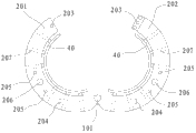
Technical scheme of the present invention is: the special-purpose anchor ear frock of a kind of offshore wind turbine complete engine set installation; Comprise the anchor ear carriage, be located at the anchor ear on the anchor ear carriage and rotate the anchor ear hydraulically extensible bar that propulsive effort is provided for anchor ear; Said anchor ear was made up of left anchor ear plate that all is semi-annular shape and right involutory connection of anchor ear plate; One end of said left anchor ear plate and an end of said right anchor ear plate are hinged; The other end of the other end of said left anchor ear plate and said right anchor ear plate is provided with the anchor ear locking pin-and-hole that cooperatively interacts; The outer toroid edge of said left anchor ear plate and said right anchor ear plate is an end of hinged one said anchor ear hydraulically extensible bar respectively, and the other end of this anchor ear hydraulically extensible bar is articulated on the said anchor ear carriage.
The special-purpose anchor ear frock of the described offshore wind turbine complete engine set installation of present technique scheme;, complete blower can be positioned at below the blower fan center of gravity when installing; It is used in combination with professional mounting ship of offshore wind turbine and can reduces the lifting requirement for height of complete blower installation to the special fan mounting shipping greatly; Avoid the use of large-scale crane ship and be used for the complete blower installation, thereby reduce the blower fan erected cost.The main effect of anchor ear is that the folding through left anchor ear plate and right anchor ear plate grips blower fan tower barrel, and through the anchor ear hydraulic pressure strut length of regulating in left anchor ear plate and the right anchor ear plate certain Clamping force is provided, and guarantees its stable equilibrium.The main effect of anchor ear carriage is for anchor ear provides support, and the anchor ear carriage can link to each other with the steel framework on special-purpose mounting ship of offshore wind turbine top and be formed into complete equipment and be used for the offshore wind turbine complete engine set installation.The apparent size of anchor ear carriage is mainly determined by two aspects: the one, and the opening size of anchor ear carriage should be able to satisfy anchor ear all can work under the folding two states; The 2nd, can satisfy the structure stress demand of anchor ear and anchor ear carriage self.
Among embodiment, on said anchor ear carriage, be provided with anchor ear rotating spindle therein as left anchor ear plate and right anchor ear plate hinge axis.Purpose is that the hinged support with anchor ear is arranged on the anchor ear carriage, and it is more steady that whole frock is moved.
Therein among embodiment; Be equipped with anchor ear rail wheel, limit pin hole and lifting lifting hole(eyelet) on said left anchor ear plate and the said right anchor ear plate; Be provided with the anchor ear sliding rail that cooperates with the anchor ear rail wheel and reserve lifting hole(eyelet) at the correspondence position of said anchor ear carriage, on said anchor ear carriage, also be provided with and the cooresponding a plurality of spacing holes of said limit pin hole path of motion with the arc lifting of lifting lifting hole(eyelet) path of motion coupling.Purpose is to guarantee that left anchor ear plate and right anchor ear plate in the process of folding, can have the structure of assist location and tracks positioned, more further makes the operation of whole frock more steady.
Among embodiment, the interior ring surface of said left anchor ear plate and said right anchor ear plate is equipped with the anchor ear interior lining panel therein.Purpose is to make anchor ear interior lining panel and blower fan tower barrel direct contact, through regulating the length of anchor ear hydraulic pressure strut, adapts to the blower fan tower barrel of different-diameter, also can more firmly grasp whole blower fan tower barrel simultaneously.
Among embodiment, be provided with anchor ear hydraulic pressure strut at said left anchor ear plate along its circumferencial direction therein, this anchor ear hydraulic pressure strut one end is connected on the said anchor ear interior lining panel, and the other end extends to said left anchor ear plate outer shroud place.Be designed with two purposes like this, the firstth, can adapt to the type of all kinds of different tower tube diameters, the secondth, the reducing problem of tower tube in the time of adapting to blower fan and install provides the huge Clamping force of clamping blower fan tower barrel simultaneously.
Among embodiment, be provided with anchor ear hydraulic pressure strut at said right anchor ear plate along its circumferencial direction therein, this anchor ear hydraulic pressure strut one end is connected on the said anchor ear interior lining panel, and the other end extends to said right anchor ear plate outer shroud place.Be designed with two purposes like this, the firstth, can adapt to the type of all kinds of different tower tube diameters, the secondth, the reducing problem of tower tube in the time of adapting to blower fan and install provides the huge Clamping force of clamping blower fan tower barrel simultaneously.
Among embodiment, the junction of said anchor ear interior lining panel and said anchor ear hydraulic pressure strut is provided with pressure sensor therein, and this pressure sensor is connected in the monitored control system of peripheral hardware.Purpose is to be convenient to detect the pressure between anchor ear interior lining panel and the anchor ear hydraulic pressure strut, so that situation and each parameter of the whole frock operation of artificial judgment and grasp.Monitored control system is mainly used in monitoring frock mode of operation when work, and monitored control system mainly is provided with facilities such as illumination, video monitoring, the monitoring of anchor ear pressure sensing.
Therein among embodiment, be provided with hoisting winding in the bilateral symmetry of said anchor ear carriage.Be mainly used in the lifting power when providing blower fan to install when complete blower is installed, the control of hoisting winding is born by control system.The main effect of control system is control anchor ear hydraulically extensible bar, hoisting winding and all kinds of locating dowel pin liftings etc., and it can link to each other with the centralized control room that professional blower fan is installed on the ship.
Among embodiment, the inside of said left anchor ear plate and said right anchor ear plate is trussed steel beam therein, and the outside is a steel plate.Purpose is to make left anchor ear plate and right anchor ear plate can have enough rigidity.
The invention has the beneficial effects as follows: the steel framework of installing on the ship through anchor ear framework and special fan links to each other; In the time of can reducing complete blower greatly and install to the lifting requirement for height of weight-lifting equipment; Avoid the use of large-scale crane ship and be used for the complete blower installation, thereby practice thrift the offshore wind turbine erected cost.
Description of drawings
Fig. 1 is the frock birds-eye view of embodiment of the invention anchor ear closure state;
Fig. 2 is along the structural representation of A-A to observation among Fig. 1;
Fig. 3 is the frock birds-eye view of embodiment of the invention anchor ear open mode;
Fig. 4 is along the structural representation of B-B to observation among Fig. 3;
Fig. 5 is the structural representation of embodiment of the invention anchor ear carriage;
Fig. 6 is an anchor ear of the present invention structural representation when closed;
Fig. 7 is the structural representation of anchor ear of the present invention when opening;
Description of reference numerals:
10-anchor ear carriage, 101-anchor ear rotating spindle, 102-anchor ear sliding rail, lifting hole(eyelet) is reserved in the 103-lifting; 104-spacing hole, 201-left side anchor ear plate, the right anchor ear plate of 202-, 203-anchor ear locking pin-and-hole; 204-anchor ear rail wheel, 205-limit pin hole, 206-lifting lifting hole(eyelet), 207-anchor ear hydraulic pressure strut; 30-anchor ear hydraulically extensible bar, 40-anchor ear interior lining panel, 50-hoisting winding.
The specific embodiment
Below in conjunction with accompanying drawing embodiments of the invention are elaborated.
Embodiment:
To shown in Figure 7, the special-purpose anchor ear frock of a kind of offshore wind turbine complete engine set installation comprises anchor ear carriage 10, is located at the anchor ear on the anchor ear carriage 10 and the anchor ear hydraulically extensible bar 30 of propulsive effort is provided for the anchor ear rotation like Fig. 1.Said anchor ear was made up of left anchor ear plate 201 that all is semi-annular shape and right 202 involutory connections of anchor ear plate; One end of said left anchor ear plate 201 and an end of said right anchor ear plate 202 are hinged, and the other end of the other end of said left anchor ear plate 201 and said right anchor ear plate 202 is provided with the anchor ear locking pin-and-hole 203 that cooperatively interacts.The outer toroid edge of said left anchor ear plate 201 and said right anchor ear plate 202 is an end of hinged one said anchor ear hydraulically extensible bar 30 respectively, and the other end of this anchor ear hydraulically extensible bar 30 is articulated on the said anchor ear carriage 10.
In the present embodiment, on said anchor ear carriage 10, be provided with as the anchor ear rotating spindle 101 of left anchor ear plate 201 with right anchor ear plate 202 hinge axis.Purpose is that the hinged support with anchor ear is arranged on the anchor ear carriage 10, and it is more steady that whole frock is moved.
In the present embodiment; Be equipped with anchor ear rail wheel 204, limit pin hole 205 and lifting lifting hole(eyelet) 206 on said left anchor ear plate 201 and the said right anchor ear plate 202; Correspondence position at said anchor ear carriage 10 is provided with the anchor ear sliding rail 102 of the circular arc that cooperates with anchor ear rail wheel 204 and reserves lifting hole(eyelet) 103 with the arc lifting of lifting lifting hole(eyelet) 206 path of motions coupling; On said anchor ear carriage 10, also be provided with and cooresponding four spacing holes 104 of said limit pin hole 205 path of motions, also can confirm the quantity of spacing hole 104 according to actual conditions.Purpose is to guarantee that left anchor ear plate 201 and right anchor ear plate 202 in the process of folding, can have the structure of assist location and tracks positioned, more further makes the operation of whole frock more steady.
In the present embodiment, said left anchor ear plate 201 is equipped with anchor ear interior lining panel 40 with the interior ring surface of said right anchor ear plate 202.Purpose is to make anchor ear interior lining panel 40 and blower fan tower barrel direct contact, through regulating the length of anchor ear hydraulic pressure strut 207, adapts to the blower fan tower barrel of different-diameter, also can more firmly grasp whole blower fan simultaneously.
In the present embodiment, be provided with many anchor ear hydraulic pressure struts 207 at said left anchor ear plate 201 along its circumferencial direction, every anchor ear hydraulic pressure strut 207 1 ends are connected on the said anchor ear interior lining panel 40, and the other end extends to said left anchor ear plate 201 outer shroud places.Be designed with two purposes like this, the firstth, can adapt to the type of all kinds of different tower tube diameters, the secondth, the reducing problem of tower tube in the time of adapting to blower fan and install provides the huge Clamping force of clamping blower fan tower barrel simultaneously.
In the present embodiment, be provided with many anchor ear hydraulic pressure struts 207 at said right anchor ear plate 202 along its circumferencial direction, every anchor ear hydraulic pressure strut 207 1 ends are connected on the said anchor ear interior lining panel 40, and the other end extends to said right anchor ear plate 202 outer shroud places.Be designed with two purposes like this, the firstth, can adapt to the type of all kinds of different tower tube diameters, the secondth, the reducing problem of tower tube in the time of adapting to blower fan and install provides the huge Clamping force of clamping blower fan tower barrel simultaneously.
In the present embodiment, said anchor ear interior lining panel 40 is provided with the pressure sensor (not shown) with the junction of said anchor ear hydraulic pressure strut 207, and this pressure sensor is connected in the monitored control system of peripheral hardware.Purpose is to be convenient to detect the pressure between anchor ear interior lining panel 40 and the anchor ear hydraulic pressure strut 207, so that situation and each parameter of the whole frock operation of artificial judgment and grasp.Monitored control system is mainly used in monitoring frock mode of operation when work, and monitored control system mainly is provided with facilities such as illumination, video monitoring, the monitoring of anchor ear pressure sensing.
In the present embodiment, be provided with hoisting winding 50 in the bilateral symmetry of said anchor ear carriage 10.Be mainly used in the lifting power when providing blower fan to install when complete blower is installed, the control of hoisting winding 50 is born by control system.The main effect of control system is control anchor ear hydraulically extensible bar 30, hoisting winding 50 and all kinds of locating dowel pin liftings etc., and it can link to each other with the centralized control room that professional blower fan is installed on the ship.
In the present embodiment, said left anchor ear plate 201 is a trussed steel beam with the inside of said right anchor ear plate 202, and the outside is a steel plate.Purpose is to make left anchor ear plate 201 can have enough rigidity with right anchor ear plate 202.
The special-purpose anchor ear frock of offshore wind turbine complete engine set installation of the present invention;, complete blower can be positioned at below the blower fan center of gravity when installing; It is used in combination with professional mounting ship of offshore wind turbine and can reduces the lifting requirement for height of complete blower installation to the special fan mounting shipping greatly, thereby reduces the blower fan erected cost.The main effect of anchor ear is that the folding through left anchor ear plate 201 and right anchor ear plate 202 grips blower fan tower barrel, and through anchor ear hydraulic pressure strut 207 certain Clamping force is provided, and guarantees its stable equilibrium.The main effect of anchor ear carriage 10 is to provide support for anchor ear.Anchor ear carriage 10 can link to each other with the steel member on special-purpose mounting ship of offshore wind turbine top and be formed into complete equipment and be used for the offshore wind turbine complete engine set installation.The apparent size of anchor ear carriage 10 is mainly determined by two aspects: the one, and the opening size of anchor ear carriage 10 should be able to satisfy anchor ear all can work under the folding two states; The 2nd, can satisfy the structure stress demand of anchor ear and anchor ear carriage 10 self.
The above embodiment has only expressed the specific embodiment of the present invention, and it describes comparatively concrete and detailed, but can not therefore be interpreted as the restriction to claim of the present invention.Should be pointed out that for the person of ordinary skill of the art under the prerequisite that does not break away from the present invention's design, can also make some distortion and improvement, these all belong to protection scope of the present invention.