CN102656406A - Gasification system - Google Patents
Gasification system Download PDFInfo
- Publication number
- CN102656406A CN102656406A CN201080054988XA CN201080054988A CN102656406A CN 102656406 A CN102656406 A CN 102656406A CN 201080054988X A CN201080054988X A CN 201080054988XA CN 201080054988 A CN201080054988 A CN 201080054988A CN 102656406 A CN102656406 A CN 102656406A
- Authority
- CN
- China
- Prior art keywords
- combustion chamber
- synthesis gas
- gas
- process chamber
- chamber
- Prior art date
- Legal status (The legal status is an assumption and is not a legal conclusion. Google has not performed a legal analysis and makes no representation as to the accuracy of the status listed.)
- Pending
Links
Images


Classifications
-
- F—MECHANICAL ENGINEERING; LIGHTING; HEATING; WEAPONS; BLASTING
- F23—COMBUSTION APPARATUS; COMBUSTION PROCESSES
- F23G—CREMATION FURNACES; CONSUMING WASTE PRODUCTS BY COMBUSTION
- F23G5/00—Incineration of waste; Incinerator constructions; Details, accessories or control therefor
- F23G5/02—Incineration of waste; Incinerator constructions; Details, accessories or control therefor with pretreatment
- F23G5/027—Incineration of waste; Incinerator constructions; Details, accessories or control therefor with pretreatment pyrolising or gasifying stage
- F23G5/0273—Incineration of waste; Incinerator constructions; Details, accessories or control therefor with pretreatment pyrolising or gasifying stage using indirect heating
-
- B—PERFORMING OPERATIONS; TRANSPORTING
- B01—PHYSICAL OR CHEMICAL PROCESSES OR APPARATUS IN GENERAL
- B01J—CHEMICAL OR PHYSICAL PROCESSES, e.g. CATALYSIS OR COLLOID CHEMISTRY; THEIR RELEVANT APPARATUS
- B01J19/00—Chemical, physical or physico-chemical processes in general; Their relevant apparatus
- B01J19/08—Processes employing the direct application of electric or wave energy, or particle radiation; Apparatus therefor
- B01J19/12—Processes employing the direct application of electric or wave energy, or particle radiation; Apparatus therefor employing electromagnetic waves
- B01J19/122—Incoherent waves
- B01J19/127—Sunlight; Visible light
-
- B—PERFORMING OPERATIONS; TRANSPORTING
- B09—DISPOSAL OF SOLID WASTE; RECLAMATION OF CONTAMINATED SOIL
- B09B—DISPOSAL OF SOLID WASTE
- B09B3/00—Destroying solid waste or transforming solid waste into something useful or harmless
-
- C—CHEMISTRY; METALLURGY
- C10—PETROLEUM, GAS OR COKE INDUSTRIES; TECHNICAL GASES CONTAINING CARBON MONOXIDE; FUELS; LUBRICANTS; PEAT
- C10J—PRODUCTION OF PRODUCER GAS, WATER-GAS, SYNTHESIS GAS FROM SOLID CARBONACEOUS MATERIAL, OR MIXTURES CONTAINING THESE GASES; CARBURETTING AIR OR OTHER GASES
- C10J3/00—Production of combustible gases containing carbon monoxide from solid carbonaceous fuels
- C10J3/02—Fixed-bed gasification of lump fuel
- C10J3/20—Apparatus; Plants
-
- F—MECHANICAL ENGINEERING; LIGHTING; HEATING; WEAPONS; BLASTING
- F23—COMBUSTION APPARATUS; COMBUSTION PROCESSES
- F23G—CREMATION FURNACES; CONSUMING WASTE PRODUCTS BY COMBUSTION
- F23G5/00—Incineration of waste; Incinerator constructions; Details, accessories or control therefor
- F23G5/02—Incineration of waste; Incinerator constructions; Details, accessories or control therefor with pretreatment
- F23G5/027—Incineration of waste; Incinerator constructions; Details, accessories or control therefor with pretreatment pyrolising or gasifying stage
-
- F—MECHANICAL ENGINEERING; LIGHTING; HEATING; WEAPONS; BLASTING
- F23—COMBUSTION APPARATUS; COMBUSTION PROCESSES
- F23G—CREMATION FURNACES; CONSUMING WASTE PRODUCTS BY COMBUSTION
- F23G5/00—Incineration of waste; Incinerator constructions; Details, accessories or control therefor
- F23G5/08—Incineration of waste; Incinerator constructions; Details, accessories or control therefor having supplementary heating
- F23G5/14—Incineration of waste; Incinerator constructions; Details, accessories or control therefor having supplementary heating including secondary combustion
- F23G5/16—Incineration of waste; Incinerator constructions; Details, accessories or control therefor having supplementary heating including secondary combustion in a separate combustion chamber
-
- F—MECHANICAL ENGINEERING; LIGHTING; HEATING; WEAPONS; BLASTING
- F23—COMBUSTION APPARATUS; COMBUSTION PROCESSES
- F23G—CREMATION FURNACES; CONSUMING WASTE PRODUCTS BY COMBUSTION
- F23G7/00—Incinerators or other apparatus for consuming industrial waste, e.g. chemicals
-
- F—MECHANICAL ENGINEERING; LIGHTING; HEATING; WEAPONS; BLASTING
- F24—HEATING; RANGES; VENTILATING
- F24S—SOLAR HEAT COLLECTORS; SOLAR HEAT SYSTEMS
- F24S23/00—Arrangements for concentrating solar-rays for solar heat collectors
- F24S23/70—Arrangements for concentrating solar-rays for solar heat collectors with reflectors
- F24S23/71—Arrangements for concentrating solar-rays for solar heat collectors with reflectors with parabolic reflective surfaces
-
- F—MECHANICAL ENGINEERING; LIGHTING; HEATING; WEAPONS; BLASTING
- F24—HEATING; RANGES; VENTILATING
- F24S—SOLAR HEAT COLLECTORS; SOLAR HEAT SYSTEMS
- F24S23/00—Arrangements for concentrating solar-rays for solar heat collectors
- F24S23/70—Arrangements for concentrating solar-rays for solar heat collectors with reflectors
- F24S23/74—Arrangements for concentrating solar-rays for solar heat collectors with reflectors with trough-shaped or cylindro-parabolic reflective surfaces
-
- F—MECHANICAL ENGINEERING; LIGHTING; HEATING; WEAPONS; BLASTING
- F23—COMBUSTION APPARATUS; COMBUSTION PROCESSES
- F23G—CREMATION FURNACES; CONSUMING WASTE PRODUCTS BY COMBUSTION
- F23G2201/00—Pretreatment
- F23G2201/30—Pyrolysing
- F23G2201/303—Burning pyrogases
-
- F—MECHANICAL ENGINEERING; LIGHTING; HEATING; WEAPONS; BLASTING
- F23—COMBUSTION APPARATUS; COMBUSTION PROCESSES
- F23G—CREMATION FURNACES; CONSUMING WASTE PRODUCTS BY COMBUSTION
- F23G2202/00—Combustion
- F23G2202/10—Combustion in two or more stages
- F23G2202/103—Combustion in two or more stages in separate chambers
-
- F—MECHANICAL ENGINEERING; LIGHTING; HEATING; WEAPONS; BLASTING
- F23—COMBUSTION APPARATUS; COMBUSTION PROCESSES
- F23G—CREMATION FURNACES; CONSUMING WASTE PRODUCTS BY COMBUSTION
- F23G2209/00—Specific waste
-
- F—MECHANICAL ENGINEERING; LIGHTING; HEATING; WEAPONS; BLASTING
- F23—COMBUSTION APPARATUS; COMBUSTION PROCESSES
- F23G—CREMATION FURNACES; CONSUMING WASTE PRODUCTS BY COMBUSTION
- F23G2900/00—Special features of, or arrangements for incinerators
- F23G2900/50204—Waste pre-treatment by pyrolysis, gasification or cracking
-
- Y—GENERAL TAGGING OF NEW TECHNOLOGICAL DEVELOPMENTS; GENERAL TAGGING OF CROSS-SECTIONAL TECHNOLOGIES SPANNING OVER SEVERAL SECTIONS OF THE IPC; TECHNICAL SUBJECTS COVERED BY FORMER USPC CROSS-REFERENCE ART COLLECTIONS [XRACs] AND DIGESTS
- Y02—TECHNOLOGIES OR APPLICATIONS FOR MITIGATION OR ADAPTATION AGAINST CLIMATE CHANGE
- Y02E—REDUCTION OF GREENHOUSE GAS [GHG] EMISSIONS, RELATED TO ENERGY GENERATION, TRANSMISSION OR DISTRIBUTION
- Y02E10/00—Energy generation through renewable energy sources
- Y02E10/40—Solar thermal energy, e.g. solar towers
-
- Y—GENERAL TAGGING OF NEW TECHNOLOGICAL DEVELOPMENTS; GENERAL TAGGING OF CROSS-SECTIONAL TECHNOLOGIES SPANNING OVER SEVERAL SECTIONS OF THE IPC; TECHNICAL SUBJECTS COVERED BY FORMER USPC CROSS-REFERENCE ART COLLECTIONS [XRACs] AND DIGESTS
- Y02—TECHNOLOGIES OR APPLICATIONS FOR MITIGATION OR ADAPTATION AGAINST CLIMATE CHANGE
- Y02P—CLIMATE CHANGE MITIGATION TECHNOLOGIES IN THE PRODUCTION OR PROCESSING OF GOODS
- Y02P20/00—Technologies relating to chemical industry
- Y02P20/10—Process efficiency
- Y02P20/133—Renewable energy sources, e.g. sunlight
-
- Y—GENERAL TAGGING OF NEW TECHNOLOGICAL DEVELOPMENTS; GENERAL TAGGING OF CROSS-SECTIONAL TECHNOLOGIES SPANNING OVER SEVERAL SECTIONS OF THE IPC; TECHNICAL SUBJECTS COVERED BY FORMER USPC CROSS-REFERENCE ART COLLECTIONS [XRACs] AND DIGESTS
- Y02—TECHNOLOGIES OR APPLICATIONS FOR MITIGATION OR ADAPTATION AGAINST CLIMATE CHANGE
- Y02P—CLIMATE CHANGE MITIGATION TECHNOLOGIES IN THE PRODUCTION OR PROCESSING OF GOODS
- Y02P80/00—Climate change mitigation technologies for sector-wide applications
- Y02P80/20—Climate change mitigation technologies for sector-wide applications using renewable energy
Abstract
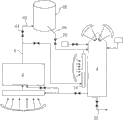
The invention provides an apparatus for processing material such as organically coated waste and organic materials including biomass, industrial waste, municipal solid waste and sludge, comprising a processing chamber (2) for processing said material at an elevated temperature to produce syngas and a combustion chamber (4) having at least one burner therein for combusting syngas released by processing of said material. A conduit means (18) is provided between said combustion chamber and said processing chamber for carrying hot exhaust gasses from the combustion chamber (4) to said processing chamber (2) and at last one mirror (24) is arranged to reflect and concentrate sunlight thereby to cause the temperature within said processing chamber (2) to be raised. The apparatus also includes a syngas reservoir (66). A storage conduit (62) is provided for carrying syngas into said syngas reservoir (66) and a syngas feed line (68) is provided for feeding syngas from said reservoir to said combustion chamber (4).
Description
Technical field
The present invention relates to gasification system, relate in particular to the gasification system that is used for waste material.
Background technology
The hot gasization of the waste product through pyrolytic under controlled condition is to be used for disperseing waste material and to be used for therefrom producing the known process of synthetic gas (synthesis gas), and it then can be used to the known method produce power.Therefore, can recover energy the organic matter in waste material.
A problem relevant with this processing provides the heat that is used for pyrolytic so that generally use neat gas burner to necessitate.Start-up system and waste material is increased to its high-temperature decomposition temperature and then waste material provided to the fixed combustion device of the synthesis gas that wherein can burn all need natural gas.
In the waste material gasification system, use natural gas to eliminate some environmental benefit that from the waste material organic matter, recover energy and can how much remedy any advantage that is obtained.
Summary of the invention
The object of the present invention is to provide a kind of improvement system that is used to handle organic waste materials.
According to a first aspect of the invention; Provide a kind of and be used to handle such as the equipment of organic coating waste material with the material of the organic material that comprises bio-waste, industrial waste, municipal solid waste material and mud, said equipment comprises: be used in anaerobic environment with the said material of Temperature Treatment that improves to produce the process chamber of synthesis gas; The combustion chamber that has at least one burner therein is used to burn through handling the synthesis gas that said material discharges; Plumbing installation between said combustion chamber and said process chamber is used for hot waste gas is transported to said process chamber from the combustion chamber; With, thereby be arranged to reflect and concentrated sunlight makes at least one mirror that temperature in the said process chamber is enhanced.
The present invention possibly also comprise: the synthesis gas reservoir; Be used for synthesis gas is transported to the storage pipeline of said synthesis gas reservoir; With, be used for synthesis gas is supplied to from said reservoir the synthesis gas supply pipeline of said combustion chamber.
Storage pipeline and supply pipeline are included in the multistage pipeline between said process chamber and the said combustion chamber, thereby make the synthesis gas reservoir be embedded in the said pipeline.Selectively; Reservoir can off-line location and storage pipeline and supply pipeline are connected to process chamber and combustion chamber respectively with reservoir; And can divide out branch from the pipeline between said process chamber and the said combustion chamber randomly; Correspondingly, synthesis gas reservoir bypass duct is provided for and makes gas not flow to the combustion chamber from process chamber under the situation through the synthesis gas reservoir.
Preferably, provide control gas to flow to first control valve the synthesis gas reservoir from process chamber; With, the control exhaust-gas flow gets into second valve of the combustion chamber of process chamber.
Therefore, equipment can be configured to unnecessary synthesis gas is directly introduced the storage reservoir.Have the some benefits that comprise the combustion chamber that provides littler like this.Therefore, when being used to the batch process of organic waste materials, the synthesis gas that is produced is not a current stabilization, but locates to spread downwards at the termination place that handles to vertical spread beginning of handling, and the size of combustion chamber must be designed to meet maximum demand.Through the synthesis gas reservoir is provided, some synthesis gas can be transferred to the synthesis gas reservoir, can balance the consumption of synthesis gas in the combustion chamber in the circulation.The further advantage of reservoir will detail below.
Correspondingly, equipment can also comprise: second mirror, thus be used for sunlight reflected was carried out preheating to the said synthesis gas through said bypass duct on second heat absorbing surface of contiguous said reservoir bypass duct before the burning of said combustion chamber.Through improving the temperature of synthesis gas before burning in the combustion chamber at synthesis gas, during burn processing, need external energy still less.In a preferred disposition, equipment comprises the combustion tower that covers said combustion chamber, and second heat absorbing surface comprises the outer surface of said combustion tower.
Preferably; According to each described equipment in the aforesaid right requirement, also comprise: to the fossil fuel supply pipeline of said burner, said fossil fuel supply pipeline can keep the burner fault-free; And/or; When lacking enough synthesis gas and/or solar energy, be provided for enough fossil fuel of in said burner, burning, thereby be the enough heat energy of generation of the oxidation of any synthesis gas of getting into said combustion chamber in use.
In a configuration, the present invention also comprises: relative at least one external heat sorbent surface, and said at least one mirror is configured to sunlight reflected and concentrates on the said heat absorption surface; Said heat absorption surface comprises that the outer and contiguous said heat absorption skin of heat absorption is used to receive the first gas water back of waste gas of combustion chamber; The said first gas water back is communicated with said process chamber fluid; Like this; In use, being close to waste gas of combustion chamber that said heat absorbing surface passes through is heated by the said sunlight that is reflected and flows in the said process chamber to improve temperature wherein.
Next be transported to the gas of process chamber through heating; Can obtain better control to the process chamber environment; Because can increase or reduce air-flow changing its time of staying in the first gas water back, thereby change the temperature of the said gas that gets into said process chamber.
Preferably, thus have the insulating barrier that the contiguous said first gas water back and said absorbed layer separate; With, can operate with direct exhaust from said combustion chamber through the said first gas water back or direct exhaust from said combustion chamber the bypass valve through the bypass of gas water back; Wherein, the bypass of said gas water back is separated through separation layer and said heat absorbing surface.
In this mode; When obtaining sunlight when adding heat absorbing surface; Waste gas from the combustion chamber can be heated through the first gas water back, and when perhaps minimum sunlight can not obtain, for example at night; Can bypass cross sorbent surface avoiding thermal losses wherein from the hot waste gas of combustion chamber, thereby guarantee to get into process chamber so that it is heated from the heat of the maximum of waste gas of combustion chamber.
In a preferred embodiment, the removable and heat absorbing surface of process chamber forms the outer surface of said removable process chamber.
The outer surface of first and/or second heat absorbing surface can have superficial makings (texture) above that to increase its surface area.Though in fixing configuration, have superiority; But has advantage more in the configuration below this; Wherein process chamber moves at run duration; For example rotation or pivot, thereby it makes the surface area maximization that is exposed to the sunlight that is reflected and reducing the motion with the tracking process chamber of the demand of mirror in any one time.Preferably, the inner surface of first and/or second heat absorbing surface has superficial makings (texture) above that so that pass through the air-flow turbulization on surface, thus the heat exchange of increase and said heat absorbing surface.
Equipment can also comprise the mirror that at least one is other, and this at least one other mirror is used for sunlight is directly reflected and focuses on said combustion chamber to improve said combustion chamber temperature.
Solar energy through being concentrated directly reflex in the combustion chamber, and solar energy can directly be used for the synthesis gas temperature is increased to required more than 850 °, and this temperature is essential for the synthesis gas burning to reduce harmful emission.The use that is used for the direct solar energy heating of this processing also has extra advantage, that is, being easier to when under the help of neat gas burner, adopting the synthesis gas burning to be used for provides two seconds required dwell period under the temperature that is enhanced of synthesis gas oxidation.Because natural gas and the interpolation that is used for the oxidant of gas-firing can increase the total measurement (volume) that burning gases are treated in the inboard, combustion chamber in the combustion chamber, so need bigger combustion chamber to hold and this extra volume that burns.Next, therefore, make the elimination of the natural gas that needs or minimize the volume that has reduced the combustion chamber of realizing that the required time of staying is essential at least.
Solar energy through being concentrated directly reflex in the combustion chamber, and solar energy can directly be used for the synthesis gas temperature is increased to required more than 850 °, and this temperature is essential for the synthesis gas burning to reduce harmful emission.The use that is used for the direct solar energy heating of this processing also has extra advantage, that is, be easier at the temperature place that is enhanced that is used for the synthesis gas oxidation two seconds required dwell period is provided when under the help of neat gas burner, adopting the synthesis gas burning.Since in the combustion chamber natural gas and be used for gas-firing oxidant, interpolation can increase the total measurement (volume) that burning gases are treated in the inboard, combustion chamber, need bigger combustion chamber to hold and this extra volume that burns.Next, therefore the elimination of required natural gas perhaps minimizes the volume that has reduced the combustion chamber of realizing that the required time of staying is essential at least.
In a preferred configuration, the pipeline between said process chamber and the said combustion chamber is configured to synthesis gas is directly introduced said combustion-chamber burner.In this way; In the time can obtaining synthesis gas; Can in burner, be burnt to reduce required fossil fuel by proxy mineral fuel, perhaps, when not obtaining enough solar energy so that the combustion chamber is increased to required ignition temperature; In the combustion chamber, adopt the solar energy heating place, synthesis gas can burn in burner.
Equipment preferably includes the waste gas of combustion chamber outlet, is used for hot waste gas is supplied to the device that is used for heat energy is changed into electric energy.
According to a second aspect of the invention, a kind of method of handling organic waste materials is provided, said method comprises: said organic waste materials is placed in the process chamber; Will from the sunlight reflected of a plurality of mirror surfaces on the heat absorbing surface improving the temperature within the said process chamber, thereby make organic material gasification and produce synthesis gas; From said process chamber, extract said synthesis gas out; The said synthesis gas that is drawn out of is fed wherein temperature to be increased in the combustion chamber of sufficient temp to destroy therein any VOC (VOC ' s); With, said process chamber is got back in the recirculation of at least a portion waste gas of combustion chamber.
Preferably, this method comprises: at least a portion of the said synthesis gas that is drawn out of is transferred to the storage reservoir; With, make the residue synthesis gas pass through the combustion chamber.This method can also comprise: will be supplied to said combustion chamber from the synthesis gas of said storage reservoir.Preferably, any shortage of importing from the heat of the sunlight that is reflected from the heat compensation of the said waste gas of combustion chamber that is recycled.
In this method; The part synthesis gas that is produced during the sunlight cycle of treatment is transferred and is stored and is used for acting as a fuel during (perhaps the lack solar energy cycle) cycle of treatment at night use; Promptly; Solar energy is converted into chemical energy and with the stored in form of synthesis gas, is used for therein converting heat energy to order about using during the cycle of treatment night of the processing of organic waste materials from chemical energy.In this way, the size of combustion chamber can with combine the night/the cycle of treatment demand balances each other in the daytime.
Can there be the sufficient temp that is increased to the said synthetic gas of oxidation under the situation of oxygen in the temperature of synthesis gas in the combustion chamber.
This method also comprises: fossil fuel are introduced burner in the combustion chamber to produce enough the hot chamber waste gas stream of deficiency that is used for heating the sunlight that is reflected of said process chamber with compensation, be used for recirculation and get back to said process chamber.Preferably, this method also comprises: control is transferred to the synthetic air in the reservoir; The synthetic air of control in from the reservoir to the combustion chamber; Control gets into the waste gas of combustion chamber stream of production chamber; Thereby make the used solar energy maximization of processing and the fossil fuel that in burner, burn are minimized.
The benefit of this method shows and those of equipment associated description.
This method can comprise: during light application time, and described method above the execution; And, at the time durations at night, synthesis gas is incorporated into the burner in the said combustion chamber from said synthesis gas reservoir, so that: a) generate enough hot waste gas and be used for gasifying therein the required temperature of organic waste materials so that said process chamber is heated to; With, b) improve combustion chamber temperature to being enough to destroy therein the synthesis gas that any VOC ' s and/or oxidation therein produce and receiving temperature in said process chamber from the synthesis gas of said process chamber.
In this way; In the time can obtaining solar energy, solar energy is used to provide for the heating of process chamber and burning and add and synthesis gas is carried out preheating randomly before the hot synthesis gas in said combustion chamber, and; In the time of can not obtaining solar energy; That is, during time at the night cycle of treatment, use fossil fuel so that the required heat input to system to be provided.Be with being appreciated that, time at night circulation can any time operation that does not have enough solar energy to provide calorific requirement and be not limited to during night, use.
At the time durations at night; This method can also comprise: if said synthesis gas reservoir becomes when under predetermined threshold, exhausting; The fossil fuel of sufficient amount are introduced in the said burner in the said combustion chamber, so that: a) generate enough hot waste gas and be used for gasifying therein the required temperature of organic waste materials so that said process chamber is heated to; With, b) improve combustion chamber temperature to be enough to destroy therein synthesis gas that VOC ' s and oxidation therein produce and the temperature that is received from the synthesis gas of said process chamber in said process chamber.
By day, this method can also comprise: make the contiguous said heat absorbing surface of waste gas of combustion chamber through to heat said waste gas with the said sunlight that is reflected; With, the said gas that is heated is fed in the said process chamber to improve the temperature in the said processor.
This method can also comprise: make contiguous second heat absorbing surface of said synthesis gas through before said synthesis gas being fed said combustion chamber, to improve the temperature of said synthesis gas; With, will be on said second heat absorbing surface from the sunlight reflected of second at least one mirror surfaces.
This method can comprise: thus with sunlight reflected with focus in the said combustion chamber directly heating gas therein.Sunlight reflected is heated to the temperature that in aerobic environment, makes gas cyaniding with focusing in the said combustion chamber with the gas of inciting somebody to action wherein.
It should be understood that above-mentioned preferred feature can adopt with being bonded to each other.
Description of drawings
Fig. 1 and 2 shows the sketch map of treatment in accordance with the present invention;
Fig. 3 shows the equipment of the processing that is used for execution graph 2;
Fig. 4 shows another sketch map of treatment in accordance with the present invention;
Fig. 5 shows the equipment of the processing that is used for execution graph 4;
Fig. 6 shows the diagram of heat exchange surface of the equipment of Fig. 3 and 5;
Fig. 7 shows another sketch map of treatment in accordance with the present invention; And
Fig. 8 shows the equipment of the processing that is used for execution graph 7.
The specific embodiment
Referring to Fig. 1, shown a kind of diagram that is used to handle the equipment of organic waste materials.Equipment comprises process chamber 2, and heat treatment contains organic waste material in process chamber 2.Process chamber 2 can be known type, and it can comprise complete process chamber, wherein contains organic waste streams and is supplied to an end continuously; And burning is removed from the other end; Perhaps, replacedly, waste material is loaded in the batch processing method in the process chamber 2 and uses therein; Wherein burning is left on a period of time in the process chamber, and then from process chamber 2, removes.During use, process chamber 2 is preferably removed with all surface with waste material and is exposed to wherein, and they must be processed like this.Motion can comprise the one or more of rotation or inclination process chamber.
Oxygen, perhaps oxygen-containing gas, for example compressed gas is expelled to combustion chamber 4 from supply unit 10.Sufficient oxygen; Perhaps oxygen-containing gas; Be added in the combustion chamber so that the VOC in the synthesis gas (VOC ' s) burn therein with abundant oxidation; Though need is that oxygen need not destroy VOC ' s with understanding, VOC ' s can alternatively be heated under the situation of anoxic so that they decompose.Combustion chamber 4 is maintained at and surpasses 850 ℃ temperature.This temperature both can realize in the burning through synthesis gas itself, perhaps alternatively, perhaps additionally, can be through the burning realization of portion 12 and fossil fuel (especially natural gas) through valve 16 controls that supply with via pipeline 14 from the source.Burner can comprise the afterburner configuration, and synthesis gas is introduced in this afterburner configuration.
Optical Solar Reflector device 24 with sunlight reflected to the sorbent surface 26 of the first gas water back 20.
Optical Solar Reflector device 24 comprises mirror, and this mirror focuses on sunlight in the union.Mirror can be any one in a plurality of known high temperature sunlight collection devices, and for example, it can comprise one or more parabola troughs, parabolic reflector, Fresnel reflection device or linear Fresnel reflection device.
By the sunlight of concentrating thermal energy transfer is extremely passed through the gas of the first gas water back 20, thereby before it gets into process chamber 2, improve its temperature.Heated waste gas is delivered to heat in the organic waste materials in the process chamber 2, makes its pyrolytic and discharge synthesis gas.
In combustion chamber 4 amount from the natural gas of source portion 12 of burning can in the process circulation, change and can be along with combustion chamber 4 in the synthesis gas that produces amount raising and reduce.
The first gas water back bypass 28 that wherein has valve 30 allows to cross the first gas water back 20 from the hot waste gas bypass of combustion chamber 4.This bypass can be used in few solar energy during in, thereby make the thermal losses that can cause its sorbent surface through the hot chamber waste gas of the first gas water back 20.With this understanding, bypass is crossed gas water back 20 and can generation be input to the hotter gas in the process chamber 2.
When using bypass 28, expectation be that the natural gas of higher volume can burn within combustion chamber 4, the hot waste gas of feasible bigger volume can be input in the combustion chamber 4 to compensate them based on lacking the extra lower temperature that solar energy heating was caused.
Optical Solar Reflector 24 is included in to have reduced in the processing keeps the volume of handling required natural gas, thereby reduced and use the relevant ambient influnence of fossil fuel.The flow velocity of the gas through various valves is controlled to keep predetermined temperature and pressure within the process chamber 2, thus thermal decomposition wherein all organic matters and do not melt the most of metal in the waste material.Yet, have the metal of low-down fusing point, for example plumbous, can in this processing, be melted.
Referring to Fig. 2, shown a kind of system like the system class with Fig. 1.In addition, replace leaving process chamber 2 via pipeline 6 and directly supplied to the synthesis gas in the combustion chamber 4, it is at first through having second water back 34 of second heat absorbing surface 36.Thereby aforesaid one or more Optical Solar Reflector 24 heated this synthesis gas from process chamber 2 with sunlight reflected before synthesis gas is introduced into combustion chamber 4 on the heat absorbing surface of second water back 34.
Through before synthesis gas being increased to combustion chamber 4, synthesis gas being heated near its ignition temperature, thereby the required energy number of burning synthesis gas reduces under 850 ℃ the temperature surpassing in the combustion chamber 4, has further improved the efficient of system.
Be noted that simultaneously thermal decomposition organic material and burning there are not variation from the required energy total amount of the synthesis gas that it produced; Therefore the ratio source of this energy is provided by Optical Solar Reflector among the present invention, and realizes the dependence from the minimizing of the fossil fuel of supply source 12.
Referring to Fig. 3, show diagram according to equipment of the present invention.This equipment comprises process chamber 2, and it is pivoted on the process chamber installation portion 40, and like this, during use, it can pivot above that, thereby causes that any organic waste materials wherein moves by side to opposite side from one of process chamber 2.Process chamber can be like the sort of type described in the disclosed patent documentation WO 2006/100512.
A plurality of Optical Solar Reflectors 24 will reflex to from the light of the sun 42 on the heat absorbing surface 20 of process chamber on the heat absorbing surface 34 with combustion chamber 4.
The outlet of combustion chamber 34 has valve block 46, and this valve block control is from the ratio of the hot waste gas of combustion chamber 34, and this hot waste gas is introduced directly into process chamber and is introduced directly into power generation arrangement through pipeline 32 through pipeline 18.During use like equipment with reference to system's service chart 3 of figure 2.The more details of heat absorption panel 20,34 will be described following with reference to figure 6.
Referring to Figure 4 and 5, show sketch map and equipment among another embodiment of the present invention.Similar basically shown in system and Fig. 2 is except extra Optical Solar Reflector 48 is provided will directly reflect from the sunlight of the sun 42 and focus in the combustion chamber 4 to improve temperature wherein.Combustion chamber 4 comprises at least one substantially transparent part 50, and the sunlight of being concentrated by the quilt of Optical Solar Reflector 48 reflections can be transmitted to get into combustion chamber 4 through this at least one substantially transparent part 50.In use, synthesis gas leaves process chamber 2 through pipeline 6, and its mobile control that receives valve 8.Synthesis gas is then through heat exchange panel 34, and synthesis gas is by by the heating of parabolic reflector 24 sunlight reflected herein, this parabolic reflector 24 with sunlight reflected with concentrate on the heat absorbing surface 36 of panel 34.Then got in the combustion chamber 4 by the synthesis gas of preheating, here, through by parabolic type mirror 48 sunlight of concentrating directly being reflexed in the combustion chamber 4, the temperature of synthesis gas is increased to and surpasses 850 ℃ ignition temperature.The supply source of oxygen or oxygen-containing gas 10 is supplied in the combustion chamber of the synthesis gas with quantity sufficient, and the abundant oxidation that is used for the VOC (VOC ' s) in the synthesis gas takes place in the combustion chamber.
The natural gas that also will come from source portion 12 through conduit 14 is supplied to combustion chamber 4, and this supply is by valve 16 controls.When not having enough sunlight that the burn processing within the combustion chamber 4 is energized, the raising temperature wherein thereby natural gas can burn in combustion chamber 4.Other part of this system is basic as with reference to figure 2 and 3 described operations.
System that is shown in the Figure 4 and 5 and equipment make obtainable solar energy utilization maximization can be reduced in and handle the amount that organic waste materials consumes required fossil fuel in the process chamber 2 simultaneously greatly.Further; Through handle that organic waste materials converts the solar energy within the process chamber to chemical potential and the combustion chamber 4 of then burning within chemical potential to produce through heat energy and kinetic energy in the waste gas of pipeline 32; Unnecessary waste gas from combustion chamber 4 is used to the power generating device in the disposal unit is energized, and this heat energy and kinetic energy can then be converted into electric potential.
Therefore, be not only waste material, and rely on fossil fuel, can produce the byproduct in the waste disposal circulation electric energy with minimizing by safe handling.
Be that solar energy can only be used for energizing having in the time of sufficient sunlight the processing to waste material with need understanding.Therefore; In second pattern of operation, among Fig. 1,2 and 4 system shown in any one can not have sufficient sunlight with the time that the input of required heat energy is provided in to by working individually in the combustion chamber from the burning of source portion 12 or the heat energy that natural gas was provided.
Referring to Fig. 6, show the schematic cross-section of heating panel 20,34 of the present invention.Shown the panel in two patterns of operation, the day inter mode of the Night of operation and operation.During the day of operation inter mode, get into heating panels 52 through pipeline 18 and through the first gas water back 20, this first gas water back 20 extends near sorbent surface 26 from the waste gas of combustion chamber 4.Possibly not have corrugated or other the suitable outer surface that improves its surface area though demonstrate heat absorbing surface 26; For example the dimensional deformation surface of corrugated surface with move or rotation processing chamber and helpful especially when using; Because it guarantees to have the part perpendicular to this surface area of the light that is reflected from Optical Solar Reflector 24 all the time, thereby realize maximized heat absorption.
The inner surface 54 of pipeline 20 possibly include the superficial makings that is beneficial to the turbulent flow of waste gas through pipeline 20.Make heat be absorbed with the mode that causes the turbulent flow on the inner surface, realize heat conversion the maximum of flowing gas through inner surface.Panel 52 can comprise big smooth pipeline 20 or can alternatively can be included in a plurality of littler pipeline that disposes on the whole heat absorbing surface 26 of panel 52 basically located adjacent one anotherly.
After passing through pipeline 20, heated waste gas leaves panel 52 via outlet 56, and after this can directly get into process chamber 2.In some configurations, the exit surface 58 of panel 52 can comprise the inner surface of process chamber 2.
During night, valve 30 be opened and from the waste gas of combustion chamber 4 from wherein flowing through.Waste gas comes out from heat exchange surface 26 branches of panel 52 from the pipeline 28 that wherein flows through, and separates with it through insulating barrier 60.When not having sunlight or when lacking sunlight, heat absorbing surface 26 can be in than under the lower temperature of the waste gas that gets into pipeline 28, and therefore, not have under the situation with heat absorbing surface 26 thermal releases at hot waste gas, and heat can be depleted through surperficial 26.Have first pipeline of telling 20, hot waste gas directly leads to the process chamber 2 from heat absorbing surface 26 through exporting 56.Therefore; The heat absorption panel can be provided; This heat absorption panel can be used to when can obtaining solar energy, heat received from the gas that it passes through, and not obtaining enough solar energy when influencing heat, can make waste gas and external environment condition heat insulation from combustion chamber 4.
Referring to Fig. 7 and 8, show another embodiment of the present invention.Similar basically shown in equipment and the Figure 4 and 5, except the storage pipeline 62 that wherein has control valve 64 comes out from pipeline 6 branches, this pipeline 6 is delivered to combustion chamber 4 from process chamber 2 via hot switching path 34 with synthesis gas.Storage pipeline 62 connects and gets into that wherein synthesis gas can stored synthesis gas reservoir.Synthesis gas supply pipeline 68 is connected to combustion chamber 4 with synthesis gas reservoir 66.Synthesis gas supply pipeline 68 has the valve 70 that is used to control from the supply of the synthesis gas of synthesis gas reservoir 66 to combustion chamber 4 therein.Synthesis gas supply pipeline 68 can be supplied with synthesis gas and get back to pipeline 6 from reservoir 66; Synthesis gas can march to combustion chamber 4 therein like this; Perhaps, replacedly, synthesis gas supply pipeline 68 can with under the situation that pipeline 6 is connected again not be introduced directly in the combustion chamber 4.
Synthesis gas supply pipeline 68 draws in the configuration of getting back to pipeline 6 therein, and the valve (not shown) is positioned between the crosspoint of storage pipeline 62 and synthesis gas supply pipeline 68 in the pipeline 6.
During use; The synthesis gas that leaves process chamber 2 via pipeline 6 can be directed to the combustion chamber that makes that the entering of part synthesis gas is used for burning therein; And the part synthesis gas that is produced is extracted out from pipeline 6 and is stored in the synthesis gas reservoir 66 via storage pipeline 62.
In preferred configuration, because process chamber 2 is the batch process chamber, the output level of synthesis gas changes along with cycle of treatment.During the initial period of handling, realize the limited production of synthesis gas, it increases to the peak performance of synthesis gas near the middle part of circulation the time, and the synthesis gas generation rate reduces near circulation terminal the time.Synthesis gas reservoir 66 can be as buffer extracting synthesis gas and to make synthesis gas get back to system in the period of more small-scale production in the period of largest production from system, thereby make that 4 the synthetic air to the combustion chamber that runs through cycle of treatment is coherent.
Replacedly; Perhaps except feasible synthetic air to combustion chamber 4 linked up, the synthesis gas of drawing back from synthesis gas reservoir 66 can burn to change from the temperature and the flow rate of the waste gas of its process to process chamber 2 with higher or lower speed within combustion chamber 4.In this way, the organic waste materials within the process chamber 2 was in during starting stage of circulation of low relatively temperature therein, and heat can be supplied to process chamber fast and be increased to its treatment temperature with the organic temperature that will comprise waste material.Current heating is provided in two ways.The firstth, synthesis gas that burns within the combustion chamber and/or natural gas burning rate, and second be to reflex on the water back 20 to improve the amount from the solar energy of the temperature of the waste gas of combustion chamber 4 from solar reflector 24.In case process chamber 2 is in its treatment temperature, from reservoir 66 just in combustion chamber 4 volume of synthesis gas of the reservoir 66 of burning can reduce so that enough heats are maintained at and be used for continuing this processing within the process chamber 2.
End near cycle of treatment; If the synthesis gas productivity ratio within the process chamber 2 reduces, so extra synthesis gas can be added into the electrical production of the power generating device of being energized with the waste gas that keeps sufficiently high temperature and waste gas stream to be supplied with by pipeline 32 with maintenance the combustion chamber 4 from synthesis gas reservoir 66.Be contemplated that during the intercycle of cycle of treatment; When from process chamber, producing maximum synthesis gas, can produce enough synthesis gas and recalled to replenish the synthesis gas grade within the reservoir 66 via storage pipeline 62 with a certain proportion of synthesis gas of simultaneously burner being energized and allowing to be produced.
In a method for optimizing of operation; Process chamber 2 have sunlight during produce enough unnecessary synthesis gas, enough like this reserves can be stored within the reservoir 66, make at night; In the time can not obtaining solar energy, system is energized; The major part of the demand for heat of combustion chamber 4, if not whole, the synthesis gas that can combine to be produced by process chamber 2 through the burning of synthesis gas in combustion chamber 4 from synthesis gas reservoir 66 provides.In this way, system can be in the time at night and all moves with the minimum essential requirement to the extra use of fossil fuel in the daytime.Effectively, the synthesis gas within the reservoir 66 is used to when sunlight is arranged, the solar energy that is utilized is stored within the process, is used for the time at night, being converted back to heat energy.
Those skilled in the art should be understood that; Various standard service conditions are relevant with the burning of synthesis gas; The temperature when for example burning and the time of staying, thereby complete oxidation any VOCs therein, and can adopt and the relevant various waste gas pollution control and treatment operations of described method and apparatus here.
What those skilled in the art it is also understood that is that the various combinations of the characteristic of these embodiment can be bonded to each other and still remain within the scope of the present invention when using.For example, the described synthesis gas reservoir 66 relevant with Fig. 7 and 8 can use with the system described in Fig. 1 to 3.
Claims (26)
1. one kind is used to handle such as the equipment of organic coating waste material with the material of the organic material that comprises bio-waste, industrial waste, municipal solid waste material and mud, and said equipment comprises:
Process chamber, said process chamber are used for the said material of Temperature Treatment that improves to produce synthesis gas;
The combustion chamber has at least one burner in said combustion chamber, said combustion chamber is used to burn through handling the synthesis gas that said material discharges;
Plumbing installation, said plumbing installation are used for hot waste gas is transported to said process chamber from said combustion chamber between said combustion chamber and said process chamber;
At least one mirror, thus said at least one mirror is arranged to reflect and concentrated sunlight makes the temperature in the said process chamber be enhanced;
The synthesis gas reservoir;
The storage pipeline, said storage pipeline is used for synthesis gas is transported to said synthesis gas reservoir; With
The synthesis gas supply pipeline, said synthesis gas supply pipeline is used for synthesis gas is supplied to said combustion chamber from said reservoir.
2. equipment according to claim 1; Wherein said storage pipeline and said synthesis gas supply pipeline are included in the multistage pipeline between said process chamber and the said combustion chamber, thereby make the synthesis gas reservoir be embedded in the said pipeline between said process chamber and the said combustion chamber.
3. equipment according to claim 1 and 2 also comprises:
First control valve, said first control valve flow to the synthesis gas reservoir in order to the said pipeline of control gas between said process chamber and said combustion chamber; With
Second valve, said second valve flow in the said process chamber in order to the control waste gas of combustion chamber.
4. according to each described equipment in the aforementioned claim, also comprise: synthesis gas reservoir bypass duct is used for synthesis gas and is not flowing to the combustion chamber from process chamber under the situation through the synthesis gas reservoir.
5. equipment according to claim 4 also comprises:
At least one second mirror; Said at least one second mirror is used for second heat absorbing surface of sunlight reflected to contiguous said reservoir bypass duct, so that in said combustion chamber, before the burning the said synthesis gas through said bypass duct is carried out preheating.
6. according to each the described equipment in the aforementioned claim; Also comprise: to the fossil fuel supply pipeline of said burner; Said fossil fuel supply pipeline can keep the burner fault-free, and/or, when lacking sufficient synthesis gas and/or solar energy; The fossil fuel of the abundance that is provided in said burner, burning, thus sufficient heat energy made for the oxidation of any synthesis gas of getting into said combustion chamber in use.
7. according to each the described equipment in the aforementioned claim, the synthesis gas that is wherein produced by said process chamber is directed to said combustion-chamber burner.
8. according to the described equipment of aforementioned each claim 1-3, wherein:
Process chamber has relative at least one external heat sorbent surface, and said at least one mirror is configured to sunlight reflected and concentrates on the said heat absorption surface.
9. equipment according to claim 8; Wherein said heat absorption surface comprises that the outer and contiguous said heat absorption skin of heat absorption is used to receive the first gas water back of waste gas of combustion chamber; The said first gas water back is communicated with said process chamber fluid; Like this, in use, the waste gas of combustion chamber that contiguous said heat absorbing surface is passed through is heated by the said sunlight that is reflected and flows in the said process chamber so that improve the temperature in the said process chamber.
10. equipment according to claim 9 also comprises:
Insulating barrier, thus the contiguous said first gas water back of said insulating barrier is also separated with said absorbed layer; With
Bypass valve, said bypass valve can be operated with direct exhaust and pass through the bypass of gas water back from said combustion chamber from said combustion chamber through said first gas water back or direct exhaust; Wherein
The bypass of said gas water back is separated through separation layer and said heat absorbing surface.
11. each described equipment according to Claim 8-10, wherein: said process chamber moves during operation, and said heat absorbing surface forms the outer surface of said removable process chamber.
12. each described equipment according to Claim 8-11, wherein: the outer surface of the outer surface of first heat absorbing surface and/or second heat absorbing surface has the surface area of superficial makings with the outer surface of the outer surface that increases by first heat absorbing surface and/or second heat absorbing surface above that.
13., also comprise according to each described equipment in the aforementioned claim:
The mirror that at least one is other, said at least one other mirror are used for sunlight is directly reflected and focuses on said combustion chamber to improve said combustion chamber temperature.
14. equipment according to claim 13, wherein said combustion chamber comprise at least one substantially transparent part, to allow being got into said combustion chamber by the sunlight of concentrating.
15. according to each described equipment in the aforementioned claim, also comprise the waste gas of combustion chamber outlet, said waste gas of combustion chamber outlet is used for hot waste gas is supplied to the device that is used for heat energy is changed into electric energy.
16. a method of handling organic waste materials, said method comprises:
Said organic waste materials is placed in the process chamber;
In the anaerobic environment in said process chamber will from the sunlight reflected of a plurality of mirror surfaces on heat absorbing surface so that improve the temperature in the said process chamber, thereby make organic material gasification and produce synthesis gas;
From said process chamber, extract said synthesis gas out;
At least a portion of the said synthesis gas that is drawn out of is transferred to the storage reservoir; With
Make the residue synthesis gas through the combustion chamber, wherein at least some residue synthesis gas are burnt improving said chamber temperature, thereby destroy any VOC in said combustion chamber;
Make the recirculation of at least a portion waste gas of combustion chamber get back to said process chamber.
17. being enhanced, method according to claim 16, the temperature of the synthesis gas in the wherein said combustion chamber think that the said synthesis gas of oxidation provides sufficient temperature in aerobic environment.
18., also comprise synthesis gas is supplied to said combustion chamber from said storage reservoir according to claim 16 or 17 described methods.
19. according to arbitrary described method among the claim 16-18; Also comprise: fossil fuel are introduced in the burner in the combustion chamber with generation be used to recycle the hot chamber waste gas stream of getting back to said process chamber, said hot chamber waste gas stream is enough to compensate any of shortage of the sunlight that is reflected that is used for heating said process chamber.
20. method according to claim 19 also comprises:
Control is transferred to the synthetic air in the reservoir;
The synthetic air of control in from the reservoir to the combustion chamber;
Control gets into the waste gas of combustion chamber stream of production chamber;
Handle used solar energy maximization and the fossil fuel that in burner, burn are minimized thereby make.
21. a method of handling organic waste materials, said method comprises:
During light application time, carry out according to each described method in the claim 16 to 20; And
At the time durations at night, synthesis gas is incorporated into the burner in the said combustion chamber from said synthesis gas reservoir, so that:
A) generating enough hot waste gas is used in the required temperature of said process chamber gasification organic waste materials so that said process chamber is heated to; With
B) combustion chamber temperature is increased to the temperature of the synthesis gas that is enough to that in said combustion chamber oxidation produces and receives from said process chamber in said process chamber.
22. method according to claim 21, wherein said method also comprises:
At the time durations at night, if said synthesis gas reservoir becomes when under predetermined threshold, exhausting, the fossil fuel of sufficient amount are introduced in the said burner in the said combustion chamber, so that:
A) generating enough hot waste gas is used in the required temperature of said process chamber gasification organic waste materials so that said process chamber is heated to; With
B) combustion chamber temperature is increased to be enough in said combustion chamber oxidation in said process chamber, to produce and the temperature of the synthesis gas that receives from said process chamber.
23. method according to claim 21 also comprises:
Make the contiguous said heat absorbing surface of waste gas of combustion chamber through to utilize the said sunlight that is reflected to heat said waste gas; With
The said gas that is heated is led in the said process chamber to improve the temperature in the said processor.
24., also comprise according to arbitrary described method among the claim 16-18:
Make contiguous second heat absorbing surface of said synthesis gas through before said synthesis gas being led to said combustion chamber, to improve the temperature of said synthesis gas; With
Will be on said second heat absorbing surface from the sunlight reflected of at least one second mirror surfaces.
25., also comprise according to arbitrary described method among the claim 16-18:
Thereby with sunlight reflected with focus in the said combustion chamber the directly gas of heating in said combustion chamber.
26. method according to claim 23, wherein: with sunlight reflected with focus in the said combustion chamber the gas in the said combustion chamber is heated to the temperature that makes gas oxidation in aerobic environment.
Applications Claiming Priority (3)
| Application Number | Priority Date | Filing Date | Title |
|---|---|---|---|
| GB0921266.3 | 2009-12-04 | ||
| GB0921266.3A GB2475889B (en) | 2009-12-04 | 2009-12-04 | Gassification system |
| PCT/GB2010/002178 WO2011067552A1 (en) | 2009-12-04 | 2010-11-26 | Gasification system |
Publications (1)
| Publication Number | Publication Date |
|---|---|
| CN102656406A true CN102656406A (en) | 2012-09-05 |
Family
ID=41641938
Family Applications (1)
| Application Number | Title | Priority Date | Filing Date |
|---|---|---|---|
| CN201080054988XA Pending CN102656406A (en) | 2009-12-04 | 2010-11-26 | Gasification system |
Country Status (12)
| Country | Link |
|---|---|
| US (1) | US20120298020A1 (en) |
| EP (1) | EP2507555A1 (en) |
| CN (1) | CN102656406A (en) |
| AU (1) | AU2010326436A1 (en) |
| BR (1) | BR112012013108A2 (en) |
| CR (1) | CR20120340A (en) |
| EA (1) | EA201200847A1 (en) |
| GB (1) | GB2475889B (en) |
| IN (1) | IN2012DN04902A (en) |
| MX (1) | MX2012006346A (en) |
| TW (1) | TW201139946A (en) |
| WO (1) | WO2011067552A1 (en) |
Cited By (2)
| Publication number | Priority date | Publication date | Assignee | Title |
|---|---|---|---|---|
| CN105308197A (en) * | 2013-02-12 | 2016-02-03 | 奇努克终极回收有限公司 | Waste processing |
| CN113631860A (en) * | 2019-02-20 | 2021-11-09 | 厄尔·德克尔 | Method and reactor for advanced thermochemical conversion treatment of municipal solid waste |
Families Citing this family (10)
| Publication number | Priority date | Publication date | Assignee | Title |
|---|---|---|---|---|
| MX2010002418A (en) * | 2010-03-02 | 2011-09-15 | Univ Mexico Nacional Autonoma | Method and device for mirrors position adjustment of a solar concentrator. |
| US8882493B2 (en) * | 2011-03-17 | 2014-11-11 | Nexterra Systems Corp. | Control of syngas temperature using a booster burner |
| US8951476B2 (en) | 2011-03-24 | 2015-02-10 | Cool Planet Energy Systems, Inc. | System for making renewable fuels |
| US8143464B2 (en) | 2011-03-24 | 2012-03-27 | Cool Planet Biofuels, Inc. | Method for making renewable fuels |
| ES2402644B1 (en) * | 2011-08-08 | 2014-05-20 | Antonio Pasalodos Cabrero | URBAN AND INDUSTRIAL WASTE PROCESSING PLANT FOR FUEL PRODUCTION BY SOLAR THERMAL REACTOR. |
| GB201121438D0 (en) * | 2011-12-14 | 2012-01-25 | Qinetiq Ltd | Energy recovery system |
| GB2502115B (en) | 2012-05-15 | 2015-04-01 | Chinook End Stage Recycling Ltd | Improvements in waste processing |
| US20150247636A1 (en) | 2012-05-31 | 2015-09-03 | Wte Waste To Energy Canada, Inc. | Advanced sequential batch gasification process |
| WO2014031776A2 (en) * | 2012-08-21 | 2014-02-27 | Cool Planet Energy Systems, Inc. | System for making renewable fuels including gasoline, diesel, and jet fuel |
| GB2503065B (en) | 2013-02-20 | 2014-11-05 | Recycling Technologies Ltd | Process and apparatus for treating waste comprising mixed plastic waste |
Family Cites Families (28)
| Publication number | Priority date | Publication date | Assignee | Title |
|---|---|---|---|---|
| US3993458A (en) * | 1975-03-28 | 1976-11-23 | The United States Of America As Represented By The United States Energy Research And Development Administration | Method for producing synthetic fuels from solid waste |
| US4070861A (en) * | 1976-02-10 | 1978-01-31 | Solar Reactor Corporation | Solar reactor combustion chamber |
| US4177120A (en) * | 1977-04-29 | 1979-12-04 | Solarco Corporation | Photolytic process for gasification of carbonaceous material |
| US4455153A (en) * | 1978-05-05 | 1984-06-19 | Jakahi Douglas Y | Apparatus for storing solar energy in synthetic fuels |
| US4425903A (en) * | 1978-11-07 | 1984-01-17 | Leonard Greiner | Chemical heat pump |
| US4229184A (en) * | 1979-04-13 | 1980-10-21 | The United States Of America As Represented By The United States Department Of Energy | Apparatus and method for solar coal gasification |
| GB2073869B (en) * | 1980-04-15 | 1984-07-11 | Us Energy | Solar heated gasification apparatus |
| US4290779A (en) * | 1980-05-15 | 1981-09-22 | Nasa | Solar heated fluidized bed gasification system |
| US4415339A (en) * | 1981-04-06 | 1983-11-15 | The United States Of America As Represented By The Department Of Energy | Solar coal gasification reactor with pyrolysis gas recycle |
| US4396643A (en) * | 1981-06-29 | 1983-08-02 | Minnesota Mining And Manufacturing Company | Radiation absorbing surfaces |
| DE3319732A1 (en) * | 1983-05-31 | 1984-12-06 | Kraftwerk Union AG, 4330 Mülheim | MEDIUM-POWER PLANT WITH INTEGRATED COAL GASIFICATION SYSTEM FOR GENERATING ELECTRICITY AND METHANOL |
| US4549528A (en) * | 1984-02-21 | 1985-10-29 | Focus Environmental Systems | Method and apparatus for solar destruction of toxic and hazardous materials |
| US4668494A (en) * | 1984-12-24 | 1987-05-26 | Foster Wheeler Energy Corporation | Method of using solar energy in a chemical synthesis process |
| US4942736A (en) * | 1988-09-19 | 1990-07-24 | Ormat Inc. | Method of and apparatus for producing power from solar energy |
| US5319176A (en) * | 1991-01-24 | 1994-06-07 | Ritchie G. Studer | Plasma arc decomposition of hazardous wastes into vitrified solids and non-hazardous gasses |
| IL100520A (en) * | 1991-12-26 | 1995-12-31 | Yeda Res & Dev | Solar energy gasification of solid carbonaceous material in liquid dispersion |
| US5417052A (en) * | 1993-11-05 | 1995-05-23 | Midwest Research Institute | Hybrid solar central receiver for combined cycle power plant |
| US5444972A (en) * | 1994-04-12 | 1995-08-29 | Rockwell International Corporation | Solar-gas combined cycle electrical generating system |
| US7033570B2 (en) * | 2000-05-08 | 2006-04-25 | Regents Of The University Of Colorado | Solar-thermal fluid-wall reaction processing |
| JP2005511467A (en) * | 2000-05-08 | 2005-04-28 | ミッドウエスト リサーチ インスティチュート | Aerosol flow reaction treatment method by solar heat |
| JP2002012877A (en) * | 2000-06-30 | 2002-01-15 | Ishikawajima Harima Heavy Ind Co Ltd | Method for gasifying fuel and solar gasifying furnace |
| GB0506033D0 (en) | 2005-03-24 | 2005-04-27 | Perry Ophneil H | Apparatus and method for thermally removing coatings and/or impurities |
| US20060055175A1 (en) * | 2004-09-14 | 2006-03-16 | Grinblat Zinovy D | Hybrid thermodynamic cycle and hybrid energy system |
| US20080182298A1 (en) * | 2007-01-26 | 2008-07-31 | Andrew Eric Day | Method And System For The Transformation Of Molecules,To Transform Waste Into Useful Substances And Energy |
| US8282787B2 (en) * | 2007-03-14 | 2012-10-09 | Tucker Richard D | Pyrolysis systems, methods, and resultants derived therefrom |
| FR2923732B1 (en) * | 2007-11-16 | 2011-03-04 | Nicolas Ugolin | METHOD USING PLASMA-COUPLED SOLAR THERMAL ENERGY TO PRODUCE LIQUID FUEL AND DIHYDROGEN FROM BIOMASS OR FOSSIL CHARCOAL (P-SL AND P-SH PROCESS) |
| GB0805020D0 (en) * | 2008-03-18 | 2008-04-16 | Al Chalabi Rifat | Active reformer |
| US8661819B2 (en) * | 2008-04-15 | 2014-03-04 | Morningside Venture Investments Limited | Water reclamation system and method |
-
2009
- 2009-12-04 GB GB0921266.3A patent/GB2475889B/en not_active Expired - Fee Related
-
2010
- 2010-11-26 WO PCT/GB2010/002178 patent/WO2011067552A1/en active Application Filing
- 2010-11-26 CN CN201080054988XA patent/CN102656406A/en active Pending
- 2010-11-26 MX MX2012006346A patent/MX2012006346A/en not_active Application Discontinuation
- 2010-11-26 IN IN4902DEN2012 patent/IN2012DN04902A/en unknown
- 2010-11-26 EP EP10785494A patent/EP2507555A1/en not_active Withdrawn
- 2010-11-26 US US13/513,556 patent/US20120298020A1/en not_active Abandoned
- 2010-11-26 EA EA201200847A patent/EA201200847A1/en unknown
- 2010-11-26 AU AU2010326436A patent/AU2010326436A1/en not_active Abandoned
- 2010-11-26 BR BR112012013108A patent/BR112012013108A2/en not_active IP Right Cessation
- 2010-12-03 TW TW099142152A patent/TW201139946A/en unknown
-
2012
- 2012-06-22 CR CR20120340A patent/CR20120340A/en unknown
Cited By (4)
| Publication number | Priority date | Publication date | Assignee | Title |
|---|---|---|---|---|
| CN105308197A (en) * | 2013-02-12 | 2016-02-03 | 奇努克终极回收有限公司 | Waste processing |
| US9920928B2 (en) | 2013-02-12 | 2018-03-20 | Chinook End-Stage Recycling Limited | Waste processing |
| CN105308197B (en) * | 2013-02-12 | 2018-09-25 | 奇努克终极回收有限公司 | Waste processing |
| CN113631860A (en) * | 2019-02-20 | 2021-11-09 | 厄尔·德克尔 | Method and reactor for advanced thermochemical conversion treatment of municipal solid waste |
Also Published As
| Publication number | Publication date |
|---|---|
| IN2012DN04902A (en) | 2015-09-25 |
| AU2010326436A1 (en) | 2012-06-14 |
| GB0921266D0 (en) | 2010-01-20 |
| MX2012006346A (en) | 2012-09-07 |
| EP2507555A1 (en) | 2012-10-10 |
| US20120298020A1 (en) | 2012-11-29 |
| BR112012013108A2 (en) | 2017-03-01 |
| WO2011067552A1 (en) | 2011-06-09 |
| TW201139946A (en) | 2011-11-16 |
| GB2475889A (en) | 2011-06-08 |
| EA201200847A1 (en) | 2012-11-30 |
| GB2475889B (en) | 2012-06-20 |
| CR20120340A (en) | 2012-09-05 |
Similar Documents
| Publication | Publication Date | Title |
|---|---|---|
| CN102656406A (en) | Gasification system | |
| US8893505B2 (en) | Integrated solar-gas turbine cogeneration plant | |
| CN210068320U (en) | Combined power generation system for biomass gasification driven by solar energy | |
| CN109355101B (en) | System for generating steam and driving solid waste plasma to gasify by concentrating solar energy | |
| CN205398546U (en) | Scene heat is living beings pyrolysis central gas supply device of energy supply in coordination | |
| CN105888822A (en) | Solar driven biomass gasification distributed type energy system | |
| CN106560502B (en) | A kind of cooling-heating treatment system driven with solar energy and biomass | |
| CN104445065A (en) | Heat supply system and heat supply method based on methanol water hydrogen production system | |
| CN107355262A (en) | A kind of thermal power plant's peaking generation system and electricity-generating control method | |
| CN111140445A (en) | Gas-steam combined cycle cooling, heating and power multi-energy combined supply system | |
| CN204281299U (en) | A kind of heating system based on Methanol water hydrogen production system | |
| Wang et al. | Cascade and hybrid processes for co-generating solar-based fuels and electricity via combining spectral splitting technology and membrane reactor | |
| CN110283623A (en) | A kind of novel biomass-distributed solar polygenerations systeme | |
| CN111892954B (en) | System for preparing synthesis gas by gasifying biomass through concentrating solar driven nanofluid | |
| JP5855744B2 (en) | Dish-type solar Stirling engine generator capable of continuous operation day and night | |
| CN106560504B (en) | A kind of solar energy and the integrated cooling-heating treatment system of biomass complementation | |
| CN112856563B (en) | Geothermal, solar and biogas combined power generation and heating system | |
| CN105154138A (en) | Solar energy gasification and power generation hybrid system | |
| CN109449454B (en) | Solid oxide fuel cell device using raw coke oven gas | |
| CN108410512B (en) | Solar energy gasification comprehensive utilization system based on all-weather solar energy gasification reactor | |
| CN108661869B (en) | A kind of solar energy-natural gas fuel cell multi-mode combined cycle generating unit | |
| CN208803954U (en) | A kind of dish-style photo-thermal coupling combustion gas Stirling electricity generation system | |
| CN108395907B (en) | Biomass cold-hot electric carbon-gas fertilizer multi-product intelligent output system | |
| US6477840B1 (en) | Truine energy system | |
| Eldredge et al. | ENHANCING THE POTENTIAL OF SOLAR-ASSISTED PYROLYSIS OF SEWER SLUDGE FOR CO 2 EMISSION REDUCTION AND ENERGY SAVING |
Legal Events
| Date | Code | Title | Description |
|---|---|---|---|
| C06 | Publication | ||
| PB01 | Publication | ||
| C02 | Deemed withdrawal of patent application after publication (patent law 2001) | ||
| WD01 | Invention patent application deemed withdrawn after publication |
Application publication date: 20120905 |