CN102651923A - Microwave irradiation apparatus - Google Patents
Microwave irradiation apparatus Download PDFInfo
- Publication number
- CN102651923A CN102651923A CN2012100445966A CN201210044596A CN102651923A CN 102651923 A CN102651923 A CN 102651923A CN 2012100445966 A CN2012100445966 A CN 2012100445966A CN 201210044596 A CN201210044596 A CN 201210044596A CN 102651923 A CN102651923 A CN 102651923A
- Authority
- CN
- China
- Prior art keywords
- gas
- microwave
- handled object
- microwave applicator
- container handling
- Prior art date
- Legal status (The legal status is an assumption and is not a legal conclusion. Google has not performed a legal analysis and makes no representation as to the accuracy of the status listed.)
- Pending
Links
Images


Classifications
-
- H—ELECTRICITY
- H01—ELECTRIC ELEMENTS
- H01L—SEMICONDUCTOR DEVICES NOT COVERED BY CLASS H10
- H01L21/00—Processes or apparatus adapted for the manufacture or treatment of semiconductor or solid state devices or of parts thereof
- H01L21/02—Manufacture or treatment of semiconductor devices or of parts thereof
- H01L21/04—Manufacture or treatment of semiconductor devices or of parts thereof the devices having at least one potential-jump barrier or surface barrier, e.g. PN junction, depletion layer or carrier concentration layer
- H01L21/18—Manufacture or treatment of semiconductor devices or of parts thereof the devices having at least one potential-jump barrier or surface barrier, e.g. PN junction, depletion layer or carrier concentration layer the devices having semiconductor bodies comprising elements of Group IV of the Periodic System or AIIIBV compounds with or without impurities, e.g. doping materials
- H01L21/30—Treatment of semiconductor bodies using processes or apparatus not provided for in groups H01L21/20 - H01L21/26
- H01L21/324—Thermal treatment for modifying the properties of semiconductor bodies, e.g. annealing, sintering
-
- H—ELECTRICITY
- H01—ELECTRIC ELEMENTS
- H01L—SEMICONDUCTOR DEVICES NOT COVERED BY CLASS H10
- H01L21/00—Processes or apparatus adapted for the manufacture or treatment of semiconductor or solid state devices or of parts thereof
- H01L21/67—Apparatus specially adapted for handling semiconductor or electric solid state devices during manufacture or treatment thereof; Apparatus specially adapted for handling wafers during manufacture or treatment of semiconductor or electric solid state devices or components ; Apparatus not specifically provided for elsewhere
- H01L21/67005—Apparatus not specifically provided for elsewhere
- H01L21/67011—Apparatus for manufacture or treatment
- H01L21/67017—Apparatus for fluid treatment
-
- H—ELECTRICITY
- H01—ELECTRIC ELEMENTS
- H01L—SEMICONDUCTOR DEVICES NOT COVERED BY CLASS H10
- H01L21/00—Processes or apparatus adapted for the manufacture or treatment of semiconductor or solid state devices or of parts thereof
- H01L21/67—Apparatus specially adapted for handling semiconductor or electric solid state devices during manufacture or treatment thereof; Apparatus specially adapted for handling wafers during manufacture or treatment of semiconductor or electric solid state devices or components ; Apparatus not specifically provided for elsewhere
- H01L21/67005—Apparatus not specifically provided for elsewhere
- H01L21/67011—Apparatus for manufacture or treatment
- H01L21/67098—Apparatus for thermal treatment
- H01L21/67109—Apparatus for thermal treatment mainly by convection
-
- H—ELECTRICITY
- H01—ELECTRIC ELEMENTS
- H01L—SEMICONDUCTOR DEVICES NOT COVERED BY CLASS H10
- H01L21/00—Processes or apparatus adapted for the manufacture or treatment of semiconductor or solid state devices or of parts thereof
- H01L21/67—Apparatus specially adapted for handling semiconductor or electric solid state devices during manufacture or treatment thereof; Apparatus specially adapted for handling wafers during manufacture or treatment of semiconductor or electric solid state devices or components ; Apparatus not specifically provided for elsewhere
- H01L21/67005—Apparatus not specifically provided for elsewhere
- H01L21/67011—Apparatus for manufacture or treatment
- H01L21/67098—Apparatus for thermal treatment
- H01L21/67115—Apparatus for thermal treatment mainly by radiation
-
- H—ELECTRICITY
- H01—ELECTRIC ELEMENTS
- H01L—SEMICONDUCTOR DEVICES NOT COVERED BY CLASS H10
- H01L21/00—Processes or apparatus adapted for the manufacture or treatment of semiconductor or solid state devices or of parts thereof
- H01L21/67—Apparatus specially adapted for handling semiconductor or electric solid state devices during manufacture or treatment thereof; Apparatus specially adapted for handling wafers during manufacture or treatment of semiconductor or electric solid state devices or components ; Apparatus not specifically provided for elsewhere
- H01L21/67005—Apparatus not specifically provided for elsewhere
- H01L21/67242—Apparatus for monitoring, sorting or marking
- H01L21/67248—Temperature monitoring
-
- H—ELECTRICITY
- H05—ELECTRIC TECHNIQUES NOT OTHERWISE PROVIDED FOR
- H05B—ELECTRIC HEATING; ELECTRIC LIGHT SOURCES NOT OTHERWISE PROVIDED FOR; CIRCUIT ARRANGEMENTS FOR ELECTRIC LIGHT SOURCES, IN GENERAL
- H05B6/00—Heating by electric, magnetic or electromagnetic fields
- H05B6/64—Heating using microwaves
- H05B6/80—Apparatus for specific applications
- H05B6/806—Apparatus for specific applications for laboratory use
Abstract
There is provided a microwave irradiation apparatus capable of independently controlling a temperature of a target object while irradiating microwave to the target object. The microwave irradiation apparatus 2 for processing exposure microwave of a target object (W) to be processed includes a processing chamber 4 configured to be vacuum-evacuated; a supporting table 6 configured to support the target object; a processing gas introduction unit 106 configured to introduce a processing gas into the processing chamber; a microwave introduction unit 72 configured to introduce the microwave into the processing chamber; a heating unit 16 configured to heat the target object; a gas cooling unit 104 configured to cool the target object by a cooling gas; a radiation thermometer 64 configured to measure a temperature of the target object; and a temperature control unit 70 configured to adjust the temperature of the target object by controlling the heating unit and the gas cooling unit based on the temperature measured by the radiation thermometer. Accordingly, the microwave irradiation apparatus can independently control a temperature of a target object while irradiating microwave to the target object.
Description
Technical field
The present invention relates to through handled object irradiating microwaves such as semiconductor wafer being carried out the microwave applicator of modification processing, annealing in process etc.
Background technology
Generally; For will repeating various heat treatments such as film forming processing, pattern etching processing, oxide-diffused processing, modification processing, annealing in process to semiconductor wafer, the manufacturing semiconductor device makes the device of hope; Along with semiconductor device densification, multiple stratification and highly integrated; It is strict that its specification becomes year by year, thereby expecting the inhomogeneity raising in the above-mentioned various heat treated wafer face, membranous raising and heat treated short timeization etc.
For example anneal on surface to semiconductor wafer, under the situation of modification; The general processing unit that uses with heating lamp, heater, in the container handling of this processing unit and in the environmental gas of processing gases such as inert gas, semiconductor wafer heated anneal, modification processing etc.
Yet; Proposed to use the microwave applicator of microwave recently,, suppressed the diffusion of impurity because it can carry out under the situation such as annealing in process, modification processing in activeization of dopant etc.; And form shallow active layer, and then also can repair lattice defect (patent documentation 1,2).
Patent documentation 1: Japan special table 2009-516375 communique
Patent documentation 2: TOHKEMY 2010-129790 communique
As stated, through using microwave, can be with the short time and carry out various processing efficiently.But, state such microwave applicator in the use and carry out under the situation of various processing, extremely important as the temperature treatment of the semiconductor wafer of handled object, but in existing microwave applicator, have the problem of the temperature of control wafer fully.In addition, also can consider to come the control wafer temperature, but according to the mode of handling also the existences needs electric power of controlled microwave and the temperature of wafer independently, thereby problem that can not be corresponding with such mode through the connection electric power of controlled microwave.Therefore, seek the solution in advance of the problems referred to above point always.In addition, according to other processing mode, seek efficiently to the wafer illumination microwave, Yi Bian cool off situation as far as possible efficiently by the wafer of microwave heating Yi Bian also exist.
Summary of the invention
The present invention is conceived to above problem points, is invented for addressing this problem effectively a little.One embodiment of the invention are can be on one side to the handled object irradiating microwaves, Yi Bian carry out the temperature controlled microwave applicator of handled object therewith respectively independently.In addition, another embodiment of the present invention be can be on one side to handled object irradiating microwaves efficiently, Yi Bian cool off the microwave applicator of handled object efficiently.
The invention of technical scheme 1 is the microwave applicator that the handled object irradiating microwaves is handled, and this microwave applicator is characterised in that to possess: the container handling that can carry out vacuum exhaust; Support the supporting station of said handled object; In said container handling, import the processing gas gatherer of handling gas; In said container handling, import the microwave introduction device of microwave; Heat the heater of said handled object; Cool off the gas quench system of said handled object through refrigerating gas; Measure the radiation thermometer of the temperature of said handled object; And temperature control part, its measured value based on said radiation thermometer is controlled said heater and said gas quench system, thereby adjusts the temperature of said handled object.
According to such formation, can be on one side to the handled object irradiating microwaves, with radiation thermometer measure the temperature of handled object on one side, control heater and gas quench system based on this measured value, thus the temperature of adjustment handled object.
The invention of technical scheme 2 is microwave applicators that the handled object irradiating microwaves is handled, and this microwave applicator is characterised in that to possess: the container handling that can carry out vacuum exhaust; Support the supporting station of said handled object; In said container handling, import the processing gas gatherer of handling gas; In said container handling, import the microwave introduction device of microwave; Cool off the gas quench system of said handled object through refrigerating gas; Measure the radiation thermometer of the temperature of said handled object; Temperature control part, its measured value based on said radiation thermometer is controlled said gas quench system, thereby adjusts the temperature of said handled object.
According to such formation, can be on one side to the handled object irradiating microwaves, with radiation thermometer measure the temperature of handled object on one side, come the control gaseous cooling device based on this measured value, thus the temperature of adjustment handled object.
The invention of technical scheme 5 is microwave applicators that the handled object irradiating microwaves is handled, and this microwave applicator is characterised in that to possess: the container handling that can carry out vacuum exhaust; Support the supporting station of said handled object; In said container handling, import the processing gas gatherer of handling gas; In said container handling, import the microwave introduction device of microwave; Heat the heater of said handled object; Measure the radiation thermometer of the temperature of said handled object; And temperature control part, its measured value based on said radiation thermometer is controlled said heater, thereby adjusts the temperature of said handled object.
According to such formation, can be on one side to the handled object irradiating microwaves, with radiation thermometer measure the temperature of handled object on one side, control heater based on this measured value, thus the temperature of adjustment handled object.
The invention of technical scheme 12 is microwave applicators that the handled object irradiating microwaves is handled, and this microwave applicator is characterised in that to possess: the container handling of taking in said handled object; Environmental gas in the said container handling is carried out the vacuum pumping system of exhaust; In said container handling, import the microwave introduction device of microwave; Lower surface to said handled object sprays the gas quench system that refrigerating gas cools off; Have the lifter pin of the said handled object of supporting and the elevating mechanism that said handled object is gone up and down; With vacuum chuck mechanism, it has the attraction hole that is formed in the said lifter pin, through forming by attracting path that said attraction hole is connected with said vacuum pumping system.
According to such formation, can be on one side to handled object irradiating microwaves efficiently, Yi Bian cool off handled object efficiently.
According to microwave applicator of the present invention, can bring into play the good action effect of following that kind.
According to the technical scheme 1 and the invention of quoting its technical scheme; Can be on one side to the handled object irradiating microwaves; Measure the temperature of handled object on one side with radiation thermometer, control heater and gas quench system based on this measured value, thus the temperature of adjustment handled object.
According to the technical scheme 2 and the invention of quoting its technical scheme, can be on one side to the handled object irradiating microwaves, with radiation thermometer measure the temperature of handled object on one side, come the control gaseous cooling device based on this measured value, thus the temperature of adjustment handled object.
According to the technical scheme 5 and the invention of quoting its technical scheme, can be on one side to the handled object irradiating microwaves, with radiation thermometer measure the temperature of handled object on one side, control heater based on this measured value, thus the temperature of adjustment handled object.
According to the technical scheme 12 and the invention of quoting its technical scheme, can be on one side to handled object irradiating microwaves efficiently, Yi Bian cool off handled object efficiently.
Description of drawings
Fig. 1 is the pie graph of the 1st embodiment of expression microwave applicator of the present invention.
Fig. 2 is the figure of configuration of waveguide of microwave introduction device of the top plate portion of expression container handling.
Fig. 3 is the figure of lower surface of the showerhead of expression gas quench system (handle gas gatherer).
Fig. 4 is the pie graph of the 2nd embodiment of expression microwave applicator of the present invention.
Fig. 5 is the pie graph of the 3rd embodiment of expression microwave applicator of the present invention.
Fig. 6 is the figure of the variation of expression gas quench system (handling the gas gatherer).
Fig. 7 is the pie graph of the 4th embodiment of expression microwave applicator of the present invention.
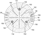
Fig. 8 is near the vertical view of the refrigerating gas jet box of expression gas quench system.
Fig. 9 is the amplification view of part of the lifter pin of expression elevating mechanism.
Embodiment
Below, the embodiment to microwave applicator of the present invention details based on accompanying drawing.Fig. 1 is the pie graph of the 1st embodiment of expression microwave applicator of the present invention; Fig. 2 is the figure of configuration of waveguide of microwave introduction device of the top plate portion of expression container handling, and Fig. 3 is the figure of lower surface of the showerhead of expression gas quench system (handling the gas gatherer).
< the 1st embodiment >
As shown in the figure, this microwave applicator 2 has the cylinder-shaped container handling 4 that is formed the section circle by inside such as aluminium, aluminium alloy or stainless steels.In this container handling 4, be discoideus supporting station 6 be provided with from container bottom with erecting through being pillar 8 cylindraceous.Above-mentioned supporting station 6 and pillar 8 are formed by metals such as aluminium, aluminium alloy or stainless steels.
Above-mentioned supporting station 6 be provided with to above extend many; Here be 3 fulcrum posts 10 (in figure l, only expressing 2), in the upper end of this fulcrum post 10; With the for example diameter as handled object be the back side butt of the semiconductor wafer W of 300mm, and with its supporting.This fulcrum post 10 is along the circumferencial direction of wafer W decentralized configuration equably.This fulcrum post 10 is little by dielectric constant, be the few dielectric substance of dielectric loss, for example quartzy, ceramic material forms, and this fulcrum post 10 forms hollow form, is tubulose.The internal diameter of the fulcrum post 10 of this hollow form for example is about 2mm.
In addition, be sealed in the above-mentioned pillar 8 cylindraceous, form chuck with confined space 12.And this chuck is communicated with the fulcrum post 10 of above-mentioned tubulose with confined space 12, constitutes vacuum chuck mechanism 14.Therefore, of the back, through this chuck is vacuumized with confined space,, attract the back side of wafer W to carry out vacuum suction in the upper end of this above-mentioned fulcrum post 10.
In addition, in order to heat, be provided with heater 16 by above-mentioned supporting station 6 wafer supported W.Particularly, this heater 16 has a plurality of light-emitting device unit 18 of the upper surface side that is configured in above-mentioned supporting station 6 here.This light-emitting device unit 18 disposes with the almost whole face of the lower surface of wafer W accordingly.And, on this each light-emitting device unit 18, be mounted with a plurality of light-emitting components such as LED element, laser diode, can heated chip W through the light that gives off from this light-emitting device unit 18.In addition, also can above-mentioned light-emitting device unit 18 be divided into concentric circles, can press each zone heated chip W independently with concentric circles.This each light-emitting device unit 18 is connected with supply lines 20, can supply capability through the heating power supply 22 that is arranged on this supply lines 20.
In addition, being provided with between above-mentioned supporting station 6 and the wafer W when taking out of of wafer W moved into, with its elevating mechanism of propping up, falling 24.Particularly, this elevating mechanism 24 has and forms circular-arc lifter plate 26 and many of being provided with in the upper surface side of this lifter plate 26, for example 3 (in Fig. 1, only illustrating 2) lifter pins 28.This lifter pin 28 almost becomes the mode of impartial distance to dispose according to the edge part along the rear side of wafer W, goes up and down wafer W is gone up and down to the top through making this lifter pin 28.
Therefore, above-mentioned lifter plate 26 engages with the upper end of the elevating lever 30 that above-mentioned supporting station 6 of perforation and container bottom extend downwards, and the bottom of this elevating lever 30 links with making its up and down actuator 32.In addition, in the breakthrough part of the container bottom of above-mentioned elevating lever 30, be inserted with the air-tightness of keeping in the container handling 4, and allow the metal bellows (bellows) 34 that elevating lever 30 is up and down.Promptly for example quartz, ceramic material form by dielectric substance for this lifter pin 28, lifter plate 26.
In addition, be formed with exhaust outlet 36 in the bottom of container handling 4, on this exhaust outlet 36, be connected with vacuum pumping system 38 the environmental gas exhaust in the container handling 4.This vacuum pumping system 38 has the exhaust channel 40 that is connected with above-mentioned exhaust outlet 36; On this exhaust channel 40, swim from it side towards downstream side be inserted with pressure-regulating valve 42 and vacuum pump 44 successively; As stated; But the pressure adjustment is carried out to the environmental gas in the container handling 4 in the limit, and the limit vacuumizes.
In addition, be provided with chuck with exhaust outlet 46 at the above-mentioned chuck of zoning with the container bottom of confined space 12.And, between the exhaust channel 40 of 44 in above-mentioned pressure-regulating valve 42 and vacuum pump and above-mentioned chuck are with exhaust outlet 46, be connected with exhaust channel 48 through chuck.In addition, be inserted with the 1st open and close valve 50 in exhaust channel 48,, can vacuumize with the environmental gas in the confined space 12 above-mentioned chuck and bring into play the vacuum chuck function that attracts the absorption wafer W through with the 1st open and close valve 50 states of being made as out at this chuck.
In addition, be connected through releasing pathway 52 between the exhaust channel 40 of the chuck of the upstream side of above-mentioned the 1st open and close valve 50 with exhaust channel 48 and the upstream side of above-mentioned pressure-regulating valve 42.And; In this releasing pathway 52, be inserted with the 2nd open and close valve 54; Through with the 2nd open and close valve 54 states of being made as out (the 1st open and close valve 50 is for closing state),, the processing space of accommodating wafer W and chuck remove clamping of wafer W thereby being become with pressing with the pressure of confined space 12.
And; Be inserted with the cowling panel 56 of ring-type between the edge part of the supporting station 6 in above-mentioned container handling 4 and the sidewall in the container handling 4; And in this cowling panel 56, be formed with a plurality of rectification hole 58; With the environmental gas rectification downwards on one side of the processing space S that is provided with wafer W, Yi Bian fluidly discharge to exhaust outlet 36.
In addition, on the sidewall of container handling 4, be formed with to be used to take out of and move into taking out of of wafer W and move into mouthfuls 60, and take out of at this and to move into mouthfuls 60 gate valve 62 is installed.And, in this container handling 4, be provided with the radiation thermometer 64 of the temperature that is used to measure above-mentioned wafer W.Particularly, this radiation thermometer 64 has the bottom that connects above-mentioned container handling 4 and supporting station 6 and the line probe 66 that for example is made up of optical fiber of extending, and the top of this line probe 66 and the back side of wafer W are approaching, be positioned at wafer W under.And, based on the light of deriving, obtain the temperature of wafer W by temperature instrumentation portion 68 through this line probe 66.
And; Temperature control part 70 to for example being made up of computer is notified the measured value of being obtained by this temperature instrumentation portion 68; Based on this measured value temperature; Control part 70 in the 1st embodiment, control above-mentioned heating power supply 22 with after the gas quench system stated, thereby the temperature of adjustment wafer W is controlled.
On the other hand, the top plate portion at above-mentioned container handling 4 is provided with the microwave introduction device 72 that is used in this container handling 4, importing microwave.In addition, here microwave refers to that frequency is for example for the electromagnetic wave of 300MHz~30GHz.Particularly, above-mentioned microwave introduction device 72 has many here, for example 4 microwave units 74 (in Fig. 1, only illustrating 2).In addition, the quantity of this microwave unit 74 is not restricted to 4 especially.Particularly, above-mentioned microwave unit 74 has the waveguide 76 that links with the vessel top board respectively.Also as shown in Figure 2, this waveguide 76 forms the section rectangular shape, equally spaced disposes along its circumferencial direction at the vessel top board.
In addition, be provided with by the microwave of opening importing port 78, and on this microwave importing port 78, the penetrating window 80 that for example is made up of dielectric substances such as quartz be installed across seal members such as O-ring seals 82 at the said vesse top plate portion.And the bottom of above-mentioned each waveguide 76 is installed on above-mentioned penetrating window 80, via this penetrating window 80 microwave is imported in the container handling 4.
Above-mentioned each waveguide 76 be inserted with circulator 84 midway, and its direction is crooked to right angle orientation, and is provided with microwave generator 86 at its base end part.Use the microwave of 2.456GHz, 5.8GHz, 28GHz here.Thus, the microwave that in above-mentioned microwave generator 86, takes place is propagated in above-mentioned waveguide 76, imports port 78 through microwave and imports in the container handling 4.In addition, on above-mentioned circulator 84, linking has dummy load 88, the function of performance insulator.In addition, dummy load 88 also can be provided with not according to each of each microwave unit 74, and shared between each microwave unit 74.
The action of above-mentioned microwave generator 86 is through 90 controls of microwave control part, so that the microwave that is taken place by each microwave generator 86 does not for example overlap.In addition, at this moment the power supply wave shape of magnetron can be got half-wave sine, trapezoidal wave, square wave etc.
In addition, the top plate portion at this container handling 4 is provided with the mixer 92 that is used to stir the microwave that imports through above-mentioned microwave introduction device 72.Particularly, be disposed at top plate portion in the container handling 4 under agitating auger oar 94.The rotating shaft 96 of this agitating auger oar 94 connects top plate portion airtightly via magnetic fluid seal spare 98, is rotated through rotation motor 99.And; Above-mentioned agitating auger oar 94 forms through the little high dielectric material of dielectric loss that is made up of composite ceramicses such as metal, PZT, quartzy sapphire etc.; Stir microwave through rotating this agitating auger oar 94, thereby prevent in container handling 4, to take place the standing wave of microwave.
In addition, between this agitating auger oar 94 and supporting station 6, be provided with, so that the non-cohesive upper surface of particulate that falls from above-mentioned agitating auger oar 94 in wafer W with the division board 100 that is divided in this container handling 4 up and down.This division board 100 is by the little dielectric substance of dielectric constant, and for example quartz, ceramic material, Teflon (Teflon) (registered trade mark) form, and does not absorb ground as far as possible and sees through microwave efficiently.Particularly, preferably use dielectric constant below 4.0, tan δ (dielectric loss angle tangent) is at the material of the dielectric substance below 0.0001 as this division board 100.In addition, be formed with a plurality of intercommunicating pores 102, to be communicated with the space up and down of this division board 100 at the periphery of this division board 100.
Thus, because the pressure reduction in the space up and down of division board 100 is eliminated the thickness of this division board 100 of attenuate of therefore can trying one's best.In addition; Preferred above-mentioned intercommunicating pore 102 is formed on same area with the cowling panel 56 formed rectification hole 58 that are arranged in its below on this above-below direction; In view of the above; Under the situation that the environmental gas in the space of taking in above-mentioned agitating auger oar 94 is discharged from through intercommunicating pore 102, can be not to the direction diffusion of wafer W, and directly towards under rectification hole 58 discharge with flowing downward.
In addition, in this container handling 4, be provided with the gas quench system 104 that cools off above-mentioned semiconductor wafer W through refrigerating gas.Here, above-mentioned gas cooling device 104 is also used as the processing gas gatherer 106 that in container handling 4, imports processing gas.Particularly, this gas quench system 104 has the showerhead 110 of below of top, the division board 100 of the wafer W of being disposed at here.Also as shown in Figure 3, this showerhead 110 has a plurality of of the concentric circles of being configured to, and is dispersion pipe 112A, the 112B of 2 big or small ring-types in illustrated example, and these dispersion pipes 112A, 112B connect through communicating pipe 114, and be interconnected.
And, in the lower face side of above-mentioned dispersion pipe 112A, 112B along its circumferencial direction uniformly-spaced being formed with most gas jetting holes 116, can be towards the jet surface refrigerating gas (processing gas) of the wafer W of below.This showerhead 110 is by the low material of dielectric constant, and for example formation such as quartz, ceramic material are not to absorb microwave as far as possible.
In addition, this showerhead 110 is supported by container side wall, and on this showerhead 110, is connected with gas passage 118.And, on this gas passage 118, be inserted with the such flow controller 120 of matter stream controller, can carry out flow control to refrigerating gas (processing gas) on one side, supply with on one side.In this case, in order to improve the cooling effectiveness of wafer W, showerhead 110 is provided with near wafer W ground gets final product.In this case, the distance between wafer W and the showerhead 110 is set to for example about 10~300mm.Supply with Ar gas or N here,
2Gas, or above-mentioned two gases as double as refrigerating gas and the gas of handling gas.As this refrigerating gas and processing gas, outside above-mentioned, also can use other rare gas such as He, Ne.In addition, also exist, use the situation as refrigerating gas, processing gas such as hydrogen, oxygen according to the mode of handling.
And as previously mentioned, said temperature control part 70 can be controlled the flow controller 120 of above-mentioned processing gas gatherer 106 and the temperature that heating power supply 22 is adjusted wafer W based on the measured value in the temperature instrumentation portion 68.
And; The action of the integral body of this microwave applicator 2 is for example controlled through the apparatus control portion 122 that is made up of microcomputer etc., and the program of carrying out the computer of this action is stored in the storage mediums 124 such as floppy disk, CD (Compact Disc), flash memory, hard disk.Particularly, through instruction, carry out supply, flow control, the supply of microwave, the electric power control of gas directly or indirectly, the control of chip temperature, processing pressure etc. from this apparatus control portion 122.
Next, the processing (annealing in process, modification processing etc.) of using above-mentioned microwave applicator 2 to carry out is described.At first; Semiconductor wafer W is accommodated in the container handling 4 through transferring arm (not shown) via the gate valve of opening 62; Lifter pin 28 through up and down elevating mechanism 24 carries wafer W on the fulcrum post 10 that places supporting station 6, and closing gate valve 62 is with sealing in the container handling 4.In this case, also can use the semiconductor substrate of monomer, for example silicon substrate is as above-mentioned semiconductor wafer W.
Here; The vacuum pump 44 of vacuum pumping system 38 is by Continuous Drive; Through with chuck with the 1st open and close valve 50 states of being made as out (the 2nd open and close valve 54 is for closing state) that plug in the exhaust channel 48; The chuck of the below of supporting station 6 vacuumized with confined space 12 reduce pressure, thus, performance chuck function is carried out vacuum suction to the back side of carrying the wafer W on the fulcrum post 10 that places hollow form and is adsorbed fixed wafer W.In addition, for removing this vacuum suction, through above-mentioned the 1st open and close valve 50 is made as the state of closing, and the 2nd open and close valve 54 states of being made as out that plug in the releasing pathway 52 are made chuck use confined space 12 and handle space S for getting final product with pressing.
Next, if that kind has been adsorbed wafer W as stated, the showerhead 110 that just passes through the processing gas gatherer 106 of double as gas quench system 104 is handled Ar gas, the N of gas on one side to conduct
2Gas carries out flow control, to container handling 4 in supply with on one side.In this case, also rely on processing mode though handle the operation pressure of space S, for example for about number 100Torr, in order to bring into play the chuck function, the pressure that chuck uses confined space 12 is for than its low several 10mmTorr.
In addition, the heating power supply 22 through heater 16 by the LED element, the laser diode radiant light that load in this light-emitting device unit 18, impinges upon the back side of wafer W to each light-emitting device unit 18 supply capability, wafer W is heated up be heated to the temperature of regulation.Meanwhile, microwave takes place in the microwave generator 86 of each microwave unit 74 of driving microwave introduction device 72.This microwave is propagated in waveguide 76, and imports port 78 through each microwave that forms at the top plate portion of container handling 4 and be imported in the container handling 4, this microwave and then see through the surface irradiation of division board 100 to wafer W.Like this, when microwave irradiation was on wafer W, through the heating of electromagnetic waves such as joule heating, magnetic heating, induction heating, wafer W can more promptly be heated, and its result can carry out annealing in process, modification processing etc.
Here,, then might produce and discharge to high temperature than under the condition with higher at the technological temperature of wafer if only desire through microwave heating in wafer surface.So, as stated, establish the heating that heater 16 is assisted wafer through other, can not be heated to high temperature in wafer surface with producing discharge.At this moment chip temperature is for example in the scope about 100~400 ℃.In addition, in the processing of this microwave, make agitating auger oar 94 rotations of the mixer 92 that is arranged on the vessel top board.Like this, can stir the microwave that imports in the container handling 4 through agitating auger oar 94 and prevent standing wave takes place in container handling 4, the inner evenness of processing of wafers is improved.
In such processing of wafers,, measure the temperature of wafer W continuously through temperature survey portion 68 through introduce the radiant light of wafer W in the line probe 66 of the radiation thermometer 64 of the rear side of wafer W configuration.This measured value is transferred to temperature control part 70; Temperature control part 70 increases and decreases the supply capability to light-emitting device unit 18 based on this measured value control heating power supply 22; And control gaseous cooling device (handling the gas gatherer) 104 flow controller 120 increases and decreases the flow of refrigerating gas (processing gas), and adjustment is the temperature of control wafer W.
Here; The absorptivity that has a microwave relies on the temperature of wafer W and situation about changing; Therefore the mode of for example keeping the temperature of regulation according to the supply capability that makes microwave for certain and wafer W is here controlled the supply capability to light-emitting device unit 18, perhaps controls the flow of the refrigerating gas on the surface that blows to wafer W.Thus, can be with the temperature of wafer W and the supply capability control independently separately of microwave.
In addition, because the rotation of above-mentioned agitating auger oar 94 can worry to produce particulate etc., the particulate of generation is accepted by the division board 100 of its below, therefore can not fall to the surface of wafer W.In addition; Flow under the situation of handling space S via intercommunicating pore 102 at the environmental gas of the particulate that produces with this regional space; The environmental gas flow direction of this outflow is positioned at the rectification hole 58 of the cowling panel 56 under it, therefore can prevent also that based on this some particulate is attached to the surface of wafer W.
As above such; On one side to semiconductor wafer W irradiating microwaves as handled object; Measure the temperature of handled object on one side with radiation thermometer 64, control heater 16 and gas quench system 104 based on this measured value, thereby can adjust the temperature of handled object independently with the exposure of microwave.
< the 2nd embodiment >
Next, the 2nd embodiment to microwave applicator of the present invention describes.According to the processing mode of semiconductor wafer W, need not improve adding heat and just can fully chip temperature be warming up to the temperature range as target sometimes with the temperature of wafer W is such through microwave irradiation.Under these circumstances, can not need the heater 16 that uses among in front the 1st embodiment.Fig. 4 is the pie graph of the 2nd embodiment of the such microwave applicator of the present invention of expression.In addition, in Fig. 4, to marking same reference numerals, and omit its explanation with Fig. 1~identical component part of part shown in Figure 3 of front.
As shown in Figure 4, become here and from formation shown in Figure 1, remove the light-emitting device unit 18 that constitutes heater 16 and the formation of heating power supply 22 (with reference to Fig. 1), other formation is identical with formation shown in Figure 1.In addition, owing to removed heater 16, so temperature control part 70 carries out the temperature adjustment of wafer W through the flow with gas quench system 104 (handling gas gatherer 106) control refrigerating gas.
In this case, also can bring into play the action effect same with the 1st embodiment.That is, can be on one side to semiconductor wafer irradiating microwaves as handled object, with radiation thermometer 64 measure the temperature of handled objects on one side, based on this measured value control gaseous cooling device 104, thereby adjust the temperature of handled object.
< the 3rd embodiment >
Next, the 3rd embodiment to microwave applicator of the present invention describes.According to the processing mode of semiconductor wafer W, technological temperature need not cool off the temperature of wafer W with gas quench system than higher sometimes, and the control through heater just can be controlled to be the temperature as target with chip temperature fully.Under these circumstances, can not need the gas quench system 104 that uses among in front the 1st embodiment.Fig. 5 is the pie graph of the 3rd embodiment of the such microwave applicator of the present invention of expression.In addition, in Fig. 5, to marking same Reference numeral, and omit its explanation with Fig. 1~identical component part of part shown in Figure 3 of front.
As shown in Figure 5, become the formation of from formation shown in Figure 1, removing gas quench system 104 here, other formation is identical with formation shown in Figure 1.That is, under situation shown in Figure 1, gas quench system 104 and the mutual dual-purpose of processing gas gatherer 106 quilts, therefore here showerhead 110, flow controller 120 play a role as handling gas gatherer 106.In addition, owing to removed gas quench system 104, so temperature control part 70 carries out the temperature adjustment of wafer W through the heating power supply 22 of only controlling heater 16.
In this case, also can bring into play the action effect same with the 1st embodiment.That is, can be on one side to semiconductor wafer irradiating microwaves as handled object, with radiation thermometer 64 measure the temperature of handled objects on one side, based on this measured value control heater 16, thereby adjust the temperature of handled object.
< variation of gas quench system (handling the gas gatherer) >
Next, the variation to gas quench system (handling the gas gatherer) describes.Among the 1st~the 3rd embodiment of explanation, gas quench system 104 is perhaps handled 2 dispersion pipe 112A, the 112B (with reference to Fig. 3) that gas gatherer 106 has the concentric circles of being configured to, but is not limited thereto, and also can use nozzle in front.Fig. 6 is the figure of the variation of expression gas quench system (handling the gas gatherer).In addition, in Fig. 6,, and omit its explanation to the same Reference numeral of component part mark identical with the figure of front explanation.
As shown in Figure 6, showerhead 110 (with reference to Fig. 1) is not set here, its mode that replaces with the sidewall that connects container handling 4 is provided with a plurality of gas nozzles 130, the top that makes this gas nozzle 130 from oblique upper closely towards the surface of wafer W.The refrigerating gas that will be sprayed thus, (processing gas) directly blows to the surface of wafer W and improves cooling effectiveness.In addition, the quantity of this gas nozzle 130 is not limited especially.
In addition, in the explanation of each above embodiment (removing the 3rd embodiment), gas quench system 104 is mutual dual-purposes with handling gas gatherer 106, but is not limited thereto, and also can both be separated, and is provided with independently respectively.The device that for example also can use the gas nozzle 130 with that kind shown in Figure 6 is as gas quench system 104; The device that also can use the showerhead 110 with that kind shown in Figure 1 perhaps can also exchange both and use as handling gas gatherer 106.In addition, use the light-emitting device unit 18 (with reference to Fig. 1) that possesses LED element, laser diode as heater 16 here, but be not limited thereto, also can use heating lamps such as Halogen lamp LED, mercury vapor lamp, flash lamp.
< the 4th embodiment >
Next, the 4th embodiment to microwave applicator of the present invention describes.According to the processing mode of semiconductor wafer, sometimes with the 2nd embodiment of front likewise, the purpose of the influence of for example not being heated with protection basilar memebrane etc. is want to suppress the treatment temperature of wafer W lower.Under these circumstances, the heater 16 that need in the 1st embodiment, not use, and therefore chip temperature need cool off wafer effectively through the adding heat and also can considerably rise of microwave irradiation in processing.
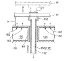
Fig. 7 is the pie graph of the 4th embodiment of the such microwave applicator of the present invention of expression, and Fig. 8 is near the vertical view the refrigerating gas jet box of expression gas quench system, and Fig. 9 is the amplification view of part of the lifter pin of expression elevating mechanism.In Fig. 7~Fig. 9, to marking identical Reference numeral, and omit its explanation with Fig. 1~identical component part of part shown in Figure 6 of front.
As shown in Figure 7, in the microwave applicator of the 4th embodiment, likewise be provided with microwave introduction device 72 and mixer 92 at the top plate portion of container handling 4 and the 1st embodiment of front.But, be not provided with the division board 100 and the showerhead 110 (with reference to Fig. 1) of the obstacle that becomes microwave irradiation, can import port 78 directly to semiconductor wafer W irradiating microwaves from the microwave of the microwave introduction device 72 that is arranged at top plate portion as handled object.
And, in this container handling 4, be provided with: have the lifter pin 132 of the above-mentioned semiconductor wafer W of supporting and the elevating mechanism 134 that this wafer W is gone up and down; With the gas quench system 136 that following injection refrigerating gas to above-mentioned wafer W cools off, in addition, above-mentioned elevating mechanism 134 is provided with the vacuum chuck mechanism 138 that makes wafer W absorption.
Particularly, above-mentioned elevating mechanism 134 has above-mentioned lifter pin 132, links and the lifter plate 140 of supporting lifter pin 132, the elevating lever 142 that its upper end is linked to this lifter plate 140 and the actuator 144 that this elevating lever 142 is gone up and down with the bottom of this lifter pin 132.Above-mentioned lifter pin 132 on circumference uniformly-spaced to dispose many, for example 3 (in Fig. 7, only having write down 2) (with reference to Fig. 8).
And above-mentioned lifter plate 140 for example forms circular, and the bottom of above-mentioned lifter pin 132 is linked to the upper surface of this lifter plate 140 with engaging.In addition, this lifter plate 140 also can form circular shape or discoideus.And, make the edge part of lower surface that the upper end of above-mentioned lifter pin 132 is connected to above-mentioned wafer W with its supporting.
The upper end of above-mentioned elevating lever 142 is linked to an end of above-mentioned lifter plate 140 with engaging, and extend downwards the bottom of this elevating lever 142, and connects the bottom of container handling 4.And side links in the bottom of this elevating lever 142 has above-mentioned actuator 144, and above-mentioned lifter plate 140 and lifter pin 132 integratedly can go up and down.In addition, be inserted with metal bellows 146, keep the air-tightness in the container handling 4, and allow that elevating lever 142 is up and down at the breakthrough part of the container bottom of above-mentioned elevating lever 142.
Here, above-mentioned lifter pin 132, lifter plate 140 and elevating lever 142 are by to the promptly quartzy (SiO of the few dielectric substance of the absorption of microwave
2), aluminium oxide (Al
2O
3), aluminium nitride (AlN), carborundum ceramic materials such as (SiC) form.In the present embodiment, in above-mentioned each lifter pin 132, be formed with and attract hole 150, this attracts the part of the hole above-mentioned vacuum chuck of 150 formation mechanism 138.Particularly, above-mentioned attraction hole 150 forms along its length direction at the central part of lifter pin 132, in addition, is formed with attraction path 152 in the inside of above-mentioned lifter plate 140 and elevating lever 142 along them.This attracts the top ends of path 152 to be communicated with the bottom in the attraction hole 150 that in above-mentioned lifter pin 132, forms.
The bottom of the attraction path 152 that in above-mentioned elevating lever 142, forms in addition, is via allowing that elevating lever 142 up and down metal bellowss 154 are connected with exhaust channel 48 with chuck.And this chuck is connected with the pressure-regulating valve 42 of vacuum pumping system 38 and the exhaust channel 40 between the vacuum pump 44 with the other end of exhaust channel 48.
And; Be inserted with the 1st open and close valve 50 at this chuck in exhaust channel 48; Through with the 1st open and close valve 50 states of being made as out, can vacuumize in the above-mentioned attraction path 152 and attraction hole 150 interior environmental gas and bring into play the vacuum chuck function that attracts the absorption wafer W.
In addition, be connected through releasing pathway 52 between the exhaust channel 40 of the chuck of the upstream side of above-mentioned the 1st open and close valve 50 with exhaust channel 48 and the upstream side of above-mentioned pressure-regulating valve 42.And; In this releasing pathway 52, be inserted with the 2nd open and close valve 54; Through with the 2nd open and close valve 54 states of being made as out (the 1st open and close valve 50 is for closing state), can take in the processing space of wafer W and attract the pressure in the hole 150 to be set to remove clamping of wafer W with pressing.
Here, the upper end of above-mentioned lifter pin 132 that kind as shown in Figure 9 is by hole enlargement, and the diameter that increases as the attraction port 156 that attracts the upper end in the hole 150 enlarges the attraction area, so that wafer W is produced suitable attraction.In this case, attract the diameter of port 156 be set to wafer W not by as after spray to the back side of wafer W stating refrigerating gas blow afloat and do not produce the size of excessive attraction that kind to the top.The size of the diameter D1 of this attraction port 156 depends on the exhaust attraction power of vacuum pumping system 38, for example is the interior size of scope of 2~10mm, for example is set to 3mm here.
And the above-mentioned gas cooling device 136 that the lower surface of 132 wafer supported W of above-mentioned lifter pin is sprayed refrigerating gas has the refrigerating gas jet box 158 of the below that is disposed at above-mentioned wafer W.This refrigerating gas jet box 158 forms the case shape of the circle bigger slightly than the diameter of wafer W or container-like.Pillar 8 supportings that this refrigerating gas jet box 158 is erected by the bottom from container handling 4.In this case, also can as the 1st embodiment of front, use big 1 pillar 8 cylindraceous of diameter, perhaps also can use the little columned many pillars 8 of diameter.
Here, support above-mentioned refrigerating gas jet box 158 through the little columned many pillars 8 of diameter.And, be formed with gas diffusion chamber 160 in the inside of this refrigerating gas jet box 158.On the upper surface zoning wall of this refrigerating gas jet box 158, cover whole face and almost be provided with a plurality of gas jetting holes 162 equably dispersedly, through spraying refrigerating gas to the lower surface of wafer W, can cool off above-mentioned wafer W from each gas jetting hole 162.
In addition, in above-mentioned refrigerating gas jet box 158, be formed with pin accordingly along the vertical direction and insert siphunculus 164, make above-mentioned lifter pin 132 insert to insert in the siphunculus 164 and lead to along this pin with the position that is provided with of above-mentioned lifter pin 132.The slotting siphunculus 164 interior quilts of this pin zoning airtightly are above-mentioned gas diffuser chamber 160.Above-mentioned refrigerating gas jet box 158 can pass through formation such as the few metal of metallic pollutions such as aluminium, aluminium alloy, quartz, ceramic material.
In addition, gas introduction tube 166 extends downwards from above-mentioned refrigerating gas jet box 158, and this gas introduction tube 166 connects downwards via seal members such as O-ring seals 168.And, on this gas introduction tube 166, be connected with gas passage 118.On this gas passage 118, be inserted with matter stream controller such flow controller 120, open and close valve 170, can be on one side to Ar, N
2Carry out flow control Deng refrigerating gas, supply with on one side.As above-mentioned refrigerating gas, also can use other rare gas such as He, Ne.
And; Between the edge part of above-mentioned refrigerating gas jet box 158 and the sidewall in the container handling 4, be inserted with the cowling panel 56 of ring-type; And in this cowling panel 56, be formed with a plurality of rectification hole 58; With the environmental gas rectification downwards on one side of the processing space S that is provided with wafer W, Yi Bian fluidly discharge to exhaust outlet 36.
Next, the processing (annealing in process, modification processing etc.) of using above-mentioned microwave applicator to carry out is described.At first; Semiconductor wafer W is accommodated in the container handling 4 through transferring arm (not shown) via the gate valve of opening 62; Lifter pin 132 through making elevating mechanism 134 rises; Lower surface with the upper end jack-up wafer W of lifter pin 132 receives wafer W, in that to make transferring arm retreat back closing gate valve 62 airtight in container handling 4.In this case, also can use the semiconductor substrate of monomer, for example silicon substrate is as above-mentioned semiconductor wafer W.
Here; The vacuum pump 44 of vacuum pumping system 38 is by Continuous Drive; Through with the chuck of vacuum chuck mechanism 138 with the 1st open and close valve 50 states of being made as out (the 2nd open and close valve 54 is for closing state) that plug in the exhaust channel 48; To in the attraction path 152 that in the lifter plate 140 of elevating mechanism 134 and elevating lever 142, forms and the environmental gas in the attraction hole 150 of formation in lifter pin 132 vacuumize and reduce pressure; Bring into play the chuck function thus, carry out vacuum suction and adsorb fixed wafer W carrying the back side place the wafer W on the lifter pin 132.In addition, for removing this vacuum suction, through above-mentioned the 1st open and close valve 50 is made as the state of closing, and with the 2nd open and close valve 54 states of being made as out that plug in the releasing pathway 52 with chuck with confined space 12 with handle space S and form with pressing and get final product.
Next, as above-mentioned,, lifter pin 132 fallen to the position of carrying out technology lifter pin 132 is stopped if having adsorbed wafer W.In this case, the upper surface of wafer W and refrigerating gas jet box 158 is positioned at its top non-contiguously and stops, and under this state, begins technology.
And, driving gas cooling device 136, Yi Bian to Ar gas, N as refrigerating gas
2Gas carries out flow control, to gas diffusion chamber 160 in supply with and make its diffusion on one side, to this refrigerating gas of top ejection, the lower surface of cover wafers W integrally sprays refrigerating gas, begins the cooling of wafer W from each gas jetting hole 162.At this moment, between the upper surface of the lower surface of wafer W and refrigerating gas jet box 158, form the gap of the amplitude H1 of regulation, the back side that can spread all over wafer W from the refrigerating gas of each gas jetting hole 162 ejection equably is whole.The amplitude H1 in above-mentioned gap is for example in the scope of number mm~number cm.In this case, the operation pressure of handling space S also depends on processing mode, and for example for about number 100Torr, in order to bring into play the chuck function, attracting the pressure in the hole 150 is than its low several 10mmTorr.
Meanwhile, microwave takes place in the microwave generator 86 of each microwave unit 74 of driving microwave introduction device 72.This microwave is propagated in waveguide 76, imports port 78 through each microwave that in the top plate portion of container handling 4, forms and is imported in the container handling 4, and this microwave is directly to the surface irradiation of wafer W.Like this, when microwave irradiation was on wafer W, because the heating of electromagnetic waves such as joule heating, magnetic heating, induction heating, wafer W can be by heating promptly, and its result can carry out annealing in process, modification processing etc.
Here, because the absorption of microwave, wafer W heats up, and therefore sprays refrigerating gas by each gas jetting hole 162 of refrigerating gas jet box 158 to the lower surface of wafer W as stated and cools off wafer W.In this case, refrigerating gas sprays to the lower surface of wafer W almost evenly, therefore can improve the inner evenness of chip temperature.The technological temperature of wafer at this moment is for example in the scope about 100~400 ℃.
In addition,, on wafer W, produce buoyancy upwards,, therefore can prevent the offset of wafer W, and cool off reliably from the lifter pin 132 double as vacuum chuck mechanisms 138 of rear support wafer W owing to spray refrigerating gas to the lower surface of wafer W.In addition; Here; The diameter that suitably is adjusted at the attraction port 156 that the upper end of lifter pin 132 is provided with carries out optimization, thus be arranged in attraction that this attractions port 156 produces be almost identical by buoyancy to the refrigerating gas generation of the lower surface injection of wafer W or attraction one general plan big.Therefore, flexible even heat takes place wafer W, this heat is flexible is also easily allowed, between the upper surface of the lower surface of wafer W and lifter pin 132, does not produce big frictional force, and generation, the wafer lower surface that can suppress particulate damage.
In addition; Though wafer W absorbs microwave; But the amplitude H1 in the gap of the lower surface of preferred wafer W and the upper surface of refrigerating gas jet box 158 changes according to the condition of the microwave of irradiation; Owing to carry out the irradiation of microwave, therefore can amplitude H1 be set as the processing of carrying out wafer W after the suitable value with the state that wafer W is remained on the lifter pin 132.Like this, in the present embodiment, can be on one side to as the for example semiconductor wafer W of handled object irradiating microwaves effectively, Yi Bian cool off handled object effectively.
In addition, here, the flow of refrigerating gas is set regularly; But be not limited thereto; The radiation thermometer of measuring chip temperature also can be set as the 1st embodiment, the flow of refrigerating gas be carried out FEEDBACK CONTROL through this detected temperatures, thus the temperature of control wafer W.
In addition,, in container handling 4, only import refrigerating gas here, exist according to processing mode and use H
2Deng reducing gas, O
2Situation Deng the processing gas of oxidizing gas etc.; Under these circumstances; Constitute on the gas passage 118 of above-mentioned gas cooling device 136 the connection processing gas passage and carry out flow control on one side, import and handle gas on one side, supply with refrigerating gas and handle gas and get final product with admixture.In this case, gas quench system can be by mutual dual-purpose with processing gas gatherer.
In addition, importing under the situation of above-mentioned processing gas, also can with gas quench system 136 discretely in container handling 4 above the processing gas gatherer 106 that kind as shown in Figure 1 has showerhead 110 is set.
In addition; And then in above-mentioned the 4th embodiment, used refrigerating gas jet box 158 as gas quench system 136, but be not limited thereto; For example also can as Fig. 1 and shown in Figure 3, use by the showerhead 110 that constitutes many dispersion pipe 112A, 112B and communicating pipe 114.In this case, this showerhead 110 is disposed at the below of wafer W, each gas jetting hole 116 is sprayed refrigerating gas towards the lower surface of last direction wafer W.In addition, according to processing mode, the amplitude H1 (with reference to Fig. 9) in the gap between the lower surface that also can make wafer W and the upper surface of refrigerating gas jet box 158 is different.
In addition; Here; As handled object is that example is illustrated with the semiconductor wafer; Also comprise compound semiconductor substrates such as silicon substrate, GaAs, SiC, GaN in this semiconductor wafer, be not limited to these substrates in addition, the glass substrate that in liquid crystal indicator, uses, ceramic substrate etc. also can be used the present invention.
Description of reference numerals
2 microwave applicators; 4 container handlings; 6 supporting stations; 10 fulcrum posts; 12 chucks are used confined space; 14 vacuum chuck mechanisms; 16 heaters; 18 light-emitting device unit; 22 heating power supplies; 38 vacuum pumping systems; 64 radiation thermometers; 66 line probe; 68 temperature survey portions; 70 temperature control parts; 72 microwave introduction devices; 74 microwave units; 86 microwave generators; 92 mixers; 94 agitating auger oars; 104 gas quench systems; 106 handle the gas gatherer; 110 showerheads; 132 lifter pins; 134 elevating mechanisms; 136 gas quench systems; 138 vacuum chuck mechanisms; 140 lifter plates; 142 elevating levers; 144 actuators; 150 attraction holes; 152 attract path; 158 refrigerating gas jet boxs; 160 gas diffusion chamber; 162 gas jetting holes; 164 pins are inserted siphunculus; W semiconductor wafer (handled object)
Claims (20)
1. a microwave applicator is handled the handled object irradiating microwaves, and this microwave applicator is characterised in that to possess:
Can carry out the container handling of vacuum exhaust;
Support the supporting station of said handled object;
In said container handling, import the processing gas gatherer of handling gas;
In said container handling, import the microwave introduction device of microwave;
Heat the heater of said handled object;
Cool off the gas quench system of said handled object through refrigerating gas;
Measure the radiation thermometer of the temperature of said handled object; With
Temperature control part, its measured value based on said radiation thermometer is controlled said heater and said gas quench system, thereby adjusts the temperature of said handled object.
2. a microwave applicator is handled the handled object irradiating microwaves, and this microwave applicator is characterised in that to possess:
Can carry out the container handling of vacuum exhaust;
Support the supporting station of said handled object;
In said container handling, import the processing gas gatherer of handling gas;
In said container handling, import the microwave introduction device of microwave;
Cool off the gas quench system of said handled object through refrigerating gas;
Measure the radiation thermometer of the temperature of said handled object; With
Temperature control part, its measured value based on said radiation thermometer is controlled said gas quench system, thereby adjusts the temperature of said handled object.
3. microwave applicator according to claim 1 and 2 is characterized in that,
Said gas quench system has the showerhead of the top that is arranged at said supporting station.
4. microwave applicator according to claim 1 and 2 is characterized in that,
Said gas quench system and said gas gatherer are by mutual dual-purpose.
5. a microwave applicator is handled the handled object irradiating microwaves, and this microwave applicator is characterised in that to possess:
Can carry out the container handling of vacuum exhaust;
Support the supporting station of said handled object;
In said container handling, import the processing gas gatherer of handling gas;
In said container handling, import the microwave introduction device of microwave;
Heat the heater of said handled object;
Measure the radiation thermometer of the temperature of said handled object; With
Temperature control part, its measured value based on said radiation thermometer is controlled said heater, thereby adjusts the temperature of said handled object.
6. according to any described microwave applicator in the claim 1~2,5, it is characterized in that,
Top plate portion in said container handling is provided with the mixer of stirring by the microwave of said microwave introduction device importing.
7. microwave applicator according to claim 6 is characterized in that,
Between said mixer and said supporting station, be provided with the division board that constitutes by dielectric.
8. microwave applicator according to claim 7 is characterized in that,
Periphery at said division board is formed with the intercommunicating pore that is used to be communicated with the space up and down that is kept apart by said division board.
9. according to any described microwave applicator in the claim 1~2,5, it is characterized in that,
Said handled object is supported on the said supporting station across a plurality of fulcrum posts.
10. microwave applicator according to claim 9 is characterized in that,
Said fulcrum post is a hollow, and forms the vacuum chuck mechanism at the back side of the said handled object of vacuum suction.
11. microwave applicator according to claim 10 is characterized in that,
The bottom of said supporting station forms the chuck that is vacuumized for a part that forms said vacuum chuck mechanism and uses confined space, and said chuck is connected with confined space and said fulcrum post.
12. a microwave applicator is handled the handled object irradiating microwaves, this microwave applicator is characterised in that to possess:
Take in the container handling of said handled object;
Environmental gas in the said container handling is carried out the vacuum pumping system of exhaust;
In said container handling, import the microwave introduction device of microwave;
Lower surface to said handled object sprays the gas quench system that refrigerating gas cools off;
Have the lifter pin of the said handled object of supporting and the elevating mechanism that said handled object is gone up and down; With
Vacuum chuck mechanism, it has the attraction hole that is formed in the said lifter pin, through forming by attracting path that said attraction hole is connected with said vacuum pumping system.
13. microwave applicator according to claim 12 is characterized in that,
Said gas quench system has the refrigerating gas jet box, and said refrigerating gas jet box is disposed at the below of said handled object, is formed with a plurality of gas jetting holes at upper surface, and in set inside gas diffusion chamber is arranged.
14. microwave applicator according to claim 12 is characterized in that,
Said gas quench system has a plurality of dispersion pipes that below said handled object, are configured to concentric circles, said dispersion pipe towards above ground be formed with a plurality of gas jetting holes.
15. according to any described microwave applicator in the claim 12~14, it is characterized in that,
Said elevating mechanism has:
The lifter plate of said lifter pin is supported in the bottom that links said each lifter pin;
Its upper end is linked to the elevating lever of said lifter plate; With
Make the actuator of said lifter rod lifting.
16. microwave applicator according to claim 15 is characterized in that,
Said attraction path is along said lifter plate and said elevating lever and form.
17. according to any described microwave applicator in the claim 12~14, it is characterized in that,
Have and in said container handling, import the processing gas gatherer of handling gas.
18. microwave applicator according to claim 17 is characterized in that,
Said gas quench system and said processing gas gatherer are by mutual dual-purpose.
19. according to any described microwave applicator in the claim 12~14, it is characterized in that,
Top plate portion in said container handling is provided with the mixer of stirring by the microwave of said microwave introduction device importing.
20. according to any described microwave applicator in the claim 12~14, it is characterized in that,
When said handled object is processed, between the lower surface of said handled object and said gas quench system, be formed with the gap of the amplitude of regulation.
Applications Claiming Priority (4)
| Application Number | Priority Date | Filing Date | Title |
|---|---|---|---|
| JP2011037396 | 2011-02-23 | ||
| JP2011-037396 | 2011-02-23 | ||
| JP2011-192069 | 2011-09-02 | ||
| JP2011192069A JP5982758B2 (en) | 2011-02-23 | 2011-09-02 | Microwave irradiation device |
Publications (1)
| Publication Number | Publication Date |
|---|---|
| CN102651923A true CN102651923A (en) | 2012-08-29 |
Family
ID=46651903
Family Applications (1)
| Application Number | Title | Priority Date | Filing Date |
|---|---|---|---|
| CN2012100445966A Pending CN102651923A (en) | 2011-02-23 | 2012-02-23 | Microwave irradiation apparatus |
Country Status (5)
| Country | Link |
|---|---|
| US (1) | US9224623B2 (en) |
| JP (1) | JP5982758B2 (en) |
| KR (1) | KR101332252B1 (en) |
| CN (1) | CN102651923A (en) |
| TW (1) | TW201251515A (en) |
Cited By (2)
| Publication number | Priority date | Publication date | Assignee | Title |
|---|---|---|---|---|
| CN103008203A (en) * | 2012-12-13 | 2013-04-03 | 京东方科技集团股份有限公司 | Film curing device |
| CN108660513A (en) * | 2017-03-28 | 2018-10-16 | 上海新昇半导体科技有限公司 | A kind of device and method reducing wafer defect |
Families Citing this family (24)
| Publication number | Priority date | Publication date | Assignee | Title |
|---|---|---|---|---|
| US9048270B2 (en) * | 2007-03-08 | 2015-06-02 | Joseph M. Wander | Apparatus and method for heating semiconductor wafers via microwaves |
| JP2014056806A (en) * | 2012-02-27 | 2014-03-27 | Tokyo Electron Ltd | Microwave heating treatment apparatus, and heating treatment method |
| CN103389156A (en) * | 2012-05-08 | 2013-11-13 | 全亿大科技(佛山)有限公司 | Light-emitting diode detection measuring implement |
| JP5738814B2 (en) | 2012-09-12 | 2015-06-24 | 株式会社東芝 | Microwave annealing apparatus and semiconductor device manufacturing method |
| US9750091B2 (en) * | 2012-10-15 | 2017-08-29 | Applied Materials, Inc. | Apparatus and method for heat treatment of coatings on substrates |
| JP2014090058A (en) * | 2012-10-30 | 2014-05-15 | Tokyo Electron Ltd | Microwave heat treatment apparatus and method |
| CN103792474A (en) * | 2012-11-02 | 2014-05-14 | 全亿大科技(佛山)有限公司 | Light emitting diode detection measuring tool |
| US9989417B2 (en) * | 2013-09-12 | 2018-06-05 | Goji Limited | Temperature measurement arrangement |
| JP2015103726A (en) * | 2013-11-27 | 2015-06-04 | 東京エレクトロン株式会社 | Microwave heat treatment device and microwave heat treatment method |
| JP2015187955A (en) * | 2014-03-27 | 2015-10-29 | 日本碍子株式会社 | microwave irradiation method |
| JP6390153B2 (en) * | 2014-04-30 | 2018-09-19 | 富士電機株式会社 | Heat treatment equipment |
| KR101563495B1 (en) * | 2014-07-31 | 2015-10-27 | 한국에너지기술연구원 | Device for controlling sample temperature during opto-electronic measurement and device for measuring solar cell by using the same |
| JP6435135B2 (en) * | 2014-08-26 | 2018-12-05 | 株式会社日立ハイテクノロジーズ | Plasma processing equipment |
| US10403880B2 (en) * | 2015-09-11 | 2019-09-03 | Iftikhar Ahmad | Apparatus and method for processing battery electrodes |
| US11104502B2 (en) * | 2016-03-01 | 2021-08-31 | Jeffrey S. Melcher | Multi-function compact appliance and methods for a food or item in a container with a container storage technology |
| WO2017149663A1 (en) * | 2016-03-01 | 2017-09-08 | 株式会社日立国際電気 | Substrate treatment apparatus, method for manufacturing semiconductor device, and recording medium |
| KR102538177B1 (en) | 2017-11-16 | 2023-05-31 | 삼성전자주식회사 | Deposition apparatus including upper shower head and lower shower head |
| KR102404061B1 (en) * | 2017-11-16 | 2022-05-31 | 삼성전자주식회사 | Deposition apparatus including upper shower head and lower shower head |
| US10747968B2 (en) | 2017-11-22 | 2020-08-18 | Jeffrey S. Melcher | Wireless device and selective user control and management of a wireless device and data |
| JP7161854B2 (en) * | 2018-03-05 | 2022-10-27 | 東京エレクトロン株式会社 | inspection equipment |
| JP7079317B2 (en) * | 2018-03-23 | 2022-06-01 | 株式会社Kokusai Electric | Substrate processing equipment, semiconductor equipment manufacturing methods and programs |
| WO2019186655A1 (en) * | 2018-03-26 | 2019-10-03 | 株式会社Kokusai Electric | Substrate processing device, semiconductor device production method and program |
| JP7338441B2 (en) * | 2019-12-13 | 2023-09-05 | ウシオ電機株式会社 | light heating device |
| WO2023047922A1 (en) * | 2021-09-24 | 2023-03-30 | 株式会社Kokusai Electric | Substrate processing device, method for manufacturing semiconductor device, and program |
Citations (9)
| Publication number | Priority date | Publication date | Assignee | Title |
|---|---|---|---|---|
| US6736930B1 (en) * | 1999-03-29 | 2004-05-18 | Tokyo Electron Limited | Microwave plasma processing apparatus for controlling a temperature of a wavelength reducing member |
| TW200503114A (en) * | 2003-06-17 | 2005-01-16 | Tokyo Electron Ltd | Single-substrate heat-processing apparatus for semiconductor processing system |
| CN1618118A (en) * | 2002-02-28 | 2005-05-18 | 东京毅力科创株式会社 | Heat treatment device |
| CN1945807A (en) * | 2004-10-07 | 2007-04-11 | 应用材料公司 | Apparatus for controlling temperature of a substrate |
| CN101147244A (en) * | 2005-07-28 | 2008-03-19 | 东京毅力科创株式会社 | Substrate processing method and substrate processing apparatus |
| CN101361169A (en) * | 2006-01-17 | 2009-02-04 | 大日本网屏制造株式会社 | Substrate processing apparatus and substrate processing method |
| CN101365823A (en) * | 2006-06-20 | 2009-02-11 | 东京毅力科创株式会社 | Film forming apparatus and film forming method |
| CN101416276A (en) * | 2005-11-11 | 2009-04-22 | Dsg科技公司 | Thermal processing system, components, and methods |
| CN101641768A (en) * | 2007-03-23 | 2010-02-03 | 东京毅力科创株式会社 | Placing table structure and processing apparatus using the same |
Family Cites Families (22)
| Publication number | Priority date | Publication date | Assignee | Title |
|---|---|---|---|---|
| JPS6035992Y2 (en) * | 1980-11-11 | 1985-10-25 | 株式会社東芝 | High frequency heating device |
| JPH0752749B2 (en) * | 1986-02-19 | 1995-06-05 | 富士通株式会社 | Wafer holding mechanism |
| JPH07114188B2 (en) * | 1988-02-25 | 1995-12-06 | 株式会社東芝 | Heat treatment method for semiconductor substrate and heat treatment apparatus used therefor |
| JPH0536641A (en) * | 1991-08-01 | 1993-02-12 | Mitsubishi Electric Corp | Semiconductor manufacturing equipment |
| JPH08139084A (en) * | 1994-11-04 | 1996-05-31 | Kokusai Electric Co Ltd | Substrate heating device |
| JPH11243086A (en) * | 1998-02-24 | 1999-09-07 | Sony Corp | Single wafer processing cvd device |
| JP4236329B2 (en) * | 1999-04-15 | 2009-03-11 | 日本碍子株式会社 | Plasma processing equipment |
| JP3063761B2 (en) * | 1999-05-31 | 2000-07-12 | 株式会社日立製作所 | Plasma processing method and apparatus |
| KR100338768B1 (en) | 1999-10-25 | 2002-05-30 | 윤종용 | Method for removing oxide layer and semiconductor manufacture apparatus for removing oxide layer |
| US7037797B1 (en) * | 2000-03-17 | 2006-05-02 | Mattson Technology, Inc. | Localized heating and cooling of substrates |
| TWI234417B (en) * | 2001-07-10 | 2005-06-11 | Tokyo Electron Ltd | Plasma procesor and plasma processing method |
| JP2004296625A (en) * | 2003-03-26 | 2004-10-21 | Dainippon Screen Mfg Co Ltd | Substrate processing device, heat treatment device, and heat treatment method |
| CN100492600C (en) * | 2003-11-05 | 2009-05-27 | 大见忠弘 | Plasma processing apparatus |
| US8277569B2 (en) | 2004-07-01 | 2012-10-02 | Dainippon Screen Mfg. Co., Ltd. | Substrate treating apparatus and substrate treating method |
| US7436645B2 (en) | 2004-10-07 | 2008-10-14 | Applied Materials, Inc. | Method and apparatus for controlling temperature of a substrate |
| JP2006173445A (en) * | 2004-12-17 | 2006-06-29 | Hitachi High-Technologies Corp | Charged particle beam equipment |
| US7589028B1 (en) * | 2005-11-15 | 2009-09-15 | Novellus Systems, Inc. | Hydroxyl bond removal and film densification method for oxide films using microwave post treatment |
| JP2007258286A (en) * | 2006-03-22 | 2007-10-04 | Tokyo Electron Ltd | Heat treatment apparatus and method, and storage medium |
| WO2008081723A1 (en) * | 2006-12-28 | 2008-07-10 | Tokyo Electron Limited | Method for forming insulating film and method for manufacturing semiconductor device |
| US7947570B2 (en) * | 2008-01-16 | 2011-05-24 | Semiconductor Energy Laboratory Co., Ltd. | Manufacturing method and manufacturing apparatus of semiconductor substrate |
| JP2010129790A (en) | 2008-11-27 | 2010-06-10 | Tokyo Electron Ltd | Deposition method |
| JP4780202B2 (en) * | 2009-02-05 | 2011-09-28 | パナソニック株式会社 | Plasma processing equipment |
-
2011
- 2011-09-02 JP JP2011192069A patent/JP5982758B2/en active Active
-
2012
- 2012-02-17 US US13/399,163 patent/US9224623B2/en active Active
- 2012-02-21 KR KR1020120017275A patent/KR101332252B1/en active IP Right Grant
- 2012-02-22 TW TW101105730A patent/TW201251515A/en unknown
- 2012-02-23 CN CN2012100445966A patent/CN102651923A/en active Pending
Patent Citations (10)
| Publication number | Priority date | Publication date | Assignee | Title |
|---|---|---|---|---|
| US6736930B1 (en) * | 1999-03-29 | 2004-05-18 | Tokyo Electron Limited | Microwave plasma processing apparatus for controlling a temperature of a wavelength reducing member |
| CN1618118A (en) * | 2002-02-28 | 2005-05-18 | 东京毅力科创株式会社 | Heat treatment device |
| TW200503114A (en) * | 2003-06-17 | 2005-01-16 | Tokyo Electron Ltd | Single-substrate heat-processing apparatus for semiconductor processing system |
| US20060032072A1 (en) * | 2003-06-17 | 2006-02-16 | Tokyo Electron Limited | Single-wafer type heat treatment apparatus for semiconductor processing system |
| CN1945807A (en) * | 2004-10-07 | 2007-04-11 | 应用材料公司 | Apparatus for controlling temperature of a substrate |
| CN101147244A (en) * | 2005-07-28 | 2008-03-19 | 东京毅力科创株式会社 | Substrate processing method and substrate processing apparatus |
| CN101416276A (en) * | 2005-11-11 | 2009-04-22 | Dsg科技公司 | Thermal processing system, components, and methods |
| CN101361169A (en) * | 2006-01-17 | 2009-02-04 | 大日本网屏制造株式会社 | Substrate processing apparatus and substrate processing method |
| CN101365823A (en) * | 2006-06-20 | 2009-02-11 | 东京毅力科创株式会社 | Film forming apparatus and film forming method |
| CN101641768A (en) * | 2007-03-23 | 2010-02-03 | 东京毅力科创株式会社 | Placing table structure and processing apparatus using the same |
Cited By (2)
| Publication number | Priority date | Publication date | Assignee | Title |
|---|---|---|---|---|
| CN103008203A (en) * | 2012-12-13 | 2013-04-03 | 京东方科技集团股份有限公司 | Film curing device |
| CN108660513A (en) * | 2017-03-28 | 2018-10-16 | 上海新昇半导体科技有限公司 | A kind of device and method reducing wafer defect |
Also Published As
| Publication number | Publication date |
|---|---|
| US20120211486A1 (en) | 2012-08-23 |
| KR20120096892A (en) | 2012-08-31 |
| US9224623B2 (en) | 2015-12-29 |
| JP2012191158A (en) | 2012-10-04 |
| JP5982758B2 (en) | 2016-08-31 |
| KR101332252B1 (en) | 2013-11-22 |
| TW201251515A (en) | 2012-12-16 |
Similar Documents
| Publication | Publication Date | Title |
|---|---|---|
| CN102651923A (en) | Microwave irradiation apparatus | |
| KR101681183B1 (en) | Apparatus for treating a substrate | |
| US9368380B2 (en) | Substrate processing device with connection space | |
| CN101903980B (en) | Stage structure and heat treatment apparatus | |
| TWI658529B (en) | Local temperature control of susceptor heater for increase of temperature uniformity | |
| TW201530609A (en) | Apparatus for processing substrate | |
| US20160035601A1 (en) | Bake unit, substrate treating apparatus including the unit, and substrate treating method | |
| KR102088539B1 (en) | Substrate treatment method and substrate treatment apparatus | |
| CN105264649B (en) | The light pipe window construction applied and handled for hot chamber | |
| CN106463399B (en) | Photoconductive tube structural window for low-pressure heat treatment | |
| JP6564764B2 (en) | Modular substrate heater for efficient thermal cycling | |
| CN108022868A (en) | Baseplate support device including its base plate processing system and substrate processing method using same | |
| TW202008467A (en) | Heat treatment device and heat treatment method | |
| JP4583618B2 (en) | Plasma processing equipment | |
| KR101392378B1 (en) | Apparatus for processing substrate | |
| JP6028892B2 (en) | Substrate processing equipment | |
| KR101392379B1 (en) | Apparatus for processing bubstrate | |
| KR102037908B1 (en) | Substrate heating unit and substrate processing apparatus using the same | |
| JP5801228B2 (en) | Substrate processing equipment | |
| WO2013162717A1 (en) | Gas distribution module for insertion in lateral flow chambers | |
| KR20150136216A (en) | Apparatus and method for treating a substrate | |
| KR20190037835A (en) | Substrate heating unit and substrate processing apparatus using the same | |
| JP2002313796A (en) | Substrate heat treatment system | |
| KR20200026364A (en) | Method and apparatus for treating substrate | |
| KR102258246B1 (en) | Substrate heating unit |
Legal Events
| Date | Code | Title | Description |
|---|---|---|---|
| C06 | Publication | ||
| PB01 | Publication | ||
| C10 | Entry into substantive examination | ||
| SE01 | Entry into force of request for substantive examination | ||
| C12 | Rejection of a patent application after its publication | ||
| RJ01 | Rejection of invention patent application after publication |
Application publication date: 20120829 |