CN102606374A - Adjustable low-pressure water turbine special for cooling tower - Google Patents
Adjustable low-pressure water turbine special for cooling tower Download PDFInfo
- Publication number
- CN102606374A CN102606374A CN2012101103186A CN201210110318A CN102606374A CN 102606374 A CN102606374 A CN 102606374A CN 2012101103186 A CN2012101103186 A CN 2012101103186A CN 201210110318 A CN201210110318 A CN 201210110318A CN 102606374 A CN102606374 A CN 102606374A
- Authority
- CN
- China
- Prior art keywords
- stator
- bearing
- ring
- web
- cooling tower
- Prior art date
- Legal status (The legal status is an assumption and is not a legal conclusion. Google has not performed a legal analysis and makes no representation as to the accuracy of the status listed.)
- Pending
Links
Images


Classifications
-
- Y—GENERAL TAGGING OF NEW TECHNOLOGICAL DEVELOPMENTS; GENERAL TAGGING OF CROSS-SECTIONAL TECHNOLOGIES SPANNING OVER SEVERAL SECTIONS OF THE IPC; TECHNICAL SUBJECTS COVERED BY FORMER USPC CROSS-REFERENCE ART COLLECTIONS [XRACs] AND DIGESTS
- Y02—TECHNOLOGIES OR APPLICATIONS FOR MITIGATION OR ADAPTATION AGAINST CLIMATE CHANGE
- Y02E—REDUCTION OF GREENHOUSE GAS [GHG] EMISSIONS, RELATED TO ENERGY GENERATION, TRANSMISSION OR DISTRIBUTION
- Y02E10/00—Energy generation through renewable energy sources
- Y02E10/20—Hydro energy
Abstract
The invention discloses an adjustable low-pressure water turbine special for a cooling tower. The adjustable low-pressure water turbine comprises a water guide device and a rotating wheel device, wherein a guide vane angle adjustment device is arranged in the water guide device; a clamping ring is arranged in an inner cavity of a rotating wheel body; a circular embedding slot is formed on the rotating wheel body corresponding to a rotating wheel vane; and the rotating wheel vane is embedded into the embedding slot and fixedly connected with a compaction ring through a first bolt. According to the adjustable low-pressure water turbine, the motor in the prior art can be canceled, so that electric energy is saved; and furthermore, the water energy utilization rate is high, and the energy conversion efficiency is high; the adjustable low-pressure water turbine runs stably and is high in reliability and convenient to maintain.
Description
Technical field
The present invention relates to a kind of water turbine, particularly relate to a kind of water turbine that is exclusively used in cooling tower.
Background technique
The water guider of cooling tower water turbine is a kind of current to be evenly distributed on the every impeller, makes impeller stable, and efficient is high.In the existing technology, the angle of ring is constant in the impeller of water turbine and the stator, so the angle of stator and water (flow) direction is constant, thereby has limited the mistake water yield of stator and to the utilization efficiency of cooling-tower circulating water.
Runner is the important component part of water turbine, is to be the core parts of mechanical energy with the transformation of energy in the current, the runner bucket on the water impulsion runner, and to its acting, thus the output energy.In water turbine when work,, because the backwater amount and the pressure of return water of circulating water can fluctuate, so the energy conversion efficiency of water turbine will be affected.
Therefore those skilled in the art are devoted to develop the high cooling tower dedicated water turbine of a kind of energy conversion efficiency.
Summary of the invention
Because the above-mentioned defective of existing technology, technical problem to be solved by this invention provides the high cooling tower dedicated water turbine of a kind of energy conversion efficiency.
For realizing above-mentioned purpose, the invention provides a kind of cooling tower special adjustable formula low-pressure water turbine, comprise support; Said support is provided with body, and end to end water guider, rotary wheel device, transition tube and draft tube;
Said water guider comprises ring and stator outer shroud in the stator; Ring along the circumferential direction is provided with a circle stator in the said stator; Said stator comprises the guide vane and the stator bone of one;
Said rotary wheel device comprises web; Said web is provided with runner bucket;
The upper end of said stator bone passes said stator outer shroud, and stator bone upper end is connected with guide vane lever through straight pin; Said guide vane lever is connected with the stator connecting plate through break pin;
Said stator outer shroud is outside equipped with pressure ring; Said pressure ring is provided with control ring; Be fixedly connected with on the said pressure ring and each said stator connecting plate position and the corresponding connecting plate of quantity; Each said connecting plate is connected with each said stator connecting plate through bearing;
Be provided with Lower shaft sleeve in the lower end of said stator bone; Said Lower shaft sleeve internal clearance is combined with coupling shaft; Said coupling shaft encircles interference fit simultaneously with in the said stator;
The both sides of said web are connected with main shaft and minor axis respectively; Said main shaft passes said draft tube;
Be provided with clamping ring in the inner chamber of said web; The corresponding said runner bucket of said web place is provided with circular embedded groove; Said runner bucket embeds and is arranged in the said embedded groove, and is connected through first bolt with said hold-down ring;
The tail end of said draft tube is provided with adpting flange.
Preferable, be provided with first seal ring between the ring in said coupling shaft and the said stator; Corresponding each the said stator bone place of said stator outer shroud is provided with and regulates seat; Said adjusting seat is connected with the stator sleeve through bolt; Be provided with second seal ring between said stator sleeve and the said adjusting seat; Be provided with Upper shaft sleeve in the said stator sleeve; Said stator bone and said Upper shaft sleeve Spielpassung; The roof anchorage of said stator sleeve is connected with sealing cover; Be provided with the 3rd seal ring between said sealing cover and the said stator sleeve; Said stator bone passes said stator sleeve and is connected with said guide vane lever with sealing cover; The roof anchorage of said guide vane lever is connected with the stator end cap.
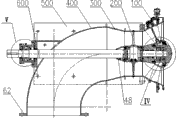
Converge to water guider for ease of the circulating water backwater, form state of aggregation, thus make full use of water can, the diameter of said stator outer shroud convergent near the direction of said rotary wheel device; Simultaneously, flow out the diameter of said transition tube flaring on away from the direction of said rotary wheel device for ease of circulating water.
Be to guarantee the dynamic balancing and the static balancing of runner bucket, avoid welding and cause imbalance and produce bigger vibrations and noise, be welded with first tie-plate on the said main shaft; Said first tie-plate is fixedly connected with said web through second bolt; Be welded with second tie-plate on the said minor axis; Said second tie-plate is fixedly connected with said web through the 3rd bolt.
Preferable, the place, mating face of said first tie-plate and said web has been disposed radially first straight pin; The place, mating face of said second tie-plate and said web has been disposed radially second straight pin; The outside of said second tie-plate is fixedly connected with wearing plate, facing plate.
Preferable, the outside of said first tie-plate is fixedly connected with draft cone; Ring is fixedly connected with sealing seat near said rotary wheel device one side in the said stator; Said minor axis passes said sealing seat; Be provided with the seal ring and first seal ring between said minor axis and the said sealing seat.
Preferable, the root of said runner bucket is set to step-like, and the convexity of this step embeds and is arranged in the said embedded groove, and the base portion of this step is along circumferentially being provided with M first screw; The corresponding said first screw place of said web is provided with N second screw; M and N are natural number, and one of them is the natural number greater than 1 at least; Be provided with lock screw in said first screw that aligns and second screw.
Preferable, said runner bucket root is provided with three said first screws, and the interval is 10 ° between each adjacent first screw; Said web is provided with 7 said second screws, and the interval is 15 ° between each adjacent second screw.
Preferable, the ring internal fixation is connected with bearing support in the said stator; Be set side by side with first roller bearing and second roller bearing in the said bearing support; Said minor axis is by said first roller bearing and second roller bearing; Said first roller bearing and second roller bearing through with the clamp ring axially locating of said minor axis screw-thread fit; The outside of said bearing support is fixedly connected with the water shutoff lid.
Preferable, the outside of said body is fixed with bearing box; The outside of said bearing box is fixed with bearing cap; Be arranged at intervals with first thrust-bearing and second thrust-bearing in the said bearing box; Said main shaft stretches out said bearing box and bearing cap, and by said first thrust-bearing and the supporting of second thrust-bearing; Said first thrust-bearing and second thrust-bearing wire ring axially locating through cooperating with said spindle thread; Be provided with the graphite circle between said main shaft and the said body; Be provided with second seal ring between said main shaft and the said bearing box; Be provided with outside framework oil seal between said main shaft and the said bearing cap.
The invention has the beneficial effects as follows: (1) the present invention can adapt to the circulating water under the different operating modes through the angle adjustment to blade, thereby improves the energy conversion efficiency and the run stability of water turbine;
(2) the present invention can regulate the angle of stator and current according to water flow, thereby improves the mistakes water yield of water turbine and to the utilization ratio of water ability;
(3) owing to can circulating water be assembled at the water outlet place, therefore further improved utilization ratio to the water ability.
In a word, the present invention is high to waterpower utilization rate, and energy conversion efficiency is high, and is stable, and reliability is high, easy to maintenance.The more important thing is that the present invention can be installed on the motor cabinet of cooling tower, main shaft is connected with the blower fan power input shaft, rotate, therefore can save motor of the prior art, saving power thereby make water turbine drive blower fan.
Description of drawings
Fig. 1 is the structural representation of the embodiment of the invention.
Fig. 2 is the structural representation of water guider among Fig. 1.
Fig. 3 is that the A of Fig. 2 is to view.
Fig. 4 is the partial enlarged drawing at I place among Fig. 2.
Fig. 5 is the partial enlarged drawing at II place among Fig. 2.
Fig. 6 is the structural representation of rotary wheel device among Fig. 1.
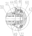
Fig. 7 is the partial enlarged drawing at III place among Fig. 6.
Fig. 8 is the A-A sectional view of Fig. 7.
Fig. 9 is that the B of Fig. 7 is to view.
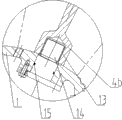
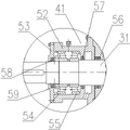
Figure 10 is the partial enlarged drawing at IV place among Fig. 1.
Figure 11 is the partial enlarged drawing at V place among Fig. 1.
Embodiment
Below in conjunction with accompanying drawing and embodiment the present invention is described further:
To shown in Figure 11, a kind of cooling tower special adjustable formula low-pressure water turbine comprises support 500 like Fig. 1, and support 500 is provided with body 600, and end to end water guider 100, rotary wheel device 200, transition tube 300 and draft tube 400.The diameter of transition tube 300 flaring on away from the direction of rotary wheel device 200, the tail end of draft tube 400 is provided with adpting flange 62.
Stator outer shroud 2 is outside equipped with pressure ring 5, and pressure ring 5 is provided with control ring 6.Be fixedly connected with on the pressure ring 5 and each stator connecting plate 10 position and the corresponding connecting plate 11 of quantity, each connecting plate 11 is connected with each stator connecting plate 10 through bearing 12.
Stator outer shroud 2 is provided with dial 25, and pressure ring 5 corresponding dials 25 places are provided with pointer 26.
Be provided with Lower shaft sleeve 13 in the lower end 4b of stator bone 4, Lower shaft sleeve 13 internal clearances are combined with coupling shaft 14, and coupling shaft 14 encircles 1 interference fit simultaneously with in the stator.Be provided with first seal ring 15 between the ring 1 in coupling shaft 14 and the stator.
Corresponding each stator bone 4 place of stator outer shroud 2 are provided with and regulate seat 16, regulate seat 16 and be connected with stator sleeve 17 through bolt, stator sleeve 17 with regulate 16 between be provided with second seal ring 21.
Be provided with Upper shaft sleeve 18 in the stator sleeve 17, stator bone 4 and Upper shaft sleeve 18 Spielpassung.The roof anchorage of stator sleeve 17 is connected with sealing cover 24, is provided with the 3rd seal ring 19 between sealing cover 24 and the stator sleeve 17.Stator bone 4 passes stator sleeve 17 and is connected with guide vane lever 8 with sealing cover 24, and the roof anchorage of guide vane lever 8 is connected with stator end cap 20.
Be provided with clamping ring 29 in the inner chamber 27a of web 27.Web 27 corresponding runner buckets 28 places are provided with circular embedded groove 30, and runner bucket 28 embeds and is arranged in the embedded groove 30, and is fixedly connected through first bolt 34 with hold-down ring 29.
Being welded with first tie-plate, 33, the first tie-plates 33 on the main shaft 31 is fixedly connected with web 27 through second bolt 35; Being welded with second tie-plate, 36, the second tie-plates 36 on the minor axis 32 is fixedly connected with web 27 through the 3rd bolt 37.
The outside that the place, mating face that the place, mating face of first tie-plate 33 and web 27 has been disposed radially first straight pin, 38, the second tie-plates 36 and web 27 has been disposed radially second straight pin, 39, the second tie-plates 10 is fixedly connected with wearing plate, facing plate 40.
The outside of first tie-plate 33 is fixedly connected with draft cone 48, and ring 1 is fixedly connected with sealing seat 49 near rotary wheel device 200 1 sides in the stator.Minor axis 32 passes sealing seat 49, and is provided with the 4th seal ring 50 and first seal ring 51 between minor axis 32 and the sealing seat 49.
The root 28a of runner bucket is set to step-like; The protruding 28a1 of this step embeds and is arranged in the embedded groove 30; The base portion 28a2 of this step is along first screw 41 that circumferentially is provided with 10 ° at 3 intervals; Web 27 corresponding first screws 41 places are provided with second screw 42 at 15 ° at 7 intervals, are provided with lock screw 43 in first screw 41 that aligns and second screw 42.
Since the 41 10 ° of settings at interval of first screw, the 42 15 ° of settings at interval of second screw, and therefore in runner bucket 28 and web 27 counterrotating processes, every interval just has a point of adjustment for 5 °, can select suitable point of adjustment according to concrete operating mode.
In other embodiments, the quantity of first screw and second screw can be the arbitrary natural number greater than 1, to reach essentially identical technique effect.
Ring 1 internal fixation is connected with bearing support 44 in the stator, is set side by side with first roller bearing 45 and second roller bearing 46 in the bearing support 44.Minor axis 32 is by first roller bearing 45 and 46 supportings of second roller bearing.First roller bearing 45 and second roller bearing 46 through with clamp ring 60 axially locating of minor axis 32 screw-thread fit.The outside of bearing support 44 is fixedly connected with water shutoff lid 47.
The outside of body 600 is fixed with bearing box 52, and the outside of bearing box 52 is fixed with bearing cap 53.Be arranged at intervals with first thrust-bearing 54 and second thrust-bearing 55 in the bearing box 52.Main shaft 31 stretches out bearing box 52 and bearing cap 53, and by first thrust-bearing 54 and 55 supportings of second thrust-bearing.First thrust-bearing 52 and second thrust-bearing 54 through with wire ring 59 axially locating of main shaft 31 screw-thread fit.
Be provided with graphite circle 56 between main shaft 31 and the body 600, thereby stop press water to get in the bearing box 52.
Be provided with second seal ring 57 between main shaft 31 and the bearing box 52, thereby prevent that further press water from getting in the bearing box 52.Simultaneously, second seal ring 57 can also seal the lubricant oil in first thrust-bearing and second thrust-bearing.
Be provided with outside framework oil seal 58 between main shaft 31 and the bearing cap 53, to seal the lubricant oil in first thrust-bearing and second thrust-bearing.
The support 500 of water turbine is installed in the former motor of cooling tower place, main shaft 31 is connected with the power input shaft of blower fan; Water guider is connected with first slip joint, connect second slip joint at adpting flange 62 places of draft tube.One bypass is set on the water pipe of cooling tower, makes the circulating water of cooling tower can pass through the water intake 22 that first slip joint flows into water guider.This bypass circuit water throws switch after the wheel apparatus acting completion; Reduce through the processing of draft cone 48 to get into draft tube 400 after the unfavorable factor of turbulent flow and cavitation erosion; Flow into the former of cooling tower once more through second slip joint then and establish in the pipeline, thereby make the water distribution of cooling tower or spray effect constant.
Water turbine when work, flow into the water outlet 23 of flowing through from water intake 22 from the circulating water of cooling tower; Since on water (flow) direction, the tapered diameter of stator outer shroud, thus constitute coniform; Therefore circulating water will become the state of gathering to get into water turbine; Drive runner bucket 28 and rotate, thereby drive main shaft 31 rotations, and then drive the power input shaft motion of blower fan.
According to the flow of circulating water, can regulate the angle of stator and water (flow) direction as required, thus the mistake water yield of decision water guider and to the utilization ratio of water.Concrete regulating method is: control ring 6 is connected with the piston rod of oil hydraulic cylinder, through the flexible drive control ring 6 of piston rod, thereby makes pressure ring 5 clockwise or rotate counterclockwise; After making connecting plate 11 regulate pivot angle then through break pin 9; Power is delivered on the guide vane lever 8, because straight pin 7 is connected to an integral body with guide vane lever 8 and stator bone, therefore; Torsion will be delivered on the stator; Stator is rotated, always keep best angle between stator and the water (flow) direction thereby make, to give full play to the efficient of water turbine.When regulating stator, can conveniently read the adjusting angle of stator through pointer and dial.
According to the flow of circulating water,, can regulate the runner bucket angle of rotary wheel device as required for guaranteeing the normal operation of water turbine.Regulating method is: take off slotted countersunk flat head screw 61, unload wearing plate, facing plate 40, turn on the 3rd bolt 37, minor axis 32 is together pulled down together with second tie-plate 36.Take off lock screw 43, turn on first bolt 34, unload clamping ring 29, rotating wheel blade 28 is to desirable position.With first bolt 34 clamping ring 29 is linked on the runner bucket 28 then, loaded onto lock screw 43, minor axis 28 is reinstated the 3rd bolt 37 together with second tie-plate 36 1 be installed on the web 27, cover wearing plate, facing plate 40, tighten sunk screw 61, regulate and accomplish.
More than describe preferred embodiment of the present invention in detail.Should be appreciated that those of ordinary skill in the art need not creative work and just can design according to the present invention make many modifications and variation.Therefore, all technician in the art all should be in the determined protection domain by claims under this invention's idea on the basis of existing technology through the available technological scheme of logical analysis, reasoning, or a limited experiment.
Claims (10)
1. a cooling tower special adjustable formula low-pressure water turbine comprises support (500); Said support (500) is provided with body (600), and end to end water guider (100), rotary wheel device (200), transition tube (300) and draft tube (400);
Said water guider (100) comprises ring (1) and stator outer shroud (2) in the stator; Ring (1) along the circumferential direction is provided with a circle stator in the said stator; Said stator comprises the guide vane (3) and the stator bone (4) of one;
Said rotary wheel device (200) comprises web (27); Said web (27) is provided with runner bucket (28);
It is characterized in that:
The upper end (4a) of said stator bone (4) passes said stator outer shroud (2), and stator bone upper end (4a) is connected with guide vane lever (8) through straight pin (7); Said guide vane lever (8) is connected with stator connecting plate (10) through break pin (9);
Said stator outer shroud (2) is outside equipped with pressure ring (5); Said pressure ring (5) is provided with control ring (6); Be fixedly connected with on the said pressure ring (5) and each said stator connecting plate (10) position and the corresponding connecting plate of quantity (11); Each said connecting plate (11) is connected with each said stator connecting plate (10) through bearing (12);
Be provided with Lower shaft sleeve (13) in the lower end (4b) of said stator bone (4); Said Lower shaft sleeve (13) internal clearance is combined with coupling shaft (14); Said coupling shaft (14) encircles (1) interference fit simultaneously with in the said stator;
The both sides of said web (27) are connected with main shaft (31) and minor axis (32) respectively; Said main shaft (31) passes said draft tube (400);
Be provided with clamping ring (29) in the inner chamber (27a) of said web (27); The corresponding said runner bucket of said web (27) (28) locates to be provided with circular embedded groove (30); Said runner bucket (28) embeds and is arranged in the said embedded groove (30), and is fixedly connected through first bolt (34) with said hold-down ring (29);
The tail end of said draft tube (400) is provided with adpting flange (62).
2. cooling tower special adjustable formula low-pressure water turbine as claimed in claim 1 is characterized in that: be provided with first seal ring (15) between the ring (1) in said coupling shaft (14) and the said stator;
Corresponding each the said stator bone (4) of said stator outer shroud (2) locates to be provided with adjusting seat (16); Said adjusting seat (16) connects stator sleeve (17) through bolt; Be provided with second seal ring (21) between said stator sleeve (17) and the said adjusting seat (16);
Be provided with Upper shaft sleeve (18) in the said stator sleeve (17); Said stator bone (4) and said Upper shaft sleeve (18) Spielpassung; The roof anchorage of said stator sleeve (17) is connected with sealing cover (24); Be provided with the 3rd seal ring (19) between said sealing cover (24) and the said stator sleeve (17); Said stator bone (4) passes said stator sleeve (17) and is connected with said guide vane lever (8) with sealing cover (24); The roof anchorage of said guide vane lever (8) is connected with stator end cap (20).
3. cooling tower special adjustable formula low-pressure water turbine as claimed in claim 1 is characterized in that: the diameter of said stator outer shroud (2) convergent near the direction of said rotary wheel device (200); The diameter of said transition tube (300) flaring on away from the direction of said rotary wheel device (200).
4. cooling tower special adjustable formula low-pressure water turbine as claimed in claim 1 is characterized in that: be welded with first tie-plate (33) on the said main shaft (31); Said first tie-plate (33) is fixedly connected with said web (27) through second bolt (35); Be welded with second tie-plate (36) on the said minor axis (32); Said second tie-plate (36) is fixedly connected with said web (27) through the 3rd bolt (37).
5. cooling tower special adjustable formula low-pressure water turbine as claimed in claim 4 is characterized in that: said first tie-plate (33) has been disposed radially first straight pin (38) with the place, mating face of said web (27); Said second tie-plate (36) has been disposed radially second straight pin (39) with the place, mating face of said web (27); The outside of said second tie-plate (36) is fixedly connected with wearing plate, facing plate (40).
6. like claim 4 or 5 described cooling tower special adjustable formula low-pressure water turbines, it is characterized in that: the outside of said first tie-plate (33) is fixedly connected with draft cone (48); Ring (1) is fixedly connected with sealing seat (49) near said rotary wheel device (200) one sides in the said stator; Said minor axis (32) passes said sealing seat (49); Be provided with the 4th seal ring (50) and first seal ring (51) between said minor axis (32) and the said sealing seat (49).
7. cooling tower special adjustable formula low-pressure water turbine as claimed in claim 1; It is characterized in that: the root of said runner bucket (28a) is set to step-like; The convexity of this step (28a1) embeds and is arranged in the said embedded groove (30), and the base portion of this step (28a2) is along circumferentially being provided with M first screw (41); Corresponding said first screw of said web (27) (41) locates to be provided with N second screw (42); M and N are natural number, and one of them is the natural number greater than 1 at least; Be provided with lock screw (43) in said first screw (41) that aligns and second screw (42).
8. the adjustable runner of cooling tower dedicated water turbine as claimed in claim 7, it is characterized in that: said runner bucket root (28a) is provided with three said first screws (41), and the interval is 10 ° between each adjacent first screw (41); Said web (26) is provided with 7 said second screws (42), and the interval is 15 ° between each adjacent second screw (42).
9. like claim 1,2,3,4,5, the adjustable runner of 7 or 8 arbitrary described cooling tower dedicated water turbines, it is characterized in that: ring (1) internal fixation is connected with bearing support (44) in the said stator; Be set side by side with first roller bearing (45) and second roller bearing (46) in the said bearing support (44); Said minor axis (32) is by said first roller bearing (45) and second roller bearing (46) supporting; Said first roller bearing (45) and second roller bearing (46) through with clamp ring (60) axially locating of said minor axis (32) screw-thread fit; The outside of said bearing support (44) is fixedly connected with water shutoff lid (47).
10. like claim 1,2,3,4,5, the adjustable runner of 7 or 8 arbitrary described cooling tower dedicated water turbines, it is characterized in that: the outside of said body (600) is fixed with bearing box (52); The outside of said bearing box (52) is fixed with bearing cap (53); Be arranged at intervals with first thrust-bearing (54) and second thrust-bearing (55) in the said bearing box (52); Said main shaft (31) stretches out said bearing box (52) and bearing cap (53), and by said first thrust-bearing (54) and second thrust-bearing (55) supporting; Said first thrust-bearing (54) and second thrust-bearing (55) through with wire ring (59) axially locating of said main shaft (31) screw-thread fit; Be provided with graphite circle (56) between said main shaft (31) and the said body (600); Be provided with second seal ring (57) between said main shaft (31) and the said bearing box (52); Be provided with outside framework oil seal (58) between said main shaft (31) and the said bearing cap (53).
Priority Applications (1)
| Application Number | Priority Date | Filing Date | Title |
|---|---|---|---|
| CN2012101103186A CN102606374A (en) | 2012-04-16 | 2012-04-16 | Adjustable low-pressure water turbine special for cooling tower |
Applications Claiming Priority (1)
| Application Number | Priority Date | Filing Date | Title |
|---|---|---|---|
| CN2012101103186A CN102606374A (en) | 2012-04-16 | 2012-04-16 | Adjustable low-pressure water turbine special for cooling tower |
Publications (1)
| Publication Number | Publication Date |
|---|---|
| CN102606374A true CN102606374A (en) | 2012-07-25 |
Family
ID=46524058
Family Applications (1)
| Application Number | Title | Priority Date | Filing Date |
|---|---|---|---|
| CN2012101103186A Pending CN102606374A (en) | 2012-04-16 | 2012-04-16 | Adjustable low-pressure water turbine special for cooling tower |
Country Status (1)
| Country | Link |
|---|---|
| CN (1) | CN102606374A (en) |
Cited By (6)
| Publication number | Priority date | Publication date | Assignee | Title |
|---|---|---|---|---|
| CN104179625A (en) * | 2014-07-31 | 2014-12-03 | 河海大学 | Straight-pipe ultramicro water turbine |
| CN105604771A (en) * | 2016-03-16 | 2016-05-25 | 乐山东方动力节能设备有限公司 | Packaged energy recycling device of sewage treatment plant |
| CN105804913A (en) * | 2016-04-11 | 2016-07-27 | 武汉大学 | Adjusting method and device for pump serving as water turbine |
| CN106194550A (en) * | 2016-08-12 | 2016-12-07 | 杭州诚德发电设备有限公司 | Adjustable runner hydraulic turbine installation method |
| CN106662065A (en) * | 2014-04-16 | 2017-05-10 | 富兰克林帝国有限公司 | Submersible electrical wicket gates operator |
| CN107313889A (en) * | 2017-05-27 | 2017-11-03 | 杨广平 | Vertical self-contained conduit type hydroelectric generating group |
Citations (13)
| Publication number | Priority date | Publication date | Assignee | Title |
|---|---|---|---|---|
| GB172649A (en) * | 1920-12-10 | 1922-07-13 | Ignaz Storek | Improvements in or relating to water-turbine wheels with adjustable blades |
| GB205490A (en) * | 1922-04-15 | 1924-06-05 | Lewis Ferry Moody | Improvements in runners for turbines and pumps |
| US2870848A (en) * | 1954-04-13 | 1959-01-27 | Liaaen Nils Johannes | Pitch adjusting gear for controllable pitch propellers |
| US4639190A (en) * | 1984-05-16 | 1987-01-27 | Hitachi, Ltd. | Tubular water wheel |
| RU2094647C1 (en) * | 1996-06-28 | 1997-10-27 | Научно-производственное объединение "Винт" | Hydraulic-turbine adjustable-blade runner |
| RU2213880C2 (en) * | 2001-09-04 | 2003-10-10 | Панарин Юрий Викторович | Hydraulic turbine wheel |
| CN1888413A (en) * | 2006-07-25 | 2007-01-03 | 四川东风电机厂有限公司 | Through-flow type machine set water guiding mechanism |
| CN201090352Y (en) * | 2007-08-29 | 2008-07-23 | 浙江金轮机电实业有限公司 | Interior ring assembly of hydraulic turbine taper water distributor |
| CN201326502Y (en) * | 2008-12-26 | 2009-10-14 | 安维民 | Energy-saving special water motor of cooling tower |
| CN201461197U (en) * | 2009-05-11 | 2010-05-12 | 中国水利水电第五工程局有限公司 | Guide vane transmission mechanism of hydroelectric station machine set |
| CN201934242U (en) * | 2011-01-29 | 2011-08-17 | 浙江金轮机电实业有限公司 | Outer ring for water guide mechanism of water turbine |
| CN202132165U (en) * | 2011-01-24 | 2012-02-01 | 杭州力源发电设备有限公司 | Water turbine water guide mechanism protecting device of shear pin and friction device |
| CN202140224U (en) * | 2011-07-12 | 2012-02-08 | 上海福伊特水电设备有限公司 | Friction braking device for water turbine movable guide vane |
-
2012
- 2012-04-16 CN CN2012101103186A patent/CN102606374A/en active Pending
Patent Citations (13)
| Publication number | Priority date | Publication date | Assignee | Title |
|---|---|---|---|---|
| GB172649A (en) * | 1920-12-10 | 1922-07-13 | Ignaz Storek | Improvements in or relating to water-turbine wheels with adjustable blades |
| GB205490A (en) * | 1922-04-15 | 1924-06-05 | Lewis Ferry Moody | Improvements in runners for turbines and pumps |
| US2870848A (en) * | 1954-04-13 | 1959-01-27 | Liaaen Nils Johannes | Pitch adjusting gear for controllable pitch propellers |
| US4639190A (en) * | 1984-05-16 | 1987-01-27 | Hitachi, Ltd. | Tubular water wheel |
| RU2094647C1 (en) * | 1996-06-28 | 1997-10-27 | Научно-производственное объединение "Винт" | Hydraulic-turbine adjustable-blade runner |
| RU2213880C2 (en) * | 2001-09-04 | 2003-10-10 | Панарин Юрий Викторович | Hydraulic turbine wheel |
| CN1888413A (en) * | 2006-07-25 | 2007-01-03 | 四川东风电机厂有限公司 | Through-flow type machine set water guiding mechanism |
| CN201090352Y (en) * | 2007-08-29 | 2008-07-23 | 浙江金轮机电实业有限公司 | Interior ring assembly of hydraulic turbine taper water distributor |
| CN201326502Y (en) * | 2008-12-26 | 2009-10-14 | 安维民 | Energy-saving special water motor of cooling tower |
| CN201461197U (en) * | 2009-05-11 | 2010-05-12 | 中国水利水电第五工程局有限公司 | Guide vane transmission mechanism of hydroelectric station machine set |
| CN202132165U (en) * | 2011-01-24 | 2012-02-01 | 杭州力源发电设备有限公司 | Water turbine water guide mechanism protecting device of shear pin and friction device |
| CN201934242U (en) * | 2011-01-29 | 2011-08-17 | 浙江金轮机电实业有限公司 | Outer ring for water guide mechanism of water turbine |
| CN202140224U (en) * | 2011-07-12 | 2012-02-08 | 上海福伊特水电设备有限公司 | Friction braking device for water turbine movable guide vane |
Cited By (9)
| Publication number | Priority date | Publication date | Assignee | Title |
|---|---|---|---|---|
| CN106662065A (en) * | 2014-04-16 | 2017-05-10 | 富兰克林帝国有限公司 | Submersible electrical wicket gates operator |
| CN106662065B (en) * | 2014-04-16 | 2019-08-02 | 富兰克林帝国有限公司 | A kind of underwater electronic guide vane operating device |
| CN104179625A (en) * | 2014-07-31 | 2014-12-03 | 河海大学 | Straight-pipe ultramicro water turbine |
| CN105604771A (en) * | 2016-03-16 | 2016-05-25 | 乐山东方动力节能设备有限公司 | Packaged energy recycling device of sewage treatment plant |
| CN105804913A (en) * | 2016-04-11 | 2016-07-27 | 武汉大学 | Adjusting method and device for pump serving as water turbine |
| CN106194550A (en) * | 2016-08-12 | 2016-12-07 | 杭州诚德发电设备有限公司 | Adjustable runner hydraulic turbine installation method |
| CN106194550B (en) * | 2016-08-12 | 2018-12-25 | 杭州诚德发电设备有限公司 | Adjustable runner hydraulic turbine installation method |
| CN107313889A (en) * | 2017-05-27 | 2017-11-03 | 杨广平 | Vertical self-contained conduit type hydroelectric generating group |
| CN107313889B (en) * | 2017-05-27 | 2019-05-31 | 杨广平 | Vertical self-contained conduit type hydroelectric generating group |
Similar Documents
| Publication | Publication Date | Title |
|---|---|---|
| CN102606374A (en) | Adjustable low-pressure water turbine special for cooling tower | |
| US20190071992A1 (en) | Generalized frequency conversion system for steam turbine generator unit | |
| CN101482083B (en) | Ultra-low specific speed mixed-flow type turbine | |
| WO2010117621A3 (en) | In-pipe hydro-electric power system and turbine | |
| CN103557186A (en) | Adjustable axial flow pump with front guide vanes | |
| CN104196579B (en) | A kind of exhaust-gas turbocharger system with three grades of adjustable nozzles | |
| CN108590920A (en) | A kind of hydraulic turbine installation | |
| CN203067362U (en) | Tubular pump with adjustable inflow angle of back guide vane | |
| CN107100677A (en) | A kind of nozzle ring assemblies of fixed blade and adjustable vane combination | |
| CN104141580A (en) | Straight flow turbine | |
| CN202579011U (en) | Adjustable water guide device of dedicated water turbine for cooling tower | |
| CN205478081U (en) | Mixed -flow hydroelectric set | |
| CN104405457B (en) | A kind of energy gradient utilization system of back pressure turbine heat supply | |
| CN102606366B (en) | Special built-in cantilever type water turbine for cooling tower | |
| CN110630529A (en) | Inlet pre-rotation adjusting device based on mixed flow pump flow tracking and adjusting method thereof | |
| CN202228133U (en) | Steam turbine nozzle | |
| CN204238990U (en) | A kind of energy gradient utilization system of back pressure turbine heat supply | |
| CN107313889B (en) | Vertical self-contained conduit type hydroelectric generating group | |
| CN205383033U (en) | Cylindrical valve axial flow turbine | |
| CN113915042A (en) | Guide vane body structure of water turbine and mounting method thereof | |
| CN208669358U (en) | Compact little volume flow high pressure ratio mixed-flow industrial turbine | |
| CN207777062U (en) | A kind of integral type hydraulic turbine automatic flow rate adjusting device | |
| BG113168A (en) | Water conservation power plant with controlled suction head | |
| CN201242363Y (en) | Multifunctional water wheel type cooling device | |
| CN210859034U (en) | Pipeline type hydroelectric generating set |
Legal Events
| Date | Code | Title | Description |
|---|---|---|---|
| C06 | Publication | ||
| PB01 | Publication | ||
| C10 | Entry into substantive examination | ||
| SE01 | Entry into force of request for substantive examination | ||
| C12 | Rejection of a patent application after its publication | ||
| RJ01 | Rejection of invention patent application after publication |
Application publication date: 20120725 |