CN102486051A - Manual demolishing method of large-area spherical net rack - Google Patents
Manual demolishing method of large-area spherical net rack Download PDFInfo
- Publication number
- CN102486051A CN102486051A CN2010105743784A CN201010574378A CN102486051A CN 102486051 A CN102486051 A CN 102486051A CN 2010105743784 A CN2010105743784 A CN 2010105743784A CN 201010574378 A CN201010574378 A CN 201010574378A CN 102486051 A CN102486051 A CN 102486051A
- Authority
- CN
- China
- Prior art keywords
- spherical net
- net brace
- unit
- remove
- spherical
- Prior art date
- Legal status (The legal status is an assumption and is not a legal conclusion. Google has not performed a legal analysis and makes no representation as to the accuracy of the status listed.)
- Granted
Links
Images

Abstract
The invention relates to a manual demolishing method of a large-area spherical net rack. The method comprises the steps of: 1) setting spherical net rack demolishing units according to load capacity; 2) demolishing a first spherical net rack demolishing unit, installing supporting welded pipes, and driving iron wedges between the lower ends of the supporting welded pipes and the ground, wherein the upper ends of the supporting welded pipes are welded with the lower parts of supporting balls on the spherical net rack; 3) establishing an operating platform, erecting a holding pole on the first spherical net rack demolishing unit, setting a hoist on the ground and enabling the hoist to hold the first spherical net rack demolishing unit through lifting hooks on the holding pole; 4) cutting the first spherical net rack demolishing unit for disintegration; and 5) repeating the step (2) to the step (4) till the entire spherical net rack is fully demolished. The manual demolishing method of the large-area spherical net rack has the advantages that a larges crane is not required to be used, a jacking rack is not required to be installed, the construction cost is reduced, the construction time is shortened and the construction efficiency and the economic benefit are improved. The manual demolishing method of the large-area spherical net rack is a safe and reliable manual demolishing method for the large-area spherical net rack.
Description
Technical field
The present invention relates to spherical net brace and remove the field, the artificial method for dismounting of especially a kind of large tracts of land spherical net brace.
Background technology
The ball-type rack is a kind of building structure commonly used, and operated by rotary motion is on the building roof, and the ball-type space truss structure is simple; Comprise and winding up and lower edge, be steel pipe and process that the node that winds up with lower edge is provided with fulcrum ball; Stressed between the member evenly the requirement of beam string structure internal force is rigorous up and down, and globality is strong.Existing ball-type rack method for dismounting mainly relies on large-scale crane or the whole jacking frame that moves; But often remove the place and can not get into large-scale crane and the whole jacking frame that moves; And the duration is pressed for time to lack and sets up the jacking frame time; Large-scale in addition crane gets into construction cost is increased, and has reduced profit margin.
Summary of the invention
The objective of the invention is to overcome the deficiency of prior art, provide a kind of large tracts of land spherical net brace artificial method for dismounting, this method need not to adopt large-scale crane and jacking frame is installed; Safe and reliable; Reduce construction cost, shortened the engineering time, improved efficiency of construction and economic benefit.
The present invention solves its technical problem and realizes through following technical scheme:
The artificial method for dismounting of a kind of large tracts of land spherical net brace comprises hoist engine and pole, its step:
⑴ set out spherical net brace dismounting unit according to the load capacity of hoist engine and pole;
⑵ remove first spherical net brace and remove the unit; Remove the unit and the spherical net brace that is adjacent is removed to install below the unit and supported welded tube at first spherical net brace; This supports the welded tube upper end and welds with the fulcrum ball bottom on the spherical net brace; Between this support welded tube lower end and ground, squeeze into the iron wedge, guarantee to support welded tube and reach stressed;
⑶ set up operating platform on first spherical net brace is removed the lower edge of unit or winded up, remove on the unit at first spherical net brace and set up pole, on ground hoist engine is set, and makes hoist engine hang first spherical net brace through the suspension hook on the pole and remove the unit;
⑷ cut first spherical net brace and remove the unit; Cutting first spherical net brace is removed winding up of unit earlier; Cut first spherical net brace again and remove the lower edge of unit, will lift ground through hoist engine from first spherical net brace dismounting unit that spherical net brace cuts down and disintegrate;
⑸ remove the unit to second spherical net brace and remove, and repeating step ⑵-⑷ is until with whole spherical net brace complete removal.
And the diameter of described support welded tube is 150mm, and this support welded tube moves to the fulcrum ball bottom through the jack that is installed on the spherical net brace.
And described operating platform is two-layer, and one deck is arranged on the spherical net brace position of winding up, and one deck is arranged on spherical net brace lower edge position, and operating platform adopts the 50mm plank, lays width 400mm, and plank is fixed with scaffold employing galvanized wire 12#.
And described the dismounting on the unit at adjacent spherical net brace installed spirit level, whenever at a distance from 2 h observation once.
Advantage of the present invention and beneficial effect are:
1, the artificial method for dismounting employing of this large tracts of land spherical net brace equipment is hoist engine and pole, and equipment is little, and cost of use is low, and high efficiency has been saved the construction equipment cost.
2, the artificial method for dismounting of this large tracts of land spherical net brace is removed first spherical net brace and is removed the unit; Remove the unit and the spherical net brace that is adjacent is removed to install below the unit and supported welded tube at first spherical net brace; This supports the welded tube upper end and welds with the fulcrum ball bottom on the spherical net brace; Between this support welded tube lower end and ground, squeeze into the iron wedge, guarantee to support welded tube and reach stressed, this kind mode has improved the safety of removing spherical net brace; Prevent that spherical net brace from owing to unbalance stress caves in, having ensured construction quality.
3, the present invention need not to adopt large-scale crane and jacking frame is installed, and has reduced construction cost, has shortened the engineering time, has improved efficiency of construction and economic benefit, is the artificial method for dismounting of a kind of safe and reliable large tracts of land spherical net brace.
Description of drawings
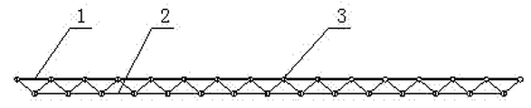
Fig. 1 is the front view of spherical net brace;
Fig. 2 is Fig. 1 vertical view;
Fig. 3 is a spherical net brace part dismounting structure sketch map.
The specific embodiment
Through specific embodiment the present invention is made further detailed description below, following examples are descriptive, are not determinate, can not limit protection scope of the present invention with this.
The artificial method for dismounting of a kind of large tracts of land spherical net brace, this spherical net brace comprise wind up 1, lower edge 2 and fulcrum ball 3, comprise hoist engine 11, this hoist engine rated weight can be at 0.5 ton, pole 5 and scaffold 7 the steps include:
⑴ set out spherical net brace dismounting unit according to the load capacity of hoist engine and pole, and definite cut point 6;
⑵ remove first spherical net brace and remove unit 10; Remove the unit and the spherical net brace that is adjacent is removed to install below the unit 4 and supported welded tube 9 at first spherical net brace; This supports the welded tube upper end and welds with the fulcrum ball bottom on the spherical net brace, between this support welded tube lower end and ground, squeezes into the iron wedge, guarantees to support welded tube and reaches stressed; The diameter that supports welded tube is 150mm, and this support welded tube moves to the fulcrum ball bottom through the jack that is installed on the spherical net brace;
⑶ set up operating platform 8 on first spherical net brace is removed the lower edge of unit or winded up, operating platform is two-layer, and one deck is arranged on the spherical net brace position of winding up; One deck is arranged on spherical net brace lower edge position, and operating platform adopts the 50mm plank, lays width 400mm; Plank and scaffold adopt galvanized wire 12# to fix, and this operating platform can also be provided with multiple tracks, remove on the unit at first spherical net brace and set up pole; On ground hoist engine is set, makes hoist engine hang first spherical net brace and remove the unit, remove on the unit at adjacent spherical net brace spirit level is installed through the suspension hook on the pole; Whenever once at a distance from 2 h observation; Whether the inspection rack has distortion, prevents in demolishing process because of old rack individual elements system components damagedly, causes landslide;
⑷ cut first spherical net brace and remove the unit; Cutting first spherical net brace is removed winding up of unit earlier; Cut first spherical net brace again and remove the lower edge of unit, will lift ground through hoist engine from first spherical net brace dismounting unit that spherical net brace cuts down and disintegrate;
⑸ remove the unit to second spherical net brace and remove, and repeating step ⑵-⑷ is until with whole spherical net brace complete removal.
Claims (4)
1. the artificial method for dismounting of large tracts of land spherical net brace comprises hoist engine and pole, and it is characterized in that: this method comprises the steps:
⑴ set out spherical net brace dismounting unit according to the load capacity of hoist engine and pole;
⑵ remove first spherical net brace and remove the unit; Remove the unit and the spherical net brace that is adjacent is removed to install below the unit and supported welded tube at first spherical net brace; This supports the welded tube upper end and welds with the fulcrum ball bottom on the spherical net brace; Between this support welded tube lower end and ground, squeeze into the iron wedge, guarantee to support welded tube and reach stressed;
⑶ set up operating platform on first spherical net brace is removed the lower edge of unit or winded up, remove on the unit at first spherical net brace and set up pole, on ground hoist engine is set, and makes hoist engine hang first spherical net brace through the suspension hook on the pole and remove the unit;
⑷ cut first spherical net brace and remove the unit; Cutting first spherical net brace is removed winding up of unit earlier; Cut first spherical net brace again and remove the lower edge of unit, will lift ground through hoist engine from first spherical net brace dismounting unit that spherical net brace cuts down and disintegrate;
⑸ remove the unit to second spherical net brace and remove, and repeating step ⑵-⑷ is until with whole spherical net brace complete removal.
2. the artificial method for dismounting of large tracts of land spherical net brace according to claim 1, it is characterized in that: the diameter of described support welded tube is 150mm, this support welded tube moves to the fulcrum ball bottom through the jack that is installed on the spherical net brace.
3. the artificial method for dismounting of large tracts of land spherical net brace according to claim 1; It is characterized in that: described operating platform is two-layer; One deck is arranged on the spherical net brace position of winding up, and one deck is arranged on spherical net brace lower edge position, and operating platform adopts the 50mm plank; Lay width 400mm, plank and scaffold adopt galvanized wire 12# to fix.
4. the artificial method for dismounting of large tracts of land spherical net brace according to claim 1 is characterized in that: the described dismounting on the unit at adjacent spherical net brace installed spirit level, whenever at a distance from 2 h observation once.
Priority Applications (1)
| Application Number | Priority Date | Filing Date | Title |
|---|---|---|---|
| CN2010105743784A CN102486051B (en) | 2010-12-06 | 2010-12-06 | Manual demolishing method of large-area spherical net rack |
Applications Claiming Priority (1)
| Application Number | Priority Date | Filing Date | Title |
|---|---|---|---|
| CN2010105743784A CN102486051B (en) | 2010-12-06 | 2010-12-06 | Manual demolishing method of large-area spherical net rack |
Publications (2)
| Publication Number | Publication Date |
|---|---|
| CN102486051A true CN102486051A (en) | 2012-06-06 |
| CN102486051B CN102486051B (en) | 2013-12-11 |
Family
ID=46151617
Family Applications (1)
| Application Number | Title | Priority Date | Filing Date |
|---|---|---|---|
| CN2010105743784A Active CN102486051B (en) | 2010-12-06 | 2010-12-06 | Manual demolishing method of large-area spherical net rack |
Country Status (1)
| Country | Link |
|---|---|
| CN (1) | CN102486051B (en) |
Cited By (6)
| Publication number | Priority date | Publication date | Assignee | Title |
|---|---|---|---|---|
| CN103866992A (en) * | 2012-12-18 | 2014-06-18 | 上海建工五建集团有限公司 | Method for renovating ceiling of net rack |
| CN109538921A (en) * | 2018-11-20 | 2019-03-29 | 中国三冶集团有限公司 | Gas chamber piston system hangs method for dismounting under a kind of accident condition |
| WO2021120687A1 (en) * | 2019-12-19 | 2021-06-24 | 中建科工集团有限公司 | Method for entire removal of space truss and assistive support mechanism |
| CN113123635A (en) * | 2021-04-07 | 2021-07-16 | 中国建筑第八工程局有限公司 | Protective dismantling construction method for single truss of net rack structure ring support |
| WO2023226256A1 (en) * | 2022-05-23 | 2023-11-30 | 中建钢构工程有限公司 | Grid frame demolition method |
| CN117266627A (en) * | 2023-11-23 | 2023-12-22 | 北京市第三建筑工程有限公司 | Method for dismantling high-altitude large-span roof truss |
Citations (8)
| Publication number | Priority date | Publication date | Assignee | Title |
|---|---|---|---|---|
| JPH06272403A (en) * | 1993-03-19 | 1994-09-27 | Shimizu Corp | Construction method for demolishing building |
| CN2270772Y (en) * | 1996-11-11 | 1997-12-17 | 周建平 | Lattice framed structure integral lifting device |
| JP3108734B2 (en) * | 1996-05-23 | 2000-11-13 | 五洋建設株式会社 | Demolition of temporary roof |
| JP2002235446A (en) * | 2001-02-07 | 2002-08-23 | Ohbayashi Corp | Demolition method of building |
| JP3834325B2 (en) * | 2004-07-07 | 2006-10-18 | 株式会社竹中工務店 | Building demolition method |
| CN101280630A (en) * | 2008-05-20 | 2008-10-08 | 冯贵法 | Network frame house cap integral lifting construction method |
| CN201193404Y (en) * | 2008-05-20 | 2009-02-11 | 冯贵法 | Equipment special for integral lifting construction for network frame house top |
| CN101787795A (en) * | 2010-03-03 | 2010-07-28 | 潮峰钢构集团有限公司 | Large-size net rack suspension cable mounting platform and suspension cable construction method |
-
2010
- 2010-12-06 CN CN2010105743784A patent/CN102486051B/en active Active
Patent Citations (8)
| Publication number | Priority date | Publication date | Assignee | Title |
|---|---|---|---|---|
| JPH06272403A (en) * | 1993-03-19 | 1994-09-27 | Shimizu Corp | Construction method for demolishing building |
| JP3108734B2 (en) * | 1996-05-23 | 2000-11-13 | 五洋建設株式会社 | Demolition of temporary roof |
| CN2270772Y (en) * | 1996-11-11 | 1997-12-17 | 周建平 | Lattice framed structure integral lifting device |
| JP2002235446A (en) * | 2001-02-07 | 2002-08-23 | Ohbayashi Corp | Demolition method of building |
| JP3834325B2 (en) * | 2004-07-07 | 2006-10-18 | 株式会社竹中工務店 | Building demolition method |
| CN101280630A (en) * | 2008-05-20 | 2008-10-08 | 冯贵法 | Network frame house cap integral lifting construction method |
| CN201193404Y (en) * | 2008-05-20 | 2009-02-11 | 冯贵法 | Equipment special for integral lifting construction for network frame house top |
| CN101787795A (en) * | 2010-03-03 | 2010-07-28 | 潮峰钢构集团有限公司 | Large-size net rack suspension cable mounting platform and suspension cable construction method |
Cited By (7)
| Publication number | Priority date | Publication date | Assignee | Title |
|---|---|---|---|---|
| CN103866992A (en) * | 2012-12-18 | 2014-06-18 | 上海建工五建集团有限公司 | Method for renovating ceiling of net rack |
| CN109538921A (en) * | 2018-11-20 | 2019-03-29 | 中国三冶集团有限公司 | Gas chamber piston system hangs method for dismounting under a kind of accident condition |
| WO2021120687A1 (en) * | 2019-12-19 | 2021-06-24 | 中建科工集团有限公司 | Method for entire removal of space truss and assistive support mechanism |
| CN113123635A (en) * | 2021-04-07 | 2021-07-16 | 中国建筑第八工程局有限公司 | Protective dismantling construction method for single truss of net rack structure ring support |
| WO2023226256A1 (en) * | 2022-05-23 | 2023-11-30 | 中建钢构工程有限公司 | Grid frame demolition method |
| CN117266627A (en) * | 2023-11-23 | 2023-12-22 | 北京市第三建筑工程有限公司 | Method for dismantling high-altitude large-span roof truss |
| CN117266627B (en) * | 2023-11-23 | 2024-02-23 | 北京市第三建筑工程有限公司 | Method for dismantling high-altitude large-span roof truss |
Also Published As
| Publication number | Publication date |
|---|---|
| CN102486051B (en) | 2013-12-11 |
Similar Documents
| Publication | Publication Date | Title |
|---|---|---|
| CN204370830U (en) | A kind of electric pole centralizer | |
| CN103061506B (en) | Construction method of steel structure dome | |
| CN102486051B (en) | Manual demolishing method of large-area spherical net rack | |
| CN103643800B (en) | The erection & lift system of buckling-restrained bracing member and construction method thereof | |
| CN106337555A (en) | Method for constructing triangular steel support for cantilever structure of outer wall of building | |
| CN103982045A (en) | Installation construction method of roof lattice shell structure without supports and cantilevers | |
| CN102900021B (en) | Split mounting type bridge wet joint construction method | |
| CN203794498U (en) | Built-in self-elevating tower crane device | |
| CN206692235U (en) | A kind of steel structure dome lifts by crane erecting device | |
| CN205036072U (en) | A shaped steel formwork support that encorbelments for high altitude structure of encorbelmenting | |
| CN110409477B (en) | Steel suspension box anti-surge internal support system and construction method thereof | |
| CN104032678A (en) | H-shaped tower column inner force adjustable temporary cross supporting structure and construction method thereof | |
| CN204644884U (en) | High pier over-form construction reinforced bar installs mobile stock | |
| CN103291116B (en) | For the netted shuttering supporting operating platform of construction of water tank on top of inverted-cone water tower | |
| CN202401769U (en) | Detachable concrete cloth machine for self-elevating creeping formwork system | |
| CN108999394B (en) | Construction process of floor type scaffold rotary cantilever type scaffold | |
| CN102777050A (en) | Assembly type jig frame for longspan pipe truss roof girder | |
| CN205369229U (en) | But walking hoisting frame suitable for manual hole digging pile steel reinforcement cage is laid | |
| CN102425115A (en) | Control method for actively overcoming dead weight and line shape of vice cable saddle buttress concrete | |
| CN203359856U (en) | Support beam structure for external tower crane in high-rise core tube | |
| CN104045014A (en) | Pole arraying frame for pole welding | |
| CN104314354A (en) | High-voltage electric tower base | |
| CN107217912A (en) | It is a kind of to be used for the superelevation physical isolation construction method of neighbouring high ferro Business Line construction | |
| CN209874434U (en) | Simple and easy scaffold frame of encorbelmenting of building high latitude | |
| CN208266866U (en) | A kind of wind resistance steady type guy anchor |
Legal Events
| Date | Code | Title | Description |
|---|---|---|---|
| C06 | Publication | ||
| PB01 | Publication | ||
| C10 | Entry into substantive examination | ||
| SE01 | Entry into force of request for substantive examination | ||
| C14 | Grant of patent or utility model | ||
| GR01 | Patent grant |