CN102472010A - Forming unit and method for producing a material web - Google Patents
Forming unit and method for producing a material web Download PDFInfo
- Publication number
- CN102472010A CN102472010A CN2010800298881A CN201080029888A CN102472010A CN 102472010 A CN102472010 A CN 102472010A CN 2010800298881 A CN2010800298881 A CN 2010800298881A CN 201080029888 A CN201080029888 A CN 201080029888A CN 102472010 A CN102472010 A CN 102472010A
- Authority
- CN
- China
- Prior art keywords
- sieve
- supporting surface
- band
- forming unit
- dehydration
- Prior art date
- Legal status (The legal status is an assumption and is not a legal conclusion. Google has not performed a legal analysis and makes no representation as to the accuracy of the status listed.)
- Granted
Links
Images


Classifications
-
- D—TEXTILES; PAPER
- D21—PAPER-MAKING; PRODUCTION OF CELLULOSE
- D21F—PAPER-MAKING MACHINES; METHODS OF PRODUCING PAPER THEREON
- D21F9/00—Complete machines for making continuous webs of paper
- D21F9/003—Complete machines for making continuous webs of paper of the twin-wire type
-
- D—TEXTILES; PAPER
- D21—PAPER-MAKING; PRODUCTION OF CELLULOSE
- D21F—PAPER-MAKING MACHINES; METHODS OF PRODUCING PAPER THEREON
- D21F1/00—Wet end of machines for making continuous webs of paper
- D21F1/48—Suction apparatus
- D21F1/483—Drainage foils and bars
-
- D—TEXTILES; PAPER
- D21—PAPER-MAKING; PRODUCTION OF CELLULOSE
- D21F—PAPER-MAKING MACHINES; METHODS OF PRODUCING PAPER THEREON
- D21F1/00—Wet end of machines for making continuous webs of paper
- D21F1/48—Suction apparatus
- D21F1/52—Suction boxes without rolls
Abstract
The invention relates to a forming unit (1), in particular a sheet forming unit for use in a machine for producing a material web from a fibrous or nonwoven suspension (FS), comprising at least two endlessly circulating wire belts (2, 3) which are guided over at least a subregion of the circulation path thereof, forming a twin-wire zone (4), a dewatering apparatus (11) which is arranged within the twin-wire zone (4) in the second of the two wire belts (3) and which forms a supporting surface (9) for this second wire belt (3), is rigid in the functional position and has openings (10) to which a vacuum can be applied, and at least one further dewatering apparatus (12) which is arranged before the entry line (E), running in the cross machine direction (CD) of the second wire belt (3), on the supporting surface (9) and acts on the first wire belt (2), forming a first dewatering section (I), comprising at least one dewatering element (13.1-13.n) that can be supported flexibly and positioned against the first wire belt (2). The forming unit (1) according to the invention is characterized in that at least one subregion (9.1), arranged directly after the entry line (E) in the wire running direction, of the supporting surface (9), describing a second dewatering section (II), is of curved design.
Description
Technical field
The present invention relates to a kind of forming unit, especially page or leaf and open formation unit (Blattbildungseinheit); Be used for using at the machine of making web with cause fibrous suspension or nonwoven fabric suspension; This forming unit comprises: at least two endless belt sieve bands, this two bar grizzl(e)ies band are guided with the mode that constructs two sieves district at least one subregion of their circulation path; Also comprise dewater unit, internal placement is formed on the operating position rigidity and supporting surface that have the opening that can aspirate at the second that is arranged in two bar grizzl(e)y bands and for this second sieve band this dewater unit in two sieves district; And be included in the second sieve band under the situation entering line arranged in front that distributes along cross-machine direction on the supporting surface, that constructing the first dehydration section, be with acting at least one other dewater unit, this at least one other dewater unit to comprise that at least one can flexible (nachgiebig) support and dewatering elements that can support the first sieve band location at first sieve.
In addition; The invention still further relates to a kind of forming unit that is used in the machine of making web with cause fibrous suspension or nonwoven fabric suspension and make the method for web; In the method; Will by the device that is used to apply be applied to first sieve with on fibrous suspension flow to two sieves district; In the zone that the first sieve band and the sieve of other the second sieve band are met, in the first dehydration section, dewater through in the material width of cloth, introducing at least one dehydration pulse that is arranged in the first sieve band, and in the second dehydration section subsequently in two sieves district second sieve with on acting, support this second sieve band and have on the rigid support face of the opening that can aspirate and further dewater.
Background technology
Forming unit is open in advance in by a plurality of embodiments of prior art.Except that pure Aladdin former (Spaltformer), also used so-called hybrid shaping device, it has in the dehydration after the inner preparatory dehydration of being carried out of long screen device that is right after at least one inner dewater unit of two sieves district.At this; Can distinguish two kinds of forming units in principle; A kind of forming unit has on the supporting surface of first dewater unit in two sieves district the sieve lead segment of straight line at the beginning; This sieve lead segment have or do not have can flexible support and can support by two bar grizzl(e)y bands and be arranged in the dewatering elements of the sandwich structure that fibrous suspension the constituted location between the two bar grizzl(e)y bands; Dewatering elements is the lath of form for compressing for example; Before this first dewater unit in two sieves district, begin, a kind of forming unit then has crooked or straight line the at the beginning sieve lead segment in two sieves district, this sieve lead segment have or do not have can flexible support and can support by two bar grizzl(e)y bands and be arranged in the dewatering elements that the sandwich structure that fibrous suspension constituted between the two bar grizzl(e)y bands is located; The lath of dewatering elements form for compressing, relative first dewater unit begins in two sieves district.
Forming unit according to first embodiment; Promptly this forming unit have can support by two bar grizzl(e)y bands and be arranged in the sandwich structure that fibrous suspension constituted location between this two bar grizzl(e)ies band, form is the dewatering elements lath that can compress, that begin before first dewater unit in two sieves district; For example open in advance by printing volume " Das Duoformer D-Knzept " (Wo Yisi-printing P 3222 d 2000, second edition 2001-03), DE 40 05 420 A1, DE 43 26 867 A1, DE 10 2,005 047 347 A1, DE 10 2,005 038 424 A1 of Wo Yisi company.Be dewatering elements that begin, that can locate before the lath that can compress, first dewater unit in two sieves district by form; In the first preliminary hydro-extraction section; With the pressure pulse that is used for producing desired dehydration profile at least indirectly; Especially through carrying the sieve band of fibrous suspension, import in the fibrous suspension.Fibrous suspension is especially being guided on the supporting surface of form for the smooth enforcement of the dewater unit of the upper screen cloth suction box in two sieves district between the two bar grizzl(e)y bands then.At this, this forming unit, promptly; It has in the two sieves district that is right after the sieve lead segment of straight line at the beginning; This sieve lead segment has or do not have form is the dewatering elements of the relative supporting surface butt joint lath (Gegenleisten) that the formed second drying zone intersegmental part can compress in this supporting surface, and major defect is, in the second dehydration section and then in the second portion in preliminary hydro-extraction; Especially under height sieve speed, sufficiently stable sieve lead segment is not feasible always.This sieve guiding is through the mode of smooth supporting surface; Wherein will not have directly to be arranged in the front of said supporting surface opposed to each other and to attach troops to a unit other to said supporting surface by the butt joint lath that can compress neatly in the sieve band that said supporting surface supported; Because the dewatering pressure that can adjust is irrelevant with sieve tension force, when sieve speed is very low, can bring best forming results.But just can't guarantee safe sieve lead segment with this geometry in height sieve speed down, and no longer provide the adjustment of the dehydration conditions of the best.
By text DE 23 26 867 A1 and WO 2004/018768 A1 some forming units are disclosed in advance for example; They have the sieve lead segment of in two sieves district bending at the beginning or straight line, this sieve lead segment have or do not have can flexible support and can support by two bar grizzl(e)y bands and be arranged in the sandwich structure that fibrous suspension constituted location between this two bar grizzl(e)ies band, form is dewatering elements lath, that in two sieves district, begin at the first dewater unit place that can compress.The sieve aggregation zone was realized on the supporting surface of the inner dewater unit in two sieves district before the entering of the second sieve band.At this, dewatering pressure, the dewatering pressure that especially makes progress is arranged under the situation in the upper screen cloth in the zone of sieving the district of meeting at dewater unit, and is relevant with the floor height of the fibrous suspension that flows into.Therefore in this embodiment, can not provide mainly to be the dehydration of no pulse and then can not to provide and wait press-dehydrating, said press-dehydrating such as grade is through being confirmed by the radius of the formed supporting surface of dewater unit and the sieve stress in this zone.Or rather, carried out the pressure pulse dehydration at this, when said pressure pulse dewatered, pulse height can be described as the function of local fibrous suspension height.In the first before the dewater unit in the two sieves of being arranged in of preliminary hydro-extraction district, the common mistake of dewatering pressure can't adapt with the condition that changes by force and in addition.
The problem that in all embodiments, all exists is; Construct preliminary, that is to say initial be used for big as far as possible machinery keep obtaining the shaping that limits in advance under the situation of fiber mat, also when very high machine speed and then sieve speed safely and reproducible ground guarantee to open formation corresponding to the page or leaf that requires.For this reason need be on direction of passage; That is to say the dewatering pressure pressure curve of the best on the machine direction; This dewatering pressure pressure curve allows a kind of gradually and dehydration that adapt with the condition that changes neatly at the beginning; And in ensuing curve,, guarantee stable and trouble-free sieve guiding and the adjustment that is implemented in the higher dewatering pressure in the second dehydration section so after through the first dehydration section in case the first of the preliminary hydro-extraction of upside finishes.
Summary of the invention
Therefore the present invention is based on following task, that is, further develop the forming unit of the said type of beginning as follows, thereby avoid said defective and, especially upwards in two sieves district scope, realize two-stage or multistage preliminary hydro-extraction along the direction that limits in advance.Page or leaf is opened and to be formed on this and should be also can under the very high situation of machine speed and then sieve speed, to realize with desired quality on fault-free ground.In addition, must be applicable to as follows by technical scheme of the present invention, that is, can make dehydration conditions best with the parameter of the variation of fibrous suspension, adapt like weight per unit area and the fibrous suspension floor height that changes.
By the characteristic present of technical scheme of the present invention through independent claims 1 and 29.Favourable design is described in the dependent claims.
By forming unit of the present invention; Especially page or leaf is opened and is formed the unit; Be used for using at the machine of making web with cause fibrous suspension or nonwoven fabric suspension; Comprise at least two endless belt sieve bands, this two bar grizzl(e)ies band is guided with the mode that constructs two sieves district at least one subregion of their circulation path; Also be included in two sieves district internal placement in the second of two bar grizzl(e)y bands and form rigidity for this second sieve band with the dewater unit with supporting surface of the opening that can aspirate; And comprise that at least one was arranged before the entering line of this second sieve band at the supporting surface place, be with acting dewater unit with the mode that constructs the first dehydration section at first sieve; This dewater unit comprises at least one ability flexible support and can support the dewatering elements of the first sieve band location; It is characterized in that, describe on the sieve traffic direction, directly being connected to the subregion that gets on the line at least and constructing of supporting surface of the second dehydration section with the mode of bending.
Supporting surface with opening refers to such surface, that is, the guiding sieve is with or should surface and the mating reaction of sieve band on this surface.Supporting surface can be shaped and be formed by the surface element of perforated by corresponding desired geometry, or is formed by the single surface of a plurality of each intervals layouts.
Get into line drawing and stated the start-up portion of the contact area between the supporting surface and the second sieve band.Sieve meet the district region description the defiber that in the guiding of fibrous suspension, distributes along cross-machine direction in theory; Fibrous suspension was only guided with a bar grizzl(e)y band before this defiber; And fibrous suspension is then guided between two bar grizzl(e)y bands on this defiber or after this defiber; And after this defiber, dewater unit makes fluid, and especially plain boiled water (Siebwasser) goes out through the other coherent percolation of second sieve.The incision line that this defiber correspondence distributes transverse to the sieve traffic direction, the second sieve band this incision line sentence preferred can adjustment entrance angle be cut into first sieve with in the fibrous suspension of guiding.Sieve meet the district this not with get into line overlap.
The dewatering elements of can flexible support and can support the first sieve band location refers to following dewatering elements, through this dewatering elements first sieve be with acting acting surface effectively dewatered in the part pulse import in the first sieve band with fibrous suspension in.Flexibility means, acting surface at least, and preferred whole dewatering elements receives flexibly to support.Localizability make introduce under the situation of pressure sieve with on the position of acting surface can change.
At least one is flexible and that can support the first sieve band location, the layout of the dewatering elements before the entering line at the supporting surface place of dewater unit of the second sieve band by combination of the present invention; And along subsequently second guiding of the dehydration section of initial bending at least; Especially be embodied as lower screen cloth at the first sieve band, second sieve is with under the situation that is embodied as upper screen cloth and has upwards been realized two-stage or multistage preliminary hydro-extraction.Preliminary hydro-extraction that is to say, at the beginning through the second sieve band, the especially dehydration of upper screen cloth, before the supporting surface of the dewater unit in two sieves district, begins thus.Flexible and the feasible flexibility of dewatering elements that can support the first sieve band location through at least one; That is to say; Adjustment when preliminary hydro-extraction begins aspect intensity and effect has allowed dehydration conditions to the primary condition of the variation of fibrous suspension, like weight per unit area and the passive or adaptation initiatively that gets into floor height and/or other process condition at this.
In particularly advantageous embodiment, carry out the layout and the structure of the guide element of two bar grizzl(e)y bands as follows, that is, the sieve district of meeting is arranged in the first drying zone intersegmental part.In the tapered region in this formation of two bar grizzl(e)y bands, fluid, especially plain boiled water are extruded by the surface that also seldom concentrates in this zone of fibrous suspension, penetrate thereby produced at this.Be with the fluid of pushing in the entering line zone at supporting surface place through second sieve; By supporting surface, especially be arranged in first rigid region on this supporting surface, especially peel off by the first rigidity skimming lath; And towards the interior side direction of the second sieve band, that is to say when being embodied as upper screen cloth upwards derives.Supporting the possibility of the location of the first sieve band through at least one dewatering elements; In this zone, very leniently realized dehydration, and the dehydration in this zone can about desired pressure and pressure curve on the sieve traffic direction changeably and ten minutes improve delicately and adjust.Dehydration subsequently in the second dehydration section can be described as the function based on the dewatering pressure that is applied of the geometry of the supporting surface of dewater unit and sieve tractive force.This sandwich structure stabilisation that between each sieve band, will constitute by two bar grizzl(e)y bands and the fibrous suspension of between them, guiding through the sieve stress institute applied pressure that twines and set up thus.Based on the embodiment of the bending of supporting surface in getting into the zone and the embodiment that is arranged in the bending afterwards of entering zone, even under very high machine speed, also guaranteed sieve guiding stable and safety.
Be arranged in the first dehydration section that gets into before the line and on the circumferential direction of the first sieve band, observe, in advantageous embodiment, have 20mm to 600mm, preferred 60mm to 450mm, be preferably the length of 330mm especially.Through this length of the first dehydration section, dewatering pressure can little by little and with smooth indicatrix characteristic be set up, and this has realized economical especially and dehydration uniformly.
Passive or influence dewatering pressure on one's own initiative for delicately; In the first dehydration section first sieve with on acting dewater unit preferably have a plurality of that arrange along sieve traffic direction each interval, can flexible support and dewatering elements that can support the first sieve band location; Especially that on the width of forming unit, extend and be formed for being with the acting surface of mating reaction lath with first sieve; Wherein, quantity is preferably in 1 to 5 scope, be preferably 3 especially.
Spacing between the dewatering elements two arranged adjacent, that can support the first sieve band location; In 40mm to 240mm scope, be preferably 120mm; Wherein, the spacing between two adjacent dewatering elements preferably may be embodied to identical, approximately uniform or different.These spacing ranges have been guaranteed on the process technology and the best guiding on geometry of the first sieve band in sieve is met the zone in district.
In order to ensure favourable pressure curve, with the spacing that gets into line with distance along the last dewatering elements of sieve traffic direction before the entering line at supporting surface place of the first dehydration section between the 20mm to 200mm, preferably arrange in the mode that is preferably 90mm between the 60mm to 120mm, especially.
In other advantageous embodiment; Acting surface that can move, that especially can support the dewatering elements of the first sieve band location separately passes through action length; Just sieve with on the development length observed on the traffic direction at sieve of acting acting surface; In 5mm to 30mm scope, characterize, wherein, it is identical, approximately uniform or different that the action length of a plurality of dewatering elements can preferably be implemented as.
Through the size of action length, in the first dehydration section, also under high sieve goes in ring speed, still be used to support the guiding face that first sieve is with and guaranteed safe guiding through enough big.
The embodiment of each the dewatering elements that can flexible compress characterizes through at least one characteristic of mentioning subsequently:
The geometry of-acting surface and characteristic, especially
-the chopping board angle or the angle of attack in-2 ° to+2 ° scopes;
-radius in 0mm to 5mm scope;
The bearing of trend of-5mm to 30mm at the sieve traffic direction.
The dewatering elements that can support the first sieve band location separately preferably has the angle of attack of the relative first sieve band for the shaping that influences eddy current and then influence web to be produced; The angle of attack is selected in-2 ° to+2 ° scopes; Wherein, each angle of attack of a plurality of dewatering elements can preferably be embodied as identical, approximately uniform or different.
Size is preferably implemented and select to each the ability flexible support and the dewatering elements that can support the first sieve band location that is arranged in the first dehydration section like this; That is, can be with in 0mbar to 400mbar scope, preferably the pressure in 60mbar to 250mbar scope compresses the relative first sieve band of these dewatering elements.At this, the thrust of each dewatering elements can each infinitely or with the mode of classification and to each dewatering elements individually or for a plurality of dewatering elements jointly be adjusted with the mode of dividing into groups.In particularly advantageous embodiment, the adjustment of pressure realizes adapting with desired, preferred constant dewatering pressure curve.The desired effect of described pressure limit aspect this shaping of having guaranteed to produce and adjust thus in pulse.
Supporting surface becomes protruding from getting into line along the regional structure of structure agley that the sieve traffic direction extends, and in the length of the envelope of describing supporting surface on the machine direction in 50mm to 1000mm scope, preferably in 60mm to 300mm scope but be at least the selection of 50mm ground.This length has allowed the sieve band guiding of enough dehydration duration and safety.But at this, with supporting surface otherwise only from the initial zone that gets into line, in addition extraly at least in the zone of effluenting of the second sieve band, but preferred structure agley fully.In the guiding on curved surface on the sieve traffic direction fully, allowed to be based on the adjustment of supporting surface, and prevented sieve band mentioning from supporting surface along the best dewatering pressure curve of the geometry embodiment of this direction.
Describe supporting surface each subregion crooked or whole supporting surface bending envelope through one, but preferred a series of at least two radiuses characterize.At this, at the radius in the entering line scope at the supporting surface place of the second sieve band in 0.1m and infinitely-great scope, preferably in the scope at 0.1m to 5m.Especially get on the line or each radius on other subregion at supporting surface through in the scope between 1m and 10m, preferably the size in 2m to 5m scope characterizes.
In order to ensure the derivation of high dehydration degree with the dehydration fluid, the size of the open surfaces that can describe through opening of describing the supporting surface of the second dehydration section is 20% to 90%, preferably 40% to 90% of a supporting surface.
In order to adjust desired continuous dewatering pressure curve and the dehydration ratio between the first and second dehydration sections, the ratio of the length of the supporting surface of the second dehydration section and the first dehydration section is in 10 to 0.1 scope, preferably in 5 to 0.2 scope.
For the further dehydration of influence in the second dehydration section, the operational factor/functional parameter of the second dehydration section can change through extra modification.To realizing actively or passively at this in the influence of supporting surface along the cases of dehydration that exists on the bearing of trend of sieve traffic direction.For this reason, be arranged in ground after the entering line at supporting surface place along the sieve traffic direction, can for the first sieve band attach troops to a unit at least one, preferred a plurality of can flexible support and can support the dewatering elements of the first sieve band location.These dewatering elements are arranged at least one from the first area of a subregion getting into line extend past supporting surface at this in first kind of embodiment, in second kind of embodiment, then additionally or alternatively be arranged in supporting surface at least one other apart from get into line with the subregion of certain pitch arrangement in or be arranged on the whole supporting surface.Advantage is the improvement that extra sieve is stable and be shaped.
The ability flexible support and the dewatering elements that can support the first sieve band location that passes through to be arranged in them in the first and/or second dehydration section can be on one's own initiative through individually and/or group by group controlling each dewatering elements realization at this to the influence of cases of dehydration; Especially through utilize these dewatering elements sieve with on the adjustment of acting power realize, and this influence realized the shaping in fibrous suspension the part targetedly with direct acting influence and realized can operational factor simple realization and that change adaptation.Passive influence can be through the embodiment of geometry, and especially the design of the length in the zone separately on the sieve traffic direction and resiliency supported realizes.
Under the simplest situation; Form by lath can be variable that compress, that extend transverse to the sieve traffic direction or the element that is slab at the dewatering elements of the first and/or second single adjustment of ability of dehydration in the section; And these dewatering elements can they flexibility support and/or supporting aspect the location of the first sieve band, respectively individually, control in groups or jointly at the drying zone intersegmental part.
Describe surface that the structure of the supporting surface of the second dehydration section can be through punching or a plurality of on the sieve traffic direction of band at each interval and the slab element of arranging abreast that is realize.These elements are in the operating position; With regard to their layout of acting surface; Be rigidity, that is to say does not have flexible, especially flexible support, and is the part of preferred sieve suction box that can adjust, that especially can pivot in particularly advantageous embodiment.
Attaching troops to a unit for the supporting surfaces that are arranged in the dewater unit in two sieves district has at least one to be used to produce means for applying negative.Negative pressure this preferably supporting surface along and/or transverse to the sieve traffic direction extension on be to adjust.
In particularly advantageous embodiment, be configured to the hybrid shaping device by forming unit of the present invention, wherein, the first sieve band is the part of long sieve equipment, and this length sieve is equipped at least one sieve table and goes up the guiding process.
Generally speaking, the preliminary hydro-extraction in the zone of the place ahead initial, that is to say the entering line on dewater unit layout of upside can be used as the function regulated of following each item:
-ability flexible support and the quantity that can support the dewatering elements of the first sieve band location;
The division of the layout of-dewatering elements;
The width of the enforcement of-dewatering elements, especially geometry/form, edge sieve traffic direction or length, the angle of attack;
The total length of-the first dehydration section; And/or
-dewatering elements layout, especially spacing and functional parameter, especially thrust to each other.
At this, arrange and quantity is in the parameter of run duration through fixing adjustment that these parameters can be with the functional parameter that changes, like the variable stack of thrust.At this, characterize as function, the function of thin slice characteristic and the function of length of the geometry embodiment of the supporting surface that forms the second dehydration section basically in the preliminary hydro-extraction of the upside subsequently of second dehydration in the section.In addition; This preliminary hydro-extraction further is arranged in the additional arrangement that does not have directly by the dewatering elements in the sieve band that this supporting surface supported through other relative supporting surface; Preferably as the function of the layout of this dewatering elements, the function of quantity, the function of development length; Through supporting surface, quantity, division, geometry and physical dimension and the angle of attack and functional parameter, like the thrust of single dewatering elements, change.At this, basic embodiment only first bending area through the inner supporting surface that can aspirate in two sieves district and in the entering line front at supporting surface place neatly, that is to say that the combination of the dewatering elements that can compress changeably characterizes.This basic embodiment can be made amendment in order to obtain a plurality of advantageous feature in favourable improvement project.At this, revise basically through in the second dehydration section with the attachment relationship opposed additional dewatering elements of supporting surface and/or arrange and realize.
In addition; The invention still further relates to a kind of method; This method is used in the forming unit of the machine of being made web by fibrous suspension or nonwoven fabric suspension, making web; In the method; Will by the device that is used to apply be applied to first sieve with on fibrous suspension flow to two sieves district, in the first sieve band is met the area with the sieve of other the second sieve band, in the first dehydration section, be arranged in the dehydration pulse in the first sieve band through in the material width of cloth, introducing at least one, and in the second dehydration section subsequently in two sieves district second sieve with on acting and supported on the supporting surface of this second sieve rigidity band, that have the opening that can aspirate and dewatered; It is characterized in that the guiding of sieve band in the second dehydration section carried out on initial bending ground at least.At this, the dehydration pulse that can introduce in the first sieve band in the first dehydration section preferably can be adjusted at the extension upper edge sieve traffic direction of the first dehydration section and/or transverse to the sieve traffic direction changeably.
The tension force of the sieve band that in basic embodiment, is based on the supporting surface to be guided in second dehydration of dehydration in the section carries out, and can be through additional dewatering elements being set and making amendment based on the negative pressure that is applied in favourable improvement project.
Description of drawings
Next technical scheme of the present invention is pressed in explaination by accompanying drawing.Next attached drawings is shown one by one:
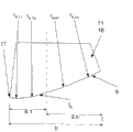
Fig. 1 a has explained the structure by forming unit of the present invention by the sectional view from the axial section of the machine that is used to make web;
Fig. 1 b shows the details by Fig. 1 a;
Fig. 2 a to Fig. 2 c has explained and has been used for influencing the possible embodiment in the dehydration of the second dehydration section;
Fig. 3 a to Fig. 3 c exemplary illustration the possible embodiment of supporting surface; And
Fig. 4 a and Fig. 4 b show the possible structural scheme of each suction district on the dewater unit.
The specific embodiment
Fig. 1 a in the sketch map of extremely simplifying that illustrates by from the cross-sectional illustration of axial section by the basic structure and the basic function of the forming unit 1 of the present invention's structure, this forming unit is used for using at the machine with cause fibrous suspension or nonwoven fabric suspension (next abbreviating fibrous suspension FS as) manufacturing web, especially web of fiber or nonwoven webs.For the direction of in ensuing elaboration, mentioning is described, on this forming unit 1, provide coordinate system.Directions X is illustrated in web that the installation site in the machine that is used for making web the produces direction of passage through this installation site, and also is nominally machine direction MD.The Y direction indication is transverse to the direction of machine direction, and the corresponding width that also is nominally CD or cross-machine direction.Z direction respective heights direction.
Forming unit 1 comprises at least two endless belt sieve bands, and promptly first sieve is with 2 and second to sieve and to be with 3, and this two bar grizzl(e)ies band is arranged in such a way and directs on their subregion of circulation path, makes them form two sieves district 4.Shown under the situation, first sieve with 2 play lower screen cloth in this arrangement effect, second sieve with 3 then formation have the upper screen cloth in the outside 3.1.Forming unit 1 according to Fig. 1 a is implemented as the hybrid shaping device that has long sieve section 5 and two sieves district 4.First sieve is the parts in long sieve section 5 and two sieves district 4 with 2.Fibrous suspension FS this first sieve with on receive and support the ground guiding through mentioned section.In order fibrous suspension FS to be applied to the sieve that preferably is supported on the crooked supporting surface 7 with on 2, especially sieve is with on 2 the outside 2.1, the form of being provided with is the device 6 of flow box.Device 6 comprises the material extrusion device that has at least one material extrusion nozzle, and this material extrusion device extends along the desired width of the width of revolvable supporting surface 7 especially extend past web to be made or along cross-machine direction CD.Device 6 may be embodied to different types.This point is with reference to by the disclosed embodiment of prior art.Crooked supporting surface 7 shown under the situation with can be around axis R
7The mode of rotation is supported and is formed by the curved surface of roller, and the curved surface of roller part at least is with 2 to twine by endless belt sieve.Sieve is turning on the roller and in that segment section ground guiding is through above the dewater unit 8 of form for the sieve table especially at least between supporting surface 7 and the two sieves district 4, the sieve table is arranged in first sieve with 2 inside and on the inboard 2.2 of the first sieve band, support first sieve and be with 2.In the zone of sieve table 8, carry out the dehydration of fibrous suspension FS along gravity direction.About the design reference of sieve table known prior art.It is the ceramic layer of the opening of slit or perforation that sieve table preferably has with form especially, and is the part of long sieve section 5.
In two sieves district 4, fibrous suspension FS is with 2 at two endless belt sieves, guiding between 3,, two bar grizzl(e) y bands 2,3 guided on their subregion of circulation path substantially parallel to each otherly for this reason.The sieve district SZ that meets has described such zone, that is, in this zone, second sieve is cut under the situation of angle beta by first sieve with among the 2 fibrous suspension FS that guided with 3.This zone can be through the beginnings of being supposed in theory and limit and define in addition the effect of two sieves district 4 on fibrous suspension FS along the axis that cross-machine direction CD distributes.
Set inside in two sieves district 4 has at least one, forms the dewater unit 11 of the rigid support face 9 with opening 10.On this dewater unit, second sieve is supported the ground guiding with its inboard of 3 usefulness 3.2.Supporting surface 9 directly is arranged in the back of sieving the district SZ that meets and has described the second dehydration section II.Second sieve appears on the entering line E at supporting surface 9 places with 3.Under the situation that forms the first dehydration section I first sieve with 2 inboard 2.2 on acting dewater unit 12 see the front of the entering line E that is arranged in supporting surface 9 places along the sieve traffic directions; This dewater unit 12 comprises at least one ability flexible support and can support the dewatering elements 13 of first sieve with 2 location; At this is along the dewatering elements 13.1 to 13.n of that arrange each other, form sieve traffic direction each interval and parallel for the lath that can compress; These dewatering elements can deviate from the side that carries fibrous suspension FS one side with they; On inboard 2.2, form acting surface 14.1 to 14.n with sieve with 2 surfaces that contact at this, the size of these acting surfaces can depend on that geometry and/or the physical dimension of lath and layout change.Flexible support is preferably through flexible supporting arrangement, is that the flexible member of spring unit, film or pressure pad is realized through form for example, and therefore allows the motion of acting surface 14.1 to 14.n relative first sieves with 2 inboard 2.2.In addition, acting surface 14.1 separately is to 14.n, and lath especially separately can for example be with 2 to push by corresponding regulator to first sieve by the preferred power that can freely select.
In advantageous embodiment, a plurality of dewatering elements 13.1 is set in the first dehydration section I to 13.n.Quantity is between 1 and 5, preferably between 1 to 3, be preferably 3 especially.Be arranged in get into before the line E and preferably extend to this enterings line first dewater section I length l
I, observe at first sieve, for 20mm to 600mm, preferred 60mm to 450mm, be preferably 330mm especially with 2 sieve traffic direction.Two arranged adjacent, can support first sieve with the spacing a13 between the dewatering elements 13.1 to 13.n of 2 location preferably between the 40mm to 240mm, be preferably 120mm.Will the last dewatering elements 13.n before sieve be positioned at the entering line E at supporting surface 9 places on the traffic direction this with get into line E and be separated by and arrange in the mode of the spacing a of 20mm to 200mm scope.The angle of attack alpha (Anstellwinkel) of each dewatering elements 13.1 to 13.n is preferably between-2 ° to+2 °.At this, the sieve district SZ that meets is implemented in the zone of extension of the first dehydration section I, preferably on dewatering elements 13.n.Each spacing a13, angle of attack alpha and each acting surface 14.1 between two dewatering elements disposed adjacent one another 13.1 to 13.n to 14.n's and/or the physical dimension/embodiment of whole dewatering elements 13.1 to 13.n may be embodied to identical, approximately uniform or differ from one another.
At least one, preferably all single dewatering elements 13.1 to 13.n are used for bringing pressure pulse into sieve and are with 2, and this sieve is with and again these pressure pulses is passed to fibrous suspension FS, and said dewatering elements can be constructed for this reason with compressing.Flexible support and compress and the generation of thrust can for example mechanically, hydraulically or pneumatically realize.In particularly advantageous embodiment, flexible support is born by components identical when function is concentrated with the function that compresses.At this, have the embodiment of the cases of dehydration of only passive influence in the first dehydration section I and have between the embodiment that initiatively influences different.Under first situation about mentioning, with the adaptation of the situation of forming unit 1 adjustment in service in, each dewatering elements is supported flexibly and acting surface is being supported sieve with given in advance power all the time be with 2 location.Initiatively influence then mean each acting surface 14.1 to 14.n to sieve with 2 thrust variable adjustable in time and/or on the place.Each dewatering elements 13.1 to 13.n does not have mechanical attachment for this reason to each other, but can be bearing on the common bogey.At this, each dewatering elements 13.1 to 13.n can or individually, controlled group by group or jointly, for this reason, can be they attach troops to a unit each one own regulators or be a plurality of dewatering elements regulators of jointly attaching troops to a unit.
The first and second dehydration section I, II are along sieving directly front and back arranged in succession of traffic direction; Wherein according to the present invention; After the dehydrations that in the first dehydration section I, freely adjust by dewatering elements 13.1 to the 13.n preferred abilities ability flexible support and the ability flexible positioning; Two endless belt sieves with 2 and 3 with the fibrous suspension FS that is between them; Entering line E from the supporting surface 9 at least one crooked subregion 9.1 of implementing, that is to say on the initiation region of supporting surface 9 and guides; Be used to realize the influence of the ACTIVE CONTROL sensitively of dewatering or passive influence, and in the high sieve speed of service the desired best dewatering pressure curve of adjustment.Supporting surface 9 this initial bending in subregion 9.1 can be passed through radius r at this
9.1Or the sequence description of a plurality of radiuses, and the structure of relevant dewater unit 11 protrudes.In advantageous embodiment, supporting surface 9 is configured to crooked from the zone of withdrawing from line A of supporting surface 9 at second sieve equally with 3.In particularly advantageous embodiment, the guiding of in the second dehydration section II, on the supporting surface 9 of complete curved configuration, sieving.At this, the envelope of describing supporting surface 9 characterizes through one or more radiuses.Each radius is between 1m and 10m, preferably selecting between the 2m to 5m.These radiuses can adapt with instructions for use aspect size and the sequence changeably.Through the guiding of the sieve on curved surface, each is endless belt with 2 with 3 with the fibrous suspension FS or the web of formation that are between these bands, also stable through fully under very high speed conditions.Especially can acquire a great preponderance at a high speed and under the situation of the high water yield.
In particularly advantageous embodiment, supporting surface 9 be arranged on the upper screen cloth suction box 18 and for example by the planar elements of a band opening 10 or a plurality of on the sieve traffic direction each interval slab element 19.1 to 19.n that is with forming acting surface 21.1 to 21.n that arrange, rigidity form.First slab element that is that on the sieve traffic direction, is arranged on the supporting surface 9 works with Reference numeral 17 marks and as being used to peel off through the skimming lath of second sieve with the fluid of 3 outflows.The enforcement that is slab element 19.1 to 19.n of rigidity and/or physical dimension and arrange can identical ground, approximate identical ground or dissimilar the realization.
Importantly, in this area E that is getting into, that is to say, only realize one, sieve with the 3 especially preliminary dehydrations of passing through dewater unit 11 of top sieve band direction towards second getting into line E rear in two sieve bands layout II.At this, when dewater unit 11 is implemented as upper screen cloth suction box 18, begin in supporting surface 9, especially skimming lath 17 sieve are before met the district with 3 preliminary hydro-extractions through second sieve.Will be from seldom fluid, the especially plain boiled water on concentrated surface of fibrous suspension FS; At this based on can flexible support and can support first sieve and be with 3 to push through second sieve with the effect of the dewatering elements 13.1 to 13.n of 2 location; Peel off by skimming lath 17 through its water of deviating from, and upwards preferred through discharging in this unshowned region of no pressure.The upper screen cloth suction box characterizes through at least one suction district or a plurality of suction district at this.The preliminary hydro-extraction of this gentleness has huge advantage in the boots or the dehydration on the forming rolls of bending relatively.Can describe through it and to be used to support the length l of second sieve with 3 envelope
IIPreferably between 50mm to 1000mm, preferably between 60mm to 300mm but be at least 50mm ground and select.
On the second dehydration section II; Can be with 3 further from supporting surface 9 comes out after at second sieve; Will be at this unshowned dehydration section; Especially the sieve that is connected in the formed article shaped of further transportation is with on 2 or 3, be with on 2 for the sieve after in separated region 20, separating with 2,3 at sieve at this, and said separation is supported through resolution element, the roller 23 that especially can aspirate or crooked aspirator.They can be the parts of other functional unit outside the dewater unit 11.
With particularly advantageous mode; Supporting surface 9 can be in subregion 9.1 the embodiment of initial bending at least after through describing with other straight or curved surf zone that withdraws from line A of 3 until second sieve; For example regional here 9.n and two sieves district 4 that also can on dehydration section II, extend out can characterize through other unshowned dewater units, and these other unshowned dewater unit is arranged in the first dehydration section and the second dehydration section II back along the sieve traffic direction.There is not restriction aspect each the structure of dewater unit.These dewater units can be to be arranged in dewatering elements in the sieve band of further guiding article shaped, that have smooth or crooked supporting surface according to the difference of embodiment, and they are maybe adjusting of maintenance.
Utilize the described combination of known measure separately; Can upwards realize two-stage or multistage preliminary hydro-extraction, especially through the guiding on dewatering elements 13.1 to 13.n on a series of inboards 2.2 that are installed in the outside 2.1 that deviates from bearing fiber suspension FS neatly and the supporting surface 9 at least initially, preferably implemented fully agley subsequently.Fig. 1 a has only explained basic layout at this, and this arranges that basically the combinations through the two sieves district 4 that dewatering elements 13.1 to 13.n and ensuing subregion 9.1 with bending of dewater unit 11 flexibly directly is connected to the structural scheme that gets on the line E characterize.
Fig. 1 b shows two dehydration section I, II and each parameter, especially angle of attack alpha and entrance angle beta once more with the amplification detailed view by Fig. 1 a.This basic layout can be made amendment for the advantage that obtains other.This type modification is as further providing in Fig. 2 a to 2c.
Fig. 2 a by the cross-sectional illustration of the view of pressing two of Fig. 1 a dehydration section I, II first improvement project; In this improvement project; Inner at the second dehydration section II along sieving traffic direction from getting into line E; Relatively get into that line is arranged with spacing b, in the inner subregion 9.x of the regional 9.n of supporting surface 9, be provided with supporting surface opposed to each other at first sieve on 2, especially away from the dewatering elements that directly comes into force 15.1 on the side 2.2 of supporting surface 9 to 15.n.These dewatering elements preferably neatly endless belt sieve with 2 inboard 2.2 on, relatively second sieve with 3 on, the opening of the dewater unit 11 that especially comes into force on inboard 3.2 is 10 that arranged, can flexible support and can support the lath of first sieve with 2 location.If being with at second sieve, enforcement dewater unit 11 has supporting surface 9 in 3; This supporting surface is by forming along the spaced apart slab element 19.1 to 19.n that is of sieve traffic direction; Dewatering elements 15.1 to 15.n and these are the slab element and stagger so, that is to say to be arranged in first sieve with on the breach in 2.Subregion 9.x can directly be connected on the subregion 9.1 of the initial bending of describing supporting surface 9 or is arranged in this subregion arbitrarily and withdraws between the line A at this.Supporting surface 9 is structure and through radius r or preferred a series of radius r fully agley preferably
9.11To r
9.nn(n>=1) characterizes.Importantly; Through dewater unit 11 towards second sieve with 3, especially after the preliminary hydro-extraction of top sieve band, promote through other dewatering elements 15.1 to 15.n in first sieves with 2 in the dehydration that is connected in the zone after this preliminary hydro-extraction of dehydration section II.Along the bearing of trend of the upper screen cloth suction box 18 and then the second dehydration section II, for example have to be arranged in first sieve with the inner shaping box of 2 loop for this reason.It is that the dewatering elements 15.1 of shaping lath is to 15.n that this shaping box is equipped with each form.These dewatering elements are positioned between the element that is slab 19.1 to 19.n of upper screen cloth suction box 18 and press to two endless belt sieves through corresponding devices, especially regulator at this is with 2,3.The thrust of each dewatering elements 15.1 to 15.n can freely be adjusted with particularly advantageous mode; That is to say; Each or a plurality of this dewatering elements connect with the device that is used to load thrust accordingly, thereby can adjust the thrust of the endless relatively belt sieve of each dewatering elements 15.1 to 15.n with 2 inboard 2.2 changeably.This is adjusted at, and this is single or carry out group by group on each dewatering elements 15.1 to 15.n.
Fig. 2 b has explained the improvement project by the embodiment of Fig. 1 a; But in this improvement project; Substitute the embodiment of pressing Fig. 2 a; In the subregion 9.1 that the initial bending of supporting surface 9 is implemented, be furnished with can flexible support and can support first sieve with the dewatering elements 16.1 of 2 location to 16.n, in the regional 9.n that is connected in subregion 9.1 back, then do not establish this class component.
In contrast, Fig. 2 c has explained the combination by the embodiment of Fig. 2 a and Fig. 2 b, wherein, in two zones 9.1 and 9.x, be provided with can flexible support and can support first sieve with the dewatering elements 15.1 to 15.n and 16.1 of 2 location to 16.n.
Fig. 3 a to Fig. 3 c is to have explained the possible embodiment of supporting surface 9 through the reduced graph that illustrates.These embodiments are not final.
At this, according to Fig. 3 a, design is on dewater unit 11 like this for supporting surface 9, and the subregion 9.1 of initial bending passes through radius r
9.1Characterize, this subregion extends at supporting surface 9 along the sieve traffic direction from getting into line E.Remaining subregion 9.n can pass through radius r
9.nDescribe.
In contrast, Fig. 3 b has explained the possibility of the embodiment at least one subregion 9.1 and 9.n of supporting surface 9, and at this, subregion 9.1 for example is radius r through a plurality of radiuses at this
9.11To r
9.1nCharacterize.At this, radius r
9.11To r
9.1nDiffer from one another to rising or decline.In contrast, Fig. 3 c has exemplarily explained the embodiment by Fig. 3 b, and this embodiment also is designed with is with a plurality of different radii r
9.n1To r
9.nnSubregion 9.n.
Fig. 4 a use through simplifying greatly of illustrating, be used for being used to produce the attachment relationship of means for applying negative 22 and at each subregion 9.1 and the suction district S9.1 of 9.n and the structure of S9.n of supporting surface 9 by having illustrated of the embodiment of the dewater unit 11 of Fig. 3 a.In contrast; Fig. 4 b shows improvement project; In this improvement project, negative pressure along direction of passage in succession subregion 9.1 and the 9.n before and after the sieve traffic direction of supporting surface 9, can and control suction district S9.11 to S9.1n at least through structure, S9.n1 to S9.nn distinguish individually or divide into groups jointly to adjust.
To in the embodiment shown in Fig. 1 a to Fig. 4 b, about the concrete parameter declaration of the enforcement, physical dimension and the layout that are used for the dewatering elements and the second dehydration section II, can be with reference to the embodiment in Introductory part.The member that forms the first and second dehydration sections is arranged in such a way and implements, that is, the dehydration ratio in these dehydration sections of making is in 0.3 to 4 the scope each other.
Be not limited in the embodiment shown in Fig. 1 a to Fig. 4 b by technical scheme of the present invention.
Reference numerals list
1 forming unit
2 first sieve bands
2.1 the outside
2.2 it is inboard
3 second sieve bands
3.1 the outside
3.2 it is inboard
4 sieve districts
5 long sieve sections
6 to be used to apply fibrous suspension or nonwoven fabric outstanding
The device of supernatant liquid, especially flow box
7 supporting surfaces
8 dewater units
9 supporting surfaces
9.1 subregion has the initial bending of supporting surface
9.x, the subregion of 9.n supporting surface
10 openings
11 dewater units
12 dewater units
13.1-13.n dewatering elements
14.1-14.n acting surface
15.1-15.n dewatering elements
16.1-16.n dewatering elements
17 skimming laths
18 upper screen cloth suction box
19.1 be the slab element to 19.n
20 Disengagement zone
21.1-21.n acting surface
22 are used to produce means for applying negative
23 rollers that can aspirate
A is between last dewatering elements and entering line
Spacing
A13 is arranged adjacent on two edge sieve traffic directions
Dewatering elements between spacing
The alpha angle of attack
B subregion 9.2 and the spacing that gets into line E
The beta entrance angle
The CD cross-machine direction
E gets into line
The FS fibrous suspension
The I first dehydration section
The II second dehydration section
l
IThe length of the first dehydration section
l
IIThe length of the second dehydration section
The MD machine direction
R
7The rotation of supporting surface 7
r
9.1, r
9.nRadius
r
9.11-r
9.1n, r
9.n1-r
9.nnRadius
S9.1-S9.n, S9.11-S9.nn suction district
SZ sieves the district of meeting
X, Y, Z coordinate
Claims (33)
1. forming unit (1), especially page or leaf are opened and are formed the unit, are used for using at the machine of making web with cause fibrous suspension or nonwoven fabric suspension (FS), comprising:
Article at least two, endless belt sieve band (2,3), said sieve band are guided with the mode that constructs two sieve districts (4) at least one subregion of their circulation path,
Dewater unit (11), said dewater unit in the second sieve band (3) of said two sieves district (4) internal placement in this two bar grizzl(e)ies band and for this second sieve band (3) is formed on supporting surface (9) rigidity and that have the opening (10) that can aspirate in the operating position, and
That at least one entering line (E) that extends along cross-machine direction (CD) of locating at said supporting surface (9) at the said second sieve band (3) is arranged before, with the mode that constructs the first dehydration section (I) at the last acting dewater unit (12) of the first sieve band (2); This dewater unit (12) comprises at least one ability flexible support and can support the dewatering elements (13.1-13.n) of said first sieve band (2) location
It is characterized in that,
At least one of the said supporting surface (9) of the description second dehydration section (II) directly is arranged in the subregion (9.1) at said entering line (E) rear and constructs agley on the sieve traffic direction.
2. by the described forming unit of claim 1 (1); It is characterized in that; The guide element of said two bar grizzl(e)y bands (2,3) constructs as follows and arranges, that is, sieve meet district (SZ) be arranged in said entering line (E) before with said first section (I) inside of dewatering; In the said sieve district (SZ) of meeting, the said second sieve band (3) is cut at the said first sieve band (2) and goes up in the said fibrous suspension (FS) of guiding with preferred entrance angle (beta) that can adjustment.
3. by claim 1 or 2 described forming units (1); It is characterized in that; Week at the said first sieve band (2) upwards observes, and the said first dehydration section (I) that the said entering line of locating at said supporting surface (9) at the said second sieve band (3) (E) is arranged before has 20mm to 600mm, preferred 60mm to 450mm, the especially preferred length of 330mm.
4. by one of aforementioned claim described forming unit (1); It is characterized in that; In said first dehydration section (I) the said first sieve band (2) go up acting dewater unit (12) comprise a plurality of that each interval is arranged on the sieve traffic direction, can flexible support and can support the dewatering elements (13.1-13.n) of said first sieve band (2) location; Especially the lath that also is formed for being with the acting surface (14.1-14.n) of (2) mating reaction respectively that extends transverse to said sieve traffic direction with said first sieve; Wherein, the quantity of these dewatering elements (13.1-13.n) preferably in 1 to 5 scope, particularly preferably in 1 to 3 the scope, be preferably 3 especially.
5. by the described forming unit of claim 4 (1), it is characterized in that, two along in the scope of spacing (a13) between dewatering elements sieve traffic direction arranged adjacent, that can support said first sieve band (2) location at 40mm to 240mm, be preferably 120mm.
6. by one of aforementioned claim described forming unit (1); It is characterized in that, along the sieve traffic direction the said second sieve band (3) said entering line (E) that said supporting surface (9) is located before last ability the flexible support in the said first dehydration section (I) and the dewatering elements (13.n) that can support said first sieve band (2) location with apart from said entering line (E) 20mm to 200mm, preferably 60mm to 120mm, the spacing (a) that is preferably 90mm are especially arranged.
7. by one of aforementioned claim described forming unit (1); It is characterized in that; Each, be arranged in said first dehydration section (I), can flexible support and the dewatering elements (13.1-13.n) that can support said first sieve band (2) location implement as follows; That is, said dewatering elements can compress to the said first sieve band (2) with pressure in 0mbar to the 400mbar scope, in preferred 60mbar to the 250mbar scope.
8. by one of aforementioned claim described forming unit (1); It is characterized in that, each, can flexible support and can support said first sieve band (2) location dewatering elements (13.1-13.n) layout and/or implement through at least one sign in the property:
The angle of attack (alpha) of-said relatively first sieve band (2)-2 ° with+2 ° scope in;
The geometry of-acting surface (14.1-14.n) and physical dimension, especially in action length the scope at 5mm to 30mm of sieve on the traffic direction, and/or the radius on the leading edge is in 0mm and 5mm scope.
9. by one of aforementioned claim described forming unit (1), it is characterized in that the said first dehydration section (I) extends the said entering line of locating at said supporting surface (9) until the said second sieve band (3) (E).
10. by one of aforementioned claim described forming unit (1); It is characterized in that; Regional structure along the ground of the initial bending at least structure that the sieve traffic direction extends becomes protruding to said supporting surface (9) from said entering line (E), and the said second dehydration section (II), can be through in the scope of length (lII) of describing at the envelope that sieves the said supporting surface of sign (9) on the traffic direction, preferably in the scope at 60mm to 300mm but be at least 50mm at 50mm to 1000mm.
11., it is characterized in that said supporting surface (9) is preferably constructed in the scope that withdraws from line (A) of said supporting surface (9) at the said second sieve band (3) in addition at least fully agley by the described forming unit of claim 10 (1).
12., it is characterized in that each the envelope of bending of describing said supporting surface (9) is through at least two radius (r of a sequence by one of aforementioned claim described forming unit (1)
9.1-r
9.nr
9.11-r
9.1nr
9.n1-r
9.nn) characterize.
13. by the described forming unit of claim 12 (1), it is characterized in that, at said second sieve band (3) radius (r in the zone of the said entering line (E) that said supporting surface (9) is located
9.1) in the scope between 0.1m and infinity, preferably in the scope between the 0.1m to 5m.
14., it is characterized in that each said radius (r by claim 12 or 13 described forming units (1)
9.1-r
9.nr
9.11-r
9.1nr
9.n1-r
9.nn) in the scope between 1m and 10m, preferably in the scope of 2m to 5m.
15. by one of aforementioned claim described forming unit (1); It is characterized in that the surface said supporting surface (9) of the said second dehydration section (II) of the description of said dewater unit (11), that can describe through said opening (10), that open wide is 20% to 90%, preferably 40% to 90% of a said supporting surface (9).
16., it is characterized in that the ratio of the said supporting surface (9) of the said second dehydration section (II) and the length of the said first dehydration section (I) is in 10 to 0.1 scope, in preferred 5 to 0.2 the scope by one of aforementioned claim described forming unit (1).
17. by one of aforementioned claim described forming unit (1); It is characterized in that; Be arranged in said entering line (E) that said supporting surface (9) locates afterwards along the sieve traffic direction, in the said second dehydration section (II) for the said first sieve band (2) attach troops to a unit at least one, preferred a plurality of can flexible support and can support the said first sieve band (2) at said supporting surface (9) along other the dewatering elements (15.1-15.n, 16.1 is to 16.n) of locating in the zone that the sieve traffic direction extends.
18. by the described forming unit of claim 17 (1); It is characterized in that; Along the sieve traffic direction be arranged in said entering line (E) that said supporting surface (9) locates afterwards, in the said second dehydration section (II), attach troops to a unit in the said first sieve band (2), can flexible support and can support the said first sieve band (2) said supporting surface (9) be arranged in along said other the dewatering elements (16.1-16.n) of locating in the zone that the sieve traffic direction extends from said entering line (E) through at least a portion of the subregion (9.1) of the initial bending enforcement of said supporting surface (9) first, or fully on said subregion.
19. by claim 17 or 18 described forming units (1); It is characterized in that, along the sieve traffic direction be arranged in said entering line (E) that said supporting surface (9) locates afterwards, in the said second dehydration section (II), attach troops to a unit in the said first sieve band (2), can flexible support and can support the said first sieve band (2) and be arranged at least one subregion (9.x) of arranging with spacing (b) apart from said entering line (E) of said supporting surface (9) along said other the dewatering elements (15.1-15.n) of locating in the zone that the sieve traffic direction extends at said supporting surface (9).
20. by one of aforementioned claim described forming unit (1); It is characterized in that, each in said first dehydration section (I) and/or said second dehydration section (II), can flexible support and the dewatering elements (13.1-13.n, 15.1-15.n, 16.1-16.n) that can support said first sieve band (2) location by can compress changeably, form transverse to the slab element that is of sieve traffic direction extension.
21. by the described forming unit of claim 20 (1); It is characterized in that; In said first dehydration section (I) and/or said second dehydration section (II) each, can flexible support and the dewatering elements (13.1-13.n, 15.1-15.n, 16.1-16.n) that can support said first sieve band (2) location with regard to they flexible support and/or supporting said first sieve and be with regard to the location of (2); Respectively at dehydration section (I; II) inner identical ground, approximate identical ground or different enforcement, and can be individually, control group by group or jointly.
22. by one of aforementioned claim described forming unit (1), it is characterized in that, the said supporting surface (9) of describing the said second dehydration section (II) by a plurality of sieve traffic directions along band at each interval, the lath (19.1-19.n) arranged abreast forms.
23., it is characterized in that the said supporting surface (9) of describing the said second dehydration section (II) is formed by the surface of punching by one of claim 1 to 21 described forming unit (1).
24., it is characterized in that attaching troops to a unit for said supporting surface (9) has at least one to be used to produce means for applying negative (22) by one of aforementioned claim described forming unit (1).
25., it is characterized in that said negative pressure is to adjust along the sieve traffic direction and/or transverse to the sieve traffic direction by the described forming unit of claim 24 (1).
26. by one of aforementioned claim described forming unit (1); It is characterized in that; Endless belt first band (2) is implemented as the top sieve band, and the said dewater unit (11) that forms said supporting surface (9) is implemented as upper screen cloth suction box (18) and said entering line (E) is formed in the zone of skimming lath (17).
27. by one of aforementioned claim described forming unit (1); It is characterized in that; Said forming unit is configured to the mixed-forming device; And the said first sieve band (2) is the part of long sieve section (5), at first sieve band guiding process at least one dewater unit (8), especially the sieve table described in the said length sieve section.
28. by one of aforementioned claim described forming unit (1); It is characterized in that; The member that forms said first dehydration section (I) and the said second dehydration section (II) is arranged in such a way and implements; That is, in these dehydrations sections (I, II) each other dehydration ratio in 0.3 to 4 scope.
29. be used in the forming unit (1) of the machine of making web with cause fibrous suspension or nonwoven fabric suspension (FS), making the method for web; In said method, will be applied to the said fibrous suspension (FS) on the first sieve band (2) by the device that is used to apply (6)
Flow to two sieve districts (4),
In the zone (SZ) that the said first sieve band (2) and the sieve of other the second sieve band (3) are met, in the first dehydration section (I), dewater through in the material width of cloth, introducing at least one dehydration pulse that is arranged in the said first sieve band (2), and
Upward dewater going up supporting surface (9) acting and that support said second sieve rigidity band, that have the opening that can aspirate at the said second sieve band (3) in the second dehydration sections (II) subsequently in said two sieve districts (4),
It is characterized in that,
The guiding of said sieve band (2,3) in the said second dehydration section (II) carried out on initial bending ground at least.
30. by the described method of claim 29; It is characterized in that the dehydration pulse that can in the said first dehydration section (I), introduce in the said first sieve band (2) can be adjusted at the extension upper edge of the said first dehydration section (I) sieve traffic direction and/or transverse to the sieve traffic direction changeably.
31., it is characterized in that the stress that the dehydration in the said second dehydration section (II) is based on the said sieve band (2,3) of the last guiding of said supporting surface (9) carries out by claim 29 or 30 described methods.
32. by one of claim 29 to 31 described method; It is characterized in that, can through use at least one, preferred a plurality of other ability flexible support and can support said first dewatering elements (15.1-15.n, 16.1-16.n) sieve band (2) location and that arrange on said supporting surface (9) opposite and influencing said second dehydration of dewatering in the section (II).
33. by one of claim 29 to 32 described method; It is characterized in that; Ability flexible support in said first dehydration section (I) and/or said second dehydration section (II) and the dewatering elements (13.1-13.n, 15.1-15.n, 16.1-16.n) that can support said first sieve band (2) location are with regard to their effect, along sieve traffic direction and/or single or control changeably group by group transverse to sieve traffic direction ability.
Applications Claiming Priority (3)
| Application Number | Priority Date | Filing Date | Title |
|---|---|---|---|
| DE200910027432 DE102009027432A1 (en) | 2009-07-02 | 2009-07-02 | Forming unit and method for producing a material web |
| DE102009027432.4 | 2009-07-02 | ||
| PCT/EP2010/056054 WO2011000614A1 (en) | 2009-07-02 | 2010-05-05 | Forming unit and method for producing a material web |
Publications (2)
| Publication Number | Publication Date |
|---|---|
| CN102472010A true CN102472010A (en) | 2012-05-23 |
| CN102472010B CN102472010B (en) | 2015-01-28 |
Family
ID=42830239
Family Applications (1)
| Application Number | Title | Priority Date | Filing Date |
|---|---|---|---|
| CN201080029888.1A Active CN102472010B (en) | 2009-07-02 | 2010-05-05 | Forming unit and method for producing a material web |
Country Status (4)
| Country | Link |
|---|---|
| EP (1) | EP2449174B1 (en) |
| CN (1) | CN102472010B (en) |
| DE (1) | DE102009027432A1 (en) |
| WO (1) | WO2011000614A1 (en) |
Families Citing this family (3)
| Publication number | Priority date | Publication date | Assignee | Title |
|---|---|---|---|---|
| DE102010030707A1 (en) | 2010-06-30 | 2012-01-05 | Voith Patent Gmbh | Sheet forming system for a machine for producing an at least single-layer fibrous web |
| DE102011080424A1 (en) * | 2011-08-04 | 2013-02-07 | Voith Patent Gmbh | Sheet forming system for a machine for producing a two- or multi-layer fibrous web |
| CN203475224U (en) * | 2012-06-19 | 2014-03-12 | 沃依特专利有限责任公司 | Pressing device of machine used for manufacturing fiber material web |
Citations (4)
| Publication number | Priority date | Publication date | Assignee | Title |
|---|---|---|---|---|
| CN1049037A (en) * | 1989-05-08 | 1991-02-06 | 维美德-阿尔斯特罗姆有限公司 | The forming method of paper web and equipment |
| DE4219292A1 (en) * | 1992-06-12 | 1993-12-16 | Escher Wyss Gmbh | Twin wire former |
| US5320713A (en) * | 1990-01-26 | 1994-06-14 | Sulzer Escher Wyss Gmbh | Method of using a forming section of a papermaking machine |
| US20080135197A1 (en) * | 2005-08-12 | 2008-06-12 | Johann Moser | Method for producing a firous web and twin mesh former for performing said method |
Family Cites Families (7)
| Publication number | Priority date | Publication date | Assignee | Title |
|---|---|---|---|---|
| US3803604A (en) | 1972-07-07 | 1974-04-09 | Rca Corp | Digital tracker |
| GB8307435D0 (en) | 1983-03-17 | 1983-04-27 | Beloit Walmsley Ltd | Dewatering apparatus |
| DE4005420C2 (en) | 1990-02-21 | 1995-06-08 | Voith Gmbh J M | Twin wire former |
| DE4326867C2 (en) | 1993-08-11 | 1997-01-30 | Voith Gmbh J M | Screen section of a machine for the production of fibrous webs |
| CA2489659C (en) | 2002-08-23 | 2010-02-16 | Metso Paper, Inc. | Forming of a paper or board web in a twin-wire former or in a twin-wire section of a former |
| DE102005047347A1 (en) | 2005-09-30 | 2007-04-12 | Voith Patent Gmbh | Method for producing a fibrous web and sheet forming system for carrying out the method |
| DE102007000065A1 (en) | 2007-02-01 | 2008-08-07 | Voith Patent Gmbh | Process for producing a fibrous web and twin-wire former for carrying out the process |
-
2009
- 2009-07-02 DE DE200910027432 patent/DE102009027432A1/en not_active Withdrawn
-
2010
- 2010-05-05 CN CN201080029888.1A patent/CN102472010B/en active Active
- 2010-05-05 WO PCT/EP2010/056054 patent/WO2011000614A1/en active Application Filing
- 2010-05-05 EP EP10720288.9A patent/EP2449174B1/en active Active
Patent Citations (4)
| Publication number | Priority date | Publication date | Assignee | Title |
|---|---|---|---|---|
| CN1049037A (en) * | 1989-05-08 | 1991-02-06 | 维美德-阿尔斯特罗姆有限公司 | The forming method of paper web and equipment |
| US5320713A (en) * | 1990-01-26 | 1994-06-14 | Sulzer Escher Wyss Gmbh | Method of using a forming section of a papermaking machine |
| DE4219292A1 (en) * | 1992-06-12 | 1993-12-16 | Escher Wyss Gmbh | Twin wire former |
| US20080135197A1 (en) * | 2005-08-12 | 2008-06-12 | Johann Moser | Method for producing a firous web and twin mesh former for performing said method |
Also Published As
| Publication number | Publication date |
|---|---|
| EP2449174B1 (en) | 2013-08-07 |
| CN102472010B (en) | 2015-01-28 |
| DE102009027432A1 (en) | 2011-01-05 |
| WO2011000614A1 (en) | 2011-01-06 |
| EP2449174A1 (en) | 2012-05-09 |
Similar Documents
| Publication | Publication Date | Title |
|---|---|---|
| EP0571585B1 (en) | Twin-wire former | |
| FI70739C (en) | BANBILDNINGSENHET VID FRAMSTAELLNING AV FLERSKIKTSKARTONG | |
| US2881676A (en) | Paper or board machine and method | |
| CA1045432A (en) | Stock formation in a paper making process | |
| EP2576895B1 (en) | Machine, method and use of the machine for producing a paper web, in particular a sack paper web | |
| EP0933473A2 (en) | Twin-wire former | |
| FI93032C (en) | Two-wire web forming section of a paper machine | |
| DE3410171A1 (en) | PAPER MACHINE PRESS PART WITH CLOSED GUIDE | |
| CN102472010A (en) | Forming unit and method for producing a material web | |
| JPH01501074A (en) | Machine for forming textile material webs | |
| CN101057029B (en) | Method and apparatus of a twin-wire press | |
| US2881675A (en) | Method and apparatus for de-watering aqueous pulp or stock in the manufacture or paper or board | |
| FI105491B (en) | Multi-ply paper forming system | |
| DE19733316A1 (en) | Method and device for forming a fibrous web | |
| EP1936026B1 (en) | Wet end for a machine producing lengths of fibrous material, in particular paper machines for creating wood-free paper | |
| DE2027326A1 (en) | Papermaking equipment | |
| AT506985A2 (en) | PRESS, FORMING PART AND APPENDIX FOR PRODUCING A MULTILAYER MATERIAL RAIL | |
| DE10116867A1 (en) | Paper making sieve conveyer has curved water suction head positioned at junction of two dewatering planes | |
| WO2013041341A1 (en) | Sheet forming device for a machine for producing a fibrous material web from at least two fibrous material suspensions | |
| FI115849B (en) | Arrangement of wire section of paper or board machine | |
| EP3447175A1 (en) | Nonwoven fabric layer and nonwoven fabric laying method | |
| WO2018206216A1 (en) | Device and method for producing a fibrous web | |
| WO1995019467A1 (en) | Process and twin-wire former to form a fibre material web | |
| WO2013026597A1 (en) | Twin-wire former for a machine for producing a fibrous web from at least one fibrous-material suspension | |
| DE19949354A1 (en) | Assembly for the prodn of a multi-layer paper/cardboard web has a number of web formation zones with their stock inlets for secondary layers to be laid on the primary layer with bonding between them |
Legal Events
| Date | Code | Title | Description |
|---|---|---|---|
| C06 | Publication | ||
| PB01 | Publication | ||
| C10 | Entry into substantive examination | ||
| SE01 | Entry into force of request for substantive examination | ||
| C14 | Grant of patent or utility model | ||
| GR01 | Patent grant |