CN102288252A - System for testing micro leakage of sealed component - Google Patents
System for testing micro leakage of sealed component Download PDFInfo
- Publication number
- CN102288252A CN102288252A CN 201110121689 CN201110121689A CN102288252A CN 102288252 A CN102288252 A CN 102288252A CN 201110121689 CN201110121689 CN 201110121689 CN 201110121689 A CN201110121689 A CN 201110121689A CN 102288252 A CN102288252 A CN 102288252A
- Authority
- CN
- China
- Prior art keywords
- pressure
- test
- environment
- valve
- tested
- Prior art date
- Legal status (The legal status is an assumption and is not a legal conclusion. Google has not performed a legal analysis and makes no representation as to the accuracy of the status listed.)
- Granted
Links
Images


Landscapes
- Examining Or Testing Airtightness (AREA)
Abstract
The invention discloses a system for testing micro leakage of a sealed component. The system comprises a pressure supply system, a pressurizing system, a pressure adjusting system, a pressure maintaining test system, a pressure release safety system and an integral control system, wherein the pressure supply system is used for supplying high pressure hydraulic motive power higher than the test requirement to a component to be tested; the pressurizing system is used for supplying an analogue working environment to the component to be tested; the pressure adjusting system is used for precisely adjusting a pressure difference environment required by the component to be tested so as to further approach to a working pressure environment of the component to be tested; and the pressure maintaining test system is used for calculating the leakage of liquid under a pressure maintaining environment by checking up the pressure change of the liquid under the pressure maintaining environment. According to the testing system disclosed by the invention, the problem of low testing precision of the traditional leakage testing system is solved; the rapid and precise measurement is realized; simultaneously, the universal measurement to gas and liquid sealed components is satisfied; and the leakage of a unit time component can be calculated precisely.
Description
Technical field
The present invention relates to a kind of test macro of seal element tiny leakage amount.
Background technology
In various industrial systems and auto industry, high pressure and vacuum work link are comparatively common.All exist certain leakage rate allowable for common fuel injector of a lot of components and parts especially valve class components and parts such as motor car engine etc., the leakage rate of these elements and leakage rate allowable all are extremely micro-under many circumstances, are difficult to detection or detect cost higher relatively by classic method.
Present existing checkout equipment is existing more, leak as ultrasound examination, this method for the Leak Detection of gas comparatively effectively but also unusual height of the lower limit of its detection, it detects mechanical wave vibration that principle is the characteristic frequency sent when leaking of probe gas, this method for and the seepage of trace be helpless.Also have to be exactly to detect at the concentration of particular chemical character gas.The limitation of this method is to detect the concentration of specific gas, but can not accurately estimate leakage rate, because the gas that leaks out is difficult to be controlled in certain volume.In addition, for the overwhelming majority do not fire, the nontoxic and insensitive gas of chemical reaction or the present prior art of liquid also can't detect.
Summary of the invention
At the deficiencies in the prior art, the object of the present invention is to provide a kind of test macro of seal element tiny leakage amount, this test macro has not only solved the not high problem of traditional leakage rate test system and test precision, realize quick, precision measurement, satisfy simultaneously the universalization of gas, hydraulic seal element is measured, and leakage rate that can accurate Calculation unit interval components and parts.
For achieving the above object, the invention provides a kind of test macro of seal element tiny leakage amount, comprise the pressure feed system, compression system, voltage-regulating system, the pressurize test macro, pressure release security system and complete machine control system, wherein said pressure feed system provides the highly pressurised liquid that is higher than test request power for tested element, described compression system provides the working environment of a simulation for tested element, described voltage-regulating system can accurately be adjusted tested element required pressure difference ring border, further approach the working pressure environment of tested element, described pressurize test macro can be calculated the leakage rate of liquid under the pressurize environment by the pressure change of checking test liquid under the pressurize environment, described compression system comprises a surplus valve, two pressure transducers, a solenoid directional control valve, a retaining valve, a reservoir, pressure control switch and plurality of pipelines, described voltage-regulating system comprises two surplus valves, two solenoid directional control valves, a retaining valve, a hydraulic control one-way valve, a pressure transducer, a reservoir, described pressurize test macro comprises a pressure transducer, a reservoir, a retaining valve, a hydraulic control one-way valve, an observable tensimeter and tested element, described pressure release security system comprises a hydraulic control one-way valve, a solenoid directional control valve, a surplus valve, described complete machine control system comprises master controller, communication bus and interface circuit, and being distributed in each subsystem parts interior various sensors and electronic control unit, the various sensors of each subsystem inside are connected with master controller by interface circuit with electronic control unit.
Detection method of the present invention is as follows:
The first step is installed in tested element on the measuring head, and is fixing, good seal.If tested element internal has a lot of air, also need to enable the automatic vent function, reach the effect of discharge internal gas by the flushing of test oil.
Second step was set up certain pressure difference with the two ends that tested element need seal, and this pressure difference can be adjusted as required in certain limit.
The pipeline of the 3rd step with high-pressure section seals, and is independent of outside high-voltage power supply and do not have the lasting additional of ambient pressure thereby form one.
The 4th step to the pipeline of high-pressure section within a certain period of time or carry out pressure fall-off test in the certain pressure scope.System just is being based on the principle that liquid can the trace compression to the inspection of tested element leakage rate.The Liquid Bulk Modulus of Elasticity just inverse of liquid compressible is an important physical quantity describing liquid property, it is an important parameter that characterizes the fluent material mechanical property, it has determined the physical property of a series of fluent materials, and this test macro has utilized this principle just.The compressibility of liquid is all ignored in the ordinary course of things, but wants accurate Calculation in native system.
The compressible k of liquid:

The elastic modulus of liquid is the inverse of compressible:

Wherein: k is the test oil compressible;
 Be test oil volume under the packing state;
 Be tested components and parts leakage rate;
 Be test oil pressure change under the packing state; K is the test oil elastic modulus.
The volume in system inner seal ring border
 Be that leakage rate according to the tested element estimated designs, the excessive then pressure drop of volume is less than normal, and volume is too small might pressure drop violent.Test oil elastic modulus K can obtain system pressure drop by experiment in the system
 Measure by pressure transducer, then leakage rate
 Can calculate:

The invention has the beneficial effects as follows: adopt said system, this test macro has not only solved the not high problem of traditional leakage rate test system and test precision, realize quick, precision measurement, satisfy simultaneously the universalization of gas, hydraulic seal element is measured, and leakage rate that can accurate Calculation unit interval components and parts.
The pressure source that the present invention can further be set to described pressure feed system can be provided by the variable frequency hydraulic pump that native system carries, and also can be provided by the ambient pressure source by switch.
The present invention also can further be set to be provided with in the described reservoir filtering system, cooling system and position liquid indicating device.
The present invention also can further be set to also comprise leakage reclaim line and filtration unit.
Description of drawings
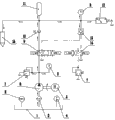
Fig. 1 is a system synthesis structural representation of the present invention;
Fig. 2 is a system start-up pattern diagram of the present invention;
Fig. 3 is a system of the present invention pattern of pressure synoptic diagram;
Fig. 4 is a system of the present invention pressure regulation pattern diagram;
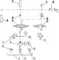
Fig. 5 is a system of the present invention pressurize test pattern synoptic diagram;
Fig. 6 is a system decompression pattern diagram of the present invention;
Fig. 7 is a system standby pattern diagram of the present invention.
Wherein: 1 is main fuel tank, and 2 is liquid level gauge, and 3 is the inlet port filtrator, 4 is thermometer, and 5 is motor, and 6 is oil pump, 7 is surplus valve, and 8 is tensimeter, and 9 is the 3-position 4-way Elactro magnetic commutator, 10 is retaining valve, 11 is reservoir, and 12 is pressure switch, and 13 is hydraulic control one-way valve, 14 is two four-way electromagnetic reversing valves, and 15 is tested element.
Embodiment
The invention provides a kind of test macro of seal element tiny leakage amount, comprise the pressure feed system, compression system, voltage-regulating system, the pressurize test macro, pressure release security system and complete machine control system, wherein said pressure feed system provides the highly pressurised liquid that is higher than test request power for tested element 15, described compression system provides the working environment of a simulation for tested element 15, described voltage-regulating system can accurately be adjusted tested element 15 required pressure difference ring borders, further approach the working pressure environment of tested element 15, described pressurize test macro can be calculated the leakage rate of liquid under the pressurize environment by the pressure change of checking test liquid under the pressurize environment, described compression system comprises a surplus valve 7, two tensimeters 8, a 3-position 4-way Elactro magnetic commutator 9, a retaining valve 10, a reservoir 11, pressure control switch and plurality of pipelines, described voltage-regulating system comprises two surplus valves 7, a 3-position 4-way Elactro magnetic commutator 9, two four-way electromagnetic reversing valves 14, a retaining valve 10, a hydraulic control one-way valve 13, a tensimeter 8, a reservoir 11, the shared surplus valve 7 of compression system and voltage-regulating system wherein, a tensimeter 8, a 3-position 4-way Elactro magnetic commutator 9, a retaining valve 10, a reservoir 11, pressure control switch and respective line, described pressurize test macro comprises two tensimeters 8, a reservoir 11, a retaining valve 10, a hydraulic control one-way valve 13, tested element 15, described pressure release security system comprises a hydraulic control one-way valve 13, two four-way electromagnetic reversing valves 14, a surplus valve 7, described complete machine control system comprises master controller, communication bus and interface circuit, and being distributed in each subsystem parts interior various sensors and electronic control unit, the various sensors of each subsystem inside are connected with master controller by interface circuit with electronic control unit.The pressure source of described pressure feed system can be provided by the variable frequency hydraulic pump that native system carries, and also can be provided by the ambient pressure source by switch.Be provided with filtering system, cooling system and position liquid indicating device in the described reservoir.Described compression system is regulated by the 3-position 4-way Elactro magnetic commutator 9 of master controller control, and the pressurization degree can be regulated arbitrarily.Described voltage-regulating system pressure regulation threshold value is finished by master controller control 3-position 4-way Elactro magnetic commutator 9 and then control hydraulic control one-way valve 13.Described voltage-regulating system comprises return liquid system, is provided with two four-way electromagnetic reversing valves 14 and the surplus valve 7 that prevent system pressure sudden change and pulsation in the described return liquid system.Have only a retaining valve 10 and a hydraulic control one-way valve 13 to be in communication with the outside in the pressure dwelling loop of described pressurize test macro, avoided the system in the pressure maintaining period from revealing, improve precision of measurement, described pressurize test environment has been reserved the adjustable test macro of multiparameter, this system is according to the pressurize sealed volume, test liquid type and unit interval pressure drop-out value etc. can comprehensively be judged the leakage rate of tested element 15, if providing acceptance condition can also directly use as inspection apparatus, pressurize test macro volume needs to adjust according to the leakage rate that tested element 15 allows, and the purpose of adjustment is more targeted when making parameters such as selecting sensor and tensimeter range.Also be provided with leakage reclaim line and inlet port filtrator 3 in this test macro, can carry out recycling for the test liquid that leaks out element.
Workflow of the present invention is as follows:
1. startup test macro
For test macro starts the back principle of work, after the complete machine start button was pressed, the complete machine control system was carried out self check, as the no abnormal start-up routine that then enters of each system as illustrated in fig. 1 and 2.Start oil pump 6 beginning fuel feeding as liquid level gauge 2 and thermometer 4 no abnormal then motor 5 this moment.It is fixed that motor 5 rotating speeds are required according to the complete machine control system by frequency converter, and it is relatively low to reach energy-conservation purpose in general to start rotating speed.Test enters the test pipeline with oil through inlet port filtrator 3 and oil pump 6.At this moment, surplus valve 7 is in the not overflow of aperture minimum state, and test oil is road backflow main fuel tank 1 in 3-position 4-way Elactro magnetic commutator 9, and tensimeter is designated as zero.
2. system enters the pressurized operation state
As shown in figs. 1 and 3 for entering the schematic diagram of pressurized state after the test macro startup, pressurized state is a steps necessary of the whole process of test, when needs are tested tested element 15, need at first tested element 15 clampings to be opened testing button behind measuring head, master controller is finished guidance system sequence of operations such as pressurization, pressure regulation, test and pressure release automatically.
After entering the pressurized operation state, motor 5 is adjusted the pressurization rotating speed automatically according to the pressurization demand, if the test pressure height that in general tested element 15 requires, the pressurization rotating speed is just higher relatively, and test pressure is low, and the pressurization rotating speed is also relatively low.Such design can be shortened the whole test duration effectively, and efficient and energy savings are provided.Under the pressurized state, the spool of 3-position 4-way Elactro magnetic commutator 9 moves to right, and the path that test oil enters test environment is opened, and Hi-pot test this moment oil has been full of the test environment pipeline.When test oil pressure surpassed default test pressure value, 3-position 4-way Elactro magnetic commutator 9 moved to left automatic spool, and this moment, test oil was closed towards the passage of test pipeline, and test oil is back to main fuel tank 1 from scavenge pipe.
3. system enters the pressure regulation state
After pressurized state finished, master controller entered pressure regulation state adjustment test pipeline build-in test oil pressure rapidly with Adjustment System.For entering the schematic diagram of pressure regulation state after the test macro startup, the motor 5 that pressurizes this moment slowly runs to cut down the consumption of energy and to provide hydraulic control one-way valve 13 kinetic energy simultaneously with the utmost point as shown in figs. 1 and 4.3-position 4-way Elactro magnetic commutator 9 spools continue to move to left, and the pressure regulation branch road is opened.According to default pressure limitation, unnecessary test oil will be overflowed through two four-way electromagnetic reversing valves 14 by hydraulic control one-way valve 13 and will be back to main fuel tank 1 from surplus valve 7.Through the adjustment of hydraulic control one-way valve 13, line pressure is accurately positioned in the required pressure value in the test environment, so that enter next test environment.
4. system enters the pressurize test mode
This state is that a most important link also is a link that directly draws the qualification conclusion in the whole workflow.Be depicted as the schematic diagram that enters the pressurize test mode after test macro starts as Fig. 1 and 5, the test oil of this moment is by a retaining valve 10 and hydraulic control one-way valve 13 complete closed, and as not considering the leakage of tested components and parts, the leakage rate that requires system self is zero.Under this state, the method for test has two kinds.A kind of test oil pressure drop-out value that is closed with the unit interval is for adhering to standard, and promptly in the unit official hour, in 5 minutes, the drop-out value of hydraulic pressure must be less than certain and just think that in design load system is qualified; Another kind method is to investigate the time required under the situation of decline unit's pressure, promptly in test environment build-in test oil decline unit pressure, the time required as 1bar.
When carrying out work with first kind of method of testing, master controller picks up counting when test is initial, require at the appointed time as stop timing 5 minutes the time and measure the drop-out value of liquid pressure according to tested element 15, can calculate the leakage rate of tested element 15 by top formula easily.Wherein, the elastic modulus of test liquid can or be looked into the handbook acquisition according to experiment.
5. system enters the pressure release state
After test finishes, after can showing test results, system carries out the pressure release operation automatically so that enter next test link.For entering the schematic diagram of pressure release state after the test macro startup, the motor 5 that pressurizes this moment slowly runs to cut down the consumption of energy and to provide hydraulic control one-way valve 13 kinetic energy simultaneously with the utmost point as shown in figs. 1 and 6.3-position 4-way Elactro magnetic commutator 9 spools move to left, the complete conducting of pressure release branch road, and unnecessary test oil will be overflowed through two four-way electromagnetic reversing valves 14 by hydraulic control one-way valve 13 and will be back to main fuel tank 1 from surplus valve 7.The effect of pressure release operation is to reduce the test environment internal pressure, and tested element 15 for convenience detach reduces operational danger.
6. system standby
After pressure release operation, system need enter a standby environment automatically so that next time test operation can start rapidly.Be depicted as the schematic diagram that enters the pressure release state after test macro starts as Fig. 1 and 7, after the pressure release operation was finished, master controller was adjusted into the standby low-power consumption mode with test macro.This moment, motor 5 and oil pump 6 be with idling pump oil, and it is fixed that motor speed is required according to the complete machine control system by frequency converter, lower rotating speed be consider energy-conservation.Test enters test pipeline through oil through inlet port filtrator 3 and oil pump 6 with oil.At this moment, surplus valve 7 is in the not overflow of aperture minimum state, and test oil is road backflow main fuel tank 1 in 3-position 4-way Elactro magnetic commutator 9, and tensimeter is designated as zero.As need not the use test system for a long time, can directly cut off the power supply for shutting down gets final product.
The superiority of this test macro is the sensitivity of its height.The elastic modulus of test liquid very big all generally, as its K value of oil base test fluid up to 1.4 ~ 2 * 10
3Mpa so instant leakage rate is extremely small, also has been placed to several hundred million times after multiply by K value, is equipped with high-precision pressure sensor again and just can have found out extremely micro-leakage.
In order to improve the accuracy of test macro, necessarily require the internal system self sealss to get well, must not have and leak or from the leakage rate of leakage rate far below tested element 15.In the present invention, specialized designs a retaining valve 10 and 13 pairs of tested formation testings of a hydraulic control one-way valve seal.
Complete machine control system among the present invention will be with pre-set program work, parameter and timing leakage rate situations such as automatic detection time, pressure change, and product more in the past directly detects leakage rate more accurately, efficiently.Compare with the existing technology that directly detects leak materials, the present invention occupies greater advantage on mechanism.
Claims (4)
1. the test macro of a seal element tiny leakage amount, it is characterized in that: comprise the pressure feed system, compression system, voltage-regulating system, the pressurize test macro, pressure release security system and complete machine control system, wherein said pressure feed system provides the highly pressurised liquid that is higher than test request power for tested element, described compression system provides the working environment of a simulation for tested element, described voltage-regulating system can accurately be adjusted tested element required pressure difference ring border, further approach the working pressure environment of tested element, described pressurize test macro can be calculated the leakage rate of liquid under the pressurize environment by the pressure change of checking test liquid under the pressurize environment, described compression system comprises a surplus valve, two pressure transducers, a solenoid directional control valve, a retaining valve, a reservoir, pressure control switch and plurality of pipelines, described voltage-regulating system comprises two surplus valves, two solenoid directional control valves, a retaining valve, a hydraulic control one-way valve, a pressure transducer, a reservoir, described pressurize test macro comprises a pressure transducer, a reservoir, a retaining valve, a hydraulic control one-way valve, an observable tensimeter and tested element, described pressure release security system comprises a hydraulic control one-way valve, a solenoid directional control valve, a surplus valve, described complete machine control system comprises master controller, communication bus and interface circuit, and being distributed in each subsystem parts interior various sensors and electronic control unit, the various sensors of each subsystem inside are connected with master controller by interface circuit with electronic control unit.
2. the test macro of a kind of seal element tiny leakage amount according to claim 1 is characterized in that: the pressure source of described pressure feed system can be provided by the variable frequency hydraulic pump that native system carries, and also can be provided by the ambient pressure source by switch.
3. the test macro of a kind of seal element tiny leakage amount according to claim 1 is characterized in that: be provided with filtering system, cooling system and position liquid indicating device in the described reservoir.
4. the test macro of a kind of seal element tiny leakage amount according to claim 1 is characterized in that: also comprise leakage reclaim line and filtration unit.
Priority Applications (1)
| Application Number | Priority Date | Filing Date | Title |
|---|---|---|---|
| CN201110121689XA CN102288252B (en) | 2011-05-12 | 2011-05-12 | System for testing micro leakage of sealed component |
Applications Claiming Priority (1)
| Application Number | Priority Date | Filing Date | Title |
|---|---|---|---|
| CN201110121689XA CN102288252B (en) | 2011-05-12 | 2011-05-12 | System for testing micro leakage of sealed component |
Publications (2)
| Publication Number | Publication Date |
|---|---|
| CN102288252A true CN102288252A (en) | 2011-12-21 |
| CN102288252B CN102288252B (en) | 2012-11-14 |
Family
ID=45334862
Family Applications (1)
| Application Number | Title | Priority Date | Filing Date |
|---|---|---|---|
| CN201110121689XA Expired - Fee Related CN102288252B (en) | 2011-05-12 | 2011-05-12 | System for testing micro leakage of sealed component |
Country Status (1)
| Country | Link |
|---|---|
| CN (1) | CN102288252B (en) |
Cited By (3)
| Publication number | Priority date | Publication date | Assignee | Title |
|---|---|---|---|---|
| CN106286474A (en) * | 2015-06-08 | 2017-01-04 | 佛山市恒力泰机械有限公司 | A kind of leakage automatic judging method of ceramic brick press hydraulic pressurization element |
| CN110735926A (en) * | 2019-10-16 | 2020-01-31 | 无锡市伊利亚特机械制造有限公司 | sealing system |
| CN112555234A (en) * | 2019-09-10 | 2021-03-26 | 上海中车艾森迪海洋装备有限公司 | Automatic pressure regulating system for regulating oil leakage pressure of underwater operation equipment |
Citations (3)
| Publication number | Priority date | Publication date | Assignee | Title |
|---|---|---|---|---|
| US3312103A (en) * | 1964-03-26 | 1967-04-04 | Kieserling & Albrecht | Hydraulic pressure control apparatus |
| CN201096595Y (en) * | 2007-09-29 | 2008-08-06 | 珠海天威飞马打印耗材有限公司 | Powder hopper hermeticity detection device |
| CN101620023A (en) * | 2009-08-13 | 2010-01-06 | 鲁锋 | Valve detecting system |
-
2011
- 2011-05-12 CN CN201110121689XA patent/CN102288252B/en not_active Expired - Fee Related
Patent Citations (3)
| Publication number | Priority date | Publication date | Assignee | Title |
|---|---|---|---|---|
| US3312103A (en) * | 1964-03-26 | 1967-04-04 | Kieserling & Albrecht | Hydraulic pressure control apparatus |
| CN201096595Y (en) * | 2007-09-29 | 2008-08-06 | 珠海天威飞马打印耗材有限公司 | Powder hopper hermeticity detection device |
| CN101620023A (en) * | 2009-08-13 | 2010-01-06 | 鲁锋 | Valve detecting system |
Cited By (4)
| Publication number | Priority date | Publication date | Assignee | Title |
|---|---|---|---|---|
| CN106286474A (en) * | 2015-06-08 | 2017-01-04 | 佛山市恒力泰机械有限公司 | A kind of leakage automatic judging method of ceramic brick press hydraulic pressurization element |
| CN106286474B (en) * | 2015-06-08 | 2018-03-20 | 佛山市恒力泰机械有限公司 | A kind of leakage automatic judging method of ceramic brick press hydraulic pressurization element |
| CN112555234A (en) * | 2019-09-10 | 2021-03-26 | 上海中车艾森迪海洋装备有限公司 | Automatic pressure regulating system for regulating oil leakage pressure of underwater operation equipment |
| CN110735926A (en) * | 2019-10-16 | 2020-01-31 | 无锡市伊利亚特机械制造有限公司 | sealing system |
Also Published As
| Publication number | Publication date |
|---|---|
| CN102288252B (en) | 2012-11-14 |
Similar Documents
| Publication | Publication Date | Title |
|---|---|---|
| CN100427913C (en) | Equipment for testing valve performance of oil fuel pump | |
| CN203908741U (en) | Leakage detection device | |
| CN103398830B (en) | A kind of grease chamber's sealing leak hunting method of load ratio bridging switch | |
| CN201803832U (en) | Tester using acoustic emission signals to detect valve leakage | |
| CN102768104A (en) | Water dispenser used water system leak detection device and method | |
| CN105387977B (en) | A kind of two chambers, three pressure plot structure for aero-engine installs side leak detection system and method | |
| CN202177417U (en) | Test system for micro-leakage amount of sealing element | |
| CN102288252B (en) | System for testing micro leakage of sealed component | |
| KR101395739B1 (en) | Apparatus and method for detecting leakage of gas meter | |
| CN102278302A (en) | Mechanical seal identification platform and method for reactor coolant pump of million-kilowatt nuclear power station | |
| CN202177402U (en) | Accuracy detection system of micro leakage quantity of fuel injector for hydraulic automobile | |
| CN203081905U (en) | Test bed of valve actuator cylinder | |
| CN205424078U (en) | Quick detecting system of axial deformation of butterfly valve valve plate | |
| CN103926042B (en) | Wastage and sealing simple detection device between oil well pump barrel and plunger | |
| CN104500381A (en) | Performance testing device for oil pump | |
| CN105275921B (en) | Hydraulic air test system | |
| CN202066653U (en) | Automatic oil circuit leakage detection and control system of test bed of vehicle part | |
| CN205280291U (en) | Measurement device for small leakage quantity that lets out of hydraulic component | |
| CN210513586U (en) | Upstream pumping seal test system | |
| CN204514555U (en) | A kind of leak detection system being applied to low-pressure coal saver | |
| CN209247278U (en) | A kind of fluidic medium valve tiny leakage test device | |
| CN204373845U (en) | Tensimeter dynamic pressure fatigue test device | |
| Dindorf et al. | Automatic device for indirect measurement of leakage flow rate in compressed air pipeline | |
| RU2668628C1 (en) | Method of consumption characteristics control for differential-safety devices and installation for method implementation | |
| CN202209242U (en) | Detection system for injection angle of fuel injector of engine |
Legal Events
| Date | Code | Title | Description |
|---|---|---|---|
| C06 | Publication | ||
| PB01 | Publication | ||
| C10 | Entry into substantive examination | ||
| SE01 | Entry into force of request for substantive examination | ||
| C14 | Grant of patent or utility model | ||
| GR01 | Patent grant | ||
| C41 | Transfer of patent application or patent right or utility model | ||
| TR01 | Transfer of patent right |
Effective date of registration: 20151202 Address after: 325000, room 1, building 38, 1132 Dongfang Road, Ouhai Economic Development Zone, Zhejiang, Wenzhou Patentee after: EXCE INTELLIGENT EQUIPMENT WENZHOU CO., LTD. Address before: Dasan Ouhai District 325000 Zhejiang province Wenzhou Higher Education Park Patentee before: Wenzhou University |
|
| CF01 | Termination of patent right due to non-payment of annual fee | ||
| CF01 | Termination of patent right due to non-payment of annual fee |
Granted publication date: 20121114 Termination date: 20170512 |