CN201803832U - Tester using acoustic emission signals to detect valve leakage - Google Patents
Tester using acoustic emission signals to detect valve leakage Download PDFInfo
- Publication number
- CN201803832U CN201803832U CN2010205422897U CN201020542289U CN201803832U CN 201803832 U CN201803832 U CN 201803832U CN 2010205422897 U CN2010205422897 U CN 2010205422897U CN 201020542289 U CN201020542289 U CN 201020542289U CN 201803832 U CN201803832 U CN 201803832U
- Authority
- CN
- China
- Prior art keywords
- valve
- acoustic emission
- test
- reserve tank
- delivery pipe
- Prior art date
- Legal status (The legal status is an assumption and is not a legal conclusion. Google has not performed a legal analysis and makes no representation as to the accuracy of the status listed.)
- Expired - Fee Related
Links
Images


Abstract
The utility model discloses a tester using acoustic emission signals to detect valve leakage, which comprises a liquid storage tank, a pumping unit, a pressure stabilizer, a tested valve, a flow measurer and an acoustic emission detection sensor, the input end of the pumping unit is connected with the liquid storage tank, the output end of the pumping unit is connected with the pressure stabilizer, one end of the tested valve is connected with the pressure stabilizer through a duct, the other end of the tested valve is connected with the inlet of the flow measurer through a duct, the outlet of the flow measurer is communicated with the liquid storage tank, and the acoustic emission detection sensor is mounted on the tested valve. The tester can simulate the actual conditions when various valves are leaked, the characteristics of various acoustic emission signals can be conveniently observed, and the tester can meet the requirements of experiment teaching and experiment exploration.
Description
Technical field
The utility model relates to the testing equipment in the Steam Turbine therrmodynamic system field tests, relates in particular to the test unit that detects valve leak with acoustic emission signal.
Background technology
The employed valve in fuel-burning power plant will bear high temperature and high pressure mostly, if valve internal leaks, not only can the produce power loss, and reduce the efficient of unit, but also can cause thermal power plant's fault to take place frequently, the safety of equipment is constituted a serious threat.If can carry out early stage on-line monitoring and diagnosis to valve leak, degree and development trend that prediction is leaked, on-call maintenance or replacing valve, then can effectively prevent the generation of fault, avoid the expansion of accident, also can make simultaneously power plant carry out repairing in advance and prepare, improve the security and the economy of thermal power plant's operation.The acoustic emission signal pick-up unit is exactly wherein a kind of on-line monitoring and diagnosis device, in order to grasp sound emission signal characteristic and the Changing Pattern thereof that high-temperature high pressure valve leaks, just need test exploration on the valve leak testing table.
The utility model content
The technical problems to be solved in the utility model is to overcome the deficiencies in the prior art, provide a kind of can simulate multiple valve leak the time actual conditions, be convenient to various sound emission signal characteristics observe, satisfy experimental teaching require and test explore require detect the test unit of valve leak with acoustic emission signal.
For solving the problems of the technologies described above, the utility model by the following technical solutions:
A kind of test unit that detects valve leak with acoustic emission signal, comprise liquid reserve tank, pumping unit, voltage stabilizer, test valve, flow measurement device and acoustic emission detecting sensor, the input end of described pumping unit is connected with described liquid reserve tank, the output terminal of pumping unit is connected with described voltage stabilizer, described test valve one end is connected with voltage stabilizer by delivery pipe, the other end is connected with the inlet of described flow measurement device by delivery pipe, the outlet of described flow measurement device is communicated with liquid reserve tank, and described acoustic emission detection sensor is installed on the test valve.
Described test valve two ends and connect and be equipped with damping washer between the delivery pipe.
Be equiped with telescopic joint at least one delivery pipe in the delivery pipe at described test valve two ends.
Described liquid reserve tank is provided with base, and described delivery pipe is fixing by the base supporting.
Be provided with damping ring between described base and the described delivery pipe.
Be equiped with the integrated piece that is communicated with on the delivery pipe between described test valve and the voltage stabilizer, described integrated connection piece is provided with an outlet and a plurality of inlet, described test valve is communicated with the integrated outlet that is communicated with piece, described voltage stabilizer and pumping machine group are communicated with an integrated inlet that is communicated with piece respectively, described integrated connection piece has at least an inlet to be connected with source of the gas, and each inlet is respectively by a valve control break-make.
Described flow measurement device is flow gaging weir or measuring container or float type flow meter.
Be connected with safety valve between described pumping unit and the described voltage stabilizer.
Described liquid reserve tank top is provided with liquid injection port, and the liquid reserve tank bottom is provided with escape hole, and the liquid reserve tank side is equiped with liquid level gauge and cover plate.
Compared with prior art, advantage of the present utility model is:
The test unit that detects valve leak with acoustic emission signal of the present utility model, actual conditions in the time of can simulating multiple valve leak, various sound emission signal characteristics are observed (observation test valve leak amount difference for example, the asynchronous sound emission signal characteristic of leakage point position difference and valve opening, sound emission signal characteristic when the observation interference is less or big), for the sound emission signal characteristic Changing Pattern of grasping valve leak provides test platform, satisfy experimental teaching requirement and test exploration requirement fully, and this apparatus structure is simple, easy to operate, be convenient to promote.Test valve two ends and connect and be equipped with damping washer between the delivery pipe, this damping washer can reduce mechanical noise to be disturbed, reduce the testing valve influence of bound pair acoustic emission detection sensor outdoors, damping washer can be unloaded in the time of need under disturbing bigger situation, testing.Be equiped with telescopic joint on delivery pipe, can carry out dismounting to the test valve very easily by telescopic joint, and the test valve of multiple different sizes can be installed, make the kind of tested valve abundanter, the fault simulation ability is stronger.Delivery pipe is fixing by the base supporting, is provided with damping ring between base and the delivery pipe, can avoid external interference to pass to the test valve through delivery pipe, makes test unit of the present utility model have higher antijamming capability.Be equiped with the integrated piece that is communicated with on the delivery pipe between test valve and the voltage stabilizer, by integrated connection piece can be separately by source of the gas ventilation body (as pressurized air, steam), supply water, supply water with the pumping unit separately with voltage stabilizer separately, can further improve the analog capability of this test unit.Flow measurement device is flow gaging weir or measuring container or float type flow meter, and the concrete kind of flow measurement device can be selected according to the flow size, the sound emission signal characteristic in the time of can observing the water leakage size variation by changing different flowmeters.Be connected with safety valve between pumping unit and the voltage stabilizer, the sound emission signal characteristic in the time of can observing pressure and just change by the triggering pressure of regulating safety valve.The liquid reserve tank top is provided with liquid injection port, can in liquid reserve tank, add water or hydraulic oil by liquid injection port, the liquid reserve tank bottom is provided with escape hole, can be when needing maintenance from escape hole with the liquid reserve tank emptying, the liquid reserve tank side is equiped with liquid level gauge and cover plate, can observe liquid level in the liquid reserve tank by liquid level gauge, can overhaul liquid reserve tank inside opening cover plate after the liquid reserve tank emptying, be provided with filter screen in the liquid reserve tank, be used for the liquid that refluxes is filtered.
Description of drawings
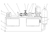
Fig. 1 is a main TV structure synoptic diagram of the present utility model;
Fig. 2 is a plan structure synoptic diagram of the present utility model;
Fig. 3 is a left TV structure synoptic diagram of the present utility model;
Fig. 4 is a hydraulic system synoptic diagram of the present utility model.
Each label is represented among the figure:
1, liquid reserve tank; 2, pumping unit; 3, voltage stabilizer; 4, delivery pipe; 5, test valve; 6, flow measurement device; 7, acoustic emission detection sensor; 8, damping washer; 9, telescopic joint; 10, damping ring; 11, integrated connection piece; 12, liquid injection port; 13, escape hole; 14, liquid level gauge; 15, cover plate; 16, flow gaging weir; 19, safety valve; 20, source of the gas; 21, filter screen; 22, base.
Embodiment
Fig. 1 to Fig. 4 shows a kind of test unit that detects valve leak with acoustic emission signal of the present utility model, comprise liquid reserve tank 1, pumping unit 2, voltage stabilizer 3, test valve 5, flow measurement device 6 and acoustic emission detecting sensor 7, the input end of pumping unit 2 is connected with liquid reserve tank 1, the output terminal of pumping unit 2 is connected with voltage stabilizer 3, test valve 5 one ends are connected with voltage stabilizer 3 by delivery pipe 4, the other end is connected with the inlet of flow measurement device 6 by delivery pipe 4, the outlet of flow measurement device 6 is communicated with liquid reserve tank 1, and other connecting pipeline is arranged in the liquid reserve tank 1 except that delivery pipe 4.Acoustic emission detection sensor 7 is installed on the test valve 5.Liquid reserve tank 1 can pack into water or hydraulic oil, present embodiment is that example describes with the water storage.When using this test unit, by pumping unit 2 water in the liquid reserve tank 1 is sent into voltage stabilizer 3 earlier, stop the running of pumping unit 2 before the beginning testing, and keep hydraulic pressure by voltage stabilizer 3, bump interferences that rub with the electromagnetic interference (EMI) that reduces motor and the machinery of pump, can observe like this disturb than hour sound emission signal characteristic; Also can under the situation that pumping unit 2 is opened, observe the sound emission signal characteristic when disturbing greatly; All right observation test valve 5 leakage rate differences, leakage point position difference and the asynchronous sound emission signal characteristic of valve opening.Actual conditions when the test unit with acoustic emission signal detection valve leak as seen of the present utility model can be simulated multiple valve leak, for the sound emission signal characteristic Changing Pattern of grasping valve leak provides test platform, satisfy experimental teaching requirement and test exploration requirement fully, and this apparatus structure is simple, easy to operate, be convenient to promote.
In the present embodiment, test valve 5 two ends and connect and be equipped with damping washer 8 between the delivery pipe 4, this damping washer 8 is made (as epoxy resin) by nonmetallic materials, can reduce mechanical noise disturbs, reduce the influence of test valve 5 outer bound pair acoustic emission detection sensors 7, damping washer 8 can be unloaded in the time of need under disturbing bigger situation, testing, can make the damping bolt sleeve with same material in addition, be placed on the bolt that connects test valve 5 and delivery pipe 4 flanges with this damping bolt sleeve, prevent that external interference is delivered to test valve 5 by delivery pipe 4 and bolt.Be equiped with telescopic joint 9 at least one delivery pipe 4 in the delivery pipe 4 at test valve 5 two ends, present embodiment is installed this telescopic joint 9 on the delivery pipe 4 that is connected to flow measurement device 6, can carry out dismounting to test valve 5 very easily by this telescopic joint 9, and the test valve 5 of multiple different sizes can be installed, make the kind of tested valve abundanter, the fault simulation ability is stronger.In the present embodiment, liquid reserve tank 1 is provided with base 22, and delivery pipe 4 is fixing by base 22 supportings, is provided with damping ring 10 between base 22 and the delivery pipe 4, can avoid external interference to pass to test valve 5, make test unit of the present utility model have higher antijamming capability through delivery pipe 4.Be equiped with the integrated piece 11 that is communicated with on the delivery pipe 4 between test valve 5 and the voltage stabilizer 3, integrated connection piece 11 is provided with an outlet and a plurality of inlet, in the present embodiment, the inlet of integrated connection piece 11 is provided with three, one of them inlet is connected with source of the gas 20, an inlet connects voltage stabilizer 3, an inlet connects pumping unit 2, the outlet of integrated connection piece 11 is connected with test valve 5, three inlets are respectively by a valve control break-make, can ventilate bodies (as steam by source of the gas 20 separately like this, in teaching test, for security consideration, the compressed air system simulation high temperature and high pressure steam system that can adopt screw-rod air compressor and gas tank to form), supply water with voltage stabilizer 3 separately, supply water with pumping unit 2 separately, further improve the analog capability of this test unit, integrated connection piece 11 can also increase more inlet except that the described structure of present embodiment, to connect more voltage supply equipment (as connecting a plurality of voltage stabilizers 3) according to actual needs.Tensimeter can also be set at integrated connection piece 11 and test between the valve 5, be used to measure hydraulic pressure or air pressure before the test valve 5.Flow measurement device 6 is flow gaging weir 16 or measuring container or float type flow meter, adopt flow gaging weir 16 in the present embodiment, the concrete kind of flow measurement device 6 can be selected according to the flow size, long when the acoustic emission detection time, flow is big and when free-water level (channel flow) is arranged, adopt flow gaging weir 16 to measure; , flow short when the acoustic emission detection time hour adopts volumetric method to measure, and select for use measuring container as flow measurement device 6 this moment; Very big and when being full of pipeline (pressure flow in pipe) when flow, adopt float type flow meter as flow measurement device, the sound emission signal characteristic in the time of can observing the water leakage size variation by changing different flowmeters.Be connected with safety valve 19 between pumping unit 2 and the voltage stabilizer 3, the sound emission signal characteristic in the time of can observing pressure and just change by the triggering pressure of regulating safety valve 19.Liquid reserve tank 1 top is provided with liquid injection port 12, can in liquid reserve tank 1, add water or hydraulic oil by liquid injection port 12, liquid reserve tank 1 bottom is provided with escape hole 13, can be when needing maintenance from escape hole 13 with liquid reserve tank 1 emptying, liquid reserve tank 1 side is equiped with liquid level gauge 14 and cover plate 15, can observe liquid level in the liquid reserve tank 1 by liquid level gauge, can overhaul liquid reserve tank 1 inside opening cover plate 15 after liquid reserve tank 1 emptying, be provided with filter screen 21 in the liquid reserve tank 1, be used for the liquid that refluxes is filtered.
Above-mentioned is preferred embodiment of the present utility model, is not the utility model is done any pro forma restriction.Though the utility model discloses as above with preferred embodiment, yet be not in order to limit the utility model.Any those of ordinary skill in the art, under the situation that does not break away from the technical solutions of the utility model scope, all can utilize the technology contents of above-mentioned announcement that technical solutions of the utility model are made many possible changes and modification, or be revised as the equivalent embodiment of equivalent variations.Therefore, every content that does not break away from technical solutions of the utility model, all should drop in the scope of technical solutions of the utility model protection any simple modification, equivalent variations and modification that above embodiment did according to the utility model technical spirit.
Claims (10)
1. test unit that detects valve leak with acoustic emission signal, it is characterized in that: comprise liquid reserve tank (1), pumping unit (2), voltage stabilizer (3), test valve (5), flow measurement device (6) and acoustic emission detecting sensor (7), the input end of described pumping unit (2) is connected with described liquid reserve tank (1), the output terminal of pumping unit (2) is connected with described voltage stabilizer (3), described test valve (5) one ends are connected with voltage stabilizer (3) by delivery pipe (4), the other end is connected with the inlet of described flow measurement device (6) by delivery pipe (4), the outlet of described flow measurement device (6) is communicated with liquid reserve tank (1), and described acoustic emission detection sensor (7) is installed on the test valve (5).
2. according to claim 1ly detect the test unit of valve leak, it is characterized in that with acoustic emission signal: described test valve (5) two ends and connect and be equipped with damping washer (8) between the delivery pipe (4).
3. the test unit with acoustic emission signal detection valve leak according to claim 1 and 2 is characterized in that: be equiped with telescopic joint (9) at least one the delivery pipe (4) in the delivery pipe (4) at described test valve (5) two ends.
4. the test unit with acoustic emission signal detection valve leak according to claim 1 and 2, it is characterized in that: described liquid reserve tank (1) is provided with base (22), and described delivery pipe (4) is fixing by base (22) supporting.
5. the test unit with acoustic emission signal detection valve leak according to claim 3, it is characterized in that: described liquid reserve tank (1) is provided with base (22), and described delivery pipe (4) is fixing by base (22) supporting.
6. the test unit with acoustic emission signal detection valve leak according to claim 5 is characterized in that: be provided with damping ring (10) between described base (22) and the described delivery pipe (4).
7. the test unit that detects valve leak with acoustic emission signal according to claim 6, it is characterized in that: be equiped with the integrated piece (11) that is communicated with on the delivery pipe (4) between described test valve (5) and the voltage stabilizer (3), described integrated connection piece (11) is provided with an outlet and a plurality of inlet, described test valve (5) is communicated with the integrated outlet that is communicated with piece (11), described voltage stabilizer (3) and pumping unit (2) are communicated with an integrated inlet that is communicated with piece (11) respectively, described integrated connection piece (11) has at least an inlet to be connected with source of the gas (20), and each inlet is respectively by a valve control break-make.
8. the test unit with acoustic emission signal detection valve leak according to claim 7, it is characterized in that: described flow measurement device (6) is flow gaging weir (16) or measuring container or float type flow meter.
9. the test unit with acoustic emission signal detection valve leak according to claim 8 is characterized in that: be connected with safety valve (19) between described pumping unit (2) and the described voltage stabilizer (3).
10. the test unit that detects valve leak with acoustic emission signal according to claim 9, it is characterized in that: described liquid reserve tank (1) top is provided with liquid injection port (12), liquid reserve tank (1) bottom is provided with escape hole (13), liquid reserve tank (1) side is equiped with liquid level gauge (14) and cover plate (15), is provided with filter screen (21) in the liquid reserve tank (1).
Priority Applications (1)
| Application Number | Priority Date | Filing Date | Title |
|---|---|---|---|
| CN2010205422897U CN201803832U (en) | 2010-09-26 | 2010-09-26 | Tester using acoustic emission signals to detect valve leakage |
Applications Claiming Priority (1)
| Application Number | Priority Date | Filing Date | Title |
|---|---|---|---|
| CN2010205422897U CN201803832U (en) | 2010-09-26 | 2010-09-26 | Tester using acoustic emission signals to detect valve leakage |
Publications (1)
| Publication Number | Publication Date |
|---|---|
| CN201803832U true CN201803832U (en) | 2011-04-20 |
Family
ID=43873332
Family Applications (1)
| Application Number | Title | Priority Date | Filing Date |
|---|---|---|---|
| CN2010205422897U Expired - Fee Related CN201803832U (en) | 2010-09-26 | 2010-09-26 | Tester using acoustic emission signals to detect valve leakage |
Country Status (1)
| Country | Link |
|---|---|
| CN (1) | CN201803832U (en) |
Cited By (9)
| Publication number | Priority date | Publication date | Assignee | Title |
|---|---|---|---|---|
| CN104180168A (en) * | 2014-08-25 | 2014-12-03 | 中国石油天然气股份有限公司 | Device and method for inner leakage detection of two-channel natural gas pipeline ball valve |
| CN105953987A (en) * | 2016-04-18 | 2016-09-21 | 中国石油化工股份有限公司 | Valve inner leakage testing simulating device and gas valve inner leakage rate acoustic emission diagnosis method thereof |
| CN106104246A (en) * | 2014-03-26 | 2016-11-09 | 通用显示器公司 | Ultrasonic gas leak detector and method of testing |
| CN108845038A (en) * | 2018-07-04 | 2018-11-20 | 荆州市世纪派创石油机械检测有限公司 | A kind of valve water test unit and test method |
| CN109696282A (en) * | 2019-01-22 | 2019-04-30 | 中国海洋石油集团有限公司 | Deep water process facility acoustic emission detection system |
| CN112012984A (en) * | 2020-09-21 | 2020-12-01 | 中国人民解放军海军工程大学 | Hydraulic slide valve internal leakage acoustic emission detection experimental device and using method thereof |
| CN112781860A (en) * | 2019-11-06 | 2021-05-11 | 中国石油化工股份有限公司 | Gas-liquid two-phase simulation test device and method for valve internal leakage |
| US20220057774A1 (en) * | 2018-09-19 | 2022-02-24 | Hypertherm, Inc. | Multi-sensor analysis and data point correlation for predictive monitoring and maintenance of a pressurized fluid cutting system |
| CN114252207A (en) * | 2021-12-21 | 2022-03-29 | 福州大学 | Acoustic emission signal data acquisition method for leakage positioning of steel storage tank |
-
2010
- 2010-09-26 CN CN2010205422897U patent/CN201803832U/en not_active Expired - Fee Related
Cited By (12)
| Publication number | Priority date | Publication date | Assignee | Title |
|---|---|---|---|---|
| CN106104246A (en) * | 2014-03-26 | 2016-11-09 | 通用显示器公司 | Ultrasonic gas leak detector and method of testing |
| CN104180168A (en) * | 2014-08-25 | 2014-12-03 | 中国石油天然气股份有限公司 | Device and method for inner leakage detection of two-channel natural gas pipeline ball valve |
| CN105953987A (en) * | 2016-04-18 | 2016-09-21 | 中国石油化工股份有限公司 | Valve inner leakage testing simulating device and gas valve inner leakage rate acoustic emission diagnosis method thereof |
| CN105953987B (en) * | 2016-04-18 | 2018-12-25 | 中国石油化工股份有限公司 | Leak rate sound emission diagnostic method in a kind of valves leakage test simulator and its gas valve |
| CN108845038A (en) * | 2018-07-04 | 2018-11-20 | 荆州市世纪派创石油机械检测有限公司 | A kind of valve water test unit and test method |
| CN108845038B (en) * | 2018-07-04 | 2020-10-09 | 荆州市世纪派创石油机械检测有限公司 | Valve hydrostatic test device and test method |
| US20220057774A1 (en) * | 2018-09-19 | 2022-02-24 | Hypertherm, Inc. | Multi-sensor analysis and data point correlation for predictive monitoring and maintenance of a pressurized fluid cutting system |
| CN109696282A (en) * | 2019-01-22 | 2019-04-30 | 中国海洋石油集团有限公司 | Deep water process facility acoustic emission detection system |
| CN112781860A (en) * | 2019-11-06 | 2021-05-11 | 中国石油化工股份有限公司 | Gas-liquid two-phase simulation test device and method for valve internal leakage |
| CN112012984A (en) * | 2020-09-21 | 2020-12-01 | 中国人民解放军海军工程大学 | Hydraulic slide valve internal leakage acoustic emission detection experimental device and using method thereof |
| CN114252207A (en) * | 2021-12-21 | 2022-03-29 | 福州大学 | Acoustic emission signal data acquisition method for leakage positioning of steel storage tank |
| CN114252207B (en) * | 2021-12-21 | 2024-01-02 | 福州大学 | Acoustic emission signal data acquisition method for steel storage tank leakage positioning |
Similar Documents
| Publication | Publication Date | Title |
|---|---|---|
| CN201803832U (en) | Tester using acoustic emission signals to detect valve leakage | |
| CN103306968B (en) | transformer oil pump test device and test method thereof | |
| CN207263399U (en) | A kind of multistation valve airtight detection apparatus | |
| CN103471787B (en) | The analogue means and its verification method of generator system of nuclear power station | |
| CN108050394A (en) | Fuel gas pipeline leakage based on sound pressure signal identification detects positioning experiment platform | |
| CN202073872U (en) | Driving experiment device of hydraulic motor for airplane generator | |
| CN107631973A (en) | A kind of same apparatus test device of Oil in Super-low Permeability rock sample perm-plug method multi-method | |
| CN203335372U (en) | Transformer oil pump testing device | |
| CN113720555A (en) | Device and method for detecting internal leakage of ball valve of oil and gas pipeline | |
| CN203069372U (en) | Valve testing device in vacuum environment | |
| CN201876391U (en) | Test bench for testing water pressure strength of cylinder | |
| CN205424078U (en) | Quick detecting system of axial deformation of butterfly valve valve plate | |
| CN105181271B (en) | Bleeder and test method for line leakage system performance testing | |
| CN204458305U (en) | A kind of detection facility of Double-liquid mud-injection pump | |
| CN103852224A (en) | Fuel gas watchcase leakage detection device and detection method | |
| CN201716165U (en) | Gas tightness detecting device | |
| CN209055285U (en) | A kind of experimental rig for examining valve high-low pressure to seal | |
| CN208420321U (en) | Safety valve testing equipment | |
| CN202252872U (en) | Underwater gas transmission pipeline leakage detection performance evaluating experimental platform | |
| CN205349686U (en) | Reprocess latent water pump performance detection device | |
| KR101195493B1 (en) | The apparatus for leaking check of hydraulic and pneumatic components | |
| CN201852684U (en) | Air permeability test instrument | |
| CN108760271B (en) | Safety valve opening and closing pressure testing device and method for simulating actual working conditions | |
| CN208223413U (en) | A kind of pipeline leakage testing imitative experimental appliance based on fiber-optic grating sensor | |
| CN208476303U (en) | A kind of closed mixing device device for detecting performance of carbon dioxide |
Legal Events
| Date | Code | Title | Description |
|---|---|---|---|
| C14 | Grant of patent or utility model | ||
| GR01 | Patent grant | ||
| C17 | Cessation of patent right | ||
| CF01 | Termination of patent right due to non-payment of annual fee |
Granted publication date: 20110420 Termination date: 20110926 |