CN1022277C - Variable speed controlled induction motor - Google Patents
Variable speed controlled induction motor Download PDFInfo
- Publication number
- CN1022277C CN1022277C CN87104033A CN87104033A CN1022277C CN 1022277 C CN1022277 C CN 1022277C CN 87104033 A CN87104033 A CN 87104033A CN 87104033 A CN87104033 A CN 87104033A CN 1022277 C CN1022277 C CN 1022277C
- Authority
- CN
- China
- Prior art keywords
- stator
- winding
- phase
- rotor
- stators
- Prior art date
- Legal status (The legal status is an assumption and is not a legal conclusion. Google has not performed a legal analysis and makes no representation as to the accuracy of the status listed.)
- Expired - Lifetime
Links
Images


Classifications
-
- H—ELECTRICITY
- H02—GENERATION; CONVERSION OR DISTRIBUTION OF ELECTRIC POWER
- H02P—CONTROL OR REGULATION OF ELECTRIC MOTORS, ELECTRIC GENERATORS OR DYNAMO-ELECTRIC CONVERTERS; CONTROLLING TRANSFORMERS, REACTORS OR CHOKE COILS
- H02P7/00—Arrangements for regulating or controlling the speed or torque of electric DC motors
-
- H—ELECTRICITY
- H02—GENERATION; CONVERSION OR DISTRIBUTION OF ELECTRIC POWER
- H02K—DYNAMO-ELECTRIC MACHINES
- H02K16/00—Machines with more than one rotor or stator
-
- H—ELECTRICITY
- H02—GENERATION; CONVERSION OR DISTRIBUTION OF ELECTRIC POWER
- H02K—DYNAMO-ELECTRIC MACHINES
- H02K17/00—Asynchronous induction motors; Asynchronous induction generators
- H02K17/02—Asynchronous induction motors
- H02K17/34—Cascade arrangement of an asynchronous motor with another dynamo-electric motor or converter
- H02K17/36—Cascade arrangement of an asynchronous motor with another dynamo-electric motor or converter with another asynchronous induction motor
-
- H—ELECTRICITY
- H02—GENERATION; CONVERSION OR DISTRIBUTION OF ELECTRIC POWER
- H02P—CONTROL OR REGULATION OF ELECTRIC MOTORS, ELECTRIC GENERATORS OR DYNAMO-ELECTRIC CONVERTERS; CONTROLLING TRANSFORMERS, REACTORS OR CHOKE COILS
- H02P5/00—Arrangements specially adapted for regulating or controlling the speed or torque of two or more electric motors
- H02P5/74—Arrangements specially adapted for regulating or controlling the speed or torque of two or more electric motors controlling two or more ac dynamo-electric motors
Abstract
A motor has a rotor (8) formed in one piece and a plurality of stators (24,25), the rotor having a plurality of rotor cores (2,3) and a plurality of conductive members (5) interconnected and the stators having respective stator windings (22,23). The stator windings are connected in series, the rotor conductive members are short-circuited by connecting members (r) at an air space or a non-magnetic core portion disposed between the rotor cores, and at least one of the plurality of stators is associated with a phase shifter providing the voltage of a given phase to the stator windings, whereby the rotational speed can be controlled easily over a wide range with excellent torque characteristics and efficiency.
Description
The invention relates to a kind of induction motor of adjustable speed, this induction motor has good torque characteristics, and efficient height, rotating speed are easy to regulate.
One of general method of regulating the induction motor rotating speed is the frequency that changes power supply.Though this method can be in wide speed range continuous speed adjustment, need the frequency converter of a high price.In addition, this frequency converter may produce higher harmonics noise and other electromagnetic wave when alternating current being transformed into direct current and being transformed into alternating current again, these higher harmonics noises and electromagnetic wave will produce various higher harmonics noise problem if flow into industrial power circuit, make electronic computer or other electronic equipment misoperation, make capacitor heating or the like.The higher harmonics noise problem is to solve by suitable high frequency filter is set, but the expense of this respect also is very big.And this method also has such shortcoming, promptly usually during the motor low-speed running efficient not high.
The method that changes its number of poles in the induction motor operation process can be regulated the rotating speed of induction motor really, but that can only be step speed regulation, thereby this speed governing is both discontinuous also unsmooth.
The method that changes supply voltage on the contrary can reach the purpose of continuous speed adjustment.But this method has a shortcoming, and efficient was low when promptly motor turned round in low-speed range.
Auxiliary resistance is easier to carry out continuous speed adjustment with the method that changes revolutional slip in the change access wound rotor formula motor, but owing to inserted a resistance from the outside by brush and slip ring in the rotor winding circuit, such shortcoming is just arranged, promptly need these brushes and slip ring are regularly checked and careful maintenance.Such problem is arranged in cage rotor formula induction motor: it can not adopt the method that changes auxiliary resistance to carry out speed governing.
The prior art of attempting to address the above problem has really.For example, uncensored No. 29005/1979 Japan Patent has openly just disclosed a kind of like this device, in this device, each mouse cage conductor system configuration like this, they are extended along a pair of rotor core, again the short-circuited conducting sleeve short circuit is used at these conductor two ends respectively, disposed a high resistance resistor in addition by this way, make the conductor middle part of each mouse cage conductor between this two rotor core be in the short circuit state.On the stator that separates with corresponding each rotor core, be provided with some windings.This cage rotor induction motor is when starting, and the phase phasic difference 180 between each stator winding is spent, but in the running after motor starting, each phase place becomes homophase each other after paraphase.Since the phase-shifted during motor starting between the stator winding 180 degree, starting torque increases, thereby has improved the starting characteristic of motor.But under the normal operation condition, because each stator winding is in same-phase, motor turns round under normal torque characteristics.Therefore, although can think that starting characteristic makes moderate progress, the rotating speed of this motor is nonadjustable, thereby can not be as the drive motor of burden requirement speed change.
Uncensored No. 29005/1979 Japan Patent openly comprises such example: from starting carry out the transition to as the practice that do not adopt this example for relaxing motor that torque changes caused vibration suddenly when running well, make its each stator winding short time series connection receive on the power circuit, arrive an intermediate steps of full load running as motor with this.The phase shift that this scheme is confined to rotating magnetic field is the situation of 0 degree or 180 degree, and its purpose is anything but for speed change.When converting series wiring to, the voltage that is added on the stator reduces by half, and in other words, torque reduces to 1/4.Obviously can not carry out speed governing with this disclosed scheme of application for patent of having announced.
Therefore, though uncensored No. 29005/1979 Japan Patent has openly been quoted the practice that is connected in series, the statement: " ... can be used as intermediate steps make being connected of stator winding and power supply circuits be connected in series and be connected in parallel between the switching ", but what must consider is, thisly be connected in series irrelevantly, also be helpless to reach the purpose of speed governing with the purpose of speed governing.
Uncensored No. 86807/1974 Japan Patent has come out with a kind of asynchronous motor with cage rotor and multi phase stator winding.This motor comprises some buss, short circuit end ring and ferromagnetic layer.Stator is divided into first winding and second winding.The coaxial configuration of these first and second windings is adjoined each other, and adjoins the variant part of rotor, can supply with the alternating current of same frequency.The device of using by stator second winding change electric energy that induction produces in the rotor winding also is equipped with.No matter this motor can produce phase difference with mechanical means or electric approach between two divided portion of stator, and can be with the rotational speed regulation of rotor to a certain degree.But the phase angle between two divided portion of stator was in during the same-phase, the torque of motor was so little, so that the load of motor is when increasing, and motor stops at once, and this makes motor impracticable.Therefore this motor is not suitable for the occasion that motor needs repeatedly starting frequently to stop under loading condition, and in other words, this motor also can't resolve the problems referred to above.
The objective of the invention is to solve the problems referred to above that prior art exists, even reach above-mentioned uncensored No. 29005/1979 and No. 86807/1974 Japan Patent are openly combined the benefit that also is beyond one's reach, for example, obtain special torque characteristics, in wide speed regulating range, can adjust any required rotating speed in the stepless speed control mode, and can be under any desirable torque starting motor or the like.Speed governing induction motor of the present invention, the torque characteristics excellence, the efficient height, this is because the present invention causes due to the rated current that is applied when being equivalent to motor full load running from starting to full load running to have applied greatly in the whole wide range of speeds at motor.
But variable speed controllable induction motor order phase power supply of the present invention also can connect three phase mains and uses.The pattern of rotor can be any kind usually, for example mouse-cage type, double squirrel-cage, deep trouth mouse-cage type, special mouse-cage type or winding-type etc.Conductor of mentioning in the specification of the present invention or conducting element typically refer to those and are configured in conductor in the cage rotor iron core or conducting element and the winding on the wound rotor iron core.
Comprise a rotor, a plurality of stator, some Connection Elements and phase changer according to variable speed controllable induction motor provided by the invention.Rotor is made an integral body, has a plurality of rotor cores, and the each interval preset distance is contained on the common axis, and rotor also has a plurality of conducting elements; Be interconnected with one another, and be contained in respectively in each rotor core.Each stator and row arrangement, the rotor core around facing separately is wound with the stator winding that is connected in series respectively on it.Each Connection Element is at the air gap place or be configured in the non-magnetic core piece place short circuit conducting element in each rotor core gap.Phase changer provide towards a plurality of stators one of them conducting element part induced voltage and towards the phase difference between the induced voltage of wherein another the conducting element counterpart of stator.
According to the present invention, the rotating speed of rotor can be regulated by following array apparatus: one of them device can make the magnetic line of force in the magnetic field that produces between each stator and the rotor be offset, another device is then responded to the voltage that produces in order to control on each rotor conductiving element, thereby makes its variation according to magnetic field phase shift increase or reduce.
The configuration mode that each winding is connected in series on a plurality of stators and a plurality of conductive member are contained in a plurality of rotor cores the configuration mode that the Connection Element short circuit by separately gets up following two effects.Effect be flow into rotor conductiving element, according to this conducting element corresponding to the part of its stator separately on the magnitude of current of induced voltage all become equal.Another effect is that the electric current of the vector difference that causes corresponding to the phase difference by each voltage between each stator is flowed through each Connection Element of a plurality of rotor conductiving element short circuits.Utilize the cooperative effect of these two effects, just controlling resistance is pressed the influence degree of each voltage phase difference σ to electric current fully.In other words, under any revolutional slip, change phase difference σ just can control flows through the ratio of the electric current of the rotor conductiving element and the Connection Element of flowing through.Therefore, phase difference σ is transferred the function that to stablize each Connection Element of each rotor conductiving element of control connection when turning down greatly by desirable amount, thereby not only when motor starting, and from low-speed running in the wide speed range that runs up, can both obtain big and stable torque, thereby improve the gross efficiency of motor.
Fig. 1 is the cross sectional side view of induction motor of the present invention.
Fig. 2 is the drawing in side sectional elevation of each stator tumbler.
Fig. 3 is that the part of each stator tumbler is cut top view open.
Fig. 4 is the winding diagram that each stator winding is connected in series.
Fig. 5 is the relation curve of revolutional slip and active power.
Fig. 6 is the equivalent circuit diagram of rotor.
Fig. 7 is the equivalent circuit diagram of the rotor seen from stator side.
Fig. 8 be a plurality of conducting elements respectively by each Connection Element short circuit, under the situation that each stator winding is connected in series, the relation curve of revolutional slip and torque.
Fig. 9 is that each stator winding is connected in parallel under the situation on the power line received the relation curve of revolutional slip and torque.
Figure 10 be a plurality of windings on stator separately, number of poles can be with the winding diagram under each switch selection situation in addition.
Figure 11 is that stator poles is the revolutional slip under four and eight situations and the relation curve of torque.
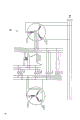
Figure 12 is the winding diagram that expression constitutes the phase change-over switch connected mode of each stator winding phase shift device.
Figure 13 is the phase shift principle of device schematic diagram that is constituted by a single-phase transformer and a plurality of phase change-over switch.
Figure 14 is the phase shift principle of device schematic diagram that is made of an induction voltage regulator.
Figure 15 is the winding diagram that the wiring of stator winding is changed between delta connection and star connection with some switches.
Figure 16 and 17 is relation curves of revolutional slip and torque.
Figure 18 is the phantom that installs the rotor of some resistive elements between a plurality of conducting elements additional.
Figure 19 is the induction motor of the present invention block diagram of control automatically.
Referring now to Fig. 1 to Figure 19 some embodiment of the present invention are described.
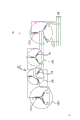
Below with reference to Fig. 1 to Fig. 4 first embodiment is described.Among Fig. 1 and Fig. 3, numbering 1 expression induction motor is promptly introduced its configuration mode below.Rotor core 2 and 3 is installed on the armature spindle across a certain distance, and 9 of non-magnetic core pieces are plugged between rotor core 2 and 3.A plurality of conducting elements 5 are configured on rotor core 2 and 3, the connection that is one another in series, thus form an integral rotor 8.Therefore each conducting element 5 two ends is one another in series, by short-circuited conducting sleeve 6 and 7 short circuit in addition.Rotor core 2,3 and non-magnetic core piece 9 have air channel 12, and this air channel extends to the end 10 and 11 of rotor 8.12 neighborings to rotor 8 are extended with a plurality of air channel hole 13(and see Fig. 2 from the air channel).Resistor or resistive element that each Connection Element r(is promptly made by nickel filament, carbon steel, conductivity ceramics etc.) will be arranged on each conducting element 5 short circuits on the rotor 8 at position between non-magnetic core piece 9 between rotor core 2 and 3, all electric currents with any phasor difference are promptly flowed through on this Connection Element r.Can be clear that from Fig. 1 and Fig. 3 bearing bracket stand 15,16 is fixed on the intercell connector 17 with nut 18 at cylindrical support 14 two ends, so that form a black box.Rotor 8 two ends all are provided with cooling fan 19,20, and armature spindle 4 two ends by bearing 21 axial support, and 21 on bearing is configured on separately the bearing bracket stand 15,16, thereby armature spindle 4 can freely be rotated.
Pulse motor 35 is contained in support 14 outsides, and first driven wheel 36 and the travelling gear 34 that form a unit are fixedly mounted on the driving shaft.Bearing bracket stand 32 is contained in support 14 outsides, is supporting the power transmission shaft 29 that the travelling gear 30 and second driven wheel 31 are housed on it rotationally.First driven wheel 36 and second driven wheel 31 put in the support 14 by the aperture 37 that is located on the support 14, and respectively with first stator 24 on gear 33A and the gear 33B on second stator 25 engagement.Under this configuration mode, first stator 24 and second stator 25 rotate with respect to rotor 8 by means of pulse motor 35 runnings are coaxial.Phase shift device 38 is made of first stator 24 and second stator 25.Numbering 39 expressions are located at the exhaust outlet of support 14 neighboring parts, and numbering 40 expressions are located at the hole, air channel on the bearing bracket stand 15,16.
Referring now to Fig. 4, introduces respectively the mode of connection of the winding 22,23 on first stator 24 and second stator 25.The all windings 23 that become star connection to be arranged on second stator 25 are connected in series with first stator, 24 corresponding windings 22 respectively, receive on the power supply then.In other words, terminal A, B, the C of first stator, 24 windings 22 receives respectively on three-phase industrial power line A, B, the C, terminal a, the b of winding 22, c receive respectively on terminal A, B, the C of second stator, 25 windings 23, terminal a, the b of winding 23, the c short circuit that links together.
Have a talk the below in a manner described operation of motor of configuration.
When electric energy is added to each winding 22 of first stator 24 from the three-phase industrial power, just produce rotating magnetic field around the stator 24,25, then there is electric current to flow through on each conducting element 5 of rotor 8, thus rotor is turned over.When second stator 25 was zero with respect to the amount of spin of first stator 24, the magnetic flux of the rotating magnetic field that produces around each stator 24,25 did not have phase shift.Therefore, as the back will be spoken of, there is not electric current to flow through on resistive element or the Connection Element r, thereby become the same with conventional induction motor of torque characteristics.
Pulse motor 35 running of having a talk and then, first stator 24 and second stator 25 operational circumstances during respectively along θ phase angle of counter-rotation.Constitute first stator 24 of phase shift device 38 and the rotating magnetic field that second stator 25 is produced, its magnetic flux phi
1, Φ
2Phase place can be offset a θ angle, thereby the voltage that first stator 24 and second stator 25 is responded to produce on rotor 8 conducting elements 5
 1,
2, its phase place also is offset a θ angle.Supposition now is as if the voltage that induces on
1,
2, its phase place also is offset a θ angle.Supposition now is as if the voltage that induces on rotor 8 conductive members 5 with second stator 25
2Be benchmark, then this voltage
 2=SE.Here S is a revolutional slip, and E is that revolutional slip equals 1 o'clock inductive voltage value.So the induced voltage of
 first stator 24 on conducting element 5
 1For
1=SE ε
J θ
1For
1=SE ε
J θ
The revolutional slip S of rotor 8 and be input to relation between the active power of rotor when the curve representation of Fig. 5 does not install resistive element r with conducting element 5 short circuits additional at non-magnetic core piece 9 positions.Should be noted that, when the phase difference θ between the magnetic field that stator 24,25 produces is O when spending, active power P maximum, when 0<θ<180, active power P reduces.If the resistance value and the resistance value of resistive element 5 are expressed as R and L respectively, the angular frequency of power supply is ω, and then revolutional slip is S=(R/ ω L) time, active power P maximum.
Exist certain proportionate relationship between the driving torque of active power P and induction motor.Therefore, handle pulse motor 35 and first stator 24 and second stator 25 that constitute phase shift device 38 are turned over, just can regulate the voltage of induction on the conducting element 5, thus the rotating speed of smooth adjustment rotor 8.
When rotor 8 each conducting element 5 are respectively R from each resistance value of short-circuited conducting sleeve 6,7 to Connection Element r
1, R
2, inductance is respectively L
1, L
2, angular frequency is ω, when the resistance value of the resistive element of each conducting element 5 of short circuit was r, the equivalent electric circuit of rotor 8 was as shown in Figure 6.Symbol I
1, I
2, I
3Represent each electric current of flowing through respectively about branch road.
When becoming equivalent circuit transformation shown in Figure 6 from equivalent electric circuit that two stators, 24,25 1 sides are seen, this equivalent electric circuit as shown in Figure 7.Work as R
1=R
2, L
1=L
2, during phase difference θ=0 °, the electric current I of the resistive element r that flows through
3(=I
1-I
2) vanishing.In other words, there is not current direction resistive element r.This means, when θ=0 °, the same when the value of torque T does not exist with resistive element r '.Therefore, under the situation of θ=0 °, the torque characteristics of motor is the same with conventional induction motor.
Secondly, work as R
1=R
2, L
1=L
2, and during phase difference θ=180 °, the electric current I of the resistive element r that flows through
3(=I
1-I
2) become 2I
2Like this, make the rotor resistance device in the conventional induction motor meet R
1=R
2During the condition of=R, its effect is equivalent to R and is increased to R+2r.
When rotor 8 rotated, cooling fan 19,20 sucked air in the support 14 by the hole, air channel 40 that is located on the bearing bracket stand 15,16, and air directly cools off first and second stators 24,25 and winding 22,23 thereof.Rotor core 2,3, conducting element 5, resistive element r etc. are also by cooling off via the air of hole, air channel 13 by air channel 12.This cooling effect is guaranteed that each assembly of motor is stable and is played a role.
First and second stators the 24, the 25th make it clockwise or rotate counterclockwise by being switched on or switched off pulse motor 35, but this is not limited to and uses pulse motor 35, other drive unit, (for example, but the servomechanism of motor with reciprocating movement, employing air pressure or hydraulic cylinder etc.) also can reach same purpose, in addition also can be with some lever operated.Among each embodiment that here enumerates, first stator 24 and second stator, 25 boths are rotary, but also can adopt the mode that only makes their one of them rotations, can obtain good effect equally.About discharging and locking the mechanism that relevant stator is used, can adopt common those mechanisms that can get.
The be connected in series effect of connection of the winding 22,23 on first and second stators 24,25 of having a talk now.
Because stator winding the 22, the 23rd is connected in series, thereby when electric current when the three-phase industrial power is added on the winding 22, the electric current of winding 22 and winding 23 of flowing through respectively equates, and both made each resistance value of winding 22,23 that any difference is arranged, or two stator 24,25 any difference is arranged on volume, can not be affected yet.Therefore, first stator 24 and second stator 25 induce on each conducting element 5 of rotor 8 that current amount flowing is equal to each other and is constant on this conductive member.This effect, add the effect that the current value of the conducting element 5 of the inflow rotor 8 that is produced by first stator 24 and the induction of second stator 25 becomes equal corresponding to the slip between first stator 24 that constitutes the phase shift device and second stator 25 (promptly phase shift that the rotating magnetic field magnetic flux produced), also have two stators 24, the vector difference electric current that phase difference between 25 magnetic fields that produced causes is flowed through the effect of each resistive element of 5 connections of each conducting element or short circuit, these effects add and have just produced cooperative effect together, thereby shown in the torque characteristic curve of Fig. 8, might raise the efficiency, and in the range of speeds separately, produce high driving torque.Therefore, both made at motor and continued under the situation of on-load, also may be in any given range of speeds starting motor easily, and give desired starting characteristic smooth starting of constant load or high torque (HT) starting according to a certain, thereby this motor can be in order to being engaged in multiple work, and be applicable to the work that requires repeatedly Fraquent start and stop.As mentioned above, as long as control phase moves, and the increase of control flows electric current in rotor 8 conducting elements 5 and minimizing (this is undertaken by gearshift 38) both can change the rotating speed of rotor 8.
Otherwise, when the winding 22,23 of first stator 24 and second stator 25 respectively and when being connected on the three-phase industrial power, owing to the voltage on the winding 22,23 that is added to first stator 24 and second stator 25 equates, two stators 24,25 are responded to the voltage that produces and are equated on each conducting element 5 of rotor 8, the electric current of each resistive element r is directly proportional with (1/2) * (first and second stators 24,25 are the differential voltage between the voltage that induction on the rotor conductiving element 5 produces respectively)+(resistance value of resistive element r) substantially but the phase difference P θ of these voltages flows through.But in each conducting element 5 of rotor 8, except that the electric current that flows into resistive element r, the electric current that stream has with (superimposed voltage that first and second stators are responded on rotor conductiving element)+(impedance of each rotor conductiving element) is directly proportional also.The vanishing when P θ=π of this superimposed voltage reaches maximum when P θ=0, and the impedance of each conducting element of rotor is owing to be made up of resistance and auxilliary leakage reactance, thereby it becomes with revolutional slip.Therefore, by being configured in current convection on the resistive element r between each conducting element 5, both made when P θ is constant also to change with revolutional slip and each resistance value through the ratio of the electric current of rotor 8 conducting elements 5.Under the constant situation of P θ, when revolutional slip has become the auxiliary resistance that installs additional in the conventional wound induction motor constant with torque characteristics and the associating characteristic of the primary voltage of conventional induction motor when being in state of a control, as shown in Figure 9.These characteristics show, the configuration mode the when winding 22,23 that the range of speeds that can be regulated is compared first and second stators 24,25 is connected in series more is restricted.
Introduce below with reference to Figure 10 a plurality of windings that are arranged on first and second stators 24,25 are connected to form the method for different numbers of poles.
Terminal X2, Y2, the Z2 of first stator, 24 winding 41A receives terminal V2, W2, the U2 of second stator, 25 winding 42A respectively, and terminal X1, Y1, the Z1 of stator 24 winding 41B receives respectively on terminal V1, W1, the U1 of second stator, 25 winding 42B.Terminal X2, the Y2 of second stator, 25 winding 42A, Z2 be by utmost point switch S 4, S9, and terminal U4, the V4 of winding 42A, W4 are by utmost point switch S 2, receive on the three-phase industrial power respectively.Terminal X1, Y1, the Z1 of second stator, 25 winding 42B, by utmost point switch S 10, S12, terminal U3, V3, the W3 of same winding 42B receive on the three-phase industrial power by utmost point switch S 6.In view of except the mode of connection of winding 41A, the 41B of first and second stators and winding 42A, 42B and utmost point switch S 1 to S12 with external structure the same with shown in Fig. 1 to 3, therefore no longer repeat here.
Now with regard to the mode of above-mentioned connection effect referring to figs. 1 through 3 and Figure 10 be illustrated.
Winding 41A and the winding 42A on second stator 25 around first stator 24 are respectively four utmost points and the ends of the earth, winding 41B and the winding 42B on second stator 25 on first stator 24 are respectively the sextupole and 12 utmost points, so the synchronous speed of each utmost point is as shown in the table.
Number of poles and synchronous speed (rev/min) between relation
Number of poles 468 12
Frequency
50 hertz 1,500 1,000 750 500
60 hertz 1,800 1,200 900 600
According to the relation between above-mentioned number of poles and the synchronous speed, now, be 60 hertz area with frequency, the revolution of rotating shaft 4 is 1100 rev/mins and illustrates it.Connect utmost point switch S 5, S6, S11, S12, other switch is in off-state, and electric energy is added on winding 41B, the 42B of first and second windings 24,25 from the three-phase industrial power.So because stator 24,25 is responded to the voltage that produces on the conducting element 5 of rotor 8, number of poles is 6 o'clock, armature spindle i.e. axle 4 will rotate with 1200 rev/mins synchronous speed.At this moment, if make rotating speed reduce by 100 rev/mins, make it drop to 1100 rev/mins, then want the starting impulse motor, make stator 24 and second stator 25 backward rotation each other of winning, and can regulate the phase shift that between stator 24 and 25, produces therefrom, and make the rotating speed of armature spindle 4 reach desired rotating speed, promptly 1100 rev/mins.If want to make the rotating speed of armature spindle 4 to become 400 rev/mins, then connect under the situation of other switch maintenance disconnection at utmost point switch S 7, S10, when number of poles was 12, synchronous speed was 600 rev/mins.Rotating speed need be regulated in the little range of speeds (promptly from 600 rev/mins to 400 rev/mins 200 rev/mins of ranges of speeds), then can mat pulse motor 35 first and second stators 24,25 are rotated and carry out.
Suppose and want to make armature spindle 4 800 rev/mins of runnings down.At this moment, make switch S 8, S9 closure, other switch opens is so the synchronous speed when number of poles is the ends of the earth is 900 rev/mins.Rotating speed further will be transferred to 800 rev/mins, can be undertaken by the control phase in-migration, the control of phase shift then impels stator 24,25 rotations to carry out by the running of pulse motor 35.
When the rotating speed of wanting to make armature spindle 4 is 1600 rev/mins, make utmost point switch S 1, S2, S3, S4 closure, other switch opens, so axle 4 rotating speed is can be 1800 rev/mins of synchronous speeds under 4 the situation at number of poles, at this moment can starting impulse motor 35, stator 24,25 is rotated, moves with control phase, make rotating speed be transferred to 1600 rotors/minute.
In above-mentioned speed regulation process, operated suitable utmost point switch S 1 before this to S12, rotating speed temporarily is transferred near desired rotating speed, regulate stator 24,25 then in a small amount and rotate, so that reach desired rotating speed at last.Like this, owing to can under near the corresponding synchronous rotating speed, carry out necessary speed governing, thereby can in the range of speeds of broadness, carry out stepless speed regulation fast, and can carry out this speed governing efficiently.Can recognize this point from the represented revolutional slip under four utmost points and the ends of the earth of Figure 11 and the relation curve of torque.The mode of connection of just having spoken of is the mode of connection that is connected with each windings in series on two stators 24,25 respectively and combines use with rotor conductiving element 5 for the mode of connection of Connection Element r institute short circuit, and because the synergy of these modes of connection, thereby can improve the performance of induction motor, the rotating speed of motor can be regulated in the range of speeds of broad effectively, and can produce big torque, thereby be suitable as and need often starting, stop and changing rotating speed and motor that need speed governing in wide speed range.
Certainly self-evident, the number of poles of winding can be selected arbitrarily according to the desired speed adjustable range that reaches on the stator 24,25.In addition, if four stators are for example arranged, a plurality of windings are housed on stator, and electric current is added in some specific windings by operating each utmost point switch, make it to produce synchronous speed near desirable rotating speed, relend and help the phase shift device to come control phase to move, both made then that the range of speeds is wide also can carry out speed governing.This wide-range-timing is by changing number of poles and regulating the phase shift device of being made up of stator 24,25 a little and carry out.Because it is little that this a small amount of of just having spoken of is regulated the amount of spin of stator 24,25, thereby need not to make two stators all to rotate, as long as wherein any one stator rotation just is enough to achieve the goal.
Introduce the another kind of phase device that phase change-over switch is received each stator winding below with reference to Figure 12.
Dispose simplex winding 43,44 on first and second stators 24,25, be respectively equipped with plurality of terminals on it, for the usefulness that changes number of poles, more particularly, terminal U2, the V2, the W2 that are respectively equipped with terminal U1, V, W1 and U2, V2, W2, winding 43 on the winding 43,44 of first and second stators 24,25 pass through utmost point change over switch S13, terminal U1, the V1 of same winding 42, W1 receive on the three-phase industrial power by utmost point change over switch S14.Terminal U1 and Z1, terminal V1 and X1, terminal W1 is connected by phase change-over switch S15 respectively with Y1 system.In the connecting path 45 and the connecting path 46 between winding 44 and the three-phase industrial power of be connected in series winding 43 and winding 44, be inserted with a plurality of phase transition devices that constitute phase shift device 47.
The circuit system that receives the winding 43 of phase change-over switch S15 receives by phase change-over switch S17 on terminal U2, V2, the W2 of winding 44, the terminal U1 and the Z1 of winding 44, terminal V1 and X1 and terminal W1 are connected by phase change-over switch S16 respectively with Y1, and the circuit of these terminals is then received on the three-phase industrial power by phase change-over switch S25.Like this, winding 43 and winding 44 are connected in series, and same-phase.
In addition, the connecting path 45 that is connected in series at winding 43 and winding 44, and winding 44 each terminal receive in the connecting path 46 of three-phase industrial power, are plugged with phase change-over switch S18 to S24 and S26 to S29 respectively.Detailed wiring situation between each switch and winding 44 each terminal will be combined with pass their effect of explanation in the back and introduce.The structure that this embodiment is different with embodiment shown in Fig. 1 and Fig. 2 only is that first and second stators are to be fixed on the support 14 owing to need not to rotate, and are provided with utmost point change over switch S13, S14 and phase change-over switch S15 to S29 in addition.Therefore the identical or similar device of structure is no longer introduced here.In the present embodiment, phase change-over switch S15 to S29 constitutes phase shift device 47.
Introduce the effect of the foregoing description referring now to Fig. 1,2 and 12.
When motor turned round with maximum (top) speed, utmost point change over switch 13 and phase change-over switch S15, S16, S17, S25 connected, and other switch opens, this makes winding 43,44 same-phases, and were connected in series, and at this moment torque characteristics and conventional induction motor is the same.Secondly, under the situation that keeps connecting at this utmost point change over switch, phase change-over switch S15, S16, S19, S22 can connect, other switch opens.So, winding 43 is received each terminal of phase change-over switch S15 and each circuit that winding 44 each terminal are received phase change-over switch S16 is communicated with phase change-over switch S22, and electric current flows to the three-phase industrial power from terminal U2, V2, the W2 of winding 44 by phase change-over switch S19.The phase place that is added to the voltage of winding 44 is 60 degree with respect to the phase shift of the phase place of the voltage that is added to winding 43, and the rotating speed of rotor 8 is with the proportional decline of this 60 degree phase shift.
When phase change-over switch S15, S16, S20, S24 connect, when utmost point change over switch S13 still connects, be added to the voltage on the winding 44, its phase place becomes 120 degree with respect to the phase shift that is added to the phase place of voltage on the winding 43, and the rotating ratio phase shift of rotor 8 is 60 low when spending.In order further to reduce rotating speed, can make phase change-over switch S15, S16, S22, S23 connect, all other switch opens, and utmost point change over switch S13 keeps connecting.After doing like this, the phase place that is added to voltage on the winding 44 becomes 180 degree with respect to the phase shift that is added to the phase place of voltage on the winding 43, under the constant situation of number of poles, changes to connect becoming minimum.In this case, because torque descends, therefore, then can carry out speed governing effectively if after number of poles is transformed into than the big number of poles that winding 43,44 was provided originally.Be about to introduce this mode of operation below.
At first, when utmost point change over switch S14 and phase change-over switch S21, the S26 of stator winding 43 sides connect, and other switch is when all opening, winding 43 and winding 44 just are connected in series by connecting path 45, circulate between winding 43 and winding 44 thereby make electric current pass through phase change-over switch S26, and flow to the three-phase industrial power via phase change-over switch S21.In this case, be added to winding 43 and the voltage that is added on the winding 44, phase place is identical, and rotating speed is the highest.Secondly, when phase change-over switch S25, S27 connect, other switch opens, when utmost point change over switch S14 still connects simultaneously, terminal X1, the Y1 of winding 43, Z1 are communicated with terminal Y1, Z1, the X1 of winding 44, and electric current flows to the three-phase industrial power from terminal U1, V1, the W1 of winding 44 by phase change-over switch S25.The phase shift that is added to voltage on the winding 43,44 respectively be 60 the degree, therefore, the rotating speed when rotating ratio does not have phase shift here is low, and with the phase shift direct proportion.
S14 still connects at utmost point change over switch, and phase change-over switch S24, S28 connect, and under the situation of other switch opens, the phase shift between the winding 43,44 becomes 120 degree.At this moment to be lower than phase shift be 60 rotating speeds when spending to rotating speed.Minimum for rotating speed is dropped to, under the situation that utmost point switch S 14 keeps connecting, can connect phase change-over switch S22, S29, other switch opens is spent thereby make the phase shift that is added to voltage on the winding 43,44 respectively become 180 simultaneously, and it is minimum that this is in rotating speed.
As mentioned above, form the phase change-over switch S15 to S29 of phase shift device 47 and utmost point switch S 13, S14, can control the phase place that is added to voltage on a plurality of stators, thereby can effectively comprehensively control rotating speed by proper handling.
Phase shift device 47 adopts the importance of this structure embodiment of phase transition device to be, although can not carry out to stepless continuous rotating speed control, can reach rapid adjustment by conversion number of poles and voltage-phase.If be arranged to make 24,25 both or one of them rotation of first and second stators in this embodiment, make and can carry out complementary control phase place, then can carry out speed governing continuously apace.Rotating speed will be transferred to any needed rotating speed can also be undertaken by additional regulator on phase shift device 47.
Introduce another embodiment of phase shift device below referring to Figure 13.
Terminal A, B, the C of first stator, 24 windings 22 receive on the three-phase industrial power, terminal a, the b of winding 22, c receive by phase shift device 50 on terminal A, B, the C of second stator, 25 windings 23, and 50 in phase shift device is made up of single-phase transformer 49 and pull-switch device 48.More particularly, the terminal a of winding 22, b, c receive on transformer 49 primary winding, also receive on wiring change over switch S31, the S33, and the auxiliary winding of transformer 49 is then received on wiring change over switch S32, the S34, as shown in the figure.Terminal A, B, the C of second stator, 25 windings 23 receive respectively on the wiring change over switch S31 to S34.
Have a talk the now working condition of the foregoing description.Terminal A, the B of winding 22, C receive on the three-phase industrial power, and the electromagnetic switch of pull-switch device S48 has only S31 to connect, and other switch is then opened, thereby makes the voltage that is added to winding 22,23 respectively, and phase place is identical, and the turn up peak of armature spindle 4.Secondly, when having only wiring change over switch S52 to connect, during other switch opens, the voltage-phase that is added to winding 23 by transformer 49 is spent than the phase place that is added to voltage on the winding 22 leading 60, thereby the rotating speed when making the rotating ratio voltage-phase identical is low.When having only wiring change over switch S33 to connect, the phase place that is added to voltage on the winding 23 becomes than leading 120 degree of the phase place that is added to voltage on the winding 22, and it is 60 rotating speeds when spending that the result makes rotating speed be lower than phase shift.When having only wiring change over switch S34 to connect, the phase place that is added to voltage on the winding 23 is than leading 180 degree of the phase place that is added to voltage on the winding 22, and rotating speed is minimum in this case.The torque characteristics of present embodiment is also with shown in Figure 8 the same.Voltage between first stator 24 and second stator 25 produces phase shift by the conversion wiring, and its variation is classification.But, just rotational speed regulation can be wanted the rotating speed that reaches to any if make first and second stators 24,25 both or one of them rotatable.In this case because can in wide speed range, change rotating speed as supplementary means by wiring change over switch and the rotation by stator, so the required amount of spin of stator can be limited in the very little scope, thereby can carry out speed governing fast.
Introduce another example of phase shift device referring now to Figure 14.
The phase shift device of this example is a three-phase induction regulator 51.Three-phase induction regulator 51 comprises stator 51a and the rotor 51b that is contained on the support.Rotor 51b is in axially being contained in stator 51a.Stator 51a has primary winding 52, rotor 51b.Has auxiliary winding 53.Terminal A, B, the C of stator 24 windings 22 receive the three-phase industrial power.Terminal A, B, the C of three-phase induction regulator 51 primary winding 52 receives on terminal a, b, the c of first stator, 24 windings 22, also receives on terminal a, b, the c of auxiliary winding 53.Terminal A, the B of auxiliary winding 53, C receive terminal A, B, the C of second stator, 25 windings 23.In other words, the stator winding 22,23 of motor is together in series by the three-phase induction regulator 51 as the intermediate phase moving device.
In the present embodiment, the rotor 51b that order has auxiliary winding 53 rotates desired amount of spin, and makes the phase-shifted of voltage on the winding 22,23 that is added to first and second stators 24,25, makes rotating speed adjustable save desired rotating speed.
Method of attachment referring now to Figure 15 introduction each winding on first and second stators 24,25.Terminal U, the V of the winding 22 on first stator 24, W are by switch M1, and terminal X, Y, Z receive on the three-phase industrial power by switch M5.Terminal X, the Y of winding 22, Z can by shorting switch M6 each other short circuit get up.Terminal U, the V of winding 22, W and terminal Z, X, Y can couple together by switch M2.On the other hand, terminal U, the V of winding 23, W are by switch M9, and terminal X, Y, Z receive on the three-phase industrial power by switch M3.The winding terminal U of winding 23, V, W can get up by shorting switch M7 short circuit.Terminal U, the V of winding 23, W and terminal Z, X, Y can couple together by switch M4.When terminal X, Y, the Z of terminal U, V, W and the winding 23 of winding 22 couple together by switch M8, when terminal U, the V of terminal X, the Y of winding 22, Z and winding 23, W coupled together by switch M10, winding 22 and winding 23 can be one another in series and couple together.
Introduce the working condition of the foregoing description below with reference to Fig. 1 and Figure 15.
When switch M1, M3 and M10 connection, during other switch opens, the winding 22,23 or the delta connection of first and second stators 24,25.When electric current is added on these windings 22,23 from the three-phase industrial power, produce magnetic field around the stator 24,25, electric current flows on the conducting element 5 of rotor 8 owing to these magnetic fields, so rotor 8 is turned over.When the rotational displacement between first and second stators 24,25 equals zero in season, then there is not phase shift to produce by stator 24,25 magnetic fields that produced.Therefore torque characteristics and conventional induction motor is the same, the turn up peak.
During pulse motor 35 runnings in season, rotating speed can be regulated continuously by the rotation of first and second stators 24,25.When being 180 when spending by the phase difference variable between two stators, 24,25 magnetic fields that produced, the turn up minimum.Figure 16 be stator winding 22,23 by delta connection, under from zero to the 180 degree situations of change of phase angle, the relation curve of revolutional slip and torque in the revolutional slip scope of S1 to S2, can be transferred to the rotating speed of armature spindle 4 and want the rotating speed that reaches arbitrarily.
But in these cases, can not be adjusted in rotating speed in S=S2 to the S=1.0 revolutional slip scope.In other words, the oblique line district shown in Figure 16 is the scope that impossible carry out speed governing.
For overcoming above-mentioned situation, can convert winding 22,23 to star connection, this is all to connect at switch, M6, M8 and M9, carries out during the situation of other switch opens.In this case, the magnetic flux Φ in first stator 24 and second fixed 25 magnetic fields that produced
1', Φ
2' same-phase.But because the winding 22,23 of first and second stators 24,25 is a star connection, when being added to voltage on the winding 22,23 alive 1/ by above-mentioned delta connection
。In other words, magnetic flux Φ
1', Φ
2The voltage of ' induction generation on the conducting element 5 of rotor 8 also is 1/
, and the torque of rotor 8 and voltage is square proportional, thereby torque becomes 1/3.
Therefore, in Figure 16, according at 0=0 °, torque is T1 during S=1.0, at 0=180 °, torque is the supposition of T2 during S=1.0, when the wiring of the winding 22,23 of first and second stators 24,25 converts star connection to, torque characteristics as shown in figure 17, thereby making 0=180 °, torque becomes (T1)/3 during S=1.0, θ=0, torque becomes (T2)/3 during S=1.0, thereby shows that with the part that oblique line is represented the scope that can not carry out speed governing dwindled.If design like this, make T2=(T1)/3, the winding connection of first and second stators 24,25 converts delta connection to, make the phase angle of induced voltage on the conducting element 5 of rotor 8 change to 180 ° by rotating first and second stators 24,25 from 0, wiring with the winding 22,23 of two stators 24,25 is transformed into star connection then, and then the phase place of stator 24,25 becomes the same.Therefore, if make first and second stators 24,25 along rotating with above-mentioned opposite direction, thereby make the phase place of voltage change to 180 ° from 0 °, the speed governing of wide region is carried out in the big variation that just might adapt to the counter torque that causes because of relevant load, and has both made in low engine speed range and also can keep big torque.
Figure 18 has showed such example, in the air gap between rotor 2,3 or in the position of non-magnetic core piece 9, be contained in the conducting element 5 of rotor core 2, these extend under the situation of whole rotation axis 4 at high balk ring 54, and the Connection Element of available resistive element r is short circuit in addition.Each Connection Element in resistive element r was not connected with all conducting elements (promptly having this conducting element still will not be connected), also can also have obtained the effect of certain limit.Under for the situation of improving power and torque, be plugged on the Zener diode that the Connection Element between each conducting element 5 adopts one group of reversed polarity to be connected in series, the Zener diode group that is connected in series that adopts resistance material and just spoken of is as Connection Element, perhaps these resistive elements and Zener diode group coupled together to be configured in together between each conducting element 5.
Introduced above the phase shift device of the invention described above is not limited to, other device as long as can produce phase shift between the magnetic field that two stators are produced, all can be selected for use arbitrarily.In addition, each conducting element that is located at rotor core also can be to make with low electrical resistant material because each conducting element can be by each Connection Element short circuit and still can work to improve torque characteristics and efficient in addition, as above spoke face to face like that.If the winding on each stator be that a kind of number of poles can not change winding, each winding that then is located at respectively on a plurality of iron cores can be together in series, and each Connection Element can be plugged in the relevant path as resistive element, does to obtain identical or similar effects like this.As for the winding in the rotor core, can suitably select star connection or delta connection for use.
The block diagram of Figure 19 is an example of regulating variable speed controllable induction motor in order to explanation.
The detecting rotational speed device 60(that is connected with band rotating speed display device 61 at the input of the control device of being made up of I/O control circuit 56, control circuit 57, counting circuit 58, memory circuitry 59 etc. 55 is tachogenerator for example), stator rotational position detection device 62(magnetic survey device for example), be configured in the Temperature Detector 63 of support 14 different parts and have the keyboard of display unit.Electromagnet 65 and drive fan that the output of control device 55 is connected with the rotation usefulness of pulse motor 35, locking and release turnable stator make in the air turnover support 14 to cool off the motor 66 of usefulness such as winding 22,23, conducting element 5, resistive element r, in the memory circuitry 59 of control device 55, some control information is to import by keyboard 64 in advance.In other words, the example of saying category information has: turnable stator with respect to 0 ° of amount of spin, pulse motor 35 to 180 ° of phase angles with respect to the pulse controlling value of stator amount of spin, 62 pairs 0 ° temperature value that begins to cool down to the relation and support 14 inside at 180 ° of phase angles of position detector of stator.When being input to the speed governing value of armature spindle 4 in the control device 55, just can calculating stator and satisfy the needed amount of spin of being imported of tachometer value, and can calculate the pulse controlling value of pulse motor 35 corresponding to the stator amount of spin by operation keyboard 64.Electromagnet 65 is to move by the output signal from control device 55, so the stator locking mechanism discharges, pulse motor 35 turns round when receiving the signal that carries out speed governing from control device 55.Compare from detecting rotational speed value that is contained in the revolution detector 60 in the rotating shaft 4 and speed governing value process, when between them difference being arranged, control device just sends the signal that requires to compensate and regulate rotating speed to pulse motor 35, when not having difference, then be considered to rotating speed and reached desired rotating speed, so the rotation of electromagnet 65 locking stators.
When be sent to temperature value that control device 55 measured by Temperature Detector 63 be higher than memory circuitry 59 during given fiducial value, the signal that 66 responses of motor that fan is used are sent from control device 55 and begin blowing is with cooling winding 22,23, conducting element 5, resistive element r etc.When in operation process when keyboard is imported any new tachometer value, just calculate impel pulse motor 35 with respect to the position of stator when stator rotational position detection device 62 obtains signal for the needed pulse controlling value of desirable amount of spin, electromagnet 65 and pulse motor 35 be by restarting running from the output signal of control device 55 then, thereby reach the purpose of speed governing.
Utmost point change over switch 68, phase change-over switch 69 etc. also can be connected on the output of control device 55, so that carry out the automatic control corresponding to the speed governing value that is input to control device 55.Also air-cooling apparatus 67 can be received on the fan, so that according to the temperature reference value control air-cooling apparatus 67 that is added to control device 55.
Induction motor of the present invention can be used as the induction generator use and generates electricity, in this case, if armature spindle is directly received on the axle of steam turbine or gas turbine, just can expensive speed setting unit.If will couple together, just can under the minimum revolution of energy consumption, generate electricity with internal combustion engine as prime mover.Utilizing wind energy or the water can be as the place of the energy, motive power not only a little less than but also unstable, but can under the maximum rotating speed of output, generate electricity.When, can generating electricity according to water velocity effectively during as the energy with waterpower, and joint slurry that can be complicated and expensive is apart from adjusting device or rotary phase modifier.In addition, carrying out synchronizing with external power source can expensive synchronizer (-iser).In addition, if rotating shaft is connected to other rotating shaft, then can establish a switch in order to change the two-phase in the three-phase at the input of stator winding, and handle rotating shaft with switching device it is rotated by the either direction in positive and negative two directions, utilize this switch and phase shift device, this system can be used as brake apparatus and uses.By phase shift device control rotating speed, can regulate the braking action of the tumbler that is connected with rotating shaft.
Claims (5)
1, a kind of induction motor of controlled speed governing comprises:
Rotor, form an integral body, have a plurality of rotor cores on the common axis that are contained in, dispose predetermined non-magnetic core part between each rotor core, a plurality of interconnected conducting elements are housed respectively in described each rotor core;
A plurality of stators dispose a plurality of stator cores around ground side by side in the face of described each rotor core, are wound with stator winding respectively in described each stator core; And
Phase changer, in order in the face of the induced voltage on one of them the each several part of described conducting element of described a plurality of stators with face described stator and wherein produce phase difference between the induced voltage on the counterpart of another described conducting element;
Described induction motor is characterised in that Connection Element is made up of resistance material, and at the described conducting element of described non-magnetic core part short circuit that is disposed between the described rotor core, described each stator winding is connected in series with respect to power supply all the time.
2, a kind of controlled speed governing induction motor according to claim 1, it is characterized in that: described phase changer comprise with so that wherein at least one stator of described a plurality of stators with respect to the device that rotates with coaxial another stator of described rotor, can in 0 ° to 180 ° scope, regulate continuously thereby make in the face of the angular displacement at the phase angle of the induced voltage of the each several part of the described conductor element of described a plurality of stators.
3, a kind of controlled speed governing induction motor according to claim 1, it is characterized in that: described phase changer comprises and is configured in the wherein stator winding of at least one stator of described a plurality of stator, a plurality of phase change switch between the stator winding of this another stator and the power supply, thus make in the face of the angular displacement at the phase angle of the induced voltage of the each several part of the described conducting element of described a plurality of stators can be sectional-regulated.
4, a kind of controlled speed governing induction motor according to claim 1, it is characterized in that: described phase changer comprises to be used so that the device that wherein at least one stator of described a plurality of stators rotates with respect to another stator on the described common axis, and the stator winding that comprises wherein at least one stator that is configured in described a plurality of stators, a plurality of phase change switch between the stator winding of this another stator and the power supply.
5, a kind of controlled speed governing induction motor according to claim 1 is characterized in that: the described stator winding in each stator core is provided with some switches that the wiring of lead can be transformed into delta connection or star connection.
Applications Claiming Priority (2)
| Application Number | Priority Date | Filing Date | Title |
|---|---|---|---|
| JP128314/86 | 1986-06-02 | ||
| JP61128314A JPS62285690A (en) | 1986-06-02 | 1986-06-02 | Adjustable speed induction motor |
Publications (2)
| Publication Number | Publication Date |
|---|---|
| CN87104033A CN87104033A (en) | 1987-12-16 |
| CN1022277C true CN1022277C (en) | 1993-09-29 |
Family
ID=14981708
Family Applications (1)
| Application Number | Title | Priority Date | Filing Date |
|---|---|---|---|
| CN87104033A Expired - Lifetime CN1022277C (en) | 1986-06-02 | 1987-06-02 | Variable speed controlled induction motor |
Country Status (6)
| Country | Link |
|---|---|
| EP (1) | EP0248595B1 (en) |
| JP (1) | JPS62285690A (en) |
| KR (1) | KR930010166B1 (en) |
| CN (1) | CN1022277C (en) |
| DE (1) | DE3780365T2 (en) |
| IN (1) | IN168177B (en) |
Families Citing this family (18)
| Publication number | Priority date | Publication date | Assignee | Title |
|---|---|---|---|---|
| MY102837A (en) * | 1987-07-14 | 1992-11-30 | Satake Eng Co Ltd | Variable speed controllable induction motor |
| JPH0817556B2 (en) * | 1988-01-08 | 1996-02-21 | 株式会社佐竹製作所 | Multiple stator induction motor |
| JPH01315242A (en) * | 1988-03-08 | 1989-12-20 | Satake Eng Co Ltd | Variable speed induction motor |
| JPH01321849A (en) * | 1988-06-23 | 1989-12-27 | Satake Eng Co Ltd | Variable speed induction motor |
| MY106025A (en) * | 1989-09-27 | 1995-02-28 | Satake Eng Co Ltd | Y-delta conversion switches on dual stator induction motor |
| DE69100430T2 (en) * | 1990-05-26 | 1994-04-28 | Satake Eng Co Ltd | Synchronous induction motor with double stator. |
| JP3033621B2 (en) * | 1991-08-28 | 2000-04-17 | 株式会社佐竹製作所 | Brushless induction synchronous motor |
| DE4212906A1 (en) * | 1992-04-16 | 1993-10-21 | Deutsche Aerospace | Permanent magnet generator |
| JPH0735150U (en) * | 1993-12-20 | 1995-06-27 | 東洋運搬機株式会社 | Fuel gas cylinder bracket for industrial vehicle |
| US7880355B2 (en) * | 2006-12-06 | 2011-02-01 | General Electric Company | Electromagnetic variable transmission |
| US8736216B2 (en) * | 2011-06-02 | 2014-05-27 | GM Global Technology Operations LLC | Electric drive with electronically scalable reconfigurable winding |
| US11031894B2 (en) * | 2017-08-15 | 2021-06-08 | Quanten Technologies, Inc. | Motor system with multiple connection bars |
| CN109067052A (en) * | 2018-10-12 | 2018-12-21 | 核心驱动科技(金华)有限公司 | double-stator motor |
| KR200497491Y1 (en) * | 2021-03-29 | 2023-11-29 | 신정식 | A fishing support adjustable in height |
| CN113315272B (en) * | 2021-06-15 | 2022-08-12 | 郑州大学 | Multi-output shaft type independent voltage-regulating variable frequency motor |
| CN114069998A (en) * | 2021-11-23 | 2022-02-18 | 上海电机系统节能工程技术研究中心有限公司 | Asynchronous motor and speed regulation method thereof |
| CN115078759B (en) * | 2022-07-20 | 2022-12-27 | 岚图汽车科技有限公司 | Wind measuring system, wind measuring control method and related equipment |
| CN117411233B (en) * | 2023-12-13 | 2024-03-22 | 南昌三瑞智能科技股份有限公司 | Motor group |
Family Cites Families (10)
| Publication number | Priority date | Publication date | Assignee | Title |
|---|---|---|---|---|
| AT123314B (en) * | 1928-06-02 | 1931-06-10 | Johan W Swendsen | Installation on induction motors with two or more disc-shaped stands attached to one another. |
| US3405296A (en) * | 1965-09-24 | 1968-10-08 | Warner Electric Brake & Clutch | Take-up reel for rotatable stator leads |
| AT284953B (en) * | 1969-01-23 | 1970-10-12 | Gerhard Dipl Ing Dr Aichholzer | Asynchronous squirrel cage motor with slip control |
| IT975015B (en) * | 1972-09-19 | 1974-07-20 | Occhetto S | ASYNCHRONOUS MOTOR WITH SINGLE GAB ROTOR WITH ADJUSTMENT OF THE DELIVERED TORQUE |
| US3940668A (en) * | 1973-08-16 | 1976-02-24 | Voldemar Voldemarovich Apsit | Dual duty drive with induction motor |
| JPS5125720U (en) * | 1974-08-12 | 1976-02-25 | ||
| JPS5429005A (en) * | 1977-08-08 | 1979-03-03 | Fuji Electric Co Ltd | Dual-core squirrel-cage motor |
| US4228391A (en) * | 1978-04-14 | 1980-10-14 | The United States Of America As Represented By The United States Department Of Energy | Induction machine |
| US4459530A (en) * | 1982-05-20 | 1984-07-10 | Klatt Frederick W | Electric rotating apparatus |
| DE3423403A1 (en) * | 1984-06-25 | 1986-01-02 | Redmer-Elektronik, 6200 Wiesbaden | Electric asynchronous motor |
-
1986
- 1986-06-02 JP JP61128314A patent/JPS62285690A/en active Granted
-
1987
- 1987-05-25 IN IN414/CAL/87A patent/IN168177B/en unknown
- 1987-05-28 DE DE8787304721T patent/DE3780365T2/en not_active Expired - Fee Related
- 1987-05-28 KR KR1019870005339A patent/KR930010166B1/en not_active IP Right Cessation
- 1987-05-28 EP EP87304721A patent/EP0248595B1/en not_active Expired - Lifetime
- 1987-06-02 CN CN87104033A patent/CN1022277C/en not_active Expired - Lifetime
Also Published As
| Publication number | Publication date |
|---|---|
| KR880001095A (en) | 1988-03-31 |
| IN168177B (en) | 1991-02-16 |
| JPH0227920B2 (en) | 1990-06-20 |
| CN87104033A (en) | 1987-12-16 |
| KR930010166B1 (en) | 1993-10-15 |
| DE3780365T2 (en) | 1993-03-04 |
| EP0248595A3 (en) | 1989-08-30 |
| JPS62285690A (en) | 1987-12-11 |
| EP0248595A2 (en) | 1987-12-09 |
| DE3780365D1 (en) | 1992-08-20 |
| EP0248595B1 (en) | 1992-07-15 |
Similar Documents
| Publication | Publication Date | Title |
|---|---|---|
| CN1022277C (en) | Variable speed controlled induction motor | |
| US8120224B2 (en) | Permanent-magnet switched-flux machine | |
| Polinder et al. | Comparison of direct-drive and geared generator concepts for wind turbines | |
| CA1292764C (en) | Variable speed controllable induction motor | |
| US6198238B1 (en) | High phase order cycloconverting generator and drive means | |
| US7134180B2 (en) | Method for providing slip energy control in permanent magnet electrical machines | |
| US6326713B1 (en) | A.C. electrical machine and method of transducing power between two different systems | |
| CN101207314B (en) | Steady frequency phase locking generator adapting for variety torque power | |
| CN102315738B (en) | The method of generator, wind turbine, assembling generator | |
| CN106787553A (en) | Split pole pole-changing windingses asynchronous motor of outer rotor | |
| CN102843012B (en) | Dial type energy-saving motor | |
| CN102738984B (en) | Brushless double-fed motor with multiple air gaps | |
| CN2201752Y (en) | Multi-phase positive pulse speed variable motor | |
| JP2516383B2 (en) | Variable speed induction motor | |
| CN207625424U (en) | A kind of screw motor | |
| JPS6311089A (en) | Adjust speed induction motor | |
| CN106961207A (en) | Electromagnetic speed variator | |
| CN2249988Y (en) | Speed regulating A.C. cage motor | |
| KR890004920B1 (en) | Electric motor | |
| JP2023516064A (en) | Variable Torque Generator Electrical Machine with Adjustable Halbach Magnet Array | |
| CN2372817Y (en) | Brushless electric generator | |
| CN1229257A (en) | Variable-phase, variable-frequency transformer capable of holding three-phase input current balance | |
| CN117277627A (en) | Pole-changing rotor magnetic regulating motor | |
| GB2321560A (en) | Alternating current electric motors and generators suitable for variable speed operation. | |
| CN106787543A (en) | A kind of method for designing of disk type switch magnetoresistance electrical machinery and its reduction torque ripple |
Legal Events
| Date | Code | Title | Description |
|---|---|---|---|
| C06 | Publication | ||
| PB01 | Publication | ||
| C10 | Entry into substantive examination | ||
| SE01 | Entry into force of request for substantive examination | ||
| RJ01 | Rejection of invention patent application after publication | ||
| C14 | Grant of patent or utility model | ||
| GR01 | Patent grant | ||
| C56 | Change in the name or address of the patentee |
Owner name: SATAKE CORP. Free format text: FORMER NAME OR ADDRESS: SATAKE ENGINEERING (MFG.) CO., LTD. |
|
| CP01 | Change in the name or title of a patent holder |
Patentee after: SATAKE CORPORATION Patentee before: Statake Engineering Co., Ltd. |
|
| C15 | Extension of patent right duration from 15 to 20 years for appl. with date before 31.12.1992 and still valid on 11.12.2001 (patent law change 1993) | ||
| OR01 | Other related matters | ||
| C17 | Cessation of patent right | ||
| CX01 | Expiry of patent term |