CN102024906B - An organic solar cell structure based on oxide-doped organic materials - Google Patents
An organic solar cell structure based on oxide-doped organic materials Download PDFInfo
- Publication number
- CN102024906B CN102024906B CN 201010504161 CN201010504161A CN102024906B CN 102024906 B CN102024906 B CN 102024906B CN 201010504161 CN201010504161 CN 201010504161 CN 201010504161 A CN201010504161 A CN 201010504161A CN 102024906 B CN102024906 B CN 102024906B
- Authority
- CN
- China
- Prior art keywords
- organic
- oxide
- anode
- doped
- deposited
- Prior art date
- Legal status (The legal status is an assumption and is not a legal conclusion. Google has not performed a legal analysis and makes no representation as to the accuracy of the status listed.)
- Expired - Fee Related
Links
Images


Classifications
-
- Y—GENERAL TAGGING OF NEW TECHNOLOGICAL DEVELOPMENTS; GENERAL TAGGING OF CROSS-SECTIONAL TECHNOLOGIES SPANNING OVER SEVERAL SECTIONS OF THE IPC; TECHNICAL SUBJECTS COVERED BY FORMER USPC CROSS-REFERENCE ART COLLECTIONS [XRACs] AND DIGESTS
- Y02—TECHNOLOGIES OR APPLICATIONS FOR MITIGATION OR ADAPTATION AGAINST CLIMATE CHANGE
- Y02E—REDUCTION OF GREENHOUSE GAS [GHG] EMISSIONS, RELATED TO ENERGY GENERATION, TRANSMISSION OR DISTRIBUTION
- Y02E10/00—Energy generation through renewable energy sources
- Y02E10/50—Photovoltaic [PV] energy
- Y02E10/549—Organic PV cells
Landscapes
- Photovoltaic Devices (AREA)
Abstract
本发明涉及有机光电器件技术领域,公开了一种基于氧化物掺杂有机材料的有机太阳能电池结构,该结构由下至上依次包括:透明衬底;沉积在该衬底上的阳极;沉积在该阳极上的缓冲层;沉积在该缓冲层上的有机电子给体层;沉积在该有机电子给体层上的有机电子受体层;以及沉积在该有机电子受体层上的阴极。其中,阳极采用ITO或FTO,缓冲层采用氧化物掺杂有机材料,氧化物为MoO3、ReO3等低温材料,有机电子给体层采用CuPc或ZnPc,有机电子受体层采用C60或PTCDA或PTCBI,阴极采用铝或者镁银合金。除了阳极和阴极外各层可采用真空蒸镀,喷涂,打印等各种沉积有机薄膜的方法制备。本发明可改善有机太阳能电池的稳定性。
The invention relates to the technical field of organic photoelectric devices, and discloses an organic solar cell structure based on oxide-doped organic materials. The structure includes from bottom to top: a transparent substrate; an anode deposited on the substrate; a buffer layer on the anode; an organic electron donor layer deposited on the buffer layer; an organic electron acceptor layer deposited on the organic electron donor layer; and a cathode deposited on the organic electron acceptor layer. Among them, the anode is made of ITO or FTO, the buffer layer is made of oxide-doped organic materials, the oxides are low-temperature materials such as MoO 3 and ReO 3 , the organic electron donor layer is made of CuPc or ZnPc, and the organic electron acceptor layer is made of C60 or PTCDA or For PTCBI, the cathode is made of aluminum or magnesium-silver alloy. Each layer except the anode and the cathode can be prepared by vacuum evaporation, spraying, printing and other methods of depositing organic thin films. The present invention can improve the stability of organic solar cells.
Description
技术领域 technical field
本发明涉及有机光电器件技术领域,具体涉及一种基于氧化物掺杂有机材料的有机太阳能电池结构,该结构采用金属氧化物掺杂有机材料作为缓冲层,在不降低有机太阳能电池的能量转换效率的前提下改善电池的稳定性。The invention relates to the technical field of organic photoelectric devices, in particular to an organic solar cell structure based on oxide-doped organic materials, which uses metal oxide-doped organic materials as a buffer layer without reducing the energy conversion efficiency of organic solar cells Under the premise of improving the stability of the battery.
背景技术 Background technique
目前,市场上的太阳能电池产品以无机材料为主,主要是基于硅晶片、碲化镉以及III-V族化合物等半导体材料。这类电池性能稳定,寿命长,但是制作成本高,工艺复杂,材料要求苛刻,而且有可能会造成后续污染,使得这类太阳能电池无法大面积推广。有机太阳能电池所用材料来源广泛、价格低廉、制备工艺简单,易获得大面积,使得降低电池成本成为可能,而且可采用柔性衬底,便于携带。At present, solar cell products on the market are mainly based on inorganic materials, mainly based on semiconductor materials such as silicon wafers, cadmium telluride, and III-V compounds. This type of battery has stable performance and long service life, but its production cost is high, the process is complicated, the material requirements are harsh, and it may cause follow-up pollution, which makes this type of solar cell unable to be popularized in a large area. Organic solar cells use a wide range of materials, low prices, simple preparation processes, and easy access to large areas, making it possible to reduce battery costs, and can use flexible substrates, which are easy to carry.
有机太阳能电池的能量转换效率低的原因在于电池工作原理以及有机半导体材料的基本性质。当光照射到有机太阳能电池后,光子被有机半导体层吸收,激发电子从价带跃迁到导带,形成电子空穴对(激子)。这些激子只有扩散到由p型材料和n型材料组成的p-n结处才能分离成自由的载流子,有机材料的激子扩散长度只有10nm左右,因此仅仅在给体-受体界面周围20nm处的激子才能分离。此外,有机材料的载流子迁移率很低,一般在10-8~10-2cm2/V·s之间,载流子在输运过程中易发生复合或被陷阱捕获。The reason for the low energy conversion efficiency of organic solar cells lies in the working principle of the cells and the basic properties of organic semiconductor materials. When light irradiates an organic solar cell, the photons are absorbed by the organic semiconductor layer, which excites electrons to transition from the valence band to the conduction band, forming electron-hole pairs (excitons). These excitons can only be separated into free carriers by diffusing to the pn junction composed of p-type material and n-type material. The exciton diffusion length of organic materials is only about 10nm, so it is only 20nm around the donor-acceptor interface Excitons can be separated. In addition, the carrier mobility of organic materials is very low, generally between 10 -8 and 10 -2 cm 2 /V·s, and the carriers are easy to recombine or be trapped by traps during transport.
在过去的几十年里,科研工作者开展了大量的工作,双层异质结器件、本体异质结器件、混合蒸镀的小分子器件以及有机/无机杂化器件的研究都有了长足的进展。目前,有机染料敏化纳米晶电池的效率已经超过10%,有机小分子太阳能电池效率在实验室中已经达到了5%。根据模拟预测,当器件的能级结构、材料的带系以及迁移率都得到优化的器件中,本体异质结聚合物/富勒烯太阳能电池的效率可达到11%,级联器件的效率可达16%。In the past few decades, scientific researchers have carried out a lot of work, and the research on double-layer heterojunction devices, bulk heterojunction devices, mixed evaporation small molecule devices and organic/inorganic hybrid devices has made great progress. Progress. At present, the efficiency of organic dye-sensitized nanocrystalline cells has exceeded 10%, and the efficiency of organic small molecule solar cells has reached 5% in the laboratory. According to simulation predictions, when the energy level structure of the device, the band system of the material, and the mobility are all optimized, the efficiency of the bulk heterojunction polymer/fullerene solar cell can reach 11%, and the efficiency of the cascaded device can reach 11%. up to 16%.
除电池效率外,衡量太阳能电池性能的另一个重要指标是电池的寿命即稳定性。普遍认为,当太阳能电池的转换效率超过10%,同时使用寿命达到10000小时后,这项技术将会以更快的速度被采用。从转换效率和使用寿命来看,即使目前性能最佳的有机太阳能电池,使用寿命也仅有几千个小时。有机太阳能电池的不稳定主要是因为外界环境的影响、电极材料和有机材料稳定性较差以及电极与有机薄膜在界面处的相互作用。对于外界环境的影响,通常采用封装技术,阻挡空气中的氧、水分子进入器件中与薄膜发生反应。值得注意的是,电极与有机薄膜的界面对器件寿命的影响极大。例如,ITO玻璃是有机半导体器件中经常被采用的阳极,ITO薄膜中的In渗入到有机薄膜中改变其材料特性,是降低器件稳定性的一个重要原因。In addition to battery efficiency, another important indicator to measure the performance of solar cells is the life of the battery, that is, the stability. It is generally believed that when the conversion efficiency of solar cells exceeds 10%, and the service life reaches 10,000 hours, the technology will be adopted at a faster rate. From the perspective of conversion efficiency and service life, even the organic solar cells with the best performance have a service life of only a few thousand hours. The instability of organic solar cells is mainly due to the influence of the external environment, the poor stability of electrode materials and organic materials, and the interaction between electrodes and organic thin films at the interface. For the impact of the external environment, packaging technology is usually used to prevent oxygen and water molecules in the air from entering the device and reacting with the film. It is worth noting that the interface between the electrode and the organic film has a great influence on the device lifetime. For example, ITO glass is often used as an anode in organic semiconductor devices, and In in ITO film penetrates into the organic film to change its material properties, which is an important reason for reducing the stability of the device.
发明内容 Contents of the invention
(一)要解决的技术问题(1) Technical problems to be solved
有鉴于此,本发明的主要目的在于提供一种基于氧化物掺杂有机材料的有机太阳能电池结构,以在不降低有机太阳能电池的能量转换效率的前提下,提高未封装的有机太阳能电池的稳定性。In view of this, the main purpose of the present invention is to provide an organic solar cell structure based on oxide-doped organic materials, so as to improve the stability of unpackaged organic solar cells without reducing the energy conversion efficiency of organic solar cells. sex.
(二)技术方案(2) Technical solution
为达到上述目的,本发明提供了一种基于氧化物掺杂有机材料的有机太阳能电池结构,该结构由下至上依次包括:In order to achieve the above object, the present invention provides an organic solar cell structure based on oxide-doped organic materials, which comprises from bottom to top:
透明衬底;transparent substrate;
沉积在该衬底上的阳极;an anode deposited on the substrate;
沉积在该阳极上的缓冲层;a buffer layer deposited on the anode;
沉积在该缓冲层上的有机电子给体层;an organic electron donor layer deposited on the buffer layer;
沉积在该有机电子给体层上的有机电子受体层;以及an organic electron acceptor layer deposited on the organic electron donor layer; and
沉积在该有机电子受体层上的阴极。A cathode deposited on the organic electron acceptor layer.
上述方案中,所述阳极为ITO或者FTO。In the above solution, the anode is ITO or FTO.
上述方案中,该结构还包括对所述阳极进行修饰以提高阳极与缓冲层之间的载流子传输的修饰材料,该修饰材料采用镍Ni或金Au。In the above scheme, the structure also includes a modification material for modifying the anode to improve carrier transport between the anode and the buffer layer, and the modification material is nickel Ni or gold Au.
上述方案中,所述缓冲层由氧化物掺杂有机材料构成。In the above solution, the buffer layer is made of oxide-doped organic material.
上述方案中,所述缓冲层中的氧化物采用MoO3、ReO3或WO3。In the above solution, the oxide in the buffer layer is MoO 3 , ReO 3 or WO 3 .
上述方案中,所述缓冲层中的有机材料采用CuPc或ZnPc。In the above solution, CuPc or ZnPc is used as the organic material in the buffer layer.
上述方案中,所述缓冲层中氧化物与有机材料在掺杂时,生长速率比例介于1∶10至1∶1之间。In the above scheme, when the oxide and the organic material in the buffer layer are doped, the growth rate ratio is between 1:10 and 1:1.
上述方案中,所述有机电子给体层采用CuPc或ZnPc。In the above solution, the organic electron donor layer adopts CuPc or ZnPc.
上述方案中,所述有机电子受体层采用C60及其衍生物、PTCDA或PTCBI。In the above solution, the organic electron acceptor layer adopts C60 and its derivatives, PTCDA or PTCBI.
上述方案中,所述阴极采用铝Al或镁银合金。In the above scheme, the cathode adopts aluminum Al or magnesium-silver alloy.
(三)有益效果(3) Beneficial effects
从上述技术方案可以看出,本发明具有以下有益效果:As can be seen from the foregoing technical solutions, the present invention has the following beneficial effects:
本发明提供的基于氧化物掺杂有机材料的有机太阳能电池结构,通过引入掺杂的缓冲层,将改善有机给体层与阳极之间的界面形貌,同时降低ITO阳极中的In向有机材料的渗入,进而可以提高有机太阳能电池的稳定性。The organic solar cell structure based on oxide-doped organic materials provided by the present invention will improve the interface morphology between the organic donor layer and the anode by introducing a doped buffer layer, and at the same time reduce the ITO anode from In to organic materials. penetration, which in turn can improve the stability of organic solar cells.
附图说明 Description of drawings
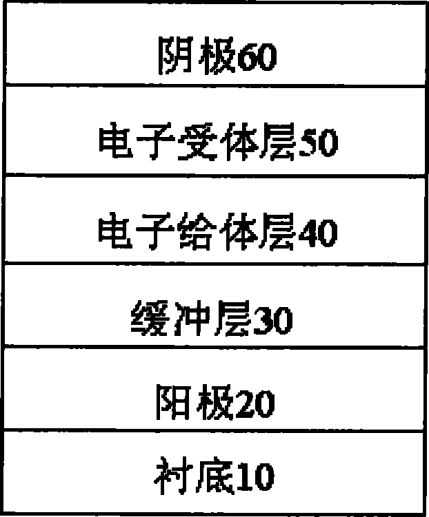
图1是本发明提供的基于氧化物掺杂有机材料的有机太阳能电池结构的示意图;Fig. 1 is a schematic diagram of an organic solar cell structure based on an oxide-doped organic material provided by the present invention;
图2是本发明提供的基于氧化物掺杂有机材料的有机太阳能电池结构的I-V曲线;其中标准器件指ITO/CuPc/C60/Al器件,本发明结构器件为ITO/MoO3∶CuPc/CuPc/C60/Al器件,光源为100mW/cm2的AM1.5的模拟光;Fig. 2 is the IV curve of the organic solar cell structure based on the oxide-doped organic material provided by the present invention; Wherein the standard device refers to the ITO/CuPc/C60/Al device, and the structural device of the present invention is ITO/MoO 3 : CuPc/CuPc/ C60/Al device, the light source is 100mW/cm 2 AM1.5 simulated light;
图3是标准器件与本发明结构器件的效率随时间的变化曲线,测试是在大气环境下进行,器件没有进行封装。Fig. 3 is a time-varying curve of the efficiency of a standard device and a device with a structure of the present invention, the test is carried out in an atmospheric environment, and the device is not packaged.
具体实施方式Detailed ways
为使本发明的目的、技术方案和优点更加清楚明白,以下结合具体实施例,并参照附图,对本发明进一步详细说明。In order to make the object, technical solution and advantages of the present invention clearer, the present invention will be described in further detail below in conjunction with specific embodiments and with reference to the accompanying drawings.
请参阅图1所示,图1是本发明提供的基于氧化物掺杂有机材料的有机太阳能电池结构的示意图,该结构由下至上依次包括:Please refer to Fig. 1, Fig. 1 is a schematic diagram of an organic solar cell structure based on oxide-doped organic materials provided by the present invention, the structure includes from bottom to top:
一透明衬底10,可采用玻璃或者透光性好的柔性聚合物;A transparent substrate 10, glass or flexible polymer with good light transmission can be used;
一阳极20,该阳极20沉积在衬底10上,该阳极可以为以下任一材料:ITO、FTO,或用金或镍等高功函数金属改性过的ITO或FTO;An
一缓冲层30,该缓冲层30沉积在阳极20上,由氧化物掺杂有机材料组成;氧化物可以选择以下任一材料:MoO3、ReO3,WO3;有机材料可选择以下任一材料:CuPc、ZnPc;该缓冲层30中氧化物与有机材料的掺杂时生长速率比例为1∶10至1∶1之间;A buffer layer 30, the buffer layer 30 is deposited on the
一有机电子给体层40,该有机电子给体层40沉积在缓冲层30上,可以选择以下任一材料:CuPc、ZnPc;An organic
一有机电子受体层50,该有机电子受体层50沉积在有机电子给体层40上,可以选择以下任一材料:C60及其衍生物、PTCDA、PTCBI;以及An organic electron acceptor layer 50, the organic electron acceptor layer 50 is deposited on the organic
一阴极60,该阴极60沉积在有机电子受体层50上,可以选择以下任一材料:铝Al、镁银合金。A
本发明提供的是一种可改善有机太阳能电池稳定性的有机太阳能电池结构,所涉及的是一种使用金属氧化物掺杂有机材料作为阳极缓冲层的有机太阳能电池结构,如图1所示,该结构由下至上依次由透明衬底10、阳极20、缓冲层30、电子给体层40、电子受体层50和阴极60构成。The present invention provides an organic solar cell structure that can improve the stability of an organic solar cell, and what it relates to is an organic solar cell structure that uses a metal oxide-doped organic material as an anode buffer layer, as shown in Figure 1. The structure is sequentially composed of a transparent substrate 10 , an
在本发明中,透明衬底10可采用玻璃或者透光性好的柔性聚合物,光线从该衬底10进入器件。In the present invention, the transparent substrate 10 can be made of glass or a flexible polymer with good light transmission, and light enters the device from the substrate 10 .
在本发明中,阳极20沉积在衬底10上,该阳极可以为以下任一材料:ITO、FTO,或用金或镍等高功函数金属改性过的ITO或FTO。In the present invention, the
在本发明中,缓冲层30是指能够平滑、亲润阳极表面、能级匹配以至于能够很好实现空穴传输的有机-无机复合材料,可采用无机材料为低温金属氧化物,可以选择以下任一材料:MoO3、ReO3,WO3,有机材料可以选择CuPc或ZnPc。该缓冲层30中氧化物与有机材料的掺杂时生长速率比例为1∶10至1∶1之间。In the present invention, the buffer layer 30 refers to an organic-inorganic composite material capable of smoothing, wetting the anode surface, and matching energy levels so that holes can be transported well. The inorganic material can be a low-temperature metal oxide, and the following can be selected: Any material: MoO 3 , ReO 3 , WO 3 , organic material can choose CuPc or ZnPc. The growth rate ratio of oxide and organic material in the buffer layer 30 during doping is between 1:10 and 1:1.
在本发明中,有机电子给体层40和有机电子受体层50为光吸收层,激子在两者界面处分离形成自由载流子,给体的LUMO和HOMO能级必须分别高于受体的LUMO和HOMO能级,并且给体和受体的LUMO和HOMO能级之差必须大于0.4eV。此外,有机电子给体层40应与掺杂的缓冲层的HOMO能级匹配,可采用CuPc或ZnPc;有机电子受体层50可选择以下任一材料:C60及其衍生物、PTCDA、PTCBI。In the present invention, the organic
在本发明中,阴极60可采用铝或镁银合金。In the present invention, the
本发明中,除了阳极和阴极外,其余各层可以采用真空蒸发、旋涂、打印等各种沉积有机膜的方法来制备。缓冲层(如MoO3掺杂CuPc)的实现可采用共蒸发技术或将氧化物和有机材料共溶于同一种溶剂然后旋涂或打印的方法来实现。In the present invention, except for the anode and the cathode, the other layers can be prepared by various methods of depositing organic films such as vacuum evaporation, spin coating, and printing. The buffer layer (such as MoO 3 doped CuPc) can be realized by co-evaporation technology or co-dissolving oxide and organic materials in the same solvent and then spin-coating or printing.
通过引入掺杂的缓冲层,将改善有机给体层与阳极之间的界面形貌,同时降低ITO阳极中的In向有机材料的渗入,可以提高有机太阳能电池的稳定性。By introducing a doped buffer layer, the interface morphology between the organic donor layer and the anode will be improved, and at the same time, the infiltration of In in the ITO anode into the organic material will be reduced, which can improve the stability of the organic solar cell.
本发明提出的有机太阳能电池结构,电池的填充因子增大,能量转换效率略有提高。表1为标准器件与本发明器件的性能比较。器件的稳定性相比标准器件结构得到改善(见图3)。In the structure of the organic solar cell proposed by the invention, the filling factor of the cell is increased, and the energy conversion efficiency is slightly improved. Table 1 is the performance comparison between the standard device and the device of the present invention. The stability of the device is improved compared to the standard device structure (see Figure 3).

表1Table 1
下面结合实施例对本发明进行具体描述,但是本发明并不仅仅局限于所列举的实施例。The present invention is specifically described below in conjunction with the examples, but the present invention is not limited to the examples listed.
在清洗干净的ITO玻璃衬底上生长太阳能电池,ITO厚度约150nm,方块电阻约20Ω/□。采用有机分子束沉积设备(OMBD)生长有机薄膜和阴极,生长时真空约为4×10-7Torr。有机薄膜生长速率约

器件结构为:标准器件ITO/CuPc 40nm/C6050nm/Al,本发明结构器件ITO/MoO3∶CuPc(1∶10)10nm/CuPc 30nm/C6050nm/Al。The device structure is: standard device ITO/CuPc 40nm/C6050nm/Al, and the inventive structure device ITO/MoO 3 : CuPc (1:10) 10nm/CuPc 30nm/C6050nm/Al.
器件在光照情况下的I-V曲线如图2所示,器件效率随时间的变化如图3所示。在空气中放置30分钟后,标准器件的效率降低到最初的63%,而本发明器件的效率为最初的80%,器件的稳定性得到改善。The I-V curve of the device under light conditions is shown in Figure 2, and the change of device efficiency with time is shown in Figure 3. After being placed in the air for 30 minutes, the efficiency of the standard device is reduced to 63% of the initial value, while the efficiency of the device of the present invention is 80% of the initial value, and the stability of the device is improved.
本文中有关缩写名称的含义如下:The meanings of the abbreviated names in this article are as follows:
ITO:铟锡氧化物ITO: indium tin oxide
MoO3:氧化钼MoO 3 : molybdenum oxide
ReO3:氧化铼ReO 3 : rhenium oxide
WO3:氧化钨WO 3 : Tungsten Oxide
CuPc:酞菁铜(Copper phthalocyanine)CuPc: copper phthalocyanine (Copper phthalocyanine)
ZnPc:酞菁锌(Zinc phthalocyanine)ZnPc: Zinc phthalocyanine
C60:富勒烯(fulleren)C60: fullerene (fulleren)
PTCDA:苝四甲酸二酐(3,4,9,10-perylene tetracarboxylic)PTCDA: perylene tetracarboxylic dianhydride (3,4,9,10-perylene tetracarboxylic)
PTCBI:二苯并咪唑代-3,4,9,10-四羧基苝(3,4,9,10-perylenetetracarboxylic bis-benzimidazole)PTCBI: Dibenzimidazole-3,4,9,10-tetracarboxyperylene (3,4,9,10-perylenetetracarboxylic bis-benzimidazole)
HOMO:最高分子占有轨道HOMO: Highest Molecular Occupied Orbital
LUMO:最低分子未占有轨道LUMO: lowest molecular unoccupied orbital
以上所述的具体实施例,对本发明的目的、技术方案和有益效果进行了进一步详细说明,所应理解的是,以上所述仅为本发明的具体实施例而已,并不用于限制本发明,凡在本发明的精神和原则之内,所做的任何修改、等同替换、改进等,均应包含在本发明的保护范围之内。The specific embodiments described above have further described the purpose, technical solutions and beneficial effects of the present invention in detail. It should be understood that the above descriptions are only specific embodiments of the present invention and are not intended to limit the present invention. Any modifications, equivalent replacements, improvements, etc. made within the spirit and principles of the present invention shall be included within the protection scope of the present invention.
Claims (6)
Priority Applications (1)
| Application Number | Priority Date | Filing Date | Title |
|---|---|---|---|
| CN 201010504161 CN102024906B (en) | 2010-09-30 | 2010-09-30 | An organic solar cell structure based on oxide-doped organic materials |
Applications Claiming Priority (1)
| Application Number | Priority Date | Filing Date | Title |
|---|---|---|---|
| CN 201010504161 CN102024906B (en) | 2010-09-30 | 2010-09-30 | An organic solar cell structure based on oxide-doped organic materials |
Publications (2)
| Publication Number | Publication Date |
|---|---|
| CN102024906A CN102024906A (en) | 2011-04-20 |
| CN102024906B true CN102024906B (en) | 2012-09-19 |
Family
ID=43865968
Family Applications (1)
| Application Number | Title | Priority Date | Filing Date |
|---|---|---|---|
| CN 201010504161 Expired - Fee Related CN102024906B (en) | 2010-09-30 | 2010-09-30 | An organic solar cell structure based on oxide-doped organic materials |
Country Status (1)
| Country | Link |
|---|---|
| CN (1) | CN102024906B (en) |
Families Citing this family (9)
| Publication number | Priority date | Publication date | Assignee | Title |
|---|---|---|---|---|
| CN102569654B (en) * | 2012-01-13 | 2015-05-13 | 暨南大学 | Organic solar cell doped with phosphorescent dye |
| CN102623641A (en) * | 2012-03-27 | 2012-08-01 | 华北电力大学 | Polymer solar anode modifying battery and preparation method thereof |
| CN102610759A (en) * | 2012-03-30 | 2012-07-25 | 中国科学院长春应用化学研究所 | Conjugated thin polymer film solar cell and method for producing same |
| CN103422056A (en) * | 2012-05-14 | 2013-12-04 | 海洋王照明科技股份有限公司 | Conductive thin film, and preparation method and application thereof |
| CN103824946A (en) * | 2012-11-19 | 2014-05-28 | 海洋王照明科技股份有限公司 | Polymer solar cell and preparation method thereof |
| CN104051660A (en) * | 2013-03-12 | 2014-09-17 | 海洋王照明科技股份有限公司 | Composite anode and manufacturing method thereof, and organic electroluminescent device and manufacturing method thereof |
| CN105493304B (en) * | 2013-08-06 | 2020-01-31 | 新南创新私人有限公司 | High efficiency stacked solar cells |
| CN114094015A (en) * | 2021-11-29 | 2022-02-25 | 长春工业大学 | A preparation method of a vertical diode-based gas sensor based on a flexible substrate |
| CN114921804B (en) * | 2022-04-26 | 2023-06-20 | 华南理工大学 | A photoelectrode material based on InN/organic heterostructure and its preparation method and application |
Citations (2)
| Publication number | Priority date | Publication date | Assignee | Title |
|---|---|---|---|---|
| CN1617355A (en) * | 2004-12-09 | 2005-05-18 | 复旦大学 | Novel organic solar energy cell structure and its preparing method |
| CN1719956A (en) * | 2004-07-08 | 2006-01-11 | 城户淳二 | Organic devices, organic electroluminescent devices and organic solar cells |
-
2010
- 2010-09-30 CN CN 201010504161 patent/CN102024906B/en not_active Expired - Fee Related
Patent Citations (2)
| Publication number | Priority date | Publication date | Assignee | Title |
|---|---|---|---|---|
| CN1719956A (en) * | 2004-07-08 | 2006-01-11 | 城户淳二 | Organic devices, organic electroluminescent devices and organic solar cells |
| CN1617355A (en) * | 2004-12-09 | 2005-05-18 | 复旦大学 | Novel organic solar energy cell structure and its preparing method |
Also Published As
| Publication number | Publication date |
|---|---|
| CN102024906A (en) | 2011-04-20 |
Similar Documents
| Publication | Publication Date | Title |
|---|---|---|
| CN102024906B (en) | An organic solar cell structure based on oxide-doped organic materials | |
| Yan et al. | Hole‐transporting materials in inverted planar perovskite solar cells | |
| Qian et al. | Hybrid polymer-CdSe solar cells with a ZnO nanoparticle buffer layer for improved efficiency and lifetime | |
| Sun et al. | Solution-processed copper iodide as an inexpensive and effective anode buffer layer for polymer solar cells | |
| Wang et al. | Degradation mechanism of organic solar cells with aluminum cathode | |
| CN111129315A (en) | A kind of inverted planar heterojunction hybrid perovskite solar cell and preparation method | |
| JP5682571B2 (en) | Organic photoelectric conversion element | |
| Pan et al. | All-solution processed double-decked PEDOT: PSS/V2O5 nanowires as buffer layer of high performance polymer photovoltaic cells | |
| CN108232016B (en) | Perovskite solar cells based on cellulose modified hole transport layer | |
| CN102891259B (en) | Donor organic solar batteries being separated vertical with acceptor and preparation method thereof | |
| CN108864414A (en) | Embellishing cathode interface material, solar battery and preparation method thereof and application | |
| CN110854273A (en) | Organic bulk heterojunction-doped perovskite solar cell and preparation method thereof | |
| CN108598269A (en) | Thick-film organic solar cell based on non-fullerene receptor and preparation method | |
| CN100375311C (en) | A novel organic solar cell structure and preparation method thereof | |
| CN103296209A (en) | Solar cell combining heterostructure plasmons and bulk heterojunctions | |
| CN102386336B (en) | Inverted-structure polymer body heterojunction solar cell and manufacturing method thereof | |
| JP5862189B2 (en) | Organic photoelectric conversion device and solar cell using the same | |
| CN107611266A (en) | A kind of flexible organic photodetector and preparation method thereof | |
| CN102064281A (en) | Organic photovoltaic battery with cesium acetate as cathode modification layer and preparation method thereof | |
| CN106025078B (en) | A kind of planar heterojunction perovskite photovoltaic cell and preparation method thereof | |
| CN103208588B (en) | A kind of inverted structure organic/polymer solar battery | |
| Chen et al. | High performance thermal-treatment-free tandem polymer solar cells with high fill factors | |
| CN112885967A (en) | Double-layer organic solar cell based on delayed fluorescent material and preparation method | |
| CN105185911B (en) | A kind of polymer solar battery based on solvent doping and preparation method thereof | |
| CN101640133B (en) | Polymer/inorganic nano-crystal hybrid solar cell and manufacture method thereof |
Legal Events
| Date | Code | Title | Description |
|---|---|---|---|
| C06 | Publication | ||
| PB01 | Publication | ||
| C10 | Entry into substantive examination | ||
| SE01 | Entry into force of request for substantive examination | ||
| C14 | Grant of patent or utility model | ||
| GR01 | Patent grant | ||
| CF01 | Termination of patent right due to non-payment of annual fee |
Granted publication date: 20120919 Termination date: 20150930 |
|
| EXPY | Termination of patent right or utility model |