CN101966911A - Conveying roller way - Google Patents
Conveying roller way Download PDFInfo
- Publication number
- CN101966911A CN101966911A CN 201010240596 CN201010240596A CN101966911A CN 101966911 A CN101966911 A CN 101966911A CN 201010240596 CN201010240596 CN 201010240596 CN 201010240596 A CN201010240596 A CN 201010240596A CN 101966911 A CN101966911 A CN 101966911A
- Authority
- CN
- China
- Prior art keywords
- rollers
- unpowered
- travel
- ing rest
- powered
- Prior art date
- Legal status (The legal status is an assumption and is not a legal conclusion. Google has not performed a legal analysis and makes no representation as to the accuracy of the status listed.)
- Pending
Links
Images


Landscapes
- Rollers For Roller Conveyors For Transfer (AREA)
Abstract
The invention relates to a conveying roller way. The conveying roller way is provided with a fixed bracket; a plurality of rows of unpowered rollers are arranged on the fixed bracket; a movable bracket capable of ascending and descending is arranged on the inner side of the fixed bracket through two pairs of lifting cylinders; a motor and a plurality of rows of powered rollers are arranged on the movable bracket; a chain wheel is arranged on the powered rollers; the motor drives the powered rollers to rotate through a chain; a long hole is formed between the adjacent powered rollers on the movable bracket; a rotating shaft of the unpowered rollers passes through the long hole of the movable bracket and is fixed on the fixed bracket through a bolt; and the unpowered rollers can freely rotate around the rotating shaft. The powered rollers can move up and down between the two adjacent unpowered rollers to be higher than or lower than the unpowered rollers. The conveying roller way has the function of a powered track, can be driven by the powered roller to move freely, also can be used as an unpowered roller way, and is suitable for transferring and conveying among procedures during processing mechanical parts such as a crankshaft and the like.
Description
Technical field
The present invention relates to a kind of Work transfer device, specifically a kind of rollgang.
Background technology
We know, in the manufacturing of mechanical parts such as bent axle, pass through a lot of manufacturing procedures.It generally is the turnover conveying of carrying out inter process by the roller load transfer device.Roller load transfer device commonly used is divided into unpowered rollgang and two kinds of forms of power rollgang.Article move on unpowered roller-way and need apply external force, and article are subjected to the external force effect can static at any time or free motion back and forth.And on the power roller-way, article are driven by roller ground, can be automatically towards a direction motion.So can't satisfying article, two kinds of above-mentioned roller-ways on roller-way, both can be subjected to roller to drive automatic moving, again can free-moving back and forth requirement.
Summary of the invention
Technical matters to be solved by this invention is to overcome above-mentioned the deficiencies in the prior art, provides a kind of rational in infrastructure, easy to assembly, makes simply, has both had the function of power rail, can work as the novel rollgang that unpowered roller-way uses again.
The technical scheme that the present invention solves the problems of the technologies described above employing is: a kind of rollgang, it is provided with fixed support, the unpowered roller of plurality of rows is installed on the fixed support, it is characterized in that: but the travel(l)ing rest that oscilaltion is installed by two pairs of lift cylinders surveyed in the described fixed support, motor and plurality of rows live roll are installed on the travel(l)ing rest, sprocket wheel is installed on the live roll, motor rotates by the chain drive live roll, live roll centre adjacent on the travel(l)ing rest is provided with slotted hole, the slotted hole of travel(l)ing rest is passed in the rotating shaft of unpowered roller, by being bolted on the fixed support, unpowered roller can freely rotate around the rotating shaft of himself.
The said lift cylinder of the present invention is fixed on the fixed support by the cylinder support, and the cylinder rod of lift cylinder is connected and fixed by contiguous block and travel(l)ing rest.
The present invention adopts said mechanism, and lift cylinder can drive the travel(l)ing rest up-and-down movement that live roll and drive motor are installed, and makes live roll slightly be higher or lower than unpowered roller.Against existing technologies, the present invention is rational in infrastructure, and is easy to assembly, makes simply, and when live roll slightly exceeded unpowered roller, live roll contact with being transferred article, and driving is transferred article and moves, and roller-way has the function of power roller-way; When live roll was lower than unpowered roller, unpowered roller contacted with being transferred article, and this moment, roller-way had the function of unpowered roller-way again.The present invention had both had the function of power rail, driven automatically by live roll and move, and can work as unpowered roller-way again and use, and can come and go free motion at unpowered roller-way, was suitable for inter process turnover conveying in the course of processing of mechanical parts such as bent axle.
Description of drawings
The invention will be further described below in conjunction with accompanying drawing.
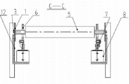
Fig. 1 is a structural representation of the present invention.
Fig. 2 is A-A cutaway view of Fig. 1.
Fig. 3 is B-B cutaway view of Fig. 2.
Fig. 4 is C-C cutaway view of Fig. 2.
Among the figure: 1. fixed support, 2. sprocket wheel, 3. bolt, 4. live roll, 5. unpowered roller, 6. travel(l)ing rest, 7. contiguous block, 8. lift cylinder, 9. driving chain, 10. motor, 11. motor sprockets, 12. cylinder supports.
The specific embodiment
From Fig. 1, Fig. 2, Fig. 3, Fig. 4 as can be seen: a kind of rollgang, it is provided with fixed support 1, the unpowered roller 5 of plurality of rows is installed on the fixed support 1, and unpowered roller 5 is to be fixed on the fixed support 1 by bolt 3, and unpowered roller 5 can freely rotate around the rotating shaft of himself.Unpowered roller is the roller that can rotate freely that does not have driving action to articles conveyed.
But survey the travel(l)ing rest 6 that oscilaltion is installed by two pairs of lift cylinders 8 in the described fixed support 1.Said lift cylinder 8 is fixed on the fixed support 1 by cylinder support 12, and the cylinder rod of lift cylinder 8 is connected and fixed by contiguous block 7 and travel(l)ing rest 6.Travel(l)ing rest 6 is tabular, and plurality of rows live roll 4 and drive motor 10 are installed above; Sprocket wheel 2 is installed on the live roll 4, motor sprocket 11 is installed on the motor 10, motor sprocket 11 and sprocket wheel 2 link together by driving chain 9, and drive live roll 4 rotations by motor 10.Live roll 4 is to being transferred article the roller of driving action to be arranged.
It can also be seen that by Fig. 1, Fig. 2, Fig. 4, live roll 4 centres adjacent on the described travel(l)ing rest 6 are provided with slotted holes, the slotted hole of travel(l)ing rest 6 is passed in the rotating shaft of unpowered roller 5, is fixed on the fixed support 1 by bolt 3, and unpowered roller 5 can freely rotate around the rotating shaft of himself.Because lift cylinder 8 is installed on the fixed support 1 by cylinder support 12, the cylinder rod of lift cylinder 8 connects together by contiguous block 7 and travel(l)ing rest 6 again, so during lift cylinder 8 actions, drive travel(l)ing rest 6 up-and-down movements, be installed in the live roll 4 on the travel(l)ing rest 6 like this, can be between two adjacent unpowered rollers 5 up-and-down movement, make it be higher or lower than unpowered roller.And can when up-and-down movement, not run into unpowered roller.When live roll 4 slightly exceeded unpowered roller 5, roller-way had the function of power roller-way; When live roll 4 was lower than unpowered roller 5, roller-way had the function of unpowered roller-way again.
Claims (2)
1. rollgang, it is provided with fixed support, the unpowered roller of plurality of rows is installed on the fixed support, it is characterized in that: but the travel(l)ing rest that oscilaltion is installed by two pairs of lift cylinders surveyed in the described fixed support, motor and plurality of rows live roll are installed on the travel(l)ing rest, sprocket wheel is installed on the live roll, motor rotates by the chain drive live roll, live roll centre adjacent on the travel(l)ing rest is provided with slotted hole, the slotted hole of travel(l)ing rest is passed in the rotating shaft of unpowered roller, by being bolted on the fixed support, unpowered roller can freely rotate around the rotating shaft of himself.
2. according to the described rollgang of claim 1, it is characterized in that: said lift cylinder is fixed on the fixed support by the cylinder support, and the cylinder rod of lift cylinder is connected and fixed by contiguous block and travel(l)ing rest.
Priority Applications (1)
| Application Number | Priority Date | Filing Date | Title |
|---|---|---|---|
| CN 201010240596 CN101966911A (en) | 2010-07-30 | 2010-07-30 | Conveying roller way |
Applications Claiming Priority (1)
| Application Number | Priority Date | Filing Date | Title |
|---|---|---|---|
| CN 201010240596 CN101966911A (en) | 2010-07-30 | 2010-07-30 | Conveying roller way |
Publications (1)
| Publication Number | Publication Date |
|---|---|
| CN101966911A true CN101966911A (en) | 2011-02-09 |
Family
ID=43546154
Family Applications (1)
| Application Number | Title | Priority Date | Filing Date |
|---|---|---|---|
| CN 201010240596 Pending CN101966911A (en) | 2010-07-30 | 2010-07-30 | Conveying roller way |
Country Status (1)
| Country | Link |
|---|---|
| CN (1) | CN101966911A (en) |
Cited By (11)
| Publication number | Priority date | Publication date | Assignee | Title |
|---|---|---|---|---|
| CN102419074A (en) * | 2011-12-27 | 2012-04-18 | 李宝金 | Lignite drier |
| CN103086115A (en) * | 2011-11-07 | 2013-05-08 | 四川汇利实业有限公司 | Power transmission device with sensor |
| CN103086116A (en) * | 2011-11-07 | 2013-05-08 | 四川汇利实业有限公司 | Power transmission device capable of effectively improving stability |
| CN103418706A (en) * | 2013-08-29 | 2013-12-04 | 济钢集团有限公司 | Rod material cold shearing double-roller-diameter steel turning device |
| CN105290868A (en) * | 2015-11-06 | 2016-02-03 | 遵义智鹏高新铝材有限公司 | Aluminum bar propelling device |
| CN106276038A (en) * | 2016-08-18 | 2017-01-04 | 南通通机股份有限公司 | A kind of fully automatic winding transfer machine |
| CN108438723A (en) * | 2018-01-30 | 2018-08-24 | 东莞市天合机电开发有限公司 | A kind of height adjustable automobiles mold conveying mechanism |
| CN110796788A (en) * | 2018-08-03 | 2020-02-14 | 威海新北洋数码科技有限公司 | Goods delivery device and vending machine |
| CN110921191A (en) * | 2019-10-25 | 2020-03-27 | 浙江省建工集团有限责任公司 | Steel plate lifting and conveying mechanism |
| CN110950000A (en) * | 2019-12-10 | 2020-04-03 | 昆明理工大学 | Roller conveyor |
| CN113371416A (en) * | 2021-06-25 | 2021-09-10 | 中核二七二铀业有限责任公司 | Application method of automated uranium conversion material conveying link |
Citations (5)
| Publication number | Priority date | Publication date | Assignee | Title |
|---|---|---|---|---|
| JPS56141220A (en) * | 1980-03-31 | 1981-11-04 | Toshiba Corp | Conveyer device |
| JPS58135006A (en) * | 1982-02-04 | 1983-08-11 | Yasunari Hirata | Driving gear of intermittently driven conveyer |
| JPH1087040A (en) * | 1996-09-20 | 1998-04-07 | Okamura Corp | Roller conveyer device |
| WO2009103277A2 (en) * | 2008-02-21 | 2009-08-27 | Grenzebach Maschinenbau Gmbh | Method and device for conveying and rotating impact-sensitive panels in ultra clean rooms |
| CN201737421U (en) * | 2010-07-30 | 2011-02-09 | 天润曲轴股份有限公司 | Conveying roller |
-
2010
- 2010-07-30 CN CN 201010240596 patent/CN101966911A/en active Pending
Patent Citations (5)
| Publication number | Priority date | Publication date | Assignee | Title |
|---|---|---|---|---|
| JPS56141220A (en) * | 1980-03-31 | 1981-11-04 | Toshiba Corp | Conveyer device |
| JPS58135006A (en) * | 1982-02-04 | 1983-08-11 | Yasunari Hirata | Driving gear of intermittently driven conveyer |
| JPH1087040A (en) * | 1996-09-20 | 1998-04-07 | Okamura Corp | Roller conveyer device |
| WO2009103277A2 (en) * | 2008-02-21 | 2009-08-27 | Grenzebach Maschinenbau Gmbh | Method and device for conveying and rotating impact-sensitive panels in ultra clean rooms |
| CN201737421U (en) * | 2010-07-30 | 2011-02-09 | 天润曲轴股份有限公司 | Conveying roller |
Cited By (12)
| Publication number | Priority date | Publication date | Assignee | Title |
|---|---|---|---|---|
| CN103086115A (en) * | 2011-11-07 | 2013-05-08 | 四川汇利实业有限公司 | Power transmission device with sensor |
| CN103086116A (en) * | 2011-11-07 | 2013-05-08 | 四川汇利实业有限公司 | Power transmission device capable of effectively improving stability |
| CN102419074A (en) * | 2011-12-27 | 2012-04-18 | 李宝金 | Lignite drier |
| CN103418706A (en) * | 2013-08-29 | 2013-12-04 | 济钢集团有限公司 | Rod material cold shearing double-roller-diameter steel turning device |
| CN105290868A (en) * | 2015-11-06 | 2016-02-03 | 遵义智鹏高新铝材有限公司 | Aluminum bar propelling device |
| CN106276038A (en) * | 2016-08-18 | 2017-01-04 | 南通通机股份有限公司 | A kind of fully automatic winding transfer machine |
| CN108438723A (en) * | 2018-01-30 | 2018-08-24 | 东莞市天合机电开发有限公司 | A kind of height adjustable automobiles mold conveying mechanism |
| CN110796788A (en) * | 2018-08-03 | 2020-02-14 | 威海新北洋数码科技有限公司 | Goods delivery device and vending machine |
| CN110921191A (en) * | 2019-10-25 | 2020-03-27 | 浙江省建工集团有限责任公司 | Steel plate lifting and conveying mechanism |
| CN110950000A (en) * | 2019-12-10 | 2020-04-03 | 昆明理工大学 | Roller conveyor |
| CN113371416A (en) * | 2021-06-25 | 2021-09-10 | 中核二七二铀业有限责任公司 | Application method of automated uranium conversion material conveying link |
| CN113371416B (en) * | 2021-06-25 | 2022-10-04 | 中核二七二铀业有限责任公司 | Application method of automated uranium conversion material conveying link |
Similar Documents
| Publication | Publication Date | Title |
|---|---|---|
| CN101966911A (en) | Conveying roller way | |
| CN204280504U (en) | A kind of chain mat machine | |
| CN101391695A (en) | Stacking roller conveyor | |
| CN103332479A (en) | Rotating platform for tire conveying line | |
| CN201737421U (en) | Conveying roller | |
| CN201545509U (en) | Automatic hanging-changing system | |
| CN202098805U (en) | Transmission chain of sorting machine | |
| CN204384468U (en) | A kind of novel setting machine kinematic mechanism | |
| CN205802391U (en) | A kind of handling and conveying elevator | |
| CN210285549U (en) | Chain panel buffer memory frame | |
| CN105059901A (en) | Right-angle distribution machine driven to conduct distribution in servo mode | |
| CN202156713U (en) | Middle baffle device for conveying machine | |
| CN201686280U (en) | Bearing roller conveyor chain | |
| CN204150665U (en) | Bench board parallel motion lifter plate chain feedway | |
| CN2848815Y (en) | Belt type lifting mechanism | |
| CN201729475U (en) | Hemp motor conveyer | |
| CN204896638U (en) | Multilayer conveyer | |
| CN205589914U (en) | Wheeled mould platform circulation system | |
| CN201002877Y (en) | Mining plate-belt feeder | |
| CN203976303U (en) | The bay-lift table top of energy translation | |
| CN204038557U (en) | Three jacking transferring machines | |
| CN202186684U (en) | Material box transporting and positioning device | |
| CN201020796Y (en) | Loading machine set for splint direction change | |
| CN205837950U (en) | Conveying assembly | |
| CN211619034U (en) | Sprocket type transmission structure of high-speed linear conveyor |
Legal Events
| Date | Code | Title | Description |
|---|---|---|---|
| C06 | Publication | ||
| PB01 | Publication | ||
| C10 | Entry into substantive examination | ||
| SE01 | Entry into force of request for substantive examination | ||
| C02 | Deemed withdrawal of patent application after publication (patent law 2001) | ||
| WD01 | Invention patent application deemed withdrawn after publication |
Application publication date: 20110209 |