CN101900956A - Remove the method for material from base material - Google Patents
Remove the method for material from base material Download PDFInfo
- Publication number
- CN101900956A CN101900956A CN2010102133298A CN201010213329A CN101900956A CN 101900956 A CN101900956 A CN 101900956A CN 2010102133298 A CN2010102133298 A CN 2010102133298A CN 201010213329 A CN201010213329 A CN 201010213329A CN 101900956 A CN101900956 A CN 101900956A
- Authority
- CN
- China
- Prior art keywords
- temperature
- sulphuric acid
- water
- acid composition
- sulfuric acid
- Prior art date
- Legal status (The legal status is an assumption and is not a legal conclusion. Google has not performed a legal analysis and makes no representation as to the accuracy of the status listed.)
- Pending
Links
Images


Classifications
-
- B—PERFORMING OPERATIONS; TRANSPORTING
- B05—SPRAYING OR ATOMISING IN GENERAL; APPLYING FLUENT MATERIALS TO SURFACES, IN GENERAL
- B05B—SPRAYING APPARATUS; ATOMISING APPARATUS; NOZZLES
- B05B1/00—Nozzles, spray heads or other outlets, with or without auxiliary devices such as valves, heating means
-
- B—PERFORMING OPERATIONS; TRANSPORTING
- B05—SPRAYING OR ATOMISING IN GENERAL; APPLYING FLUENT MATERIALS TO SURFACES, IN GENERAL
- B05B—SPRAYING APPARATUS; ATOMISING APPARATUS; NOZZLES
- B05B7/00—Spraying apparatus for discharge of liquids or other fluent materials from two or more sources, e.g. of liquid and air, of powder and gas
- B05B7/02—Spray pistols; Apparatus for discharge
- B05B7/12—Spray pistols; Apparatus for discharge designed to control volume of flow, e.g. with adjustable passages
- B05B7/1209—Spray pistols; Apparatus for discharge designed to control volume of flow, e.g. with adjustable passages the controlling means for each liquid or other fluent material being manual and interdependent
-
- B—PERFORMING OPERATIONS; TRANSPORTING
- B08—CLEANING
- B08B—CLEANING IN GENERAL; PREVENTION OF FOULING IN GENERAL
- B08B3/00—Cleaning by methods involving the use or presence of liquid or steam
- B08B3/04—Cleaning involving contact with liquid
- B08B3/08—Cleaning involving contact with liquid the liquid having chemical or dissolving effect
-
- B—PERFORMING OPERATIONS; TRANSPORTING
- B08—CLEANING
- B08B—CLEANING IN GENERAL; PREVENTION OF FOULING IN GENERAL
- B08B3/00—Cleaning by methods involving the use or presence of liquid or steam
- B08B3/04—Cleaning involving contact with liquid
- B08B3/10—Cleaning involving contact with liquid with additional treatment of the liquid or of the object being cleaned, e.g. by heat, by electricity or by vibration
-
- B—PERFORMING OPERATIONS; TRANSPORTING
- B08—CLEANING
- B08B—CLEANING IN GENERAL; PREVENTION OF FOULING IN GENERAL
- B08B7/00—Cleaning by methods not provided for in a single other subclass or a single group in this subclass
-
- G—PHYSICS
- G03—PHOTOGRAPHY; CINEMATOGRAPHY; ANALOGOUS TECHNIQUES USING WAVES OTHER THAN OPTICAL WAVES; ELECTROGRAPHY; HOLOGRAPHY
- G03F—PHOTOMECHANICAL PRODUCTION OF TEXTURED OR PATTERNED SURFACES, e.g. FOR PRINTING, FOR PROCESSING OF SEMICONDUCTOR DEVICES; MATERIALS THEREFOR; ORIGINALS THEREFOR; APPARATUS SPECIALLY ADAPTED THEREFOR
- G03F7/00—Photomechanical, e.g. photolithographic, production of textured or patterned surfaces, e.g. printing surfaces; Materials therefor, e.g. comprising photoresists; Apparatus specially adapted therefor
- G03F7/26—Processing photosensitive materials; Apparatus therefor
- G03F7/42—Stripping or agents therefor
- G03F7/422—Stripping or agents therefor using liquids only
- G03F7/423—Stripping or agents therefor using liquids only containing mineral acids or salts thereof, containing mineral oxidizing substances, e.g. peroxy compounds
-
- H—ELECTRICITY
- H01—ELECTRIC ELEMENTS
- H01L—SEMICONDUCTOR DEVICES NOT COVERED BY CLASS H10
- H01L21/00—Processes or apparatus adapted for the manufacture or treatment of semiconductor or solid state devices or of parts thereof
- H01L21/02—Manufacture or treatment of semiconductor devices or of parts thereof
- H01L21/02041—Cleaning
- H01L21/02057—Cleaning during device manufacture
- H01L21/0206—Cleaning during device manufacture during, before or after processing of insulating layers
- H01L21/02063—Cleaning during device manufacture during, before or after processing of insulating layers the processing being the formation of vias or contact holes
-
- H—ELECTRICITY
- H01—ELECTRIC ELEMENTS
- H01L—SEMICONDUCTOR DEVICES NOT COVERED BY CLASS H10
- H01L21/00—Processes or apparatus adapted for the manufacture or treatment of semiconductor or solid state devices or of parts thereof
- H01L21/02—Manufacture or treatment of semiconductor devices or of parts thereof
- H01L21/02041—Cleaning
- H01L21/02057—Cleaning during device manufacture
- H01L21/02068—Cleaning during device manufacture during, before or after processing of conductive layers, e.g. polysilicon or amorphous silicon layers
- H01L21/02071—Cleaning during device manufacture during, before or after processing of conductive layers, e.g. polysilicon or amorphous silicon layers the processing being a delineation, e.g. RIE, of conductive layers
-
- H—ELECTRICITY
- H01—ELECTRIC ELEMENTS
- H01L—SEMICONDUCTOR DEVICES NOT COVERED BY CLASS H10
- H01L21/00—Processes or apparatus adapted for the manufacture or treatment of semiconductor or solid state devices or of parts thereof
- H01L21/02—Manufacture or treatment of semiconductor devices or of parts thereof
- H01L21/04—Manufacture or treatment of semiconductor devices or of parts thereof the devices having at least one potential-jump barrier or surface barrier, e.g. PN junction, depletion layer or carrier concentration layer
- H01L21/18—Manufacture or treatment of semiconductor devices or of parts thereof the devices having at least one potential-jump barrier or surface barrier, e.g. PN junction, depletion layer or carrier concentration layer the devices having semiconductor bodies comprising elements of Group IV of the Periodic System or AIIIBV compounds with or without impurities, e.g. doping materials
- H01L21/30—Treatment of semiconductor bodies using processes or apparatus not provided for in groups H01L21/20 - H01L21/26
- H01L21/302—Treatment of semiconductor bodies using processes or apparatus not provided for in groups H01L21/20 - H01L21/26 to change their surface-physical characteristics or shape, e.g. etching, polishing, cutting
- H01L21/306—Chemical or electrical treatment, e.g. electrolytic etching
- H01L21/30604—Chemical etching
-
- H—ELECTRICITY
- H01—ELECTRIC ELEMENTS
- H01L—SEMICONDUCTOR DEVICES NOT COVERED BY CLASS H10
- H01L21/00—Processes or apparatus adapted for the manufacture or treatment of semiconductor or solid state devices or of parts thereof
- H01L21/02—Manufacture or treatment of semiconductor devices or of parts thereof
- H01L21/04—Manufacture or treatment of semiconductor devices or of parts thereof the devices having at least one potential-jump barrier or surface barrier, e.g. PN junction, depletion layer or carrier concentration layer
- H01L21/18—Manufacture or treatment of semiconductor devices or of parts thereof the devices having at least one potential-jump barrier or surface barrier, e.g. PN junction, depletion layer or carrier concentration layer the devices having semiconductor bodies comprising elements of Group IV of the Periodic System or AIIIBV compounds with or without impurities, e.g. doping materials
- H01L21/30—Treatment of semiconductor bodies using processes or apparatus not provided for in groups H01L21/20 - H01L21/26
- H01L21/31—Treatment of semiconductor bodies using processes or apparatus not provided for in groups H01L21/20 - H01L21/26 to form insulating layers thereon, e.g. for masking or by using photolithographic techniques; After treatment of these layers; Selection of materials for these layers
- H01L21/3105—After-treatment
- H01L21/311—Etching the insulating layers by chemical or physical means
- H01L21/31105—Etching inorganic layers
-
- H—ELECTRICITY
- H01—ELECTRIC ELEMENTS
- H01L—SEMICONDUCTOR DEVICES NOT COVERED BY CLASS H10
- H01L21/00—Processes or apparatus adapted for the manufacture or treatment of semiconductor or solid state devices or of parts thereof
- H01L21/02—Manufacture or treatment of semiconductor devices or of parts thereof
- H01L21/04—Manufacture or treatment of semiconductor devices or of parts thereof the devices having at least one potential-jump barrier or surface barrier, e.g. PN junction, depletion layer or carrier concentration layer
- H01L21/18—Manufacture or treatment of semiconductor devices or of parts thereof the devices having at least one potential-jump barrier or surface barrier, e.g. PN junction, depletion layer or carrier concentration layer the devices having semiconductor bodies comprising elements of Group IV of the Periodic System or AIIIBV compounds with or without impurities, e.g. doping materials
- H01L21/30—Treatment of semiconductor bodies using processes or apparatus not provided for in groups H01L21/20 - H01L21/26
- H01L21/31—Treatment of semiconductor bodies using processes or apparatus not provided for in groups H01L21/20 - H01L21/26 to form insulating layers thereon, e.g. for masking or by using photolithographic techniques; After treatment of these layers; Selection of materials for these layers
- H01L21/3105—After-treatment
- H01L21/311—Etching the insulating layers by chemical or physical means
- H01L21/31127—Etching organic layers
- H01L21/31133—Etching organic layers by chemical means
-
- H—ELECTRICITY
- H01—ELECTRIC ELEMENTS
- H01L—SEMICONDUCTOR DEVICES NOT COVERED BY CLASS H10
- H01L21/00—Processes or apparatus adapted for the manufacture or treatment of semiconductor or solid state devices or of parts thereof
- H01L21/67—Apparatus specially adapted for handling semiconductor or electric solid state devices during manufacture or treatment thereof; Apparatus specially adapted for handling wafers during manufacture or treatment of semiconductor or electric solid state devices or components ; Apparatus not specifically provided for elsewhere
- H01L21/67005—Apparatus not specifically provided for elsewhere
- H01L21/67011—Apparatus for manufacture or treatment
- H01L21/67017—Apparatus for fluid treatment
- H01L21/67063—Apparatus for fluid treatment for etching
- H01L21/67075—Apparatus for fluid treatment for etching for wet etching
- H01L21/6708—Apparatus for fluid treatment for etching for wet etching using mainly spraying means, e.g. nozzles
-
- B—PERFORMING OPERATIONS; TRANSPORTING
- B08—CLEANING
- B08B—CLEANING IN GENERAL; PREVENTION OF FOULING IN GENERAL
- B08B2230/00—Other cleaning aspects applicable to all B08B range
- B08B2230/01—Cleaning with steam
Abstract
The method of removing the preferred photoresist of material from base material (18) comprises: the fluid sulphuric acid composition that will comprise sulfuric acid and/or its dry matter and precursor and have a water/sulfuric acid mol ratio that is not more than 5: 1 with the amount that effectively evenly applies the base material of this coated materials basically spreads on the base material of this coated materials.Preferably, before the distribution of this fluid sulphuric acid composition, during or afterwards, base material is heated to about at least 90 ℃ temperature.After this base material is under about at least 90 ℃ temperature, this fluid sulphuric acid composition is exposed in the water vapor, and the amount of this water vapor effectively is increased to the temperature of this fluid sulphuric acid composition greater than the temperature before this fluid sulphuric acid composition is in being exposed to this water vapor.Preferably wash this base material then to remove this material.
Description
The title that the application requires to submit on November 23rd, 2005 is the interests of the U.S. Provisional Application sequence number 60/739,727 of " removing the method for organic material ", and this application is incorporated herein by reference in this integral body.
Invention field
The present invention relates to remove the method for material from base material.More particularly, the present invention relates to use sulfuric acid and water vapour to remove material, preferred photo anti-corrosion agent material from base material.
Background of invention
Progress in the electronic technology causes that integrated circuit for example forms on the silicon wafer at base material under the packaging density that improves day by day of active member.By applying continuously, processing and from the base material selectivity remove the formation that various members carry out circuit.The various compositions that are used for removing the member of particular category have been developed in the semiconductor die chip technology from base material.For example, the composition that is typically expressed as SC-1 typically is used for removing degranulation and hydrophobic silicon surface is reoxidized, and said composition comprises NH
4OH (29wt%)/H
2O
2(30wt%)/water is by the potpourri of the volume ratio of about 1: 1: 5 (or with higher slightly dilution ratio).Similarly, the composition that is typically expressed as SC-2 typically is used for removing metal, and said composition comprises HCl (37wt%)/H
2O
2(30wt%)/water is by the potpourri of the volume ratio of about 1: 1: 5 (or with higher slightly dilution ratio).The another kind of composition of so-called Piranha composition is with about 2: 1-20: 1 volume ratio comprises H
2SO
4(98wt%)/H
2O
2(30wt%), and typically be used for removing organic contaminant or some metal levels.
Photo anti-corrosion agent material is used for many circuit manufacturing process to help the formation of successive layers.In the stage of this manufacturing process, remove these photo anti-corrosion agent materials usually, preferably damage this base material indistinctively, comprise the structure that forms on it.Usually with an organic solvent for example n-methyl pyrrolidone (" NMP "), glycol ethers, amine or dimethyl sulfoxide (DMSO) (" DMSO ") are removed photoresist.Perhaps, used have chemical etchant for example the thermochemistry of sulfuric acid and hydrogen peroxide remove, or use the dry reaction that is commonly referred to as the photoresist plasma ashing to remove photo anti-corrosion agent material removed.U.S. Patent number 5,785,875 disclose the method that photo anti-corrosion agent material is removed in the wet acid etching of following enforcement: wafer is immersed in the aqueous acids fully, and discharges etchant and inject the solvent vapour of heating simultaneously from this chamber.This solvent is for example acetone, alcohol or another kind of solvent, but preferably comprises isopropyl alcohol, and is heated to about 50 ℃-about 100 ℃ scope.The conventional wet chemical industry technology that is used for removing photoresist relies on the concentrated sulphuric acid that combines with hydrogen peroxide (Piranha or " sulfuric acid-peroxide mixture " or SPM) or ozone (sulfuric acid ozone mixture or " SOM ").Perhaps, can be dissolved in the ozone of DI water or remove photoresist by use under certain condition by ozone gas is at high temperature mixed with water vapour.
Find be used for handling with from base material for example semiconductor wafer remove material, particularly the substitute technology of organic material, the most particularly photo anti-corrosion agent material and composition will be wished.
Summary of the invention
Determined in the dipping bath environment even at high temperature with sulfuric acid and/or its dry matter and precursor (sulfuric anhydride (SO for example
3), thiosulfuric acid (H
2S
2O
3), peroxosulphuric (H
2SO
5), peroxide pyrosulfuric acid (H
2S
2O
8), fluosulfonic acid (HSO
3F) and chlorosulfonic acid (HSO
3Cl)) it is not effective being coated on the base material that photoresist applies removing aspect the photoresist of coarse processing.Given this, be surprisingly found out that, when being not more than about 5: 1 fluid sulphuric acid composition, water/sulfuric acid mol ratio is exposed in the water vapour, and when the amount of this water vapour effectively is increased to the temperature of this fluid sulphuric acid composition greater than the temperature before this fluid sulphuric acid composition is in being exposed to this water vapour, sulfuric acid and dry sulfuric acid material and precursor can be removed material from this substrate surface effectively, particularly organic material, the most particularly photo anti-corrosion agent material.In one embodiment of the invention, this fluid sulphuric acid composition is exposed in the water vapour, and the amount of this water vapour can be effectively be increased to simultaneously the temperature of this fluid sulphuric acid composition greater than the temperature before (i) this fluid sulphuric acid composition is in being exposed to this water vapour and the (ii) temperature of this water vapour.In a preferred embodiment, water/sulfuric acid mol ratio is not more than about 5: 1 fluid sulphuric acid composition is exposed in the water vapour, the amount of this water vapour effectively will be increased on the base material before simultaneously being exposed in this water vapour greater than (i) this fluid sulphuric acid composition the temperature and the (ii) temperature of this water vapour in the temperature of the fluid sulphuric acid composition on this substrate surface.Removing under the situation of photo anti-corrosion agent material, even when being baked to this photoresist on the base material or when under certain process conditions this photoresist high concentration ion being implanted, the inventive method is especially significant.
For the sake of brevity, the fluid sulphuric acid composition that this paper discusses will be interpreted as and comprise sulfuric acid and/or its dry sulfuric acid material and precursor, and will be interpreted as equally that about the argumentation that is included in the sulfuric acid in these fluid compositions description comprises the correspondent composition of sulfuric acid and/or its dry sulfuric acid material and precursor.The dry sulfuric acid material of sulfuric acid and the example of precursor comprise sulfuric anhydride (SO
3), thiosulfuric acid (H
2S
2O
3), peroxosulphuric (H
2SO
5), peroxide pyrosulfuric acid (H
2S
2O
8), fluosulfonic acid (HSO
3F) and chlorosulfonic acid (HSO
3Cl).In one embodiment of the invention, the dry matter of sulfuric acid is the complex of sulfuric acid and oxygenant.
From removing material as the base material that this paper provided, preferred organic material more preferably in the method for photoresist, is put into process chamber with the base material that has material on its surface.In amount and the mode that effectively applies this substrate surface basically equably the fluid sulphuric acid composition is spread on this base material.For purposes of the invention, calculate water/sulfuric acid mol ratio for the composition that contains dry sulfuric acid material and precursor, its based in the final mixture of water with dry sulfuric acid material or precursor in the mol ratio of the mole that exists.
In one embodiment of the invention, provide a kind of like this surface with this base material of pre-service liquid pre-service with promotion, in the time of promptly wherein on being coated to this surface, water/sulfuric acid mol ratio is not more than about 5: 1 fluid sulphuric acid composition and will be coated in equably on this surface basically.For purposes of the invention, if when enough fluid sulphuric acid compositions being coated on this surface when fully applying this surface, basically the bubble that does not observe this fluid sulphuric acid composition rises (liquid is not interrupted on this surface), thinks that then this fluid sulphuric acid composition applies this base material basically equably.Pretreatment compositions in one embodiment comprises that applying enough water/sulfuric acid mol ratios is not more than about 5: 1 fluid sulphuric acid composition changing the character of surface of base material, so that water/sulfuric acid mol ratio follow-up (or continuing) of being not more than about 5: 1 fluid sulphuric acid composition applies and will apply this base material basically equably.Randomly, other surface modification component can be used for this pre-service liquid, for example surfactant or solvent, and their effect is the character of surface that changes this base material as required.
In another aspect of the present invention, have been found that when this fluid sulphuric acid composition to have and be not more than about 3: 1, or when being not more than about 2: 1 water/sulfuric acid mol ratio, the effect and the efficient of removing material from substrate surface are improved especially.In an embodiment preferred of the present invention, have been found that when the fluid sulphuric acid composition to have when being not more than about 1: 2 water/sulfuric acid mol ratio, the effect and the efficient of removing material from substrate surface are especially improved.In one embodiment of the invention, the fluid sulphuric acid composition does not comprise water.Yet for the ease of obtaining material, embodiment of the present invention consider that the fluid sulphuric acid composition will comprise and the water that is present in the as much in the starting material usually at least.In another embodiment of the invention, the fluid sulphuric acid composition has about 1: water/sulfuric acid mol ratio that 2-is about 1: 4.
In other words, preferably, fluid sulphuric acid has greater than about 50vol%, more preferably greater than 80vol%, most preferably greater than the volumetric concentration of 90vol%.For purposes of the invention, when discussing the volume ratio of sulfuric acid, the content of intention sulfuric acid is based on that the source of sulfuric acid material of 98wt% calculates.Therefore, the sulfuric acid/water composition that comprises sulfuric acid with the content of 50 volume % comprises sulfuric acid and the 50vol% water of 50vol%98wt%.
Preferably, before the distribution of fluid sulphuric acid composition, during or afterwards, base material is heated to about at least 90 ℃ temperature.To be exposed in this fluid sulphuric acid composition, the amount of this water vapour effectively will be increased to the temperature before being exposed in this water vapour greater than this fluid sulphuric acid composition in the temperature of the fluid sulphuric acid composition on this substrate surface.In one embodiment of the invention, this fluid sulphuric acid composition is exposed in the water vapour, and the amount of this water vapour effectively will be increased to the temperature and the (ii) temperature of this water vapour before simultaneously being exposed in this water vapour greater than the fluid sulphuric acid composition on (i) base material in the temperature of the fluid sulphuric acid composition on this substrate surface.After the step of above-mentioned processing or between, preferably wash this base material.
Had been found that before being coated on the base material or in be present in the water among the fluid sulphuric acid composition amount be important to the validity of removing undesirable material.Specifically, have been found that the sulfuric acid composite that comprises too many water at first can not peel off resist in being exposed to water vapour the time.Though be not wishing to be bound by theory, should believe that these dilute sulfuric acid compositions can not absorb water vapour with the amount that effectively temperature of this fluid sulphuric acid composition is increased to greater than the temperature before this fluid sulphuric acid composition is in being exposed to this water vapour, perhaps the chemical activity of said composition is reduced by water, or both of these case.
Base material is in boiling point circlet border processing temperature than water (especially approximately 20-60 ℃ the temperature range in) embodiment down therein, and the temperature of this fluid sulphuric acid composition increases when the interpolation water vapour significantly.Astoundingly, further find, be in high temperature (for example greater than about 90 ℃) even work as base material and/or sulfuric acid composite, especially be in the following time of temperature that is equal to or greater than 100 ℃, even the temperature of this fluid sulphuric acid composition near or greater than the boiling point of water, this fluid sulphuric acid composition also absorbs this water vapour.Though be not wishing to be bound by theory, should believe that fluid sulphuric acid has drying effect, therefore cause water condensation from water vapour in the fluid sulphuric acid composition and release energy, this energy is roughly suitable with the heat of vaporization that is stored in this water vapour.
The accompanying drawing summary
Fig. 1 illustrates to work as liquid water or H
2O
2(30wt%) add H to
2SO
4The curve map of the temperature rise of gained in the time of (98wt%).
Fig. 2 illustrates when adding liquid water to H
2SO
4(98wt%)/blend of water in the time with H in this solution
2SO
4The curve map of the temperature rise that ratio (98wt%) changes.
Fig. 3 A shows the synoptic diagram of the interrupted injection processor that can be used for implementing technology of the present invention.
Fig. 3 B shows a representational practice model that uses the processor shown in Figure 1A.
Fig. 4 is the curve map that is illustrated in the temperature the when fluid composition of sulfuric acid/hydrogen peroxide is on being cast to the Processing Room sidewall during the carrying out of technology of the present invention and contrast technology.
Fig. 5 be illustrated in contrast technology and carry out during and in technology of the present invention, be exposed in the water vapour after the curve map of temperature on the wafer measured of the maximum of this sulfuric acid/hydrogen peroxide composition.The temperature of sulfuric acid/hydrogen peroxide composition when also showing before scattering when blend.
Fig. 6 is illustrated in contrast technology, and technology of the present invention carry out during the curve map of difference between the temperature of the sulfuric acid/hydrogen peroxide composition of the maximum of this sulfuric acid/hydrogen peroxide composition after in being exposed to water vapour when measuring temperature and blend on the wafer.The medial temperature of sulfuric acid/hydrogen peroxide composition when also showing before scattering when blend.
Fig. 7 shows the synoptic diagram of the single-wafer processing machine that can be used for implementing technology of the present invention.
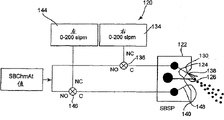
Fig. 8 shows the system that uses triple jet to spray.
Describe in detail
By the following description together with the referenced drawings embodiment of the present invention, above-mentioned and other advantage of the present invention and the mode that obtains them will become more apparent, and the present invention itself will be better understood.
For purposes of the invention, water vapour is defined as the water that is gaseous form, and different from the little water droplet of so-called " mist ". Because mist is the water with the condensation of droplet form, thus when mist be deposited in may the surface corresponding with heat of vaporization on the time basically do not have a clean heating effect. For purposes of the invention, steam is to be in the boiling point of water or above evaporation water, and this boiling point depends on pressure, if for example pressure be 1 atmospheric pressure be 100 ℃ when under the temperature greater than the boiling point of water, providing steam, it is called superheated steam. Water vapour randomly can be by also comprising for example dissolved gas ozone for example of component except water, or inert gas for example the composition of nitrogen provide. Think and can by any means water vapour be supplied with sulfuric acid composite, with basically pure form, or with composition forms, with greater than or be less than or equal to 100 ℃, and provide to have greater than, the water vapor pressure or the dividing potential drop that are less than or equal to 1atm. When for example can be from FSIInternational to spray machining tool, Inc., Chaska, MN is purchasedOr Inject process machine or also can be from FSI International, Chaska, Minnesota is purchased
 System adds man-hour, and method of the present invention can be used to side by side process the polycrystalline board with the batch of material of wafer. The present invention can also be used for the single-chip processed and applied, and wherein wafer is that move or fixing, or is used for batch applications, and wherein wafer is static basically.
With reference to accompanying drawing, wherein same numbering is used for the same member of mark in whole several accompanying drawings:
Fig. 1 shows and works as in the beaker that stirs rapidly 20 ℃ of H2SO
4(98wt%) with 20 ℃ of liquid waters or 20 ℃ of H2O
2The temperature of gained when (30wt%) mixing. In regional A, at the H between 100% and 57% roughly2SO
4Under the volume ratio, this H2SO
4The temperature of/water blend increases with the increase of water content. In regional B, under the ratio between 56% and 36% roughly, this H2SO
4The temperature of/water blend reduces lentamente with the increase of water content. In regional C, under the ratio between 35% and 10% roughly, the temperature of this blend promptly reduces with the water content increase. With H2O
2The H that mixes2SO
4Temperature variation follow identical trend, but maximum temperature is slightly lower. Employing is 57vol%H roughly2SO
4And 43vol%H2O
2The H of blend2SO
4/ water blend obtains the roughly maximum temperaturerise of 110 ℃ (final temperatures of 130 ℃). On apical axis, also show water: H2SO
4The H of blend2O and H2SO
4Mol ratio. Border between zone A and the B is 2: 1 water: H roughly2SO
4, the border between B and the C is roughly 5: 1.
Fig. 2 shows the derived graph of the water interpolation curve of Fig. 1. This shows with H in the solution2SO
4The temperature rise that increases of each percentage of water content of changing of ratio. From 100% to 37%H2SO
4There is almost linear decline in ratio dT/d water. Although be not wishing to be bound by theory, should believe, along with hydrone round each sulfuric acid molecule coordination, the temperature rise of solution (heat of mixing) is just caused by hydration heat. In the present invention, this strong attraction between water and the sulfuric acid molecule drives desiccation, and this desiccation is drawn water vapour and entered in this sulfuric acid composite from atmospheric pressure, even when the temperature of this sulfuric acid composite during greater than the boiling point of water. Under 55vol% sulfuric acid roughly, the thermic load by interpolation water makes this hydration heat balance, and the extra water that adds has clean cooling effect to blend. At 37vol%H roughly2SO
4Lower, H2SO
4Aquation look like completely. Shown in the x axle of Fig. 1 and 2 top, show water in the solution: H2SO
4Mol ratio. When for each mole H2SO
4When having roughly 5 mole of water, aquation looks like completely.
Opposite with Fig. 1, the present invention condenses in the sulfuric acid composite by water vapour water is added in the said composition. This causes not only passing through H2SO
4And H2The heat of mixing between the O, and said composition is heated by the heat of vaporization of water, this heat of vaporization recovers when water condensation is in the sulfuric acid composite. With add liquid water to H2SO
4In compare, the Regong of water vapour heat of vaporization is offered the dilution that allows for specified rate and is obtained bigger temperature and increase.
Fig. 3 A and 3B show an example of the equipment that can be used for implementing technology of the present invention. Fig. 3 A shows the schematic diagram of interrupted injection processor 10, and this processor has shown the main component of a system, comprises chemical substance mixing collector 90, circulating water chennel 50 and processes bowl 12. Equipment 10 be spray that machining tool for example is included in can be from FSI International, Inc., Chaska, MN is purchased OrIn the diagram of instrument.
 Equipment 10 generally includes bowl 12 and the lid 14 that defines Processing Room 16. Wafer-like object 18 (for example, is placed carrier 20 Magazine) in, this
 carrier 20 is remained on the turntable 22 of rotation by turntable bar (not shown) again. Turntable 22 is connected with electric motor driven axle 24. Water or nitrogen can provide and spread to the Processing Room 16 via this turntable bar (not shown) from supply line 32. Also can from supply line 34 one or more chemical substances are provided and spread to the Processing Room 16 via central-injection bar 36 directly to wafer 18 and/or directly to turntable 22 or via pipeline 38 via side jet rod 40 to this wafer.
For example, supply line 34 can be connected with chemical substance recirculating system 49 fluids. This recirculating system can comprise chemical substance supply line 67 and 68. Chemical substance supply line 67 can comprise filter 64 and 66, pump 62 and be connected with recycle furnish groove 50 fluids. Can replenish pipe 52 from recirculation delivery pipe 54 and fresh chemical substance and provide the processing chemical substance to this recycle furnish groove. Blanket of nitrogen 56 can be used for the headroom of groove 50. For the temperature of the processing chemical substance in the control flume 50, groove 50 can comprise heat(ing) coil 58, cooling coil 60 and temperature sensor 41. Chemical substance supply line 68 can provide for example nitrogen and the flushing of DI water. After chemical substance is offered Processing Room 16, any no chemical substance can enter floss hole 70 and enter 71 ° of discharge manifold from this discharge manifold, chemical substance can be sent to various outlets and for example recycle delivery pipe 54, exhaust apparatus 72, DI floss hole 74, auxiliary 76, auxiliary 78, auxiliary 80 and auxiliary 82.
Supply line 34 also can be connected with fresh chemical substance blend collector 90 fluids. In this collector, will mix to form required blend from the controlled fluid of the fresh chemical substance of pipeline 91-94, via pipeline 98 and 34 this blend is delivered to central-injection bar 36 or delivered to side jet rod 40 via pipeline 98 and 38. Randomly, can the chemical substance blend be heated by the online infrared heater (heater does not illustrate) in pipeline 98. Perhaps, can be by being placed on infrared heater in one or more among the pipeline 91-94 with one or more heating in the feed chemical.
The structure of equipment 10 and use further describe in following document: U.S. Patent number 5971368; 6,235,641; 6,274,506 and 6,648,307, and with people's such as Benson name on March 12nd, 2004 submit to have a United States serial 10/799,250 assignee's common unsettled U.S. Patent application, this patented claim be entitled as ROTARYUNIONS, FLUID DELIVERY SYSTEMS, AND RELATED METHODS.
Fig. 3 B shows the representational practice model of use according to equipment 10 of the present invention.Fluid sulphuric acid composition 42 is spread on the wafer 18 with the amount that effectively evenly applies the base material of organic coated materials basically from center jet rod 36 and/or side jet rod 40 (not shown)s.This coating uniformly basically can be by adopting pre-service liquid pre-service (for example, use identical equipment) promote that so that the surface to be provided wherein water/sulfuric acid mol ratio is not more than about 5: 1 fluid sulphuric acid composition (when being coated on this surface) and will applies equably basically on this surface.As mentioned above, for example the precoating of fluid sulphuric acid composition is changing the character of surface of base material for this pretreatment compositions, so that water/sulfuric acid mol ratio follow-up (or continuation) of being not more than about 5: 1 fluid sulphuric acid composition applies and will apply this base material basically equably.Randomly, other surface modification component can be used for this pre-service liquid, for example surfactant or solvent, and their effect is the character of surface that changes this base material as required.Can add additional component so that the chemical modification of preprocessing solution to be provided.For example, small amount of acid can be added in the moisture preprocessing solution.
After scattering liquid sulfuric acid composite 42 (or simultaneously, or before), hot water 44 is spread on the turntable 22.The evaporation of part hot water 44 increases the water vapour capacity (humidity) of chamber atmosphere.Wafer 18 has scribbled the organic material that will remove.In preferred embodiments, this organic material is a photo anti-corrosion agent material.The organic material that requirement is removed is included in during the previous wafer process step by being exposed to pines for the photoresist that toasted.Especially the organic material that requires to remove is those that formerly implanted by heavy ion during the wafer process step.Method of the present invention is being removed aspect the photo anti-corrosion agent material that heavy ion implants especially and effective astoundingly.
Fluid sulphuric acid composition 42 has and is not more than about 5: 1 water/sulfuric acid mol ratio.Therefore, this fluid sulphuric acid composition is restricted aspect liquid water content.In one embodiment, the fluid sulphuric acid composition can comprise solvent, and this solvent can significantly not disturb the water vapour of interpolation subsequently and the coordination of sulfuric acid, as the more detailed argumentation of this paper.Preferred this kind solvent is to be inertia with respect to pending base material (for example wafer), for example fluorine-based liquid.An example of this type of inert solvent comprises can be from 3M, the Fluorinert that St.Paul, MN are purchased
TMSolvent.Should be noted that above-mentioned mol ratio is meant water/sulfuric acid mol ratio, is not solvent/sulfuric acid ratio.This emphasizes this ratio that this solvent can not disturb subsequently the coordination of the water vapour that adds and sulfuric acid significantly and can not influence embodiment of the present invention.
More preferably, the fluid sulphuric acid composition is highly enriched.Preferably, with about at least 80vol%, more preferably about at least 90vol%, most preferably at least approximately the sulfuric acid concentration of 94vol% scatters the liquid sulfuric acid composite.As illustrated in fig. 1 and 2, these high H
2SO
4Concentration condenses to H with respect to per unit
2SO
4Produce maximum temperature rise in the water vapour of composition.
In one embodiment of the invention, fluid sulphuric acid composition 42 comprises hydrogen peroxide.This hydrogen peroxide serves as oxygenant, and it helps organic substance to resolve into CO
2And water.Aptly hydrogen peroxide is provided in the aqueous solution with concentrated sulphuric acid blend to provide water/sulfuric acid mol ratio to be not more than about 5: 1 fluid sulphuric acid composition.Advantageously, the mixing because themopositive reaction produces heat of the concentrated sulphuric acid and aqueous hydrogen peroxide solution, therefore the fluid sulphuric acid composition that can provide the gained that is in high temperature to contain hydrogen peroxide uses still less the energy from special-purpose thermal source to heat said composition simultaneously.This themopositive reaction normally is used for the important thermal source of said composition.Yet in the present invention, the reaction between this sulfuric acid composite and the water vapour provides required heat, and the excessive interpolation of water base hydrogen peroxide can suppress this sulfuric acid-vapor reaction.Therefore, owing to the understanding to the effect of steam in concentrated sulphuric acid composition as herein described, the technician can regulate H now
2O
2Concentration is to optimize H simultaneously
2SO
4The heat that-vapour-phase reaction produces and provide enough reactant with oxidation operation.
In one aspect of the invention, can before the distribution of fluid sulphuric acid composition, during or afterwards oxygenant is introduced process chamber.For example, can be before the fluid sulphuric acid composition be introduced process chamber, perhaps in this process chamber, scatter during this fluid sulphuric acid composition or afterwards hydrogen peroxide is mixed with the liquid concentrated sulphuric acid.Can realize mixing of hydrogen peroxide and the liquid concentrated sulphuric acid by using static mixer or active hybrid technology, maybe this mixing can only be that a kind of solution contact with another kind of solution, wherein mixes and only passes through to spread realization.As required can be similarly with other reagent for example ozone introduce the fluid sulphuric acid composition.Dry oxidation agent for example ozone may be compared H
2O
2Good, because they can not dilute H
2SO
4Composition.For example, remove H
2O
2Oxygenant in addition can be used for sulfuric acid of the present invention-steam technology.For example, can be with ozone, nitric acid, chromate ion (Cr
+ 6) or high cerium ion (Ce
+ 4) be incorporated herein the technology of description.Specifically, these materials can add H to by anhydrous form
2SO
4In, so that this H
2SO
4Maintenance is undiluted relatively.Can also use other oxygenant.
Preferably, at about at least 90 ℃, scatter the liquid sulfuric acid composite under the more preferably about 90 ℃-about 150 ℃ temperature.In another embodiment, preferably under about 95 ℃-about 120 ℃ temperature, scatter the liquid sulfuric acid composite.In another embodiment, in being exposed to water vapour before at about at least 130 ℃, scatter the liquid sulfuric acid composite under the more preferably about 130 ℃-about 200 ℃ temperature.The introducing of fluid sulphuric acid composition 42 makes wafer surface moistening with the sulfuric acid chemical action.Preferably, to provide the amount that is enough to sulfuric acid functional group that the organic material that applies on the wafer 18 is removed that fluid sulphuric acid composition 42 is coated on this wafer.Preferably, with about at least 5 microns, more preferably about at least 10 microns thickness spreads to the fluid sulphuric acid composition on the base material of organic material coating.In one embodiment of the invention, with about 10 microns-about 140 microns thickness, preferably approximately 10 microns-about 60 microns thickness spreads to the fluid sulphuric acid composition on the base material of this organic material coating.
In one embodiment, under the temperature lower, for example under the about 60 ℃ temperature of about 20-, provide wafer 18 than water boiling point.Before the distribution of fluid sulphuric acid composition, during or afterwards, preferably wafer 18 is heated to about at least 90 ℃ temperature.More preferably, wafer 18 is heated to about 90 ℃-about 150 ℃ temperature.In another embodiment, wafer is heated to about 95 ℃-about 120 ℃ temperature.This heating can followingly be carried out: for example, use the radiation heat heated chamber, hot water or other liquid solution are guided on the wafer and before applying concentrated sulphuric acid composition removed heating liquid basically, heated air is introduced chamber etc.If use the liquid heated chip, then before introducing concentrated sulphuric acid composition, remove the liquid of q.s so that this concentrated sulphuric acid composition and keep required sulfuric acid concentration level and then this fluid sulphuric acid composition is exposed to the water vapour from this wafer by directly contacting with wafer.
In one embodiment of the invention, can following wafer be preheated:, promptly discharge the content (for example " pouring out " program rapidly) of this bath and carry out maintenance treatment step as described below the heating bath of one or more wafers immersion liquid.This body lotion body for example can be, DI water, vitriolated DI water, sulfuric acid/hydrogen peroxide mixture, inert fluid (for example fluorohydrocarbon), sulfuric acid/ozone mixture etc.This embodiment can provide sizable interests aspect the turnout that improve treatment process by heated chip more efficiently.Can be used for adopting the especially example of suitable process system of this embodiment is can be from FSIInternational, Chaska, and Minnesota is purchased
System,
In any suitable way water vapour is introduced chamber.Shown in Fig. 3 B, be splashed to downwards on the turntable 22 of rotation from the bottom 46 of center jet rod 36 DI water 44 with heating." spatter down " in the method at this, produced water vapour.Perhaps, can for example in this process chamber, produce water vapour by any suitable place of water steam generating technique by heating in process chamber and/or stirring water.
In another replacement scheme, can outside process chamber, produce water vapour and introduce process chamber by required water vapour form.For example, the outside water vapour that produces can be used as gas, or the component of the potpourri of gas is supplied with this chamber.In one embodiment, can be by with gas (N for example
2) bubbling produces steam by water column (preferred hot water).In another embodiment, this gas can pass through in the surface of big water gaging.In another embodiment, this gas can pass the pouring packed column that is usually used in chemical engineering.In another embodiment, can produce pure basically water vapour by aqueous water is seethed with excitement.The gaseous product that derives from any of these alternatives can further be heated.Other embodiment also is possible.
Preferably, introducing water vapour so that it is exposed in the wafer under about 70 ℃-about 150 ℃ steam temperature.More preferably, introducing water vapour so that it is exposed in the wafer under about 80 ℃-about 110 ℃ steam temperature.At one especially in the advantageous embodiment, introduce water vapour so that it and under about 85 ℃-about 98 ℃ steam temperature, be exposed in the wafer.This embodiment is favourable, and reason is that water vapour produces by above-described " spattering down " method easily.Because water is not in boiling point, thus easier realization current entering control and excessively do not splash.In different favourable embodiments, consequently it is exposed in the wafer under about 100 ℃ steam temperature to introduce water vapour.This embodiment by boiling water under normal condition easy to implement relatively with by conventional steam forming device in container handling or the outside steam that forms.
In another embodiment, provide temperature than the big water vapour of temperature before this fluid sulphuric acid composition is in being exposed to this water vapour.This embodiment provides by the direct heat transmission the direct-fired interests of fluid sulphuric acid composition, and the interests that energy shifts when water vapour condenses in the aforesaid liquid sulfuric acid.In one embodiment, provide temperature greater than about 150 ℃ water vapour for this reason.
Randomly, as required, water vapour can also comprise another kind of reagent, for example hydrogen peroxide or ozone.
Effectively the temperature of fluid sulphuric acid composition is increased to the amount greater than the temperature before this fluid sulphuric acid composition is in being exposed to this water vapour, the amount that also is preferably greater than the temperature of this water vapour is introduced process chamber with water vapour.In one embodiment of the invention, this fluid sulphuric acid composition is exposed in the water vapour, and the amount of this water vapour effectively will be increased to the temperature and the (ii) temperature of this water vapour before simultaneously being exposed in this water vapour greater than the fluid sulphuric acid composition on (i) base material in the temperature of the fluid sulphuric acid composition on this substrate surface.Astoundingly, even when the temperature of fluid sulphuric acid composition near so that during greater than water boiling point, water vapour still associates with mode and this fluid sulphuric acid composition of the temperature that increases this fluid sulphuric acid composition, removes validity thereby improve organic material under the situation that the temperature of this fluid sulphuric acid composition increases.
Preferably, provide enough fluid sulphuric acid composition and water vapour and mixed with about at least 20 ℃ of the temperature increase of fluid sulphuric acid composition, more preferably about at least 40 ℃, more preferably about at least 60 ℃.This is even more important, because the fluid sulphuric acid composition is positioned on the wafer, this wafer itself serves as heating radiator and absorbs sizable energy approaches this fluid sulphuric acid composition with holding temperature temperature.Can measure the temperature of the fluid sulphuric acid composition on the substrate surface by any suitable measuring technique.For purposes of the invention, can make the approximate temperature that during rotating on the turntable 22, is being cast to the liquid on the processing tube wall with measurement at chip carrier of suitable temperature by serviceability temperature sensor 41.In order to implement this measurement, temperature sensor can be arranged in the container handling.In one embodiment, discoloring temperature indication material can be used to indicate the maximum temperature that reaches in the container handling.
In the time of on being positioned at the base material that organic material applies, the exposure of fluid sulphuric acid composition in water vapour can effectively increase whenever carrying out of this fluid sulphuric acid composition temperature.In one embodiment, during the distribution of fluid sulphuric acid composition, water vapour is introduced process chamber.Should be appreciated that in this embodiment, the temperature of fluid sulphuric acid composition can in addition said composition with begin before base material contacts to increase.Difference between temperature when in this embodiment, the temperature increase of fluid sulphuric acid composition as discussed above after in being exposed to water vapour can be regarded as the fluid sulphuric acid composition and scatter and the fluid sulphuric acid composition maximum temperature after in being exposed to water vapour.
In another embodiment of the invention,, but the fluid sulphuric acid composition is offered wafer with a plurality of discrete pulses not with continuous stream.(being the about 3-10 of length second) preferably lacked in these pulses, and is in high flowing (promptly with about 2-81pm flow velocity).Preferably between pulse, there is the about 5-20 period that does not have liquid flow of second.When flow down when operation at pulse liquid, randomly only introduce water vapour, thereby reduce during technology of the present invention the amount of the water vapour that overflows from chamber at impulse duration.Similarly, can be randomly introduce water vapour, improving sulfuric acid composite, or between pulse, introduce, the heating of reinforcement said composition with on base material the time in itself and temperature rise before base material contacts at impulse duration.
In another embodiment, the distribution of stop liquid sulfuric acid composite before introducing water vapour.In aspect of this embodiment, base material is equipped with the immobilising relatively coating of fluid sulphuric acid composition.Randomly, during the distribution of fluid sulphuric acid composition and/or afterwards, and the fluid sulphuric acid composition be exposed in the water vapour during, be slowed to the rotation of base material less than the speed of about 20rpm or stop.Carry out this technology to promote this coating (or " puddles of water ") the keeping on base material of fluid sulphuric acid composition.Though be not wishing to be bound by theory, should believe, because particularly during the fluid sulphuric acid composition is exposed in the water vapour this fluid sulphuric acid composition hardly show ontology move, this liquid inclination on all positions on the base material with the dissolving of similar speed and/or remove undesired material on the substrate surface in addition.The homogeneity of this raising may be owing to the even exposure of fluid sulphuric acid composition in water vapour.Additionally or alternatively, remove undesired material and (specifically, remove SiO
2) raising homogeneity may owing to fluid sulphuric acid composition on this whole coating to the dissolving the even permeation rate of not wanting material.The distribution of this fluid sulphuric acid composition can further following change: by changing flow velocity, and distribution time and change the thickness of this fluid sulphuric acid composition layer by the speed that centrifugal force is removed the fluid sulphuric acid composition.In addition, can following increase do not want the intensity of removing of material: after the steam step, discharge the waste sulfuric acid solution potpourri, apply the fresh layer of sulfuric acid solution potpourri, and steam is introduced chamber once more.
As mentioned above, from jet rod 36 and/or 40 fluid sulphuric acid composition 42 is spread on the wafer 18.In some structure of wafer processing apparatus, the location of jet rod and fluid have been found that the performance that influences technology of the present invention from the direction that this bar flows.In having some wafer processing apparatus that fixedly jet rod is constructed, the fluid of distribution tends to deposit in the mode that partly produces high strength of fluid at wafer.For example, the liquid inclination that scatters from center jet rod 36 is in being deposited on the base material with high concentration near the central-injection bar.In addition, under some orientations of turntable 22, can between wafer, pass and discarded from most liquid of central-injection bar.Advantageously, by using side bowl jet rod 40 (SBSP) can obtain excellent deposition efficiency and homogeneity.But by also tending near the central-injection bar deposit liquid too much with spray that the positive vertical SBSP of chamber directly scatters towards the turning axle of turntable.This vertical injection further is wasted in the liquid that passes by some orientations of this turntable between the wafer.Can followingly observe excellent deposited picture: make liquid be angle with the first type surface that departs from chamber and/or away from the center of turntable from the injection of jet rod (especially SBSP).Though angled injection causes near CSP " concentrating " deposition still less, all angles are not enough to satisfy uniformly and cover.Jet angle is fixed in one embodiment of the invention.In another embodiment of the invention, the turntable of supporting base material the fluid sulphuric acid composition spread on the substrate surface during rotate, and by scattering this fluid sulphuric acid composition to spray this liquid with respect to the angle of turntable variation by the swing mode.In aspect of this embodiment, jet angle changes during the single of fluid sulphuric acid composition scatters.In aspect another of this embodiment, when carrying out repeatedly liquid dissemination in a processing cycle, the spray angle that scatters this fluid sulphuric acid composition is once with different next time.
(or " scanning ") causes the position change that sprays focus to the jet angle of change fluid sulphuric acid composition, causes more uniform liquid deposition.Change firing angle also reduces the blind area by the structural detail of magazine and turntable the influence of spurting in the chip carrier system.Might change the angle of spraying by many methods, for example comprise, make the injection equipment rotation or spray by different angles via a plurality of injection equipments.
The method for optimizing and the equipment that change the injection direction of SBSP40 are illustrated among Fig. 8, the figure shows the system 120 that uses triple jet 122 to spray.In this nozzle, under enough pressure, provide from the liquid of fluid supply (not shown) with by its atomizing of liquids stream 126 for center pit 124.Provide gas via operation valve 136 for pore 130 from gas source 134.Provide gas with 130 jet-stream winds 138 from the hole under the pressure of regulating, this hole 130 makes spray deflection and atomizing simultaneously.Similarly, provide gas via operation valve 146 for pore 140 from gas source 144.Provide gas with 140 jet-stream winds 148 from the hole under the pressure of regulating, this hole 140 makes spray deflection and atomizing simultaneously.Can regulate injection direction to give the flow direction of liquid spray by changing flowing of air-flow 138 and 148.The trickle gradual change of gas flow allows the fine adjustments of injection direction.Obtain the spray pattern vertical from the equal flow of two gas sources with the injection equipment front center.Injection discretely deflection (for example+20 ° 10 seconds, then+30 ° 10 seconds etc.) or scanning continuously.Can for example by the mass flow controller modulation, or can for example modulate discretely at successive range internal modulation gas flow by a plurality of holes.It is especially favourable that 120 pairs of this systems are used for process semiconductor wafers, and reason is that it provides the directivity and the power control of the excellence of liquid injection.In addition, the control that the equipment with moving-member provides this excellence needn't be installed in process chamber.The minimization of the quantity of movable part is wished in the process chamber, introduces short grained possibility in this process chamber because movable part is increased in, and this is owing to the rubbing wear of mobile member.In addition, if equipment is not positioned at process chamber, the use of this equipment is simplified widely.
The fluid sulphuric acid composition is being fixed or is being scanned under the situation that spray to introduce process chamber, the direction of injection preferably with this process chamber in the rotation of base material coordinate.In one embodiment of the invention, when wafer rotates on turntable in chamber, make spray be the wafer that angle enters arrival.That is, make from the spray of side bowl jet rod 40 and during the clockwise rotating of turntable, deflect into the right and during the inhour rotation, deflect into the left side.
In another embodiment of the invention, the blind area influence that the structural elements of magazine and turntable causes and/or excessive the concentrating of some position of liquid in chamber can followingly be improved: arrange the deflection element to press flowing of some direction with interruption or blocking-up spray in chamber.These elements can or cover 14 by bowl 12 and support and be static basically therefore, maybe can support by turntable 22, and therefore be in fixing basically position with respect to rotating wafer.
In embodiments of the invention, thinking can be with the base material pre-service to help to remove from it organic material.For example, the base material that has applied organic material on its part is handled with the composition that contains surfactant before can scattering the liquid sulfuric acid composite thereon.
During described method, also consider additional operating steps, for example by before the fluid sulphuric acid compositions-treated, during or afterwards base material is exposed in million acoustic energies.
The equipment that is used for the inventive method can followingly be prepared: changing known injection processing machine able to programme for example can be from FSI International, Chaska, and Minnesota is with trade name
 Or
In one or more centrifugal atomization processors that are purchased that class, for its chemical substance reservoir provides necessary solution and is used in the controller of this this machine of program setting that needs.Should be appreciated that can revise other known interrupted injection and single-chip similarly sprays machine and implement the present invention.
Or
In one or more centrifugal atomization processors that are purchased that class, for its chemical substance reservoir provides necessary solution and is used in the controller of this this machine of program setting that needs.Should be appreciated that can revise other known interrupted injection and single-chip similarly sprays machine and implement the present invention.
In another embodiment, technology of the present invention also can once be applied to a wafer by " single-chip " pattern.Fig. 7 shows an embodiment of this kind single-chip process equipment 100, and wherein when at chuck (not shown) upper support wafer 103, this chuck is installed on the axle of motor 104, from pipeline 101 sulfuric acid composite 102 is dispersed on this wafer.Introduce water vapour 105 via pipeline 106.This equipment consequently can be kept the steam of desired level in wafer surface in the chamber 107 of enough sealings.
In one embodiment, equipment 100 can adopt sulfuric acid composite to operate from the continuous distribution of pipeline 101, and wherein pipeline 101 is static or moves with respect to wafer 103.Can be before this dissemination, during or afterwards steam is introduced this equipment.
In another embodiment, adopt the moistening entire wafer of sulfuric acid composite and stop distribution, thereby allow said composition on this wafer, to form the film that has than uniform thickness.The more immobilising as mentioned above coating of this fluid sulphuric acid composition can be provided for this wafer in this embodiment.Randomly, slow down or stop this coating the keeping on base material of the rotation of this base material with promotion fluid sulphuric acid composition.Can be before this dissemination, during or afterwards steam is introduced this equipment.Randomly, can repeat to scatter and think that wafer surface provides the fresh supply of reactant.Randomly, can between scattering, promptly rotate this wafer to abandon the most of sulfuric acid composite that is present on the wafer.Randomly, can following thin layer coated wafers: make by the mode that in semi-conductor industry, is used for producing the resist thin layer and to scatter pipeline 101 and move with sulfuric acid composite.
In one embodiment of the invention, sulfuric acid composite leaves the temperature arrival wafer surface of scattering pipeline 101 to be substantially equal to it.In one embodiment, it has to benefit said composition is broken into droplet, and this droplet can absorb steam and heating before contact wafer.This type of droplet can followingly produce: for example, sulfuric acid composite atomized, or allows this sulfuric acid composite pass nozzle with vapor composition or another kind of gas, or other technology.It has and benefits this provenance material of sulfuric acid composite mist that makes through heating and move above wafer.
In one embodiment of the invention, can before leaving distribution pipeline 101, sulfuric acid composite it be preheated by said composition is contacted with the gas of moisture vapor.For example, the gas of moisture vapor can combine with sulfuric acid composite down at " T " in heat-resistant tube (for example quartz ampoule).This embodiment provides following advantage: the sulfuric acid composite when the sulfuric acid composite temperature that is reached can be than blend or the temperature of steam are much higher.
Be to be understood that, the various embodiments of method described here (for example carrying the variant of sulfuric acid composite aspect) are not limited to use with the particular device of accompanying drawing, but can be applicable to application in the possessive construction of handling machine, this handling machine is suitable for the application in implementing current describing method.Now principle of the present invention is described in combination with following illustrative embodiment.
Experimental technique
A. specimen preparation
Be prepared as follows and be used to estimate the sample wafer of implanting the validity of photoresist except that deionization:
Apply the silicon wafer of 200mm diameter with Shipley UV6248nm photoresist.
With some wafer compositions and allow other maintenance have complete resist layer (being respectively patterned wafers and overlayer wafer).
With the energy of 40keV, and 5 * 10
14Or 1 * 10
15Atom cm
2Implant the sample of patterned wafers and overlayer wafer under the dosage of (5E14 or 1E15) simultaneously with arsenic.
Downcut from complete patterning and overlayer wafer resist-coating wafer roughly 2 * 2cm fragment and be attached to High temp. epoxy resins near the center of carrier wafer.Usually five resist samples are attached to each carrier wafer: overlayer resist (not implanting), overlayer 5E14, patterning 5E14, overlayer 1E15 and patterning 1E15.
B. estimate charge stripping efficiency
After processing, by bright field and dark field optical microscopy sample for reference.Table 1 shows the evaluation criterion of overlayer resist sample and patterning resist sample simultaneously.This patterning sample is made of various photoetching test patterns.Fine rule array on the patterning sample and coverlay film peel off measuring with the charge stripping efficiency that deals with.
Table 1
| Score | Explain the patterning resist | Explain the overlayer resist |
| 1 | Thick line and some overlayers stay | In only some undercuts of |
| 2 | Some lines and overlayer stay | The whole surface breakdown of resist |
| 3 | Most of fine rule stays | Remove some resists |
| 4 | Several fine rule stays | The point of resist |
| 5 | There is not visible residual (bright or details in a play not acted out on stage, but told through dialogues) | There is not visible residual (bright or details in a play not acted out on stage, but told through dialogues) |
C. chamber temp is measured
The fluid composition of sulfuric acid/hydrogen peroxide is worked as the temperature that is cast on the process cavity sidewall and is measured by temperature sensor 41.With time interval of one second record temperature and the thermal history of chamber temp in whole process is provided.
D. the temperature survey on the wafer
Following the making of measurement of temperature on the maximum wafer: the point (deriving from Omega Engineering, Stamford, the TL-10 series of CT) that is used in irreversible variable color under the high temperature of regulation is attached to mark on the wafer.The glass sheet that is attached with High temp. epoxy resins with 0.7mm covers this mark and peels off chemical phenomenon so that be protected from.
E. treatment process
Under the following conditions can be from FSI International, Inc., Chaska, MN is purchased
 Spray and handle the wafer of preparation in a manner described in the machining tool:
1. sample wafer is loaded in the slit 13 of 27 chip carrier magazines 20 and fills other slit with exposed wafer.This magazine and the second balance magazine are loaded on the turntable 22.If desired, second sample wafer is loaded in the slit 15.
This turntable 22 with 120rpm rotation and simultaneously from the center 36 and side 40 jet rods will bathe 50 hot H from recycle with the flow velocity of 51pm roughly
2SO
4(110 ℃) are dispersed in wafer last 3 minute.During last about 1 minute of this distribution with 50cc/min H
2O
2Add in this fluid.This step is used for simultaneously wafer being preheated and is moistening fully.
3. this turntable scatters from the fresh sulfuric acid composite (H that mixes collector 90 with the 120rpm rotation and from center jet rod 36
2SO
4And H
2O
2-SPM) the 900cc/min fluid 30 seconds of potpourri.Adding H
2O
2Before by online IR well heater with this H
2SO
4 Preheat 95 ℃.The blending ratio of SPM composition changes as table 2 is listed between handling.
4. technology as above 3 is proceeded.Just, in the present invention handles, the DI water 44 of 95 ℃ of about 81pm is spread to 22 last 6 minutes of turntable to produce water vapour.
5. after washing six minutes, with 80 ℃ of SC-1 solution (NH with DI water
4OH: H
2O
2: H
21: 1: 15 volume ratio of O) handled this sample 75 seconds.
6. wash this sample with DI water and at N
2Middle dry.
Table 2
| Embodiment handles rules | H 2SO 4/H 2O 2Blending ratio | The water vapor that adds | Temperature on the maximum wafer (℃) | Maximum side bowl temperature (℃) |
| 1 | 20∶1 | Be | 204 | 159 |
| 2 (contrasts) | 20∶1 | Not | 93 | 60 |
| 3 | 10∶1 | Be | 154 | 50 |
| 4 (contrasts) | 10∶1 | Not | 62 | 37 |
| 5 | 5∶1 | Be | 126 | 45 |
| 6 (contrasts) | 5∶1 | Not | 78 | 43 |
| 7 | 2.17∶1 | Be | 145 | 54 |
| 8 (contrasts) | 2.17∶1 | Not | 72 | 32 |
Embodiment
Embodiment 1: twice of the treatment process E on 10: 1 blends that have and do not add water vapour ( rules 3 and 4 of table 2) carry out that uses SPM.Measure the temperature of the liquid that abandons against chamber wall by side bowl temperature sensor 41.Fig. 4 shows the temperature variation of these two processing.In both cases, H
2SO
4The 51pm recirculated fluid at first this side bowl sensor is heated to about 65 ℃ in three minutes in this processing.From 3 to 9 minutes, " SPM " comparative example's sensor temperature descended near about 7 ℃ to 58 ℃.On the contrary, " SPM+ water vapour " embodiment of the invention rises 60 ℃ to 125 ℃ during identical.In chamber, add water vapour and increase the temperature that abandons liquid significantly.
Embodiment 2: 8 rules of use table 2 are carried out top treatment process E8 time.Scatter the maximum temperature that abandons liquid (for example 540 of Fig. 4 seconds readings) that adopts 41 each processing of measurement of side bowl temperature sensor when step finishes at SPM.Adopt the temperature-sensitive mark to measure temperature on the maximum wafer.Temperature (being calculated by Fig. 1) (was used and is preheated 95 ℃ H by online IR well heater when Fig. 5 showed the blend of SPM of each processing
2SO
4), temperature and maximum side bowl temperature on the maximum wafer.The temperature of SPM is with H during blend
2O
2Increase (the H of concentration
2SO
4Reduce) rise.On comparative example's the maximum wafer and side bowl temperature also with H
2O
2Concentration increases and rises, but temperature is low during more than the blend of SPM.
On the contrary, adopt the present invention of water vapour to handle temperature on the wafer that obtains high 50-100 ℃ of comparison ratio processing.These temperature of the present invention are also compared higher significantly than SPM temperature on vapor (steam) temperature among the embodiment or the wafer.(representative SPM temperature on base material before steam exposes is handled in contrast).
In addition, the temperature rise between contrast processing and the present invention handle is with H
2O
2Concentration increases and reduces.Temperature difference between the temperature on SPM and maximum wafer when Fig. 6 shows blend.The interests of steam technology of the present invention are with H
2SO
4The reduction of concentration and reducing.Be used for reaching temperature on the maximum wafer, H
2SO
4High concentration be desirable.
By increasing H
2SO
4, H
2O
2Or both pre-blend temperature when increasing blend the temperature of liquid also wished.An embodiment will be utilized at the H greater than 95 ℃ of following circulating water chennels of operating
2SO
4
Embodiment 3: 8 rules of use table 2 are carried out top treatment process E8 time.Processing has the carrier wafer of the sample of patterning and overlayer, 5E14 and 1E15 implantation resist in the slit 13 of magazine.Table 3 shows the result according to the criterion assess sample in the table 1.In all cases, contrast is handled ( rules 2,4,6 and 8) and is failed to remove up hill and dale this implantation resist and score " 1 " in all are estimated.On the contrary, the present invention handles ( rules 1,3,5 and 7) and fully removes patterning and overlayer 5E14 resist, score " 5 " in all are estimated.
Though show to such an extent that comparison is more much better than handling, the specific rules of these of technology of the present invention can not fully be removed 1E15 and be implanted resist.Rules 1,3 and 5 performances are similar, almost remove the patterning resist.7 pairs of overlayer resists of rules show better slightly, but very different to the patterning resist.In order to reach maximum stripping performance, H
2SO
4High concentration be desirable.
Table 3
| Embodiment handles rules | 5E14 ion implant on the patterning resist | 5E14 ion implant on the overlayer resist | 1E15 ion implant on the patterning resist | 1E15 ion implant on the overlayer resist |
| 1 | 5 | 5 | 4 | 2 |
| 2 (contrasts) | 1 | 1 | 1 | 1 |
| 3 | 5 | 5 | 4 | 2 |
| 4 (contrasts) | 1 | 1 | 1 | 1 |
| 5 | 5 | 5 | 4 | 2 |
| 6 (contrasts | 1 | 1 | 1 | 1 |
| 7 | 5 | 5 | 4 | 3 |
| 8 (contrasts) | 1 | 1 | 1 | 1 |
Embodiment 4: the modified that 1E15 overlayer and patterned wafers sample is carried out top treatment process E.This technology is as follows:
Scatter fresh 9 by two stages from the center jet rod: 1000cc/m fluid (900cc/m95 ℃ the H of 1SPM
2SO
4H with 100cc/m20 ℃
2O
2): at 120rpm) following 180 seconds clockwise, 120rpm following 180 seconds counterclockwise.The water that scatters 81pm95 ℃ on turntable is to produce water vapour.
The reverse combination of the chemical substance exposure time that increases, ascending temperature and rotation causes patterning and overlayer 1E15 to implant the removing fully of resist (all scores " 5 ").
Embodiment 5: in some cases, need not oxygenant is added in the sulfuric acid composite, because the resist of not implanting or slightly implanting can pass through H separately usually
2SO
4Remove.For example, under 120rpm, scatter 95 ℃ of H from circulating water chennel from center and side jet rod
2SO
4 51pm fluid 3 minutes.The covering resist of not implanting is fully removed in this processing.
Except as otherwise noted, employed all percent of this paper and ratio are percentage by volume and volume ratio.Atmospheric environmental pressure of all temperature supposition of quoting.Should be appreciated that the temperature of the various components that relate in this technology can correspondingly be regulated if carry out treatment process under different pressure.All publications, patent and the patent document quoted are hereby incorporated by data fully, just as being introduced separately into conduct with reference to data.Many feature and advantage that hope of the present invention is described by this document have been set forth in the foregoing description.Yet, though should be appreciated that for example clear particular form of the present invention or embodiment, under the situation that does not break away from the spirit and scope of the present invention, can make various changes, comprise the change of shape and the layout of parts etc.
Claims (2)
1. change method, may further comprise the steps from the liquid injection direction of three hole nozzles:
A) provide nozzle, it has
I) have first hole from the liquid of fluid supply, its under enough pressure from its atomizing of liquids stream;
Ii) have first pore from the gas of gas source, with the pressure of regulating provide this gas with from this first pore gas jet stream so that this flow of liquid deflection at least in part;
Iii) have second pore from second gas of second gas source, with the pressure of regulating provide gas with from second pore gas jet stream so that this flow of liquid deflection at least in part; With
B) regulate liquid and think from the flow of liquid of center pit from the injection direction of nozzle and give direction by changing first pore and second pore air flow rate one of at least.
2. the process of claim 1 wherein and during treatment process, pass through to regulate the injection direction of the gas flow change of first pore and second pore from the liquid of nozzle.
Applications Claiming Priority (2)
| Application Number | Priority Date | Filing Date | Title |
|---|---|---|---|
| US73972705P | 2005-11-23 | 2005-11-23 | |
| US60/739,727 | 2005-11-23 |
Related Parent Applications (1)
| Application Number | Title | Priority Date | Filing Date |
|---|---|---|---|
| CN2006800437106A Division CN101312794B (en) | 2005-11-23 | 2006-11-22 | Process for removing material from substrates |
Publications (1)
| Publication Number | Publication Date |
|---|---|
| CN101900956A true CN101900956A (en) | 2010-12-01 |
Family
ID=37951429
Family Applications (2)
| Application Number | Title | Priority Date | Filing Date |
|---|---|---|---|
| CN2006800437106A Active CN101312794B (en) | 2005-11-23 | 2006-11-22 | Process for removing material from substrates |
| CN2010102133298A Pending CN101900956A (en) | 2005-11-23 | 2006-11-22 | Remove the method for material from base material |
Family Applications Before (1)
| Application Number | Title | Priority Date | Filing Date |
|---|---|---|---|
| CN2006800437106A Active CN101312794B (en) | 2005-11-23 | 2006-11-22 | Process for removing material from substrates |
Country Status (6)
| Country | Link |
|---|---|
| US (3) | US7592264B2 (en) |
| JP (4) | JP4728402B2 (en) |
| KR (2) | KR20090130197A (en) |
| CN (2) | CN101312794B (en) |
| TW (1) | TWI406110B (en) |
| WO (1) | WO2007062111A1 (en) |
Cited By (2)
| Publication number | Priority date | Publication date | Assignee | Title |
|---|---|---|---|---|
| CN110137111A (en) * | 2019-05-23 | 2019-08-16 | 德淮半导体有限公司 | Gas distributing device and its application method |
| CN116672104A (en) * | 2023-08-04 | 2023-09-01 | 山东第一医科大学附属省立医院(山东省立医院) | Surgical instrument cleaning and sterilizing device for hand and foot surgery |
Families Citing this family (45)
| Publication number | Priority date | Publication date | Assignee | Title |
|---|---|---|---|---|
| JP4672487B2 (en) * | 2005-08-26 | 2011-04-20 | 大日本スクリーン製造株式会社 | Resist removing method and resist removing apparatus |
| KR20090130197A (en) * | 2005-11-23 | 2009-12-18 | 에프 에스 아이 인터내셔날,인코포레이티드 | Process for removing material from substrates |
| US7727900B2 (en) * | 2006-02-21 | 2010-06-01 | Taiwan Semiconductor Manufacturing Co., Ltd. | Surface preparation for gate oxide formation that avoids chemical oxide formation |
| EP1950326A1 (en) * | 2007-01-29 | 2008-07-30 | Interuniversitair Microelektronica Centrum | Method for removal of bulk metal contamination from III-V semiconductor substrates |
| JP5173500B2 (en) | 2008-03-11 | 2013-04-03 | 大日本スクリーン製造株式会社 | Processing liquid supply apparatus and substrate processing apparatus including the same |
| US8142571B2 (en) * | 2008-05-15 | 2012-03-27 | Fsi International, Inc. | Process for treatment of semiconductor wafer using water vapor containing environment |
| KR101421752B1 (en) * | 2008-10-21 | 2014-07-22 | 도쿄엘렉트론가부시키가이샤 | Substrate processing apparatus and substrate processing method |
| JP5330793B2 (en) * | 2008-10-21 | 2013-10-30 | 東京エレクトロン株式会社 | Substrate processing apparatus and substrate processing method |
| US20100124410A1 (en) * | 2008-11-18 | 2010-05-20 | Fsi International, Inc. | System for supplying water vapor in semiconductor wafer treatment |
| KR101294462B1 (en) * | 2008-12-30 | 2013-08-07 | 에이펫(주) | Substrate processing apparatus |
| US8216384B2 (en) * | 2009-01-15 | 2012-07-10 | Intermolecular, Inc. | Combinatorial approach to the development of cleaning formulations for wet removal of high dose implant photoresist |
| US8053301B2 (en) * | 2009-03-30 | 2011-11-08 | International Business Machines Corporation | CMOS SiGe channel pFET and Si channel nFET devices with minimal STI recess |
| JP5745913B2 (en) * | 2010-07-12 | 2015-07-08 | 富士フイルム株式会社 | Radiation image detection device |
| US8709165B2 (en) | 2010-12-03 | 2014-04-29 | Lam Research Ag | Method and apparatus for surface treatment using inorganic acid and ozone |
| CN110189995A (en) | 2010-12-10 | 2019-08-30 | 东京毅力科创Fsi公司 | Method for selectively removing nitride from substrate |
| JP5280473B2 (en) * | 2011-03-03 | 2013-09-04 | 東京エレクトロン株式会社 | Etching method, etching apparatus and storage medium |
| JP2013004614A (en) * | 2011-06-14 | 2013-01-07 | Toshiba Corp | Coating film forming method and coating film forming device |
| US9412628B2 (en) | 2011-06-30 | 2016-08-09 | Tel Fsi, Inc. | Acid treatment strategies useful to fabricate microelectronic devices and precursors thereof |
| CN102923936B (en) * | 2011-08-11 | 2014-12-10 | 富泰华工业(深圳)有限公司 | Etching device |
| JP5837787B2 (en) * | 2011-09-28 | 2015-12-24 | 株式会社Screenホールディングス | Substrate processing equipment |
| TWI444234B (en) * | 2011-10-07 | 2014-07-11 | Univ Chang Gung | Dye adsorption system |
| US8664014B2 (en) | 2011-11-17 | 2014-03-04 | Intermolecular, Inc. | High productivity combinatorial workflow for photoresist strip applications |
| US8940103B2 (en) | 2012-03-06 | 2015-01-27 | Tokyo Electron Limited | Sequential stage mixing for single substrate strip processing |
| US9075318B2 (en) | 2012-03-07 | 2015-07-07 | Tokyo Electron Limited | Sequential stage mixing for a resist batch strip process |
| JP5832397B2 (en) * | 2012-06-22 | 2015-12-16 | 東京エレクトロン株式会社 | Substrate processing apparatus and substrate processing method |
| US9875916B2 (en) | 2012-07-09 | 2018-01-23 | Tokyo Electron Limited | Method of stripping photoresist on a single substrate system |
| JP6168271B2 (en) * | 2012-08-08 | 2017-07-26 | 株式会社Screenホールディングス | Substrate processing apparatus and substrate processing method |
| CN102799083A (en) * | 2012-08-29 | 2012-11-28 | 上海宏力半导体制造有限公司 | Photoresist removal system and photoetching device |
| US10249509B2 (en) | 2012-11-09 | 2019-04-02 | Tokyo Electron Limited | Substrate cleaning method and system using atmospheric pressure atomic oxygen |
| US9513556B2 (en) * | 2012-11-19 | 2016-12-06 | Tokyo Electron Limited | Method and system of process chemical temperature control using an injection nozzle |
| US9735026B2 (en) | 2012-11-27 | 2017-08-15 | Tokyo Electron Limited | Controlling cleaning of a layer on a substrate using nozzles |
| US8871108B2 (en) * | 2013-01-22 | 2014-10-28 | Tel Fsi, Inc. | Process for removing carbon material from substrates |
| US9017568B2 (en) | 2013-01-22 | 2015-04-28 | Tel Fsi, Inc. | Process for increasing the hydrophilicity of silicon surfaces following HF treatment |
| JP6148475B2 (en) * | 2013-01-25 | 2017-06-14 | 株式会社東芝 | Semiconductor manufacturing apparatus and semiconductor device manufacturing method |
| CN103286091B (en) * | 2013-06-09 | 2017-09-19 | 京东方科技集团股份有限公司 | A kind of cleaning method of substrate |
| JP6204213B2 (en) * | 2014-01-28 | 2017-09-27 | 東京エレクトロン株式会社 | Substrate processing method and substrate processing apparatus |
| TWI629720B (en) | 2015-09-30 | 2018-07-11 | 東京威力科創股份有限公司 | Method and apparatus for dynamic control of the temperature of a wet etch process |
| US9768017B1 (en) | 2016-03-15 | 2017-09-19 | United Microelectronics Corporation | Method of epitaxial structure formation in a semiconductor |
| JP6811247B2 (en) | 2016-09-30 | 2021-01-13 | 東京応化工業株式会社 | Cleaning composition, cleaning method, and semiconductor manufacturing method |
| US11355362B2 (en) * | 2017-04-25 | 2022-06-07 | Tokyo Ohka Kogyo Co., Ltd. | Washing method, washing device, storage medium, and washing composition |
| CN109936924A (en) * | 2019-03-06 | 2019-06-25 | 信丰福昌发电子有限公司 | A kind of HDI circuit board etching equipment |
| JP2022099107A (en) * | 2020-12-22 | 2022-07-04 | 東京エレクトロン株式会社 | Substrate processing method and substrate processing device |
| KR102444967B1 (en) * | 2021-04-29 | 2022-09-16 | 에스케이씨솔믹스 주식회사 | Blank mask and photomask using the same |
| KR102465982B1 (en) * | 2021-07-13 | 2022-11-09 | 에스케이씨솔믹스 주식회사 | Blank mask and photomask using the same |
| KR102503790B1 (en) * | 2021-10-07 | 2023-02-23 | 에스케이엔펄스 주식회사 | Blank mask and photomask using the same |
Family Cites Families (128)
| Publication number | Priority date | Publication date | Assignee | Title |
|---|---|---|---|---|
| US703216A (en) * | 1902-03-10 | 1902-06-24 | James W Rickey | Water-wheel-penstock construction. |
| US5845846A (en) | 1969-12-17 | 1998-12-08 | Fujisaki Electric Co., Ltd. | Spraying nozzle and method for ejecting liquid as fine particles |
| SU865975A1 (en) * | 1980-01-30 | 1981-09-23 | Уральский научно-исследовательский институт трубной промышленности | Method of pickling steel articles |
| JPS60177466A (en) * | 1984-02-22 | 1985-09-11 | Sharp Corp | Control system of floppy disc drive |
| US4727512A (en) * | 1984-12-06 | 1988-02-23 | Computer Design & Applications, Inc. | Interface adaptor emulating magnetic tape drive |
| US4778536A (en) * | 1985-06-13 | 1988-10-18 | Purusar Corporation | Sulfur trioxide vapor phase stripping |
| US5872669A (en) * | 1988-03-01 | 1999-02-16 | Seagate Technology, Inc. | Disk drive apparatus with power conservation capability |
| US5438674A (en) * | 1988-04-05 | 1995-08-01 | Data/Ware Development, Inc. | Optical disk system emulating magnetic tape units |
| US5235695A (en) * | 1989-06-28 | 1993-08-10 | International Business Machines Corporation | Apparatus for efficient utilization of removable data recording media |
| JPH0338628A (en) * | 1989-07-05 | 1991-02-19 | Fuji Photo Film Co Ltd | Camera and photographic printing method |
| JP3122819B2 (en) * | 1990-04-11 | 2001-01-09 | ノードソン株式会社 | Method of deflecting and distributing liquid or melt flowing out of nozzle hole by gas jet from surrounding area |
| US5037506A (en) * | 1990-09-06 | 1991-08-06 | Subhash Gupta | Method of stripping layers of organic materials |
| US5274799A (en) * | 1991-01-04 | 1993-12-28 | Array Technology Corporation | Storage device array architecture with copyback cache |
| US5297124A (en) * | 1992-04-24 | 1994-03-22 | Miltope Corporation | Tape drive emulation system for a disk drive |
| JPH05304089A (en) * | 1992-04-28 | 1993-11-16 | Dainippon Screen Mfg Co Ltd | Method and device of removing resist from surface of substrate |
| JPH05304126A (en) * | 1992-04-28 | 1993-11-16 | Dainippon Screen Mfg Co Ltd | Method and system for removing organic compound from surface of substrate in vapor phase |
| US5485321A (en) * | 1993-12-29 | 1996-01-16 | Storage Technology Corporation | Format and method for recording optimization |
| JP3377294B2 (en) * | 1994-06-03 | 2003-02-17 | 大日本スクリーン製造株式会社 | Substrate surface treatment method and apparatus |
| US5864346A (en) * | 1994-09-12 | 1999-01-26 | Nintendo Co., Ltd. | Picture display unit and image display system |
| US5774292A (en) * | 1995-04-13 | 1998-06-30 | International Business Machines Corporation | Disk drive power management system and method |
| KR0146076B1 (en) * | 1995-06-28 | 1998-08-01 | 문정환 | A voltage regulator device for substrate of semiconductor device |
| JP3690619B2 (en) * | 1996-01-12 | 2005-08-31 | 忠弘 大見 | Cleaning method and cleaning device |
| US5785875A (en) * | 1996-02-13 | 1998-07-28 | Micron Technology, Inc. | Photoresist removal process using heated solvent vapor |
| US5774715A (en) * | 1996-03-27 | 1998-06-30 | Sun Microsystems, Inc. | File system level compression using holes |
| US5998305A (en) * | 1996-03-29 | 1999-12-07 | Praxair Technology, Inc. | Removal of carbon from substrate surfaces |
| US6408359B1 (en) * | 1996-04-30 | 2002-06-18 | Matsushita Electric Industrial Co., Ltd. | Storage device management system and method for distributively storing data in a plurality of storage devices |
| WO1997050019A1 (en) * | 1996-06-25 | 1997-12-31 | Cfm Technologies, Inc. | Improved method for sulfuric acid resist stripping |
| US6021408A (en) * | 1996-09-12 | 2000-02-01 | Veritas Software Corp. | Methods for operating a log device |
| US5861064A (en) * | 1997-03-17 | 1999-01-19 | Fsi Int Inc | Process for enhanced photoresist removal in conjunction with various methods and chemistries |
| US20020157686A1 (en) | 1997-05-09 | 2002-10-31 | Semitool, Inc. | Process and apparatus for treating a workpiece such as a semiconductor wafer |
| US6869487B1 (en) * | 1997-05-09 | 2005-03-22 | Semitool, Inc. | Process and apparatus for treating a workpiece such as a semiconductor wafer |
| US6098148A (en) * | 1997-05-29 | 2000-08-01 | International Business Machines Corporation | Storage and access of data using volume trailer |
| US6041329A (en) * | 1997-05-29 | 2000-03-21 | International Business Machines Corporation | Automated message processing system configured to automatically manage introduction of removable data storage media into media library |
| US6578120B1 (en) * | 1997-06-24 | 2003-06-10 | International Business Machines Corporation | Synchronization and resynchronization of loosely-coupled copy operations between a primary and a remote secondary DASD volume under concurrent updating |
| US6389503B1 (en) * | 1997-08-04 | 2002-05-14 | Exabyte Corporation | Tape drive emulation by removable disk drive and media formatted therefor |
| US6173359B1 (en) * | 1997-08-27 | 2001-01-09 | International Business Machines Corp. | Storage and access to scratch mounts in VTS system |
| US5971368A (en) | 1997-10-29 | 1999-10-26 | Fsi International, Inc. | System to increase the quantity of dissolved gas in a liquid and to maintain the increased quantity of dissolved gas in the liquid until utilized |
| US6044442A (en) * | 1997-11-21 | 2000-03-28 | International Business Machines Corporation | External partitioning of an automated data storage library into multiple virtual libraries for access by a plurality of hosts |
| US6105037A (en) * | 1997-12-12 | 2000-08-15 | International Business Machines Corporation | Apparatus for performing automated reconcile control in a virtual tape system |
| US6023709A (en) * | 1997-12-15 | 2000-02-08 | International Business Machines Corporation | Automated file error classification and correction in a hierarchical storage management system |
| US6061309A (en) * | 1997-12-17 | 2000-05-09 | International Business Machines Corporation | Method and apparatus for maintaining states of an operator panel and convenience input/output station of a dual library manager/dual accessor controller system in the event of a failure to one controller |
| US6029179A (en) * | 1997-12-18 | 2000-02-22 | International Business Machines Corporation | Automated read-only volume processing in a virtual tape server |
| US6725331B1 (en) * | 1998-01-07 | 2004-04-20 | Emc Corporation | Method and apparatus for managing the dynamic assignment resources in a data storage system |
| US6231775B1 (en) * | 1998-01-28 | 2001-05-15 | Anon, Inc. | Process for ashing organic materials from substrates |
| US6146469A (en) | 1998-02-25 | 2000-11-14 | Gamma Precision Technology | Apparatus and method for cleaning semiconductor wafers |
| US6234641B1 (en) * | 1998-02-27 | 2001-05-22 | Kenneth R. Ungard | Electroluminescent lamp kit |
| WO1999049998A1 (en) * | 1998-03-30 | 1999-10-07 | The Regents Of The University Of California | Composition and method for removing photoresist materials from electronic components |
| US6260110B1 (en) * | 1998-04-02 | 2001-07-10 | Emc Corporation | Virtual tape system with variable size |
| US6070224A (en) * | 1998-04-02 | 2000-05-30 | Emc Corporation | Virtual tape system |
| DE69914917T2 (en) * | 1998-04-16 | 2005-01-05 | Semitool, Inc., Kalispell | Method and apparatus for treating a workpiece, such as a semiconductor wafer |
| US6269423B1 (en) * | 1998-05-13 | 2001-07-31 | International Business Machines Corporation | Method and apparatus for providing improved caching for a virtual tape server |
| US6067587A (en) * | 1998-06-17 | 2000-05-23 | Sutmyn Storage Corporation | Method for serializing and synchronizing data packets by utilizing a physical lock system and a control data structure for mutual exclusion lock |
| US20020095557A1 (en) * | 1998-06-22 | 2002-07-18 | Colin Constable | Virtual data storage (VDS) system |
| JP3618552B2 (en) * | 1998-06-30 | 2005-02-09 | 富士通株式会社 | Storage device |
| US6353837B1 (en) * | 1998-06-30 | 2002-03-05 | Emc Corporation | Method and apparatus providing mass storage access from systems using different meta-data formats |
| US6049848A (en) * | 1998-07-15 | 2000-04-11 | Sutmyn Storage Corporation | System and method for performing high-speed tape positioning operations |
| US6195730B1 (en) * | 1998-07-24 | 2001-02-27 | Storage Technology Corporation | Computer system with storage device mapping input/output processor |
| US6269431B1 (en) * | 1998-08-13 | 2001-07-31 | Emc Corporation | Virtual storage and block level direct access of secondary storage for recovery of backup data |
| JP3507710B2 (en) * | 1998-09-11 | 2004-03-15 | 株式会社東芝 | Power supply circuit in electrical equipment |
| US6266784B1 (en) * | 1998-09-15 | 2001-07-24 | International Business Machines Corporation | Direct storage of recovery plan file on remote server for disaster recovery and storage management thereof |
| US6235641B1 (en) * | 1998-10-30 | 2001-05-22 | Fsi International Inc. | Method and system to control the concentration of dissolved gas in a liquid |
| US6247096B1 (en) * | 1998-11-02 | 2001-06-12 | International Business Machines Corporation | Handling eject requests of logical volumes in a data storage subsystem |
| US6354922B1 (en) | 1999-08-20 | 2002-03-12 | Ebara Corporation | Polishing apparatus |
| US6336173B1 (en) * | 1999-04-01 | 2002-01-01 | International Business Machines Corporation | Storing and tracking multiple copies of data in data storage libraries |
| US6406551B1 (en) * | 1999-05-14 | 2002-06-18 | Fsi International, Inc. | Method for treating a substrate with heat sensitive agents |
| US6274506B1 (en) * | 1999-05-14 | 2001-08-14 | Fsi International, Inc. | Apparatus and method for dispensing processing fluid toward a substrate surface |
| US6360232B1 (en) * | 1999-06-02 | 2002-03-19 | International Business Machines Corporation | Disaster recovery method for a removable media library |
| US6267301B1 (en) | 1999-06-11 | 2001-07-31 | Spraying Systems Co. | Air atomizing nozzle assembly with improved air cap |
| JP3544329B2 (en) * | 1999-12-14 | 2004-07-21 | 東京エレクトロン株式会社 | Substrate processing equipment |
| US6336163B1 (en) * | 1999-07-30 | 2002-01-01 | International Business Machines Corporation | Method and article of manufacture for inserting volumes for import into a virtual tape server |
| US6610168B1 (en) | 1999-08-12 | 2003-08-26 | Sipec Corporation | Resist film removal apparatus and resist film removal method |
| US6689284B1 (en) * | 1999-09-29 | 2004-02-10 | Kabushiki Kaisha Toshiba | Surface treating method |
| JP2001118820A (en) * | 1999-10-20 | 2001-04-27 | Seiko Epson Corp | Washing device and method |
| US7203732B2 (en) * | 1999-11-11 | 2007-04-10 | Miralink Corporation | Flexible remote data mirroring |
| US7364625B2 (en) * | 2000-05-30 | 2008-04-29 | Fsi International, Inc. | Rinsing processes and equipment |
| CA2381189A1 (en) * | 2000-06-02 | 2001-12-13 | Inrange Technologies Corporation | Message queue server system |
| US6766520B1 (en) * | 2000-06-08 | 2004-07-20 | Unisys Corporation | Tape drive emulation software objects, and emulation of other peripheral systems for computers |
| US6418945B1 (en) * | 2000-07-07 | 2002-07-16 | Semitool, Inc. | Dual cassette centrifugal processor |
| JP3344994B2 (en) * | 2000-08-22 | 2002-11-18 | 株式会社半導体先端テクノロジーズ | Resist stripping apparatus and resist stripping method |
| JP2002074811A (en) * | 2000-08-30 | 2002-03-15 | Nec Corp | System and method for controlling power supply |
| US6694447B1 (en) * | 2000-09-29 | 2004-02-17 | Sun Microsystems, Inc. | Apparatus and method for increasing application availability during a disaster fail-back |
| US6451118B1 (en) | 2000-11-14 | 2002-09-17 | Anon, Inc. | Cluster tool architecture for sulfur trioxide processing |
| US6557089B1 (en) * | 2000-11-28 | 2003-04-29 | International Business Machines Corporation | Backup by ID-suppressed instant virtual copy then physical backup copy with ID reintroduced |
| US20020083265A1 (en) * | 2000-12-26 | 2002-06-27 | Brough Farrell Lynn | Methods for increasing cache capacity |
| JP4034519B2 (en) * | 2001-02-06 | 2008-01-16 | 株式会社東芝 | Wafer cleaning apparatus and wafer cleaning method |
| US6584989B2 (en) * | 2001-04-17 | 2003-07-01 | International Business Machines Corporation | Apparatus and method for wet cleaning |
| US6867148B2 (en) * | 2001-05-16 | 2005-03-15 | Micron Technology, Inc. | Removal of organic material in integrated circuit fabrication using ozonated organic acid solutions |
| US6598805B2 (en) * | 2001-05-30 | 2003-07-29 | Dainippon Screen Mfg. Co., Ltd | Substrate cleaning apparatus |
| US6915397B2 (en) * | 2001-06-01 | 2005-07-05 | Hewlett-Packard Development Company, L.P. | System and method for generating point in time storage copy |
| US6745212B2 (en) * | 2001-06-27 | 2004-06-01 | International Business Machines Corporation | Preferential caching of uncopied logical volumes in an IBM peer-to-peer virtual tape server |
| JP2003017455A (en) * | 2001-07-04 | 2003-01-17 | Seiko Epson Corp | Method and apparatus for treating substrate, and method for manufacturing electronic device |
| US6625704B2 (en) * | 2001-08-08 | 2003-09-23 | Sangate Systems, Inc. | Data backup method and system using snapshot and virtual tape |
| US6877016B1 (en) * | 2001-09-13 | 2005-04-05 | Unisys Corporation | Method of capturing a physically consistent mirrored snapshot of an online database |
| US20030120676A1 (en) * | 2001-12-21 | 2003-06-26 | Sanrise Group, Inc. | Methods and apparatus for pass-through data block movement with virtual storage appliances |
| US7139885B2 (en) * | 2001-12-27 | 2006-11-21 | Hitachi, Ltd. | Method and apparatus for managing storage based replication |
| US20030135672A1 (en) * | 2002-01-14 | 2003-07-17 | Imation Corp. | System having tape drive emulator and data cartridge carrying a non-tape storage medium |
| US20030190870A1 (en) * | 2002-04-03 | 2003-10-09 | Applied Materials, Inc. | Cleaning ceramic surfaces |
| JP4038556B2 (en) * | 2002-04-16 | 2008-01-30 | リアライズ・アドバンストテクノロジ株式会社 | Resist film removing apparatus, resist film removing method, organic substance removing apparatus, and organic substance removing method |
| US20040015731A1 (en) * | 2002-07-16 | 2004-01-22 | International Business Machines Corporation | Intelligent data management fo hard disk drive |
| US20040098244A1 (en) * | 2002-11-14 | 2004-05-20 | Imation Corp. | Method and system for emulating tape storage format using a non-tape storage medium |
| US6908565B2 (en) * | 2002-12-24 | 2005-06-21 | Intel Corporation | Etch thinning techniques for wafer-to-wafer vertical stacks |
| CN1321755C (en) * | 2003-01-21 | 2007-06-20 | 友达光电股份有限公司 | Method for rinsing surface of silicon and technique for manufacturing thin film transistory by using the rinsing method |
| US7055009B2 (en) * | 2003-03-21 | 2006-05-30 | International Business Machines Corporation | Method, system, and program for establishing and maintaining a point-in-time copy |
| US20050010529A1 (en) * | 2003-07-08 | 2005-01-13 | Zalewski Stephen H. | Method and apparatus for building a complete data protection scheme |
| US7953819B2 (en) * | 2003-08-22 | 2011-05-31 | Emc Corporation | Multi-protocol sharable virtual storage objects |
| US7287133B2 (en) * | 2004-08-24 | 2007-10-23 | Symantec Operating Corporation | Systems and methods for providing a modification history for a location within a data store |
| US7991748B2 (en) * | 2003-09-23 | 2011-08-02 | Symantec Corporation | Virtual data store creation and use |
| US7827362B2 (en) * | 2004-08-24 | 2010-11-02 | Symantec Corporation | Systems, apparatus, and methods for processing I/O requests |
| US7577807B2 (en) * | 2003-09-23 | 2009-08-18 | Symantec Operating Corporation | Methods and devices for restoring a portion of a data store |
| US7904428B2 (en) * | 2003-09-23 | 2011-03-08 | Symantec Corporation | Methods and apparatus for recording write requests directed to a data store |
| US7725760B2 (en) * | 2003-09-23 | 2010-05-25 | Symantec Operating Corporation | Data storage system |
| US7239581B2 (en) * | 2004-08-24 | 2007-07-03 | Symantec Operating Corporation | Systems and methods for synchronizing the internal clocks of a plurality of processor modules |
| US7631120B2 (en) * | 2004-08-24 | 2009-12-08 | Symantec Operating Corporation | Methods and apparatus for optimally selecting a storage buffer for the storage of data |
| US7409587B2 (en) * | 2004-08-24 | 2008-08-05 | Symantec Operating Corporation | Recovering from storage transaction failures using checkpoints |
| US7296008B2 (en) * | 2004-08-24 | 2007-11-13 | Symantec Operating Corporation | Generation and use of a time map for accessing a prior image of a storage device |
| US7730222B2 (en) * | 2004-08-24 | 2010-06-01 | Symantec Operating System | Processing storage-related I/O requests using binary tree data structures |
| US7577806B2 (en) * | 2003-09-23 | 2009-08-18 | Symantec Operating Corporation | Systems and methods for time dependent data storage and recovery |
| JP4453323B2 (en) * | 2003-10-02 | 2010-04-21 | 株式会社日立製作所 | Replication data management method, apparatus, and program |
| JP4191009B2 (en) * | 2003-11-05 | 2008-12-03 | 大日本スクリーン製造株式会社 | Substrate processing apparatus and substrate processing method |
| KR20050068063A (en) | 2003-12-29 | 2005-07-05 | 삼성전자주식회사 | Rinsing and drying apparatus having rotatable drying gas nozzles and methods of rinsing and drying semiconductor wafers using the same |
| US7139887B2 (en) * | 2003-12-31 | 2006-11-21 | Veritas Operating Corporation | Coordinated storage management operations in replication environment |
| JP2005243814A (en) * | 2004-02-25 | 2005-09-08 | Dainippon Screen Mfg Co Ltd | Substrate processing apparatus |
| US7422031B2 (en) | 2004-03-12 | 2008-09-09 | Fsi International, Inc. | Rotary unions, fluid delivery systems, and related methods |
| JP4439956B2 (en) | 2004-03-16 | 2010-03-24 | ソニー株式会社 | Resist stripping method and resist stripping apparatus |
| US7761284B2 (en) * | 2004-08-30 | 2010-07-20 | Overland Storage, Inc. | Tape emulating disk based storage system and method with automatically resized emulated tape capacity |
| KR20090130197A (en) * | 2005-11-23 | 2009-12-18 | 에프 에스 아이 인터내셔날,인코포레이티드 | Process for removing material from substrates |
| US20070227556A1 (en) | 2006-04-04 | 2007-10-04 | Bergman Eric J | Methods for removing photoresist |
| KR101532224B1 (en) * | 2007-05-18 | 2015-06-30 | 티이엘 에프에스아이, 인코포레이티드 | Process for treatment of substrates with water vapor or steam |
-
2006
- 2006-11-22 KR KR1020097022916A patent/KR20090130197A/en not_active Application Discontinuation
- 2006-11-22 WO PCT/US2006/045190 patent/WO2007062111A1/en active Application Filing
- 2006-11-22 CN CN2006800437106A patent/CN101312794B/en active Active
- 2006-11-22 KR KR1020087011669A patent/KR20080071988A/en not_active Application Discontinuation
- 2006-11-22 JP JP2008542435A patent/JP4728402B2/en active Active
- 2006-11-22 CN CN2010102133298A patent/CN101900956A/en active Pending
- 2006-11-22 US US11/603,634 patent/US7592264B2/en active Active
- 2006-11-23 TW TW095143445A patent/TWI406110B/en not_active IP Right Cessation
-
2009
- 2009-09-08 US US12/555,481 patent/US8394228B2/en active Active
-
2010
- 2010-02-02 JP JP2010020903A patent/JP2010157749A/en not_active Withdrawn
- 2010-02-02 JP JP2010020904A patent/JP4965673B2/en active Active
-
2011
- 2011-12-07 JP JP2011268220A patent/JP2012069994A/en active Pending
-
2012
- 2012-12-11 US US13/711,202 patent/US8859435B2/en active Active
Cited By (3)
| Publication number | Priority date | Publication date | Assignee | Title |
|---|---|---|---|---|
| CN110137111A (en) * | 2019-05-23 | 2019-08-16 | 德淮半导体有限公司 | Gas distributing device and its application method |
| CN116672104A (en) * | 2023-08-04 | 2023-09-01 | 山东第一医科大学附属省立医院(山东省立医院) | Surgical instrument cleaning and sterilizing device for hand and foot surgery |
| CN116672104B (en) * | 2023-08-04 | 2023-12-26 | 山东第一医科大学附属省立医院(山东省立医院) | Surgical instrument cleaning and sterilizing device for hand and foot surgery |
Also Published As
| Publication number | Publication date |
|---|---|
| JP4728402B2 (en) | 2011-07-20 |
| JP2009517865A (en) | 2009-04-30 |
| CN101312794B (en) | 2012-07-04 |
| US8394228B2 (en) | 2013-03-12 |
| US20100018951A1 (en) | 2010-01-28 |
| TW200731029A (en) | 2007-08-16 |
| US20130115782A1 (en) | 2013-05-09 |
| KR20090130197A (en) | 2009-12-18 |
| US8859435B2 (en) | 2014-10-14 |
| US7592264B2 (en) | 2009-09-22 |
| JP2010157749A (en) | 2010-07-15 |
| US20070161248A1 (en) | 2007-07-12 |
| JP2010147493A (en) | 2010-07-01 |
| WO2007062111A1 (en) | 2007-05-31 |
| JP2012069994A (en) | 2012-04-05 |
| KR20080071988A (en) | 2008-08-05 |
| CN101312794A (en) | 2008-11-26 |
| JP4965673B2 (en) | 2012-07-04 |
| TWI406110B (en) | 2013-08-21 |
Similar Documents
| Publication | Publication Date | Title |
|---|---|---|
| CN101312794B (en) | Process for removing material from substrates | |
| KR101282714B1 (en) | Process for treatment of substrates with water vapor or steam | |
| US9059104B2 (en) | Process for selectively removing nitride from substrates | |
| JP2006108304A (en) | Substrate processing device | |
| JP6322653B2 (en) | Method for removing carbon material from a substrate | |
| KR20010075663A (en) | Method and system to control the concentration of dissolved gas in a liquid | |
| US20060040506A1 (en) | Semiconductor fabrication methods and apparatus | |
| CN101536158B (en) | Method for cleaning a substrate |
Legal Events
| Date | Code | Title | Description |
|---|---|---|---|
| C06 | Publication | ||
| PB01 | Publication | ||
| C10 | Entry into substantive examination | ||
| SE01 | Entry into force of request for substantive examination | ||
| C12 | Rejection of a patent application after its publication | ||
| RJ01 | Rejection of invention patent application after publication |
Application publication date: 20101201 |