A kind of gasification installation and method by the standby hydrogen-rich synthetic gas of biomass-making
Technical field
The present invention relates to a kind of biomass gasification technology field, relate in particular to a kind of gasification installation and method of utilizing biomass to produce hydrogen-rich synthetic gas.
Technical background
Physics and chemical process that gasifying biomass occurs mainly comprise biomass drying, pyrolysis, gasification and gas-phase reaction etc., and above-mentioned pyrolysis, gasification all can produce tar.During 400 ℃ of pyrolysis reaction temperature, generate sugar, aldehyde, acid compounds behind the biomass devolatilization, maleic, cyclopentadiene are the main precursors of formation tar; Along with temperature of reaction rises, these precursors generate phenolic compound through taking off the reactions such as H, polymerization; When further raising temperature of reaction to 900 ℃, tar is mainly replaced polycyclic aromatic hydrocarbons and is formed by polycyclic aromatic hydrocarbons, alkyl.According to the temperature variant characteristics of tar component, Milne and Evans are divided into three classes with biomass coke tar: take sugar, aldehyde as the first kind tar (primary tar) of representative; Equations of The Second Kind tar take phenols as representative (secondary tar); Replace polycyclic aromatic hydrocarbons as the 3rd class tar (tertiary tar) of representative take polycyclic aromatic hydrocarbons, alkyl.
Studies show that, adopt updraft type fixed bed, fluidized-bed, the thick gas product tar content of downdraft fixed bed gasification gained to be roughly 100g/Nm
3, 10g/Nm
3, 1g/Nm
3There are dependency in multi-form reactor and the main component of tar, the main first kind tar that generates of updraft type gasification, and the main component that downdraft gasification produces tar is the 3rd class tar, fluidized-bed gasification gained tar is take Equations of The Second Kind, the 3rd class tar as main.
The too high harm of tar content can be summarized as in the thick gas product: 1) increase gas sweetening intractability and complexity; 2) but tar light oil such as phenol are dissolved in the washing water polluted-water, can form Crystallization Plugging valve and generating set such as naphthalene, heavy tar can stop up the oil engine side cooler in that condensation occurs below 350 ℃; 3) the corrodible oil engine of the contained acidic substance of tar or internal combustion turbine cylinder; 4) reduce system's gasification efficiency and efficiency of energy utilization.
Therefore could use after biomass gasified gas must purify, tar removes technology and can be divided into and remove (such as catalytic pyrolysis in oxicracking, thermo-cracking, the stove) in the stove and stove is removed (such as catalytic pyrolysis, Bag filter outside the stove, wash, electrostatic capture) dual mode outward.More typical technique can be divided into following three kinds: 1) gasification+rhombspar is defended the catalysis of the main bed of bed+Ni base; 2) high temperature pyrolysis; 3) charcoal catalytic pyrolysis.Processing tar content 2g/Nm based on Ni is catalyst based
3Thick gas product the time catalytic activity fact that sharply descends, Spain Univ Zaragoza proposes in the stove, stove removes the technique that combines outward: increased the three-wave-length gasification that rhombspar is defended bed before the catalyst based main bed of Ni, do like this and both can avoid the catalyst based inactivation of Ni too fast, can obtain again tar content and be lower than 200mg/Nm
3The synthetic gas than high-cleanness, high.The second technique is that Thailand Asia technical institute proposes, and produces high temperature with thermo-cracking tar by introduce secondary air to the vapourizing furnace reduction zone, thereby reaches the purpose that reduces tar.The third is the fixed-bed pyrolysis that proposes of Technical University Of Denmark-gasification two-stage gasifier, it make biomass not gasification char go out the interruption-forming charcoal bed at vapourizing furnace, utilize the reductive action performing catalytic pyrolysis on tar of high temperature charcoal bed, rear two kinds of techniques belong to a kind of multi-stage type gasification together, by gasification is carried out pyrolysis, gasification reaction in different reactor or same reactor different zones, can be at different reaction zone optimal control reaction conditionss, make each conversion process and operational condition reach optimum state with the reduction tar content, thereby improve gasification efficiency and aerogenesis quality.
There is respectively obvious weakness in above-mentioned three kinds of techniques, and Pintsch process arts demand combustion parts combustible gas makes reactor reach 1000 ℃ high temperature, thereby sacrifice the calorific value of gasification gas; The two-part gasifying process needs a large amount of thermals source to supply with pyrolysis chamber's pyrolysis, and there is the shortcoming of amplifying difficulty in fixed bed; Though three-wave-length technique can obtain the higher gas of cleanliness factor, required high cost, economy is very poor.
Gasification technology has been widely used in other occasions that comprise generating so far, as being used for biomass-based liquid fuel technology, biomass-based fuel cell technologies etc., these technology form to propose higher requirement to gasification gas, the synthetic gas H that produces such as the conventional air gasification technology
2/ CO ratio only has between the 0.25-0.50, even if adopt O
2-steam gasification also can only reach 0.60-0.87, yet requires the H of unstripped gas when being used for Fischer-Tropsch synthetic fluid hydrocarbon fuel or dme
2The ratio of/CO maintains between the 1.1-2.0; Meanwhile, for reducing the running cost of downstream tar removing process, the tar content in the thick gas product is maintained 200mg/Nm
3Below be one of reliable measure that improves the gasification technology economy, it is high therefore must to seek other feasibilities, broad-spectrum novel process.
Summary of the invention
For overcoming the shortcoming of existing biomass gasification technology, the invention provides gasification installation and the method for the standby low tar hydrogen-rich synthetic gas of a kind of biomass-making.
For achieving the above object, the present invention has taked following technical scheme:
Gasification installation of the present invention is a kind of Biomass Gasification in Circulating Fluidized Bed device, and this device comprises: biomass feeder, mixing tank, pyrolysis chamber, vaporizer, gasification gas separating device, revert pipe, auxiliary fuel feeder, combustion chamber, smoke separator, feed bin, dish valve.According to biomass feeding and solid particulate circulating path, these component locations and mode of connection are followed successively by: the biomass feeder is connected with mixing tank by filling tube, the mixing tank upper end connects the dish valve, the lower end connects the pyrolysis chamber, pyrolysis chamber's outlet arranges the convergent conical tube, most of cone is inserted the vaporizer right side, and cone section start and cone end arrange respectively air/O
2With the water vapour intake, vaporizer becomes the left and right sides that the bottom is communicated with through the central dividing plate isolation, and bottom, the vaporizer left and right sides all arranges air/O
2Intake, bottom, vaporizer right side also arranges slag-drip opening, vaporizer left side top introduction pipe connects the upside of gasification gas separating device, middle and upper part, vaporizer left side is connected with the bottom, combustion chamber by revert pipe, gasification gas separating device bottom arranges the solid particulate feed bin, and stopping valve is installed in the feed bin bottom is connected with the bottom, combustion chamber with the returning charge at intermittence to the combustion chamber, auxiliary fuel charging opening and primary air intake being set bottom the combustion chamber, the middle and upper part, combustion chamber arranges the secondary air intake.The top of combustion chamber outlet connects smoke separator, and smoke separator top arranges the fume emission mouth, and the smoke separator bottom arranges feed bin, and the feed bin bottom connects the dish valve.
Described dish valve is communicated with mixing tank by dish valve outlet port pipe, and this outlet pipe inserts the mixing tank cavity, and insertion portion length is 1-1.5 times of the outlet pipe internal diameter, and is inside collapsed shape, can play the effect of water conservancy diversion solid thermal carriers.
Described mixing tank is comprised of the cylinder barrel shaped cavity on top and the conical cavity of bottom, the ratio of both height is 3-4:1, the upper end of this cavity is connected with the outlet pipe of dish valve, the lower end is connected with the pyrolysis chamber, at axial line arc conical surface particle deflection cone is installed, deflection cone supports by supporting tube, between dish valve outlet port pipe and deflection cone, filling tube is set, the cambered surface radian of the deflection cone arc conical surface is 45-60 °, filling tube and mixing tank axle center line direction are 15-30 ° of angle, and the projection of filling tube outlet port will all be positioned on the deflection cone and the close mixing tank axle center of palpus line one side.The filling tube exit end is more close dish valve outlet port pipe pipe end in the axial direction, and away from the deflection cone cambered surface.
Described pyrolysis chamber is cylindrical tube, the pyrolysis chamber is arranged alternately the half elliptic baffle plate that is 45-60 ° of angle and tilts upward with axial line along about the axial line both sides, described baffle plate elliptical center place is fixed on the barrier support, the baffle plate upper limb is near pyrolysis chamber's right cylinder inwall but do not come in contact, the barrier support placement location overlaps with pyrolysis chamber's axial line, according to pyrolysis chamber's internal diameter and biological particles size, each baffle spacing 0.3-0.6m, baffle plate number 5-10 piece.The exit, pyrolysis chamber is transitioned into the slightly little cylindrical tube of diameter by back taper reducing cone, and this cylindrical tube inserts the vaporizer right side, and intubating length is about between the 1/3-1/2 of vaporizer right side height, and 4 air/O are set on the cross section at cone upper limb place
2Intake, small-diameter circular cylindricality cylindrical shell lower edge arranges 4 water vapour intakes, described air/O on the cross section
2Intake, water vapour intake are symmetric at four semi-cardinal pointss that lay respectively at cross section of living in.
Described vaporizer is the cuboid bubbling reactor that a bottom is communicated with, top is vaporized chamber dividing plate isolation, i.e. vaporizer left side, right side two portions.Dividing plate is positioned at the middle of rectangular parallelepiped vaporizer, and the dividing plate height is the 2/3-4/5 of vaporizer right side height.The right side vaporizer links to each other with pyrolysis chamber's outlet, and vaporizer bottom in right side arranges 1 slag-drip opening and 4 air/O
2Intake.Vaporizer top, described left side connects the gasification gas separating device, and the about vaporizer height in the left side of left side vaporizer 4/5 place arranges the solid particulate outlet, is connected with the bottom, combustion chamber by revert pipe, and vaporizer bottom in left side also is provided with 1 air/O
2Intake, the vaporized chemical of this entrance has the effect of fluidization air concurrently.
Described gasification gas separating device bottom connects stopping valve, and bottom, stopping valve connection outlet Guan Bingyu combustion chamber connects, and gasification gas separating device top arranges syngas outlet.
Bottom, described combustion chamber arranges auxiliary fuel charging opening and primary air intake, and the about 1/2-2/3 At The Height in middle and upper part, combustion chamber arranges the secondary air intake.The top of combustion chamber outlet connects smoke separator.
The method of the standby low tar of biomass-making of the present invention, hydrogen-rich synthetic gas is the circulating fluidized bed gasifying process, and its process program is as follows: divide form biomass pyrolysis, char Gasification, thermal barrier three parts that circulate with traditional CFB biomass gasification process.Biomass are mixed with sorbent material by biomass feeder feed, move to mixing tank by filling tube, and the mixing tank place with carry out rapidly the heat transmission after thermal cyclic carrier, flying dust mix; The solid particulates such as biomass, thermal barrier and sorbent material accelerate to enter the pyrolysis chamber under action of gravity, biomass and thermal barrier, sorbent material carry out the catalytic pyrolysis of biomass reaction fully to separate out fugitive constituent when mixing in that pyrolytic reaction is indoor; Cone upper limb place's introducing air or O at pyrolysis chamber's outlet section
2, pass into the semicoke that water vapour obtains with pre-gasified bio-matter pyrolysis in the exit, pyrolysis chamber; Vaporized chemical intake on vaporizer left side, right side passes into air or O respectively
2With the semicoke second gasification, and irregularly discharge slag by the slag-drip opening on vaporizer right side; For subsequent use behind gasification gas separating device isolation of purified from vaporizer left side top discharge gasifying gas, the semicoke of gasification, thermal cyclic carrier, absorbent particles do not move to the bottom, combustion chamber through revert pipe; Add auxiliary fuel in the bottom, combustion chamber, and introduce primary air with semicoke, auxiliary fuel oxidation, but the high temperature heating cycle thermal barrier and the calcination and regeneration sorbent material that produce, described secondary air is the after-flame carbon residue further, and combustion product gases discharges behind cyclonic separator; Sorbent material, flying dust after thermal barrier, the regeneration carries the combustion chamber absorbing heat and participates in the next round circulation and for pyrolytic reaction provides heat, tail gas is to be rich in CO through feed bin, butterfly valve
2Combustion product gases.
The effect of the baffle arrangement that the pyrolysis chamber arranges is: after the solid particulates such as biomass, thermal barrier and sorbent material accelerate to enter the pyrolysis chamber under action of gravity, through pyrolysis chamber's baffle plate stop and to be decelerated to convergence static, subsequently landing downwards on the pyrolysis chamber's baffle plate that tilts, again be accelerated under action of gravity in the process of landing, experience acceleration-deceleration working cycle repeatedly is to increase the residence time of above-mentioned solid particulate in the pyrolysis chamber.
Before beginning, gasification reaction can pass into primary air and secondary air, and to combustion chamber input auxiliary fuel, throw in the mixture of thermal barrier and sorbent material after about 0.5-1 hour, thermal barrier and sorbent material drop into total mass to be decided on combustion chamber fluidisation ability and biomass feeding quantity, usually can keep between the circulation ratio 10-25.Described slag-drip opening carries out irregular deslagging can make that thermal barrier and sorbent material total mass tail off in the stove, so biomass are answered the continuous supplementation sorbent material when reinforced.The absorbent particles that is used for catalytic cracking of tar and solid carbon can mix rear feeding with biomass, also can adopt independently feeding machine charging.
Gu described sorbent material is inhaled with solid particulate circulation catalytic pyrolysis-carbon-calcine sequential reaction is occured: 1) in pyrolysis chamber's catalyse pyrolysis biomass; 2) participate in performing catalytic pyrolysis on tar reaction and solid carbon reaction at vaporizer; 3) after turning back to the combustion chamber, occur and high-temperature calcination reaction, discharge CO when recovering porous surface
2
Described pyrolysis chamber outlet section gas, solid fluidal texture are the moving-beds that slowly moves downward, and semicoke gasifies in the process that moves down in advance, and the solid particulate translational speed depends on the vaporized chemical gas flow size of introducing the vaporizer bottom; The gas of described vaporizer, solid fluidal texture are the concentrated phase bubbling beds.The pyrolysis gas that contains tar and precursor thereof passes the moving-bed of semicoke, sorbent material, thermal barrier composition-bubbling bed structure, and the second gasification reaction occurs under the vaporized chemical effect semicoke; Tar component is become micro-molecular gas by catalytic pyrolysiss such as red-hot semicoke, adsorbent activity component, flying dusts; Sorbent material absorbs the CO that gasification generates
2, because having reduced the CO in the reactor
2Dividing potential drop can promote water-gas transformationreation to generating H
2Direction moves, thereby can obtain high H
2The gasification gas of content, low tar content.
Described sorbent material can be a kind of in Wingdale, rhombspar or the peridotites, and described vaporized chemical is air, O
2, in the water vapour one or both.Described thermal barrier can be quartz sand or river sand, the mass ratio about 30% of sorbent material and thermal barrier, and the sorbent material continuous-feeding accounts for the 3-10% of total feeding coal.
Described gasification reaction equivalence ratio 0.20-0.35, the water vapour intake is kept water vapour/biomass 0.3-1.0.
The pyrolytic reaction actuator temperature is 400-900 ℃, and preferred 500-750 ℃, the residence time, the gasifying reactor temperature of reaction was 600-1000 ℃ greater than 1s, preferred 700-850 ℃, and combustion chamber temperature of reaction 800-1200 ℃, preferred 850-1000 ℃.
The present invention can obtain tar content and be lower than 200mg/Nm
3, H
2/ CO compares the synthetic gas greater than 1.1, is characterized in:
Behind biomass/sorbent material feed in short mix such as mixing tank place and thermal barrier, flying dusts, heat up and fast pyrogenation rapidly;
2. baffle plate increase solid back-mixing is set in the pyrolysis chamber is beneficial to further pyrolysis;
3. pyrolysis chamber's outlet is that the vaporizer entrance adopts the reducing form, and dwindles place and expansion place difference introducing air/O at reactor volume
2And water vapour, take full advantage of the gasification reaction characteristics, be conducive to the reaction of biomass oxygen-rich gasification and steam gasification reversible reaction and move to the positive reaction direction;
4. the adsorbent activity component catches CO at vaporizer
2, to promote steam reforming reaction, obtain hydrogen-rich gas;
Unreacted semicoke and auxiliary fuel in combustion chambers burn with the heat hot carrier, and the calcining sorbent material obtain activeconstituents and recover the porous active surface;
6. but sorbent material catalysis biomass pyrolytic reaction; But semicoke, sorbent material catalytic tar scission reaction.
Compared with prior art, the present invention controls biomass pyrolytic, coke/sorbent material performing catalytic pyrolysis on tar, coke gasification and tar thermo-cracking, process combustion step by step in CFB different zones realization gasification reaction process, has following advantage:
1) separate biomass pyrolytic is relative with gasification, realize the optimum control of various process: biomass pyrolysis process heats up rapidly, can effectively avoid the polymerization of pyrolytic process tar molecule to grow up, and the control pyrolytical condition can be realized that tar is directed and overflow; According to the phasic characteristics of gasification, utilize the pyrolysis char of biomass self to suppress the tar generation, realize the semicoke catalyzed conversion of tar and the orientation regulation and control of thermo-cracking and gaseous fraction;
2) heat of biomass pyrolytic needs is provided by thermal cyclic carrier, and pyrolysis chamber, vaporizer conduct heat, mass transfer condition optimization can realize uniform temperature distribution, and the capacity usage ratio of system is significantly improved;
3) sorbent material both can be played the part of the thermal barrier role in whole technique, can effectively promote biomass gasification reaction again: reduce gas phase CO by the solid carbon reaction of vaporizer adsorbent activity component
2Concentration effectively promotes water-gas transformationreation to obtain hydrogen-rich synthetic gas; Promote the steam gasification reaction by the solid carbon reaction of adsorbent activity component and water-gas transformationreation exothermic effect.The gasification gas H that obtains
2/ CO realizes adsorbent reactivation greater than 1.1 by the combustion chamber calcination reaction, the activity recovery porous surface, and tail gas is rich in CO
2Be easy to capture;
4) adopt sorbent material cheap and easy to get to avoid complicated downstream tar to remove equipment and process, and do not sacrifice gas heating value, do not need gasification gas H
2/ CO mol ratio is carried out modified, has improved the economy of biomass gasification process.
Description of drawings
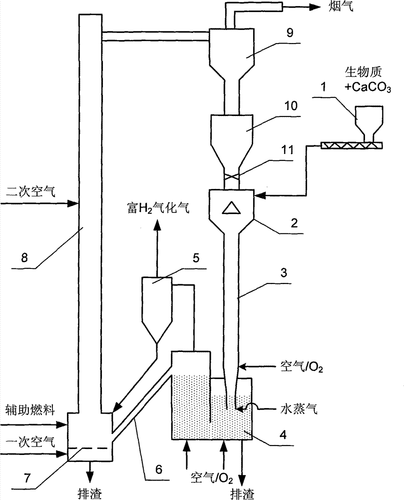
Fig. 1 is that embodiment of the invention circulating fluidized bed gasification device is always schemed.
Fig. 2 is embodiment of the invention internal mixer structural representation.
Fig. 3 is embodiment of the invention pyrolysis chamber internal structure synoptic diagram.
Fig. 4 is embodiment of the invention vaporizer internal structure and cloth wind, slag-drip opening structural representation.
Description of reference numerals: 1-biomass feeder, 2-mixing tank, 3-pyrolysis chamber, 4-vaporizer, the 5-gas separating device that gasifies, the 6-revert pipe, the 7-grid distributor, 8-combustion chamber, 9-smoke separator, the 10-feed bin, 11-dish valve, 12-dish valve outlet port pipe, 13-biomass filling tube, 14-deflection cone, 15-deflection cone pillar stiffener, 16-pyrolysis chamber baffle plate, 17-barrier support, 18-vaporizer dividing plate.
The present invention will be further described below in conjunction with the drawings and specific embodiments.
As shown in Figure 1, apparatus of the present invention structure is: biomass feeder 1 is connected with mixing tank 2 by biomass filling tube 13, mixing tank 2 upper ends connect dish valve 11, the lower end connects pyrolysis chamber 3, pyrolysis chamber's 3 outlets arrange the convergent conical tube, most of cone is inserted vaporizer 4 right sides, and the setting of cone section start and cone end arrange respectively air/O
2With the water vapour intake, vaporizer 4 becomes the left and right sides that the bottom is communicated with through the central dividing plate isolation, and bottom, vaporizer 4 left and right sides all arranges air/O
2Intake, bottom, vaporizer 4 right sides also arranges slag-drip opening, vaporizer 4 left side top introduction pipes connect the upside of gasification gas separating device 5, middle and lower part, vaporizer 4 left side is connected with 8 bottoms, combustion chamber by revert pipe 6, gasification gas separating device 5 bottoms arrange the solid particulate feed bin, and stopping valve is installed in the feed bin bottom bottom the combustion chamber, is connected with the returning charge at intermittence to the combustion chamber 8,8 bottoms, combustion chamber arrange auxiliary fuel charging opening and primary air intake, and 8 middle and upper parts, combustion chamber arrange the secondary air intake.Combustion chamber 8 top exits connect smoke separator 9, and smoke separator 9 tops arrange the fume emission mouth, and smoke separator 9 bottoms arrange feed bin 10, and feed bin 10 bottoms connect dish valve 11.
Described dish valve 11 is communicated with mixing tank 2 by dish valve outlet port pipe 12, and this outlet pipe inserts mixing tank 2 cavitys, and insertion portion length is 1-1.5 times of the outlet pipe internal diameter, and is inside collapsed shape, can play the effect of water conservancy diversion solid thermal carriers.
As shown in Figure 2, described mixing tank 2 is comprised of the cylinder barrel shaped cavity on top and the conical cavity of bottom, the ratio of both height is 3-4:1, the upper end of this cavity is connected with dish valve outlet port pipe 12, the lower end is connected with pyrolysis chamber 3, at axial line arc conical surface particle deflection cone 14 is installed, deflection cone 14 supports by deflection cone pillar stiffener 15, the cambered surface radian of this arc conical surface is 45-60 °, between dish valve outlet port pipe 12 and deflection cone 14, biomass filling tube 13 is set, biomass filling tube 13 is 15-30 ° of angle with mixing tank 2 direction of axis line, and the projection of biomass filling tube 13 outlet ports will all be positioned on the deflection cone 14 and need near mixing tank 2 axial lines one side.Biomass filling tube 13 exit end are more close dish valve outlet port pipe 12 pipe ends in the axial direction, and away from deflection cone 14 cambered surfaces.
As shown in Figure 3, described pyrolysis chamber 3 is cylindrical tube, pyrolysis chamber 3 is arranged alternately the half elliptic baffle plate 16 that is 45-60 ° of angle and tilts upward with axial line along about the axial line both sides, described baffle plate 16 elliptical center places are fixed on the barrier support 17, baffle plate 16 upper limbs are near pyrolysis chamber's right cylinder inwall but do not come in contact, barrier support 17 placement locations overlap with pyrolysis chamber's axial line, according to pyrolysis chamber's 3 internal diameters and biological particles size, each baffle spacing 0.3-0.6m, baffle plate number 5-10 piece.3 exits, pyrolysis chamber are transitioned into the slightly little cylindrical tube of diameter by back taper reducing cone, and this cylindrical tube inserts vaporizer 4 right sides, and intubating length is about between the 1/3-1/2 of vaporizer right side height.As shown in Figure 4,4 air/O are set on the cross section at cone upper limb place
2Intake, small-diameter circular cylindricality cylindrical shell lower edge arranges 4 water vapour intakes, described air/O on the cross section
2Intake, water vapour intake are symmetric at four semi-cardinal pointss that lay respectively at cross section of living in.
Described vaporizer 4 is the cuboid bubbling reactor that a bottom is communicated with, top is vaporized chamber dividing plate isolation, i.e. vaporizer left side, right side two portions.Dividing plate is positioned at the middle of rectangular parallelepiped vaporizer 4, and the dividing plate height is the 2/3-4/5 of vaporizer right side height.The right side vaporizer links to each other with pyrolysis chamber's outlet, and vaporizer bottom in right side arranges 1 slag-drip opening and 1 air/O
2Intake.Vaporizer top, described left side connects the gasification gas separating device, and the about vaporizer height in the left side of left side vaporizer 4/5 place arranges the solid particulate outlet, is connected with 8 bottoms, combustion chamber by revert pipe 6, and vaporizer bottom in left side also is provided with 1 air/O
2Intake, this vaporized chemical has the effect of fluidization air concurrently.
Described gasification gas separating device 5 bottoms connect stopping valve, 8 connections at the bottom of the stopping valve connection outlet Guan Bingyu combustion chamber, and gasification gas separating device 5 tops arrange syngas outlet.
8 bottoms, described combustion chamber arrange auxiliary fuel charging opening and primary air intake, and the about 1/2-2/3 At The Height in 8 middle and upper parts, combustion chamber arranges the secondary air intake.Combustion chamber 8 top exits connect smoke separator 9.Low tar hydrogen-rich synthetic gas technique is produced in one one kinds of wood chip circulating fluidized bed gasifications of embodiment
Use device shown in Figure 1, get the wood raw material of wood-working factory, the technical analysis of wood chip and ultimate analysis are shown in subordinate list 1, wood chip mixes through biomass feeder 1 in the ratio of 95:5 with sorbent material delivers to mixing tank 2 by biomass filling tube 13, with temperature be 850 ℃ thermal barrier, sorbent material (thermal barrier is 7:3 with the adsorbent mass ratio) is mixed heat transfer rapidly, change circulation ratio by the aperture of adjusting dish valve 11, wood chip is heated to about 600 ℃, wood chip subsequently, thermal barrier, sorbent material relies on action of gravitation to accelerate to enter pyrolysis chamber 3, through pyrolysis chamber's baffle plate 16 stop and to be decelerated to convergence static, experience the working cycle of continuous acceleration-deceleration, increase the residence time of wood chip in pyrolysis chamber 3 fully to separate out fugitive constituent.The semicoke that obtains after pyrolysis is complete, fugitive constituent move to 3 exits, pyrolysis chamber with thermal barrier, sorbent material etc., and introduce O at gasification agent inlet this moment
2, back taper throat structure has herein dwindled reaction volume, can promote volume to reduce reaction such as C and O
2, CO and O
2Between gasification reaction, the gasification agent inlet in reducing section exit passes into water vapour, O
2Introducing amount control equivalence ratio 0.15, water vapour/biomass mass ratio is 0.4.
Described sorbent material is selected from Wingdale, rhombspar or the peridotites a kind of, and described vaporized chemical is selected from air, O
2, in the water vapour one or both, described thermal barrier is quartz sand or river sand; The mass ratio about 30% of sorbent material and thermal barrier, the sorbent material continuous-feeding accounts for the 3-10% of total feeding coal.
Ratio in vaporizer 4 left and right sides bottoms in 4: 6 or 5: 5 passes into respectively O
2, the O of this two place
2Total introducing amount control equivalence ratio is 0.11.Sorbent material, semicoke continue herein performing catalytic pyrolysis on tar, simultaneously the sorbent material CO absorption occur
2, the reaction of semicoke oxygen enrichment-steam gasification.750 ℃ of gasification reaction temperature, gaseous products is drawn after gasification gas separating device 5 separates for subsequent use by vaporizer 4 left side top.Solid phase particles such as sorbent material, thermal barrier, flying dust, the complete semicoke of unreacted run to 8 bottoms, combustion chamber through revert pipe 6.
With the auxiliary fuel feed in the combustion chamber 8 bottoms, and burn with so far unreacted semicoke of circulation, liberated heat is with heating cycle thermal barrier and sorbent material, and the high-temperature calcination sorbent material, discharges CO
2The time recover the porous catalytic surface, auxiliary fuel can be coal or biomass, its feeding quantity is decided on furnace temperature, combustion chamber concentrated phase area temperature remains on 900 ℃.8 tops, combustion chamber pass into secondary air with further after-flame carbon residue, and combustion product gases obtains the circulation of thermal barrier and reproducing adsorbent sustainable participation next round after smoke separator 9 separates, and is rich in CO
2The flue gas of gas discharges by tail gas funnel.Flue gas can be used to dry biomass fuel, and making reinforced front biomass water content is about 10%.
In this embodiment, the gasification gas main component of acquisition is hydrogen, methane, carbon monoxide, carbonic acid gas, ethane, ethene, acetylene, propane, propylene, propine etc.By analysis, chief component and the physical property of gasification gas are as shown in table 2, and table 2 gives certain gasification process gained gasification gas and forms and physical property simultaneously, by as seen from Table 2, adopt gasify H in the synthetic gas that obtains of apparatus of the present invention
2Content is 44.5%, and more traditional gasification mode has improved 86.19%; Tar content is 0.189g/Nm
3, the tradition gasification has reduced by 88.14%; H
2/ CO ratio is 1.36, can be used as the unstripped gas of biomass-based liquid fuel technique.
The technical analysis of table 1 wood chip and ultimate analysis
Table 2 present embodiment and traditional gasification mode gasification result are relatively