The controlling method of concrete pumping structure and concrete pumping structure
Technical field
The present invention relates to carry the cylinder field with the fluid of piston, in particular to a kind of concrete pumping structure and controlling method thereof.
Background technique
In concrete conveying equipment, the concrete piston that contacts with concrete belongs to easily damaged parts, needs often to change.Two concrete pistons one in front and one in back to-and-fro motion in carrying cylinder during concrete conveying equipment work, to realize concrete continuous conveying, when needs are changed the concrete piston, it must be returned to carry cylinder and drive the water tank that oil cylinder is connected in can carry out demolition and replacement.Therefore, the concrete conveying equipment structure Design need consider that the concrete piston is convenient to the problem of dismantling and assembling.
In the available coagulation soil conveying equipment, it all is once to withdraw from a piston that the concrete piston withdraws from, and its typical structure has following three kinds:
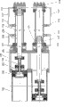
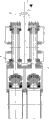
First kind, this structure is that the concrete piston is connected on the oil cylinder piston bar by middle brace rod, and middle brace rod can be connected by bolt with concrete piston and oil cylinder piston bar, also can connect (as Fig. 1, shown in 2) by cutting ferrule.This structure comprises carries cylinder 101, concrete piston assembly 102, concrete piston adpting flange 103, middle brace rod 104, water tank 105, a left side drives oil cylinder piston bar 106, (the pumping cylinder structure of top during wherein " left side " namely refers to illustrate) left side drives cylinder rod chamber hydraulic fluid port 107, a left side drives cylinder rod chamber 108, a left side drives cylinder rod chamber repairing pipe 109, a left side drives cylinder tube 110, a left side drives oil cylinder rodless cavity repairing pipe 111, a left side drives oil cylinder piston 112, a left side drives oil cylinder rodless cavity hydraulic fluid port 113, the right oil cylinder rodless cavity hydraulic fluid port 114 that drives, the right oil cylinder rodless cavity repairing pipe 115 that drives, the right oil cylinder rodless cavity 116 that drives, the right cylinder rod chamber repairing pipe 117 that drives, the right oil cylinder piston 118 that drives, the right cylinder rod chamber 119 that drives, the right cylinder rod chamber hydraulic fluid port 120 that drives.Fig. 1, method and step that pumping mechanism shown in 2 is changed concrete piston assembly 102 are as follows: when a needs dismounting left side drives oil cylinder concrete piston, the pressure oil of hydraulic system drives cylinder rod chamber hydraulic fluid port 107 and enters left side driving cylinder rod chamber 108 from a left side, thereby promoting left side driving oil cylinder piston 112 retreats with the left oil cylinder piston bar 106 that drives, the oil that a left side drives oil cylinder enters right driving oil cylinder rodless cavity 116 through left side driving oil cylinder rodless cavity hydraulic fluid port 113 and the right oil cylinder rodless cavity hydraulic fluid port 114 that drives, thereby promoting the right oil cylinder piston 118 that drives advances, when a left side drive oil cylinder to the end after, middle brace rod 104 just enters water tank 105.At this moment can pull down middle brace rod 104, operation left side driving oil cylinder moves ahead left side driving oil cylinder piston bar 106 again, allow it contact with concrete piston adpting flange, with bolt left side driving oil cylinder piston bar 106 and concrete piston adpting flange are linked up then, operation left side driving oil cylinder retreats again, thereby concrete piston assembly 102 is retracted in the water tank, so just can changes (as shown in Figure 2) to concrete piston assembly 102.After finishing, replacing by opposite order the concrete piston is recovered again.Also operate once in this order if change another concrete piston.Different is that the right oil cylinder concrete piston that drives of operation retreats.This structure once can only be changed a concrete piston, and operates and waste time and energy, and efficient is low.
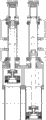
Second kind, shown in Fig. 3,4, this structure is compared replacing and the maintenance that first kind of structure realizes the concrete piston more easily, this structure mainly is by install a setting sleeve additional in the water tank of carrying between cylinder and the driving oil cylinder, under normal circumstances setting sleeve is contained in the water tank all the time, just run into setting sleeve when the concrete piston retreats like this, can not retreated in the water tank by setting sleeve location concrete piston.Only need setting sleeve is pulled down in water tank when changing the concrete piston, the piston rod of oil cylinder just can withdraw from the distance of a setting sleeve length more in water tank like this, and the concrete piston just can fall back in the water tank, can conveniently change the concrete piston.This structure is compared the replacing of the first kind of easier realization concrete of structure piston, but still needs the people to dismantle setting sleeve earlier when changing at every turn, also can only once change a concrete piston simultaneously.
The third, shown in Fig. 5,6, this structure automaticity height, replacing and maintenance concrete piston are very convenient, only need press a button and just can fall back on piston on one side in the water tank automatically.This structure mainly is to realize by installing a locating oil cylinder additional in the back that drives oil cylinder, when normal operation in normal, be full of the cavity that hydraulic oil forms a sealing in the locating oil cylinder, at this moment the concrete piston can't return in the water tank owing to stopping of locating oil cylinder piston, when needs repair or replace the concrete piston, only needing to start a button takes back in the fuel tank that does not have pressure by the oil in the locating oil cylinder, will extrude the oil in the locating oil cylinder when at this moment the concrete piston retreats, thereby make the concrete piston withdraw from the distance of a locating oil cylinder stroke, the concrete piston just can fall back in the water tank more.This structure is compared preceding two kinds of structures, operates more simple and convenient.But the shortcoming of such scheme is once can only withdraw from a concrete piston.
In sum, concrete pumping structure and controlling method in the present technology, in the replacing that solves the concrete piston and maintenance, exist problems such as the not high and duplication of labour of efficient, change and release system pressure after killing engine after two concrete pistons need withdraw from one earlier, change then, restart motor and withdraw from another concrete piston and change, change once need open machine-operated machine each twice, needed time is long, influence the efficiency of construction of concrete pump, be necessary to be improved.Especially two concrete pistons time of using the same, the degree of wear is close, therefore if can change simultaneously then to have significant meaning for changing efficient.
Summary of the invention
Technical problem to be solved by this invention provides a kind of concrete pumping structure that can move back two concrete pistons simultaneously, moves back the concrete piston efficiency thereby improve.
Scheme provided by the invention is a kind of concrete pumping structure, comprise the first and second pumping cylinder structures, each pumping cylinder structure comprises the conveying cylinder, water tank, drive oil cylinder, be provided with the concrete piston assembly in the described conveying cylinder, and the piston rod of described driving oil cylinder drives described concrete piston assembly to-and-fro motion in described conveying cylinder when pumping is worked, described water tank is between described conveying cylinder and described driving oil cylinder, it is characterized in that: comprise also and move back the concrete hydraulic system that described two of the concrete HYDRAULIC CONTROL SYSTEM of moving back drive oil cylinder and drive two described concrete piston assemblies and return simultaneously in the described water tank when moving back concrete.Therefore, can realize moving back simultaneously two concrete pistons, significantly improve the efficient that the concrete piston is changed.Preferably, described two rodless cavity hydraulic fluid port oil returns simultaneously when moving back concrete that drive oil cylinder.Drive the oil return in the oil cylinder when having realized moving back concrete in simple mode like this.
Preferred each pumping cylinder structure also comprises limit structure, and described limit structure carries out the described concrete piston assembly of spacing restriction and returns water tank and remove the described concrete piston assembly of spacing permission and return water tank when moving back concrete when pumping is worked.
The described concrete hydraulic system of moving back comprises and moves back concrete valve group, at least one pressure oil-source, described described at least one pressure oil-source of concrete valve group control that moves back, when described limit structure is in the spacing state of releasing, by moving back the concrete pipeline to the rod chamber hydraulic fluid port while fuel feeding of two described driving oil cylinders, the oil return simultaneously of its rodless cavity hydraulic fluid port.Thereby, by just realizing moving back two concrete pistons simultaneously to the oil return simultaneously of its rodless cavity hydraulic fluid port of the rod chamber hydraulic fluid port fuel feeding that drives oil cylinder, significantly improved the efficient that the concrete piston is changed.
According to an improvement project of the present invention, described limit structure comprises and moves back the concrete auxiliary cylinders, the described concrete auxiliary cylinders of moving back is positioned at described driving oil cylinder tail end or inside, the described concrete valve group of moving back is moved back the oil-feed of concrete auxiliary cylinders and oil return by described auxiliary cylinders hydraulic fluid port control of moving back the concrete auxiliary cylinders is described, in normal pumping working state with remove between the spacing state and change.Described moving back in the concrete auxiliary cylinders is provided with piston, and described driving oil cylinder moves back the concrete bar being provided with towards a side of moving back the concrete auxiliary cylinders, moves back the concrete bar and the described piston that moves back the concrete auxiliary cylinders is realized spacing by described.
Comprise under the situation of moving back the concrete auxiliary cylinders at limit structure, if this moves back concrete valve group and only controls and move back the concrete pipeline, can consider that arranging one in addition to the auxiliary cylinders hydraulic fluid port that moves back the concrete auxiliary cylinders is similar to the control valve group that this moves back concrete valve group, it for example is the combination of selector valve and an one-way valve of a two-position four-way valve, at this moment, the actuator port of this selector valve is connected to the auxiliary cylinders hydraulic fluid port, the filler opening of this selector valve is connected to the oil outlet of one-way valve, and the filler opening of one-way valve is connected to pressure oil-source, and the oil outlet of this selector valve is connected to oil sump tank.Setting by such control valve group, can be so that move back auxiliary cylinders hydraulic fluid port oil-feed in work of concrete auxiliary cylinders, move back the back cavity of concrete auxiliary piston by the locked effect locking of one-way valve, and the oil return when moving back concrete of auxiliary cylinders hydraulic fluid port moves realization by moving back of driving oil cylinder piston and moves back concrete after the concrete masthead leans on.
Preferably described move back concrete pipeline and described auxiliary cylinders hydraulic fluid port all with move back concrete valve group and be connected.This moment, mode of execution can have a variety ofly, and for example this moves back concrete valve group and comprises at least one selector valve and at least one one-way valve.Thereby only realize when moving back concrete to the oil-feed of two rod chamber hydraulic fluid ports, in work then not from the oil return of rod chamber hydraulic fluid port.
The specific embodiment that move back concrete valve group this moment is: this moves back concrete valve group and comprises first one-way valve, first selector valve and second one-way valve; The oil outlet of described first one-way valve is connected to the described concrete pipeline that moves back, an actuator port of described first selector valve is connected to the filler opening of described first one-way valve, another actuator port is connected to two auxiliary cylinders hydraulic fluid ports, and the filler opening of described first selector valve is connected with the oil outlet of described second one-way valve and then the oil outlet that is connected to first pressure oil-source and first selector valve is connected to oil sump tank.Can't be from moving back the oil return of concrete pipeline thereby guaranteed in proper functioning by the locking effect of first one-way valve, guaranteed to realize moving back by the oil-feed of auxiliary cylinders hydraulic fluid port the proper functioning time back cavity locking of concrete auxiliary piston by second one-way valve.Guaranteed simultaneously when moving back concrete when moving back concrete, by the auxiliary cylinders hydraulic fluid port oil to be expelled to oil sump tank to moving back concrete pipeline fuel feeding.
Another replaceable specific embodiment that move back concrete valve group this moment is: the described concrete valve group of moving back comprises first Pilot operated check valve, first selector valve, second one-way valve and second selector valve; The oil outlet of described first Pilot operated check valve is connected to the described concrete pipeline that moves back, the filler opening of described first Pilot operated check valve and control port are connected to two actuator ports of second selector valve respectively, the return opening of second selector valve is connected to the actuator port that oil sump tank and its filler opening are connected to first selector valve, another actuator port of first selector valve is connected to described two auxiliary cylinders hydraulic fluid ports, and the filler opening of first selector valve is connected with the oil outlet of second one-way valve and then the return opening that is connected to first pressure oil-source and first selector valve is connected to oil sump tank.The effect of first one-way valve among first Pilot operated check valve and the last embodiment is identical basically, difference is, when moving back concrete, to moving back after concrete pipeline fuel feeding returns to two concrete pistons in the water tank, can be by the commutation of second selector valve, to the control port oiling of first hydraulic control valve, thus might be with the oily oil return of moving back in concrete pipeline and the driving cylinder rod chamber.Certainly, in the another one specific embodiment, can consider first one-way valve and second selector valve are integrated into a valve.
According to another improvement project of the present invention, described limit structure comprises the setting sleeve that is installed in the described water tank, and described setting sleeve can be return water tank and be removed when moving back concrete and allow described concrete piston assembly to return water tank in the described concrete piston assembly of work timing system.At this moment, this moves back concrete valve group and only controls and move back the concrete pipeline, according to a specific embodiment that moves back concrete valve group, this moment, for example this moved back the combination that concrete valve group is selector valve and an one-way valve of a two-position four-way valve, the actuator port of this selector valve is connected to the one-way valve filler opening, move back the concrete pipeline and be connected to the oil outlet of this one-way valve, and the filler opening of this selector valve is connected to pressure oil-source, and the oil outlet of this selector valve is connected to oil sump tank.Thereby only realize when moving back concrete to two rod chamber hydraulic fluid ports fuel feeding simultaneously, and in work because the locked effect of one-way valve also can not be by moving back the oil return of concrete pipeline.Another mode of execution that moves back concrete valve group is to move back concrete valve group to comprise one first one-way valve, first selector valve and second selector valve; The actuator port of this second selector valve is connected to the one-way valve filler opening, the oil outlet of this one-way valve is connected to the described concrete pipeline that moves back, and the oil outlet that the filler opening that the filler opening of described second selector valve is connected to the actuator port of described first selector valve and described first selector valve is connected to pressure oil-source and first selector valve and second selector valve all is connected to oil sump tank.Certainly, in the another one specific embodiment, can consider first one-way valve and second selector valve are integrated into a valve.
According to a preferred embodiment of the present invention, also comprise the second valve group, the rodless cavity hydraulic fluid port of described driving oil cylinder is by second valve group control oil return simultaneously when moving back concrete.By the second valve group is provided, provides utilize this second valve group to be implemented in when moving back concrete oil return simultaneously simultaneously and when the work oil-feed to drive the possibility of described driving oil cylinder.
According to a preferred embodiment of the present invention, the rod chamber of described driving oil cylinder communicates, and the rodless cavity hydraulic fluid port of described driving oil cylinder makes one of them rodless cavity hydraulic fluid port fuel feeding when the work by second valve group control, and another rodless cavity hydraulic fluid port oil return.Thereby can switch with the state that moves back concrete with the state of simple mode in work.In normal working, by the oil-feed of a rodless cavity hydraulic fluid port, communicate owing to drive the rod chamber of oil cylinder, another rodless cavity hydraulic fluid port oil return can realize that in two pumping cylinder structures carries out suction, and another is carried out material spray.Certainly, be connected simultaneously with the rod chamber hydraulic fluid port of described driving oil cylinder although move back the concrete pipeline this moment, moving back the concrete pipeline this moment but can't be to rod chamber hydraulic fluid port fuel feeding or from the oil return of rod chamber hydraulic fluid port.Certainly, can consider that also the rodless cavity that will drive oil cylinder communicates, and will drive the rod chamber hydraulic fluid port oiling in the rod chamber hydraulic fluid port of oil cylinder, and another rod chamber hydraulic fluid port oil return that one in two pumping cylinder structures is carried out suction, and another carries out material spray.This moment is in order to realize moving back concrete, can corresponding adjustment such scheme, for example, make move back the concrete pipeline when moving back concrete to described rod chamber hydraulic fluid port fuel feeding simultaneously, then neither also not oil return of oil-feed when work, and when moving back concrete, from the oil return of two rodless cavity hydraulic fluid ports.
According to a preferred embodiment of the present invention, the second valve group comprises the 3rd selector valve and drain charge relief valve.
According to a preferred embodiment of the present invention, described rodless cavity hydraulic fluid port is connected to two actuator ports of described the 3rd selector valve respectively, and the filler opening of described the 3rd selector valve is connected to second pressure oil-source.Preferably, a side of described overflow drain charge valve is connected between described the 3rd selector valve and second pressure oil-source, and opposite side is connected to oil sump tank.Preferably, described relief valve is plug-in type overflow unloading valve.Described plug-in type overflow unloading valve comprises the electrically-controlled valve of the switching of cartridge valve and control cartridge valve.Thereby when the situation of work, electrically-controlled valve can be controlled cartridge valve and close, and make relief valve use as common relief valve, and when moving back the situation of concrete, electrically-controlled valve can be controlled cartridge valve and often open, from the oil return of two rodless cavity hydraulic fluid ports to oil sump tank.
Described first pressure oil-source is accumulator or oil pump.Described second pressure oil-source is accumulator or oil pump.Also can consider other pressure oil-source.
Describedly move back that the concrete auxiliary cylinders can be connected described driving oil cylinder tail end or the described concrete auxiliary cylinders of moving back is embedded in described driving oil cylinder inside.Can realize the above-mentioned concrete miscellaneous function of moving back as long as move back the concrete auxiliary cylinders.
The described concrete auxiliary piston that moves back is limited to the working position by the blocked part of moving back the setting in the concrete auxiliary cylinders.This blocked part for example can be collar.
Preferably, described first selector valve, second selector valve can be the cartridge valve valve group that the moving valve of solenoid directional control valve or hydraulic pressure, the 3rd selector valve can be solenoid directional control valve, electro hydraulic valve or electromagnetic valve.Each selector valve by electric control reversing is provided can automatically controlled ground in working order and move back between the concrete state and switch, therefore, significantly improved the automaticity of moving back concrete.
The present invention also relates to the controlling method of corresponding a kind of concrete pumping structure simultaneously, comprise normal pumping work control and move back concrete control, it is characterized in that, describedly move back concrete control and comprise the steps: that a) concrete valve group is moved back in control, rod chamber hydraulic fluid port while fuel feeding to two described driving oil cylinders, b) the control second valve group makes the rodless cavity hydraulic fluid port oil return simultaneously of described driving oil cylinder; The piston rod that drives oil cylinder drives described two concrete piston assemblies and returns described water tank simultaneously.Preferably also be included in the step c) of the limit function of the releasing limit structure that carries out or carry out simultaneously before the step a).
In one embodiment, described limit structure comprises and moves back the concrete auxiliary cylinders, the described concrete auxiliary cylinders of moving back is positioned at described driving oil cylinder tail end or inside, describedly move back the described auxiliary cylinders hydraulic fluid port oil return of moving back the concrete auxiliary cylinders of concrete valve group control and realize described step, control the oil-feed of described auxiliary cylinders hydraulic fluid port and switch to the pumping working state.In another embodiment, described limit structure comprises the setting sleeve that is installed in the described water tank, realizes described step c) by described setting sleeve is removed before step a).
The present invention can realize moving back simultaneously two concrete pistons, has significantly improved and has moved back the concrete piston efficiency.Only need just can return to two disposable whiles of concrete piston in the water tank automatically by the next one corresponding to the control knob that moves back concrete valve group that moves back the concrete pipeline, make that replacing, the maintenance of concrete piston, conveying cylinder and driving cylinder seal are more efficient and convenient, save the time of changing the concrete piston greatly.
Description of drawings
The present invention will be further described below in conjunction with drawings and Examples:
Fig. 1,2 first kinds of showing prior art respectively move back the working state of concrete scheme and move back the concrete state;
Fig. 3,4 second kinds of showing prior art respectively move back the working state of concrete scheme and move back the concrete state;
Fig. 5,6 show prior art respectively the third move back the working state of concrete scheme and move back the concrete state;
Fig. 7 a shows first specific embodiment of concrete pumping structure of the present invention; Fig. 7 b shows corresponding hydraulic element enlarged view;
Fig. 8 a shows second specific embodiment of concrete pumping structure of the present invention; Fig. 8 b shows corresponding hydraulic element enlarged view;
Fig. 9 a shows the 3rd specific embodiment of concrete pumping structure of the present invention; Fig. 9 b shows corresponding hydraulic element enlarged view;
Figure 10,11 show the 4th, the 5th specific embodiment of concrete pumping structure of the present invention; Figure and Figure 10 c that Figure 10 a wherein, 10b are respectively working state and move back the concrete state show corresponding hydraulic element enlarged view; Figure 11 a, 11b are respectively the figure that moves back concrete state and working state, and Figure 11 c shows corresponding hydraulic element enlarged view;
Figure 12,13,14 show the 6th, the 7th, the 8th specific embodiment of concrete pumping structure of the present invention.Figure 12 b wherein, 13b, 14b show corresponding hydraulic element enlarged view;
Embodiment
Fig. 7 shows first specific embodiment of concrete pumping structure of the present invention, because the present invention is intended to solve the concrete problem of moving back, therefore only shows the figure that moves back under the concrete state.
Concrete pumping structure of the present invention comprises the first and second pumping cylinder structures, and the structure of two pumping cylinder structures is identical.A pumping cylinder structure in the pump structure (being arranged in the figure top) comprises conveying cylinder 1, concrete piston assembly 2, water tank 3, concrete piston adpting flange 4, clip 5, driving oil cylinder piston bar 6, drives oil cylinder 7, the rod chamber hydraulic fluid port 8 of driving oil cylinder, the rod chamber 9 that drives oil cylinder, repairing pipe 10, driving oil cylinder piston 11, moves back concrete auxiliary cylinders 12.Move back concrete auxiliary piston 13, auxiliary cylinders hydraulic fluid port 14, move back concrete bar 15, move back the blocked part 16 in the concrete auxiliary cylinders 12, the rodless cavity hydraulic fluid port 17 of driving oil cylinder.The constituent elements of another one pumping cylinder structure also marks with similar label, and different is to have marked symbol at each label ', therefore just do not do having marked in addition in the reference identification part.
The driving oil cylinder piston bar 6 that wherein drives in the oil cylinder 7 directly links together by concrete piston adpting flange 4 and clip 5 with carrying the concrete piston assembly 2 in the cylinder 1.Described driving oil cylinder 7 is by the control to-and-fro motion.Owing to present invention focuses on to move back the improvement of concrete aspect, therefore under normal circumstances how just no longer to be elaborated by concrete pump control device for reversing (not shown) control to-and-fro motion for driving oil cylinder 7.Wherein move back concrete auxiliary cylinders 12 and can be connected as shown in Figure 7 to drive oil cylinder 7 afterbodys or embed and drive oil cylinder inside, move back concrete auxiliary piston 13 by auxiliary cylinders hydraulic fluid port 14, a 14 ' oil-feed or oil return and in moving back concrete auxiliary cylinders 12 telescopically move; Drive oil cylinder piston 11 and move back concrete bar 15 being provided with towards a side of moving back concrete auxiliary cylinders 12.
That is to say, in first, second, third specific embodiment, move back concrete auxiliary cylinders 12 and the concrete auxiliary piston 13 that moves back that wherein arranges has constituted and limits water tank 3 is return in described concrete piston assembly 2 when work limit structure.Described move back to be provided with in the concrete auxiliary cylinders 12 movably move back concrete auxiliary piston 13, the described concrete auxiliary piston 13 that moves back is by an auxiliary cylinders hydraulic fluid port 14,14 ' oil-feed is spacing to carry out when working, limiting described concrete piston assembly 2, to return water tank 3 or oil return spacing to remove when moving back concrete, allows described concrete piston assembly 2 to return water tank 3.Move back concrete bar 15 and the described concrete auxiliary piston 13 of moving back is realized spacingly by described, wherein move back concrete bar 15 and be connected and drive on the oil cylinder piston 11, when work, move back concrete auxiliary piston 13 and carry out spacing by leaning.
In the present invention, also comprise and move back the concrete hydraulic system, the described concrete hydraulic system of moving back comprises and moves back concrete valve group 30, at least one pressure oil- source 21,23, described described at least one pressure oil-source of concrete valve group control that moves back, when described limit structure is in the spacing state of releasing, by moving back the concrete pipeline to the rod chamber hydraulic fluid port while fuel feeding of two described driving oil cylinders, the oil return simultaneously of its rodless cavity hydraulic fluid port, described two of the concrete HYDRAULIC CONTROL SYSTEM of moving back drive oil cylinder 7,7 ' and then drive two described concrete piston assemblies 2 and return simultaneously in the described water tank 3 when moving back concrete.Move back concrete pipeline 18 and so controllably connect with the rod chamber hydraulic fluid port 8,8 ' that drives oil cylinder 7,7 ', namely move back concrete pipeline 18 when moving back concrete to 8,8 ' while of rod chamber hydraulic fluid port fuel feeding.So just concrete piston assembly 2,2 ' can be returned to simultaneously and carry out repair and replacement in the water tank, also can change simultaneously and carry cylinder and drive cylinder seal.Meanwhile, drive rodless cavity hydraulic fluid port 17,17 ' oil return simultaneously when moving back concrete of oil cylinder 7,7 '.
In this embodiment, move back concrete pipeline 18 when moving back concrete to rod chamber hydraulic fluid port 8,8 ' fuel feeding simultaneously, when normal working, then do not move back the oil return of concrete pipeline by this.This move back concrete valve group 30 comprise first Pilot operated check valve 24 ', the first selector valve DT1, second one-way valve 25 and the second selector valve DT2; First Pilot operated check valve 24 ' oil outlet be connected to and move back concrete pipeline 18, first Pilot operated check valve 24 ' filler opening and control port two actuator ports being connected to the second selector valve DT2 respectively, the return opening of the second selector valve DT2 is connected to the actuator port that oil sump tank 22 and its filler opening are connected to the first selector valve DT1, another actuator port of the first selector valve DT1 is connected to two auxiliary cylinders hydraulic fluid ports 14, the filler opening of 14 ', the first selector valve DT1 is connected with the oil outlet of second one-way valve 25 and then the return opening that is connected to first pressure oil-source 21 and the first selector valve DT1 is connected to oil sump tank 22.First pressure oil-source 21 is accumulator, can certainly be other pressure oil-sources such as oil pump.
This first selector valve DT1, the second selector valve DT2 is the electromagnetism two-position four-way valve in this embodiment.
In the time of in working order, the first selector valve DT1 is connected to auxiliary cylinders hydraulic fluid port 14,14 ' pipeline 20,20 ' actuator port is connected with the filler opening of the first selector valve DT1, and that actuator port that the filler opening with the second selector valve DT2 of the first selector valve DT1 is connected then is connected with the oil outlet of the first selector valve DT1.
When moving back the concrete state, the first selector valve DT1 is connected to auxiliary cylinders hydraulic fluid port 14,14 ' pipeline 20,20 ' actuator port is connected with the oil outlet of the first selector valve DT1, and that actuator port that the filler opening with the second selector valve DT2 of the first selector valve DT1 is connected then is connected with the filler opening of the first selector valve DT1.
In the time of in working order, that working hole that the filler opening with first one-way valve 24 of the second selector valve DT2 is connected is connected with the oil outlet of the second selector valve DT2, and that working hole that the control port with first one-way valve 24 of the second selector valve DT2 is connected is connected with the filler opening of the second selector valve DT2.
When moving back the concrete state, that working hole that the filler opening with first one-way valve 24 of the second selector valve DT2 is connected is connected with the filler opening of the second selector valve DT2, and that working hole that the control port with first one-way valve 24 of the second selector valve DT2 is connected is connected with the oil outlet of the second selector valve DT2.
Having guaranteed in proper functioning by the locking effect of first one-way valve 24 can't be from moving back 18 oil returns of concrete pipeline, can be to moving back 18 oil-feeds of concrete pipeline when moving back concrete.Guaranteed to realize moving back by the oil-feed of auxiliary cylinders hydraulic fluid port the proper functioning time back cavity locking of concrete auxiliary piston 13 simultaneously by second one-way valve 25, to be full of pressure oil in this back cavity, pressure oil then can not reflux owing to second one-way valve 25, thereby will move back concrete auxiliary piston 13 and be locked in blocked part 16, drive oil cylinder 7 when being provided at proper functioning, position limitation protection when the possible commutation controlling mechanism that for example drives oil cylinder piston 11 under the situation that 7 ' stroke lengthens breaks down, prevent that concrete piston assembly 2,2 ' from returning in the water tank 3 when proper functioning.When moving back concrete, by auxiliary cylinders hydraulic fluid port 14,14 ' oil is expelled to oil sump tank, moves after the concrete masthead leans on and realize moving back concrete by driving moving back of oil cylinder piston 6,6 '.
Drive the rodless cavity hydraulic fluid port 17,17 ' of oil cylinder 7,7 ' by second valve group control oil return simultaneously when moving back concrete.The second valve group comprises the 3rd selector valve DT3 and overflow drain charge valve 27.Rodless cavity hydraulic fluid port 17,17 ' is connected to two actuator ports of the 3rd selector valve DT3 respectively, and the filler opening of the 3rd selector valve is connected to second pressure oil-source 23.One side of overflow drain charge valve 27 is connected between the 3rd selector valve DT3 and second pressure oil-source 23, and opposite side is connected to oil sump tank 22.Second pressure oil-source 23 is accumulator or oil pump.
In this embodiment, drive the rod chamber 9 of oil cylinder 7,7 ', 9 ' communicates, and drives the rodless cavity hydraulic fluid port 17 of oil cylinder 7,7 ', 17 ' one of them rodless cavity hydraulic fluid port fuel feeding when making in working order by 27 controls of the 3rd selector valve DT3 and relief valve, and another rodless cavity hydraulic fluid port oil return.When moving back the concrete state, then two rodless cavity hydraulic fluid port 17,17 ' oil returns.As shown in the figure, in the time of in working order, when control valve DT4 gets when electric, cartridge valve is closed, and overflow drain charge valve 27 uses as relief valve usually, has only when system pressure surpasses preset pressure, and cartridge valve is opened the relief valve overflow.When moving back the concrete state, namely control valve DT4 must not when electricity, and cartridge valve is often opened, and hydraulic system is directly rushed down lotus.Therefore, two rodless cavity hydraulic fluid port 17,17 ' all oil returns.Thereby can switch with the state that moves back concrete with the state of simple mode in work.
Furthermore, in normal working, by the oil-feed of a rodless cavity hydraulic fluid port, because drive the rod chamber 9 of oil cylinder 7,7 ', 9 ' communicates, another rodless cavity hydraulic fluid port oil return can realize that in two pumping cylinder structures carries out suction, and another is carried out material spray.Certainly, connect simultaneously with the rod chamber hydraulic fluid port 8,8 ' that drives oil cylinder 7,7 ' although move back concrete pipeline 18 this moment, moving back the concrete pipeline 18 this moments but can't be to rod chamber hydraulic fluid port fuel feeding or from the oil return of rod chamber hydraulic fluid port.Therefore, moving back the concrete pipeline does not exert an influence for normal pumping process.Certainly, can consider that also the rodless cavity that will drive oil cylinder communicates, and will drive the rod chamber hydraulic fluid port oiling in the rod chamber hydraulic fluid port of oil cylinder, and another rod chamber hydraulic fluid port oil return, realize proper functioning, this moment is in order to realize moving back concrete, can corresponding adjustment such scheme, for example, make move back the concrete pipeline when moving back concrete to rod chamber hydraulic fluid port fuel feeding simultaneously, then neither also not oil return of oil-feed when work, and in oil return, from the oil return of two rodless cavity hydraulic fluid ports.
The 3rd selector valve DT3 in the second valve group can determine in the time of proper functioning, which rodless cavity hydraulic fluid port oil-feed, and corresponding another rodless cavity hydraulic fluid port oil return.
The above-mentioned concrete pumping structure operating process that can realize that two concrete pistons withdraw from simultaneously is as follows: in the time will withdrawing from two concrete pistons simultaneously, hydraulic oil drives oil cylinder 7 from two, 7 ' rod chamber hydraulic fluid port 8,8 ' oil-feed simultaneously, two drive oil cylinder 7 simultaneously, 7 ' rodless cavity is all received in the stress-free fuel tank, with two move back concrete auxiliary cylinders 12,12 ' auxiliary cylinders hydraulic fluid port 14,14 ' also receives fuel tank, at this moment two driving oil cylinder pistons and piston rod are drawn back under the effect of oil pressure simultaneously, piston rod can withstand to move back and move back the concrete auxiliary piston in the concrete auxiliary cylinders, the two concrete plugs that link to each other with two driving oil cylinder piston bars just are retracted in the water tank from carrying in the cylinder simultaneously like this, so just can be to two concrete pistons, two carry the cylinder sealing to change.
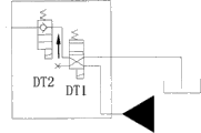
Fig. 8 shows second specific embodiment of concrete pumping structure of the present invention.It is different that the place different with first specific embodiment only is to move back the design of concrete valve group 30.This moves back concrete valve group 30 and comprises first one-way valve 24, the first selector valve DT1 and second one-way valve 25; The oil outlet of first one-way valve 24 is connected to and moves back concrete pipeline 18, the actuator port of the first selector valve DT1 is connected to the filler opening of first one-way valve 24, another actuator port is connected to two auxiliary cylinders hydraulic fluid ports 14, the filler opening of 14 ', the first selector valve DT1 is connected with the oil outlet of second one-way valve 25 and then the DT1 oil outlet that is connected to first pressure oil-source 21 and first selector valve is connected to oil sump tank 22.
In the time of in working order, the first selector valve DT1 is connected to auxiliary cylinders hydraulic fluid port 14,14 ' pipeline 20,20 ' actuator port is connected with the filler opening of the first selector valve DT1, and that actuator port that the filler opening with first one-way valve 24 of the first selector valve DT1 is connected then is connected with the oil outlet of the first selector valve DT1.
When moving back the concrete state, the first selector valve DT1 is connected to auxiliary cylinders hydraulic fluid port 14,14 ' pipeline 20,20 ' actuator port is connected with the oil outlet of the first selector valve DT1, and that actuator port that the filler opening with first one-way valve 24 of the first selector valve DT1 is connected then is connected with the filler opening of the first selector valve DT1.
First Pilot operated check valve 24 among Fig. 7 ' and Fig. 8 in the difference of first one-way valve be, when moving back concrete, to moving back after concrete pipeline fuel feeding returns to two concrete pistons in the water tank, can be by the commutation of the second selector valve DT2, to the control port oiling of first hydraulic control valve, thus might be with the oily oil return of moving back in the concrete pipeline.
Fig. 9 shows the 3rd specific embodiment of concrete pumping structure of the present invention.The places different with second specific embodiment are, have saved the second valve group, but directly rodless cavity hydraulic fluid port 17,17 ' are passed through pipeline 19, and 19 ' is connected to oil sump tank.Thereby be independent of the control gear that the driving oil cylinder is back and forth driven and realize moving back the concrete function.
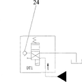
The control that all will move back concrete pipeline 18 and auxiliary cylinders hydraulic fluid port 14,14 ' among above-mentioned each embodiment is integrated in same moving back in the concrete valve group.Alternatively, also can carry out the control branch that moves back concrete pipeline 18 and auxiliary cylinders hydraulic fluid port 14,14 ' is come.For example move back concrete pipeline 18 and move back concrete valve group 30 and be connected.Move back concrete valve group 30 and comprise a selector valve and an one-way valve, the actuator port of this selector valve is connected to the one-way valve filler opening, the oil outlet of this one-way valve is connected to and moves back concrete pipeline 18, and the filler opening of selector valve is connected to pressure oil-source and its oil outlet is connected to oil sump tank.And correspondingly can consider that arranging one in addition to the auxiliary cylinders hydraulic fluid port that moves back the concrete auxiliary cylinders is similar to the control valve group that this moves back concrete valve group, it for example is the combination of selector valve and an one-way valve of a two-position four-way valve, at this moment, the actuator port of this selector valve is connected to the auxiliary cylinders hydraulic fluid port, the filler opening of this selector valve is connected to the oil outlet of one-way valve, and the filler opening of one-way valve is connected to pressure oil-source, and the oil outlet of this selector valve is connected to oil sump tank.
Figure 10,11 show the 4th, the 5th specific embodiment of concrete pumping structure of the present invention.Be provided with among Figure 10 and lead to the rod chamber hydraulic fluid port 8 that each drives oil cylinder respectively, two of 8 ' are moved back concrete pipeline 18, the design of concrete valve group is moved back in corresponding adjustment this moment, and the quantity of first one-way valve 24 is set to two, as the working state figure of Figure 10 a and moving back shown in the concrete phase diagram as Figure 10 b.Be provided with among Figure 11 and lead to the rod chamber hydraulic fluid port 8 that drives oil cylinder respectively, one of 8 ' is moved back concrete pipeline 18, in this embodiment, move back that concrete valve group has comprised first one-way valve integrated and a two position two-way valve DT2 of the function of second selector valve and the first selector valve DT1 and second one-way valve 25 that is designed to two-position four-way valve, as Figure 11 a move back the concrete phase diagram and shown in the working state figure of Figure 11 b.
Figure 12,13,14 show the 6th, the 7th, the 8th specific embodiment of concrete pumping structure of the present invention.Wherein, limit structure adopts setting sleeve, move back the goal of the invention of two concrete pistons at this moment for time in realizing according to the present invention, can at first each setting sleeve be removed, drive rod chamber hydraulic fluid port 8,8 ' the while fuel feeding of oil cylinder via moving back concrete pipeline 18 to each by moving back concrete valve group then.In these embodiments, the second valve group is not set this moment.In the embodiment of Figure 12, move back concrete valve group and comprise first one-way valve 24 and the first selector valve DT1, the filler opening of this first one-way valve 24 is connected to the actuator port of the described first selector valve DT1, the filler opening of the first selector valve DT1 is connected to pressure oil-source, and oil outlet is connected to oil sump tank.In the embodiment in Figure 13, move back concrete valve group comprise first Pilot operated check valve 24 ', the second selector valve DT2 and the first selector valve DT1, the filler opening of first one-way valve 24 is connected to the actuator port of the second selector valve DT2, the filler opening of the described second selector valve DT2 is connected to the actuator port of the first selector valve DT1 and oil outlet is connected to oil sump tank, and the filler opening of the first selector valve DT1 is connected to pressure oil-source and oil outlet is connected to oil sump tank.In the embodiment in Figure 14, move back that concrete valve group has comprised first one-way valve integrated and a two position two-way valve DT2 of the function of second selector valve and the first selector valve DT1 that is designed to two-position four-way valve.
Reference identification
1 carries cylinder 2 concrete piston assemblies
3 water tanks, 4 concrete piston adpting flanges
5 clips 6 drive the oil cylinder piston bar
7,7 ' drives oil cylinder 8,8 ' rod chamber hydraulic fluid port
9 rod chambers, 10 repairing pipes
11 drive oil cylinder piston 12 moves back the concrete auxiliary cylinders
13 move back concrete auxiliary piston 14,14 ' auxiliary cylinders hydraulic fluid port
15 move back concrete bar 16 blocked parts
17,17 ' rodless cavity hydraulic fluid port 18 moves back the concrete pipeline
19 pipelines, 20 pipelines
21 first pressure oil-sources, 22 oil sump tanks
23 second pressure oil-sources, 24 first one-way valves
25 second one-way valves, 27 overflow drain charge valves
30 move back concrete valve group 24 ' first Pilot operated check valve