CN201391494Y - Hydraulic device for automatic high/low pressure switching and unidirectional expansion of double main pumping cylinders of concrete pump truck - Google Patents
Hydraulic device for automatic high/low pressure switching and unidirectional expansion of double main pumping cylinders of concrete pump truck Download PDFInfo
- Publication number
- CN201391494Y CN201391494Y CN200920172782U CN200920172782U CN201391494Y CN 201391494 Y CN201391494 Y CN 201391494Y CN 200920172782 U CN200920172782 U CN 200920172782U CN 200920172782 U CN200920172782 U CN 200920172782U CN 201391494 Y CN201391494 Y CN 201391494Y
- Authority
- CN
- China
- Prior art keywords
- cover
- plate type
- valve
- type cartridge
- cartridge valve
- Prior art date
- Legal status (The legal status is an assumption and is not a legal conclusion. Google has not performed a legal analysis and makes no representation as to the accuracy of the status listed.)
- Expired - Lifetime
Links
Images
Abstract
The utility model relates to a hydraulic device for automatic high/low pressure switching and unidirectional expansion of double main pumping cylinders of a concrete pump truck. The hydraulic device is characterized in that an assistant valve block having an oil path therein and a corresponding interface is additionally arranged on the oil path between a main valve block and a main cylinder I and between the main valve block and a main cylinder II, i.e. a main hydraulic pipe I and a main hydraulic pipe II; two two-position four-way solenoid directional valves and six screw-in cartridge valves are additionally arranged on the assistant valve block; the two two-position four-way solenoid directional valves and the six screw-in cartridge valves are correspondingly connected through oil paths; and the six screw-in cartridge valves are correspondingly connected with the main cylinder I, the main cylinder II and the main hydraulic paths through oil paths. The on/off state of the six screw-in cartridge valves can be controlled by switching the two two-position four-way solenoid directional valves so as to achieve unidirectional expansion and automatic high/low pressure switching of the double main pumping cylinders. The hydraulic device has the advantages of reasonable structure, convenient operation, non-stop switching, no leakage and convenient check, and reduces time and effort consumption in replacing concrete piston.
Description
Technical field
The utility model belongs to hydraulic pressure installation, relates in particular to a kind of pumps hydraulic device of concrete mixer.
Background technique
At present, the concrete pump truck pumping hydraulic system is typically equipped with high-low voltage switching device, but it is high, switching between the low pressure pumping is realized by the hand operating mechanism hydraulic valve block, promptly pull down the screw on the hydraulic valve block, rotary machine switches cover plate, finish height, switch between the low pressure pumping, this device is when switching, on the one hand that main frame is flame-out, length consuming time on the other hand, and also have hydraulic oil to drop down from junction plane, if pressure has not been let out, also easily the sealing O shape of junction plane circle is damaged, can't realize also that in addition two master cylinders of pumps hydraulic system are flexible in the same way, this debugging and concrete piston to the pumps hydraulic system is checked and the concrete piston, the pumping master cylinder, the replacing of concrete cylinder brings great inconvenience.
Summary of the invention
The purpose of this utility model provides that the automatic high low pressure of the two master cylinders of a kind of concrete pump truck pumping switches and telescoping hydraulic device in the same way, can easily switch between pumping system low pressure, high pressure conditions, need not stop main frame, and the time is short, and system does not have any leakage; The concrete mixer master cylinder is flexible in the same way, can check or change concrete piston, saving of work and time easily; Make that simultaneously whole hydraulic system is more perfect, need of work is satisfied in hommization better.
The purpose of this utility model is achieved like this: the automatic high low pressure of the two master cylinders of a kind of concrete pump truck pumping switches and telescoping hydraulic device in the same way, by in hydraulic system, setting up two two four-way electromagnetic reversing valves, six cover-plate type cartridge valves, by two two four-way electromagnetic reversing valves, dead electricity, and then control the keying state of six cover-plate type cartridge valves, realize two master cylinders of pumps hydraulic system flexible in the same way and automatically high low pressure switch.
The automatic high low pressure of the two master cylinders of a kind of concrete pump truck pumping switches and telescoping hydraulic device in the same way, mainly by hydraulic oil container, main oil pump, the main valve piece, main hydraulic pipe line I, main hydraulic pipe line II, master cylinder I, master cylinder II and return filter are formed, it is characterized in that: at main valve piece and master cylinder I, on the oil circuit between the master cylinder II, promptly on main hydraulic pipe line I and main hydraulic pipe line II, set up inside and offer oil circuit and the corresponding secondary valve piece that interface is set, the board-like cartridge valve I of mounting cover successively from left to right at the middle part on secondary valve piece surface, cover-plate type cartridge valve II, cover-plate type cartridge valve III and cover-plate type cartridge valve IV, board-like cartridge valve V of mounting cover and cover-plate type cartridge valve VI successively from the bottom to top on the top on secondary valve piece surface install two four-way electromagnetic reversing valve I and two four-way electromagnetic reversing valve II respectively on the left side and the right side of the bottom on secondary valve piece surface; The control port of the A mouth of two four-way electromagnetic reversing valve I and cover-plate type cartridge valve I links to each other by the oil circuit of secondary valve piece inside, and the control port of the B mouth of two four-way electromagnetic reversing valve I and cover-plate type cartridge valve II, cover-plate type cartridge valve V links to each other by the oil circuit of secondary valve piece inside; The A mouth of two four-way electromagnetic reversing valve II and cover-plate type cartridge valve IV, the control port of cover-plate type cartridge valve VI links to each other by the oil circuit of secondary valve piece inside, the control port of the B mouth of two four-way electromagnetic reversing valve II and cover-plate type cartridge valve III links to each other by the oil circuit of secondary valve piece inside, the P mouth of two four-way electromagnetic reversing valve I and two four-way electromagnetic reversing valve II links to each other with main hydraulic pipe line II and system pressure hydraulic pipe line with main hydraulic pipe line I by one-way valve is corresponding respectively, returns hydraulic oil container after two four-way electromagnetic reversing valve I link to each other with the T mouth of two four-way electromagnetic reversing valve II; In secondary valve piece left side, the rod chamber of master cylinder I links to each other with the upside hydraulic fluid port of cover-plate type cartridge valve I and the left side hydraulic fluid port of cover-plate type cartridge valve V with hydraulic pipe line IV, the rodless cavity of master cylinder I links to each other with the upside hydraulic fluid port of cover-plate type cartridge valve III and the upside hydraulic fluid port of cover-plate type cartridge valve VI with hydraulic pipe line III, on secondary valve piece right side, the rod chamber of master cylinder II links to each other with the upside hydraulic fluid port of cover-plate type cartridge valve IV and the upside hydraulic fluid port of cover-plate type cartridge valve V with hydraulic pipe line VI, and the rodless cavity of master cylinder II links to each other with cover-plate type cartridge valve VI left side hydraulic fluid port with cover-plate type cartridge valve II upside hydraulic fluid port with hydraulic pipe line V; Main hydraulic pipe line I links to each other with the right side hydraulic fluid port of cover-plate type cartridge valve I and the left side hydraulic fluid port of cover-plate type cartridge valve II, and main hydraulic pipe line II links to each other with the right side hydraulic fluid port of cover-plate type cartridge valve III and the left side hydraulic fluid port of cover-plate type cartridge valve IV.
During work, when the electromagnet of two four-way electromagnetic reversing valve I and two four-way electromagnetic reversing valve II all must not electricity, cover-plate type cartridge valve I, cover-plate type cartridge valve IV and cover-plate type cartridge valve VI open, cover-plate type cartridge valve II, cover-plate type cartridge valve III, cover-plate type cartridge valve V closes, the pressure oil of system is successively through main hydraulic pipe line I, cover-plate type cartridge valve I, hydraulic pipe line IV enters the rod chamber of master cylinder I, the hydraulic oil of master cylinder I rodless cavity is successively through hydraulic pipe line III, cover-plate type cartridge valve VI, hydraulic pipe line V enters the rodless cavity of master cylinder II, the hydraulic oil of the rod chamber of master cylinder II is successively through hydraulic pipe line VI, cover-plate type cartridge valve IV, main hydraulic pipe line II flows back to fuel tank by main valve piece 3, and this kind state is called the low pressure pumping; When the electromagnet of two four-way electromagnetic reversing valve I and two four-way electromagnetic reversing valve II all gets when electric, cover-plate type cartridge valve II, cover-plate type cartridge valve III, cover-plate type cartridge valve V opens, cover-plate type cartridge valve I, cover-plate type cartridge valve IV, cover-plate type cartridge valve VI closes, the pressure oil of system is successively through main hydraulic pipe line I, cover-plate type cartridge valve II, hydraulic pipe line V enters the rodless cavity of master cylinder II, the hydraulic oil of master cylinder II rod chamber is through hydraulic pipe line VI, cover-plate type cartridge valve V, hydraulic pipe line IV enters the rod chamber of master cylinder I, the hydraulic oil of the rodless cavity of master cylinder I is successively through hydraulic pipe line III, cover-plate type cartridge valve III, main hydraulic pipe line II flows back to fuel tank by main valve piece 3, and this kind state is called the high pressure pumping; The high low pressure state of concrete pump truck pumping system: the rodless cavity of two master cylinders is communicated with, and rod chamber oil-feed, oil return are called the low pressure pumping; The rod chamber of two master cylinders is communicated with, and rodless cavity oil-feed, oil return are called the high pressure pumping; When two four-way electromagnetic reversing valve I get, two four-way electromagnetic reversing valve II must not, cover-plate type cartridge valve II, cover-plate type cartridge valve IV, cover-plate type cartridge valve V, cover-plate type cartridge valve VI open, cover-plate type cartridge valve I, cover-plate type cartridge valve III close, and pressure oil enters the rodless cavity of master cylinder I and master cylinder II successively simultaneously through main hydraulic pipe line I, cover-plate type cartridge valve II, cover-plate type cartridge valve VI; The hydraulic oil of the rod chamber of master cylinder I and master cylinder II flows back to hydraulic oil container through the main valve piece to reply again through hydraulic pipe line IV, cover-plate type cartridge valve V, hydraulic pipe line VI, cover-plate type cartridge valve IV and main hydraulic pipe line II, and master cylinder I and master cylinder II stretch out in the same way; Enter the rod chamber of master cylinder I and master cylinder II simultaneously through main hydraulic pipe line II, cover-plate type cartridge valve IV, cover-plate type cartridge valve V, hydraulic pipe line IV, hydraulic pipe line VI when the pressure oil correspondence, the hydraulic oil correspondence of the rodless cavity of master cylinder I and master cylinder II flows back to hydraulic oil container through hydraulic pipe line III, hydraulic pipe line V, cover-plate type cartridge valve VI, cover-plate type cartridge valve II and main hydraulic pipe line I through the main valve piece, and master cylinder I and master cylinder II withdraw in the same way; Operation main valve piece, main hydraulic pipe line I, main hydraulic pipe line II are alternately into and out of oil.
The automatic high low pressure of the two master cylinders of the concrete pump truck pumping that the utility model proposed switches and telescoping hydraulic device is rational in infrastructure in the same way, easy to operate, can between pumping system low pressure, high pressure conditions, easily switch, need not stop main frame, time is short, and system does not have any leakage; The concrete mixer master cylinder is flexible in the same way, can check, change concrete piston, saving of work and time easily; Make that in the same way whole hydraulic system is more perfect, need of work is satisfied in hommization better.
Below in conjunction with drawings and Examples the automatic high low pressure of the two master cylinders of the concrete pump truck pumping that the utility model proposes is switched and in the same way telescoping hydraulic device be described further.
Description of drawings
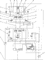
Fig. 1 is that the automatic high low pressure of the two master cylinders of the concrete pump truck pumping that proposes of the utility model switches and the hydraulic schematic diagram of telescoping hydraulic device in the same way.
Among Fig. 1: 1, hydraulic oil container 2, main oil pump 3, main valve piece 4, main hydraulic pipe line I5, secondary valve piece 6, master cylinder I 7, master cylinder II 8, main hydraulic pipe line II 9, two four-way electromagnetic reversing valve I 10, two four-way electromagnetic reversing valve II 11, cover-plate type cartridge valve I 12, cover-plate type cartridge valve II 13, cover-plate type cartridge valve III 14, cover-plate type cartridge valve IV 15, cover-plate type cartridge valve V 16, cover-plate type cartridge valve VI 17, hydraulic pipe line III18, hydraulic pipe line IV 19, hydraulic pipe line V 20, hydraulic pipe line VI 21, return filter
Embodiment
As can be seen from Figure 1: the automatic high low pressure of the two master cylinders of a kind of concrete pump truck pumping switches and telescoping hydraulic device in the same way, mainly by hydraulic oil container 1, main oil pump 2, main valve piece 3, main hydraulic pipe line I 4, main hydraulic pipe line II 8, master cylinder I 6, master cylinder II 7 and return filter 21 are formed, it is characterized in that: at main valve piece 3 and master cylinder I 6, promptly on main hydraulic pipe line I 4 and main hydraulic pipe line II8, set up inside on the oil circuit between the master cylinder II 7 and offered oil circuit and the corresponding secondary valve piece 5 that is provided with interface, cover-plate type cartridge valve I 11 has been installed at middle part on secondary valve piece 5 surfaces from left to right successively, cover-plate type cartridge valve II 12, cover-plate type cartridge valve III13 and cover-plate type cartridge valve IV14, board-like cartridge valve V 15 of mounting cover and cover-plate type cartridge valve VI 16 successively from the bottom to top on the top on secondary valve piece 5 surfaces install two four-way electromagnetic reversing valve I 9 and two four-way electromagnetic reversing valve II 10 respectively on the left side and the right side of the bottom on secondary valve piece 5 surfaces; Oil circuit by secondary valve piece 5 inside between the control port of the A mouth of two four-way electromagnetic reversing valve I 9 and cover-plate type cartridge valve I 11 links to each other, oil circuit by secondary valve piece 5 inside between the control port of the B mouth of two four-way electromagnetic reversing valve I 9 and cover-plate type cartridge valve II 12 and the control port of cover-plate type cartridge valve V 15 links to each other, oil circuit by secondary valve piece 5 inside between the control port of the A mouth of two four-way electromagnetic reversing valve II 10 and cover-plate type cartridge valve IV 14 and the control port of cover-plate type cartridge valve VI 16 links to each other, oil circuit by secondary valve piece 5 inside between the B mouth of two four-way electromagnetic reversing valve II 10 and the control port of cover-plate type cartridge valve III13 links to each other, two four-way electromagnetic reversing valve I 9, the P mouth of two four-way electromagnetic reversing valve II 10 is corresponding respectively and main hydraulic pipe line I 4 by one-way valve, main hydraulic pipe line II 8 and system pressure hydraulic pipe line link to each other, this one-way valve plays the dual fail-safe effect on control oil channel, return hydraulic oil container 1 after the T mouth of two four-way electromagnetic reversing valve I 9 and two four-way electromagnetic reversing valve II 10 links to each other; In secondary valve piece 5 left sides, the rod chamber of master cylinder I 6 links to each other with the upside hydraulic fluid port of cover-plate type cartridge valve I 11 and the left side hydraulic fluid port of cover-plate type cartridge valve V 15 with hydraulic pipe line IV 18, the rodless cavity of master cylinder I 6 links to each other with the upside hydraulic fluid port of cover-plate type cartridge valve III13 and the upside hydraulic fluid port of cover-plate type cartridge valve VI 16 with hydraulic pipe line III17, on secondary valve piece 5 right sides, the rod chamber of master cylinder II 7 links to each other with the upside hydraulic fluid port of cover-plate type cartridge valve IV 14 and the upside hydraulic fluid port of cover-plate type cartridge valve V15 with hydraulic pipe line VI20, and the rodless cavity of master cylinder II 7 links to each other with cover-plate type cartridge valve VI 16 left side hydraulic fluid ports with cover-plate type cartridge valve II12 upside hydraulic fluid port with hydraulic pipe line V 19; Main hydraulic pipe line I 4 links to each other with the right side hydraulic fluid port of cover-plate type cartridge valve I 11 and the left side hydraulic fluid port of cover-plate type cartridge valve II 12, and main hydraulic pipe line II 8 links to each other with the right side hydraulic fluid port of cover-plate type cartridge valve III13 and the left side hydraulic fluid port of cover-plate type cartridge valve IV 14.
During work, when the electromagnet of two four-way electromagnetic reversing valve I 9 and two four-way electromagnetic reversing valve II 10 all must not electricity, the P of two four-way electromagnetic reversing valve I 9 leads to B, A leads to T, the P of two four-way electromagnetic reversing valve II 10 leads to B, A leads to T, and the control oil of cover-plate type cartridge valve I 11, cover-plate type cartridge valve IV 14, cover-plate type cartridge valve VI 16 takes back fuel tank, and cover-plate type cartridge valve I 11, cover-plate type cartridge valve IV 14 and cover-plate type cartridge valve VI 16 open; Cover-plate type cartridge valve II 12, the control oil welding system pressure oil of cover-plate type cartridge valve III13 and cover-plate type cartridge valve V 15, cover-plate type cartridge valve II 12, cover-plate type cartridge valve III13, cover-plate type cartridge valve V 15 closes, the pressure oil of system is successively through main hydraulic pipe line I 4, the right side hydraulic fluid port of cover-plate type cartridge valve I11 is to the upside hydraulic fluid port, hydraulic pipe line IV 18 enters the rod chamber of master cylinder I 6, and the hydraulic oil of master cylinder I 6 rodless cavities is through hydraulic pipe line III17, the upside hydraulic fluid port of cover-plate type cartridge valve VI 16 enters the rodless cavity of master cylinder II 7 through hydraulic pipe line V 19 to the left side hydraulic fluid port; The hydraulic oil of the rod chamber of master cylinder II 7 again by main valve piece 3 flows back to hydraulic oil container 1 to the left side hydraulic fluid port through main hydraulic pipe line II 8 through the upside hydraulic fluid port through hydraulic pipe line VI20, cover-plate type cartridge valve IV 14, and this kind state is called the low pressure pumping.When the electromagnet of two four-way electromagnetic reversing valve I 9 and two four-way electromagnetic reversing valve II 10 all gets when electric, the P of two four-way electromagnetic reversing valve I 9 leads to A, B leads to T, the P of two four-way electromagnetic reversing valve II 10 leads to A, B leads to T, the control oil of cover-plate type cartridge valve II 12, cover-plate type cartridge valve III13, cover-plate type cartridge valve V 15 takes back fuel tank, and cover-plate type cartridge valve II 12, cover-plate type cartridge valve III13, cover-plate type cartridge valve V 15 open; Cover-plate type cartridge valve I 11, cover-plate type cartridge valve IV 14, the control oil welding system pressure oil of cover-plate type cartridge valve VI 16, cover-plate type cartridge valve I 11, cover-plate type cartridge valve IV 14, cover-plate type cartridge valve VI 16 closes, the pressure oil of system is successively through main hydraulic pipe line I 4, the left side hydraulic fluid port of cover-plate type cartridge valve II 12 is to the upside hydraulic fluid port, hydraulic pipe line V 19 enters the rodless cavity of master cylinder II 7, the hydraulic oil of master cylinder II 7 rod chambers is successively through hydraulic pipe line VI20, the upside hydraulic fluid port of cover-plate type cartridge valve V 15 is to the left side hydraulic fluid port, hydraulic pipe line IV 18 enters the rod chamber of master cylinder I 6, the hydraulic oil of the rodless cavity of master cylinder I 6 is successively through hydraulic pipe line III17, the upside hydraulic fluid port of cover-plate type cartridge valve III13 is to the right side hydraulic fluid port, main hydraulic pipe line II 8 flows back to hydraulic oil container 1 by main valve piece 3 again, and this kind state is called the high pressure pumping; The high low pressure state of concrete pump truck pumping system: the rodless cavity of two master cylinders is communicated with, and rod chamber oil-feed, oil return are called the low pressure pumping; The rod chamber of two master cylinders is communicated with, and rodless cavity oil-feed, oil return are called the high pressure pumping; When two four-way electromagnetic reversing valve I 9 get, when two four-way electromagnetic reversing valve II 10 must not electricity, the P of two four-way electromagnetic reversing valve I 9 leads to A, B leads to T, the P of two four-way electromagnetic reversing valve II 10 leads to B, A leads to T, and the control oil of cover-plate type cartridge valve II 12, cover-plate type cartridge valve IV 14, cover-plate type cartridge valve V 15, cover-plate type cartridge valve VI 16 takes back fuel tank; Cover-plate type cartridge valve II 12, cover-plate type cartridge valve IV 14, cover-plate type cartridge valve V 15, cover-plate type cartridge valve VI 16 open, and cover-plate type cartridge valve I 11, cover-plate type cartridge valve III13 close; Pressure oil is successively through main hydraulic pipe line I 4, the left side hydraulic fluid port of cover-plate type cartridge valve II 12 is to the upside hydraulic fluid port, the left side hydraulic fluid port of cover-plate type cartridge valve VI 16 is to the upside hydraulic fluid port, through hydraulic pipe line III17, V 19 enters the rodless cavity of master cylinder I 6 and master cylinder II 7 simultaneously, the hydraulic oil correspondence of the rod chamber of master cylinder I 6 and master cylinder II 7 is through hydraulic pipe line IV 18, the left side hydraulic fluid port of cover-plate type cartridge valve V 15 is to the upside hydraulic fluid port, hydraulic pipe line VI20, the upside hydraulic fluid port of cover-plate type cartridge valve IV 14 is to the left side hydraulic fluid port, main hydraulic pipe line II 8 flows back to hydraulic oil container 1 through main valve piece 3 again, and master cylinder I 6 and master cylinder II 7 stretch out in the same way; The pressure oil correspondence enters the rod chamber of master cylinder I 6 and master cylinder II 7 simultaneously to left side hydraulic fluid port, hydraulic pipe line IV 18, hydraulic pipe line VI20 to the upside hydraulic fluid port of upside hydraulic fluid port, cover-plate type cartridge valve V 15 through the left side hydraulic fluid port of main hydraulic pipe line II 8, cover-plate type cartridge valve IV 14; The hydraulic oil of the rodless cavity of master cylinder I 6 and master cylinder II 7 again through main valve piece 3 flows back to hydraulic oil container 1 to the upside hydraulic fluid port of left side hydraulic fluid port, cover-plate type cartridge valve II 12 to left side hydraulic fluid port, main hydraulic pipe line I 4 through the upside hydraulic fluid port of hydraulic pipe line III17, hydraulic pipe line V19, cover-plate type cartridge valve VI 16, finishes master cylinder I6 and master cylinder II 7 and withdraws in the same way.
Claims (1)
1. the automatic high low pressure of the two master cylinders of a concrete pump truck pumping switches and telescoping hydraulic device in the same way, mainly form, it is characterized in that by hydraulic oil container (1), main oil pump (2), main valve piece (3), main hydraulic pipe line I (4), main hydraulic pipe line II (8), master cylinder I (6), master cylinder II (7) and return filter (21):
A, at main valve piece (3) and master cylinder I (6), promptly on main hydraulic pipe line I (4) and main hydraulic pipe line II (8), set up inside on the oil circuit between the master cylinder II (7) and offered oil circuit and the corresponding secondary valve piece (5) that is provided with interface, cover-plate type cartridge valve I (11) has been installed at middle part on secondary valve piece (5) surface from left to right successively, cover-plate type cartridge valve II (12), cover-plate type cartridge valve III (13) and cover-plate type cartridge valve IV (14), the board-like cartridge valve V of mounting cover (15) and cover-plate type cartridge valve VI (16) successively from the bottom to top on the top on secondary valve piece (5) surface install two four-way electromagnetic reversing valve I (9) and two four-way electromagnetic reversing valve II (10) respectively on the left side and the right side of the surperficial bottom of secondary valve piece (5);
B, link to each other by the inner oil circuit of secondary valve piece (5) between the control port of the A mouth of two four-way electromagnetic reversing valve I (9) and cover-plate type cartridge valve I (11), link to each other by the inner oil circuit of secondary valve piece (5) between the control port of the B mouth of two four-way electromagnetic reversing valve I (9) and cover-plate type cartridge valve II (12) and the control port of cover-plate type cartridge valve V (15), link to each other by the inner oil circuit of secondary valve piece (5) between the control port of the A mouth of two four-way electromagnetic reversing valve II (10) and cover-plate type cartridge valve IV (14) and cover-plate type cartridge valve VI (16), link to each other by the inner oil circuit of secondary valve piece (5) between the control port of the B mouth of two four-way electromagnetic reversing valve II (10) and cover-plate type cartridge valve III (13), two four-way electromagnetic reversing valve I (9), the P mouth of two four-way electromagnetic reversing valve II (10) is corresponding respectively and main hydraulic pipe line I (4) by one-way valve, main hydraulic pipe line II (8) and system pressure hydraulic pipe line link to each other, and return hydraulic oil container (1) after the T mouth of two four-way electromagnetic reversing valve I (9) and two four-way electromagnetic reversing valve II (10) links to each other;
C, in secondary valve piece (5) left side, the rod chamber of master cylinder I (6) links to each other with the upside hydraulic fluid port of cover-plate type cartridge valve I (11) and the left side hydraulic fluid port of cover-plate type cartridge valve V (15) with hydraulic pipe line IV (18), the rodless cavity of master cylinder I (6) links to each other with the upside hydraulic fluid port of cover-plate type cartridge valve III (13) and the upside hydraulic fluid port of cover-plate type cartridge valve VI (16) with hydraulic pipe line III (17), on secondary valve piece (5) right side, the rod chamber of master cylinder II (7) links to each other with the upside hydraulic fluid port of cover-plate type cartridge valve IV (14) and the upside hydraulic fluid port of cover-plate type cartridge valve V (15) with hydraulic pipe line VI (20), and the rodless cavity of master cylinder II (7) links to each other with cover-plate type cartridge valve VI (16) left side hydraulic fluid port with cover-plate type cartridge valve II (12) upside hydraulic fluid port with hydraulic pipe line V (19);
D, main hydraulic pipe line I (4) link to each other with the right side hydraulic fluid port of cover-plate type cartridge valve I (11) and the left side hydraulic fluid port of cover-plate type cartridge valve II (12), and main hydraulic pipe line II (8) links to each other with the right side hydraulic fluid port of cover-plate type cartridge valve III (13) and the left side hydraulic fluid port of cover-plate type cartridge valve IV (14).
Priority Applications (1)
| Application Number | Priority Date | Filing Date | Title |
|---|---|---|---|
| CN200920172782U CN201391494Y (en) | 2009-04-18 | 2009-04-18 | Hydraulic device for automatic high/low pressure switching and unidirectional expansion of double main pumping cylinders of concrete pump truck |
Applications Claiming Priority (1)
| Application Number | Priority Date | Filing Date | Title |
|---|---|---|---|
| CN200920172782U CN201391494Y (en) | 2009-04-18 | 2009-04-18 | Hydraulic device for automatic high/low pressure switching and unidirectional expansion of double main pumping cylinders of concrete pump truck |
Publications (1)
| Publication Number | Publication Date |
|---|---|
| CN201391494Y true CN201391494Y (en) | 2010-01-27 |
Family
ID=41598321
Family Applications (1)
| Application Number | Title | Priority Date | Filing Date |
|---|---|---|---|
| CN200920172782U Expired - Lifetime CN201391494Y (en) | 2009-04-18 | 2009-04-18 | Hydraulic device for automatic high/low pressure switching and unidirectional expansion of double main pumping cylinders of concrete pump truck |
Country Status (1)
| Country | Link |
|---|---|
| CN (1) | CN201391494Y (en) |
Cited By (5)
| Publication number | Priority date | Publication date | Assignee | Title |
|---|---|---|---|---|
| CN102518616A (en) * | 2012-01-12 | 2012-06-27 | 山东泰丰液压股份有限公司 | Hydraulic cartridge valve group control system for concrete pump truck |
| CN102734263A (en) * | 2012-02-17 | 2012-10-17 | 三一重工股份有限公司 | Engineering machine and pumping mechanism thereof as well as pumping hydraulic oil supply system |
| CN103062024A (en) * | 2012-12-26 | 2013-04-24 | 中联重科股份有限公司 | High-low-pressure switching method for double-cylinder pumping device, hydraulic control system of double-cylinder pumping device and device |
| CN103089757A (en) * | 2013-01-29 | 2013-05-08 | 三一重工股份有限公司 | Closed hydraulic loop hot oil displacement system and concrete pumping device |
| CN108361236A (en) * | 2018-04-18 | 2018-08-03 | 郑州史戴缔机电设备有限公司 | The solenoid valve commutation electric pump mechanism of system is overturn for truck cap hydraulic pressure |
-
2009
- 2009-04-18 CN CN200920172782U patent/CN201391494Y/en not_active Expired - Lifetime
Cited By (9)
| Publication number | Priority date | Publication date | Assignee | Title |
|---|---|---|---|---|
| CN102518616A (en) * | 2012-01-12 | 2012-06-27 | 山东泰丰液压股份有限公司 | Hydraulic cartridge valve group control system for concrete pump truck |
| CN102734263A (en) * | 2012-02-17 | 2012-10-17 | 三一重工股份有限公司 | Engineering machine and pumping mechanism thereof as well as pumping hydraulic oil supply system |
| CN102734263B (en) * | 2012-02-17 | 2013-04-10 | 三一重工股份有限公司 | Engineering machine and pumping mechanism thereof as well as pumping hydraulic oil supply system |
| CN103062024A (en) * | 2012-12-26 | 2013-04-24 | 中联重科股份有限公司 | High-low-pressure switching method for double-cylinder pumping device, hydraulic control system of double-cylinder pumping device and device |
| CN103062024B (en) * | 2012-12-26 | 2014-12-10 | 中联重科股份有限公司 | High-low-pressure switching method for double-cylinder pumping device, hydraulic control system of double-cylinder pumping device and device |
| CN103089757A (en) * | 2013-01-29 | 2013-05-08 | 三一重工股份有限公司 | Closed hydraulic loop hot oil displacement system and concrete pumping device |
| CN103089757B (en) * | 2013-01-29 | 2015-03-18 | 三一汽车制造有限公司 | Closed hydraulic loop hot oil displacement system and concrete pumping device |
| CN108361236A (en) * | 2018-04-18 | 2018-08-03 | 郑州史戴缔机电设备有限公司 | The solenoid valve commutation electric pump mechanism of system is overturn for truck cap hydraulic pressure |
| CN108361236B (en) * | 2018-04-18 | 2024-03-22 | 郑州史戴缔机电设备有限公司 | Electromagnetic valve reversing electric pump device for hydraulic overturning system of truck cab |
Similar Documents
| Publication | Publication Date | Title |
|---|---|---|
| CN101532518B (en) | Concrete pump truck pumping double-main oil cylinder automatic high-low pressure switching and equidirectional telescoping hydraulic device | |
| CN201661532U (en) | Hydraulic pumping system of concrete pump | |
| WO2015078249A1 (en) | Integrated hydraulic valve unit, hydraulic driving system and concrete pump | |
| CN201391494Y (en) | Hydraulic device for automatic high/low pressure switching and unidirectional expansion of double main pumping cylinders of concrete pump truck | |
| CN102230484B (en) | Integrated continuous gas-driving hydraulic force booster | |
| CN201794735U (en) | Hydraulic drive type liquid booster pump | |
| CN205136180U (en) | Hydraulic system of big indisputable fill compression dustbin compression material loading simultaneous working | |
| CN103671316B (en) | Hydraulic system of pump and pumping equipment | |
| CN201884255U (en) | High-displacement high-and-low-pressure automatic switching operator for concrete pumps | |
| WO2021114669A1 (en) | Boom hydraulic system | |
| CN105240330A (en) | Speed-up device for hydraulic differential loop of compression oil cylinder of garbage station | |
| CN202789859U (en) | Hydraulic energy-saving temperature controlling system for loader working equipment | |
| CN102465934B (en) | Hydraulic system | |
| CN202031822U (en) | Integral-type concrete pump high-low-pressure switching device | |
| CN203584934U (en) | Double-cavity pressurized oil cylinder device | |
| WO2021114668A1 (en) | Open hydraulic pump and open hydraulic system | |
| CN202228480U (en) | Concrete pumping device and pumping control system thereof | |
| CN211715441U (en) | Hydraulic integrated valve set for realizing double-pump confluence and large-flow multi-action | |
| CN201269232Y (en) | Combined multipath reversing solenoid valve | |
| CN114542540A (en) | Flow regeneration hydraulic system and engineering machinery | |
| CN211474417U (en) | Open hydraulic pump and open hydraulic system | |
| CN113561433A (en) | Mould hydraulic circuit opens and shuts of injection molding machine | |
| CN112539204A (en) | Electric proportional pump emergency control device and concrete pump truck | |
| CN205416269U (en) | Double -cylinder vertical compression formula locking mechanism | |
| CN217107641U (en) | Multi-way valve controlled by double valve cores |
Legal Events
| Date | Code | Title | Description |
|---|---|---|---|
| C14 | Grant of patent or utility model | ||
| GR01 | Patent grant | ||
| AV01 | Patent right actively abandoned |
Granted publication date: 20100127 Effective date of abandoning: 20090418 |