CN101676788B - Optical apparatus - Google Patents
Optical apparatus Download PDFInfo
- Publication number
- CN101676788B CN101676788B CN2009101729906A CN200910172990A CN101676788B CN 101676788 B CN101676788 B CN 101676788B CN 2009101729906 A CN2009101729906 A CN 2009101729906A CN 200910172990 A CN200910172990 A CN 200910172990A CN 101676788 B CN101676788 B CN 101676788B
- Authority
- CN
- China
- Prior art keywords
- actuator
- optical axis
- lens
- axis direction
- quiver
- Prior art date
- Legal status (The legal status is an assumption and is not a legal conclusion. Google has not performed a legal analysis and makes no representation as to the accuracy of the status listed.)
- Expired - Fee Related
Links
Images


Classifications
-
- G—PHYSICS
- G03—PHOTOGRAPHY; CINEMATOGRAPHY; ANALOGOUS TECHNIQUES USING WAVES OTHER THAN OPTICAL WAVES; ELECTROGRAPHY; HOLOGRAPHY
- G03B—APPARATUS OR ARRANGEMENTS FOR TAKING PHOTOGRAPHS OR FOR PROJECTING OR VIEWING THEM; APPARATUS OR ARRANGEMENTS EMPLOYING ANALOGOUS TECHNIQUES USING WAVES OTHER THAN OPTICAL WAVES; ACCESSORIES THEREFOR
- G03B17/00—Details of cameras or camera bodies; Accessories therefor
-
- G—PHYSICS
- G02—OPTICS
- G02B—OPTICAL ELEMENTS, SYSTEMS OR APPARATUS
- G02B27/00—Optical systems or apparatus not provided for by any of the groups G02B1/00 - G02B26/00, G02B30/00
- G02B27/64—Imaging systems using optical elements for stabilisation of the lateral and angular position of the image
- G02B27/646—Imaging systems using optical elements for stabilisation of the lateral and angular position of the image compensating for small deviations, e.g. due to vibration or shake
Landscapes
- Physics & Mathematics (AREA)
- General Physics & Mathematics (AREA)
- Optics & Photonics (AREA)
- Lens Barrels (AREA)
- Adjustment Of Camera Lenses (AREA)
- Studio Devices (AREA)
- Diaphragms For Cameras (AREA)
- Structure And Mechanism Of Cameras (AREA)
Abstract
An optical apparatus includes an anti-shake lens L3 shifting with respect to an optical axis AXL of an optical system, a movable lens L4 moving along the optical axis, a light intensity controlling member 5 controlling light intensity, first and second actuators including magnets 33a and 33b and coils 34a and 34b, respectively, which shifts the anti-shake lens to directions different from each other, a third actuator including a magnet 63 and a coil 54 which moves the movable lens, a fourth actuator 51 which operates the light intensity controlling member, and a barrel member 7 which contains the anti-shake lens, the movable lens, the light intensity controlling member, and the first to the fourth actuators. The first to the fourth actuators are disposed inside the barrel member so as not to overlap with one another when viewed in an optical axis direction.
Description
Technical field
The present invention relates to a kind of optical device with the anti-lens that quiver, moving lens and driving as the actuator of each fader control member such as aperture and shutter.
Background technology
As the actuator that optical devices such as picture pick-up device or interchangeable lens are provided with moving lens and this moving lens is moved, this moving lens can move along the optical axis of optical system, is used to become multiplying power (variable magnification) or focal adjustments.In order to reduce by the moving image vibration that causes of so-called hand tremor, this optical device is provided with anti-quiver mechanism and two actuators usually, be somebody's turn to do the anti-mechanism of quivering and be made of the anti-lens that quiver that can be shifted with respect to the optical axis of optical system, this actuator makes the anti-lens that quiver along pitch orientation (pitch direction) and yaw direction (yaw direction) displacement.
As the actuator that is used to make the anti-lens displacement of quivering, usually, use the actuator that constitutes by coil and magnet.On the other hand, as the actuator that is used to moving lens is moved, the linear actuators that can use the rotation motor or constitute by coil and magnet (voice coil motor).
In addition, this optical device is provided with the actuator as each side in fader control members such as ND wave filter (neutral filter, neutral density filter) and shutter and driving N D wave filter and the shutter.
TOHKEMY 2003-295249 communique discloses a kind of optical device, in this optical device, the lens movement actuator that is used for moving lens is moved is disposed in the anti-position of actuator with respect to the optical axis position symmetry of quivering with two anti-actuators that quiver that are used to make the anti-lens displacement of quivering.This configuration can make optical device radially reach miniaturization on the optical axis direction.In the disclosed optical device of TOHKEMY 2003-295249 communique, diaphragm actuator and ND actuator are disposed in the outside of tube.
On the other hand, when camera lens concertina type optical device is provided with movement actuator, anti-when quivering actuator and fader control member actuator, all these actuators all need to be disposed in the inside of tube.In this case, for example, prevent quivering actuator and fader control member actuator can be arranged to when overlapping each other when optical axis direction is observed and closely arranging on optical axis direction.
Yet, in the structure of the disclosed anti-actuator that quivers of TOHKEMY 2003-295249 communique, emit most of magnetic force of magnet along optical axis direction.Therefore, when adopting aforesaid configuration, anti-quiver actuator and the magnetic interference each other of fader control member actuator, and may influence separately action.
Summary of the invention
The invention provides the optical device that a kind of magnetic that can alleviate between the actuator is interfered.
Optical device as one aspect of the present invention comprises: the anti-lens that quiver, and it can be with respect to the optical axis displacement of optical system; Moving lens, it can move along optical axis; The fader control member, it is configured to control the light quantity by optical system; First and second actuators, each side in this first and second actuator includes magnet and coil, and this first and second actuator is constructed such that to be prevented quivering lens at the different directions from each other superior displacement; The 3rd actuator, it comprises magnet and coil, and is constructed such that moving lens moves; The 4th actuator, it is configured to operate the light quantity control member; And barrel member, it holds anti-quiver lens, moving lens, fader control member and first to fourth actuator.When optical axis direction is observed, first to fourth actuator is disposed in the inside of barrel member in the mode that does not overlap each other.
To the explanation of exemplary embodiment, it is obvious that further feature of the present invention and aspect will become by with reference to the accompanying drawings.
Description of drawings
Fig. 1 is the sectional view that illustrates as the structure of the lens barrel (retracted position) of the picture pick-up device of an embodiment of the invention.
Fig. 2 is the last cut-open view of the structure of lens barrel (retracted position) that this embodiment is shown.
Fig. 3 is the sectional view that the structure of lens barrel (WIDE position) is shown.
Fig. 4 is the last cut-open view that the structure of lens barrel (WIDE position) is shown.
Fig. 5 is the sectional view that the structure of lens barrel (TELE position) is shown.
Fig. 6 is the last cut-open view that the structure of lens barrel (TELE position) is shown.
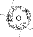
Fig. 7 is the rear view of the aperture unit in the lens barrel.
Fig. 8 is the front elevation of the aperture unit in the lens barrel.
Fig. 9 is the exploded perspective view that the structure of the focusing driving mechanism in the lens barrel is shown.
Figure 10 is the stereographic map that the structure of a part that focuses on driving mechanism is shown.
Figure 11 is the exploded perspective view that the structure of the anti-unit that quivers in the lens barrel is shown.
Figure 12 is the stereographic map that the assembling completion status of the anti-unit that quivers is shown.
Figure 13 is the front elevation that the configuration that focuses on driving mechanism (focus actuator) and the anti-unit that quivers (the first and second anti-actuators that quivers) is shown.
Figure 14 is the front elevation that the configuration that focuses on driving mechanism (focus actuator), the anti-unit that quivers (the first and second anti-actuators that quivers) and aperture unit (diaphragm actuator, shutter actuator and ND actuator) is shown.
Figure 15 is the block scheme that the circuit of picture pick-up device is shown.
Embodiment
Below, exemplary embodiment of the present invention is described with reference to the accompanying drawings.
Fig. 1 to Fig. 6 shows the structure as the lens barrel of the picture pick-up device of the optical device of an embodiment of the invention (digital still camera or video camera).Fig. 1 is the sectional view that is in the lens barrel of retracted position (reception position), and Fig. 2 is the last cut-open view that is in the lens barrel of retracted position.Fig. 3 is the sectional view that is in the lens barrel of WIDE position (camera positions), and Fig. 4 is the last cut-open view that is in the lens barrel of WIDE position.Fig. 5 is the sectional view that is in the lens barrel of TELE position (camera positions), and Fig. 6 is the last cut-open view that is in the lens barrel of TELE position.
In lens barrel, hold the optical system that constitutes by the first lens unit L1 that disposes in turn from object side, the second lens unit L2, the 3rd lens unit (as the correcting lens of the anti-lens that quiver) L3 and the 4th lens unit (as the condenser lens of moving lens) L4.Reference numeral AXL represents the optical axis of optical system.
The cam pin 5a that is arranged on the outer peripheral face of aperture unit 5 engages with cam path 8d on the inner peripheral surface that is formed on cam canister 8.Sleeve part 5b and rotational stop (not shown) are formed on the aperture unit 5, and sleeve part 5b and rotational stop engage with the guide rod 21,22 that is supported by the imaging apparatus substrate 9 of second 2 and explanation after a while, so that sleeve part 5b and rotational stop can move along optical axis direction.
Aperture unit 5 (aperture blades), shutter (blade) and ND wave filter are that control is by arriving the fader control member of the light quantity of image planes (Shuo Ming imaging apparatus 11 after a while) after the optical system.Diaphragm actuator, shutter actuator and ND actuator are corresponding with the 4th actuator (fader control member actuator).
As mentioned above, by the guide rod 21 of second 2 support and 22 maintenance aperture units 5 and the anti-unit that quivers, make the aperture unit 5 and the unit of preventing quivering to move still and can not rotate along optical axis direction.
The gear part (not shown) is formed on the inner peripheral surface of cam canister 8, and rotating force is passed to gear part from zoom motor (for example, step motor) (not shown) via gear row (geararray).Thereby cam canister 8 is rotated driving.When cam canister 8 rotates, Yi Bian cam canister 8 is by being formed on the cam path 8e in the cam canister 8 and being arranged on the joint between the cam pin on the stationary magazine creel 7 and rotating an edge optical axis direction and move.
First 1 by being arranged at first 1 cam pin 1a and being formed on the joint between the cam path 8a in the cam canister 8 and being formed on directly advancing groove and being arranged on directly advancing the joint between the key and do not move along optical axis direction rotationally on the stationary magazine creel 7 in first 1.In other words, the lens barrel in the present embodiment carries out the expanding-contracting action along optical axis direction.
The cam pin 5a of aperture unit 5 engages with cam path 8d in being formed on cam canister 8 and by guide rod 21 and 22 5b of guide sleeve portion and rotational stop 5c, therefore, aperture unit 5 does not move along optical axis direction rotationally owing to be arranged at.
Imaging apparatus 11 and IR-cut/low-pass filter 10 that 9 maintenances of imaging apparatus substrate are made of ccd sensor or cmos sensor.Utilize the screw (not shown) that stationary magazine creel 7 and focusing base component 6 are fixed on the imaging apparatus substrate 9.
Then, with reference to Fig. 9 and Figure 10 the focusing driving mechanism that drives the 4th retainer 4 is described, the 4th retainer 4 keeps condenser lens L4.Fig. 9 is the exploded perspective view that focuses on driving mechanism, and Figure 10 is the stereographic map that the part assembled state that focuses on driving mechanism is shown.
Yoke 61,62 and magnet 63 are fixed on and focus on the base component 6.Yoke 61 has the U word shape and is arranged such that the top and bottom of yoke 61 extend along optical axis direction.Magnet 63 is maintained at the inside of yoke 61.Yoke 61 is inserted into the inside of air core coil 41.Air core coil 41 is disposed in apart from the distance of yoke 61 and magnet 63 predetermined spaces.
When air core coil 41 was applied electric current, owing to the effect of the magnetic circuit that is formed by yoke 61,62 and magnet 63, the 4th retainer 4 (being condenser lens L4) moved along optical axis direction, promptly moves along optical axis.
Be installed to the 4th retainer 4 along the scrambler magnet (encoder magnet) 43 that optical axis direction extends.Be fixed on the MR sensor (magnetoresistive transducer) 67 that focuses on the base component 6 and be disposed in the position relative with scrambler magnet 43 as magnetic sensor.Scrambler magnet 43 and the 4th retainer 4 move with change with respect to MR sensor 67 and act on the magnetic (magnetism) on the MR sensor 67 and change output from MR sensor 67.Change based on this output, CPU shown in Figure 15 (controller) 100 can detect the position of the 4th retainer 4.CPU 100 is with reference to controlling the electric current that is applied to air core coil 41 by the positional information of MR sensor 67 detected the 4th retainers 4, so that condenser lens L4 moves to target location (position in focus).
The structure of the anti-unit that quivers then, is described with reference to Figure 11 and Figure 12.Figure 11 is the exploded perspective view of the anti-unit that quivers, and Figure 12 is the stereographic map that the assembling completion status of the anti-unit that quivers is shown.
The 3rd retainer 3 keeps the 3rd retainer 3 by sensor retainer 32 via three volute springs 35, so that can be shifted along the direction with the optical axis direction quadrature.Volute spring 35 also has the 3rd retainer 3 is applied function towards the power of sensor retainer 32.Ball 36 is disposed in the planar portions (not shown) of three circumferential positions of the edge that is formed on the 3rd retainer 3 and is formed between the recess 3e of three circumferential positions of edge on the sensor retainer 32.The power that applies by volute spring 35 is clipped in ball 36 between planar portions and the recess 3e.Thereby the 3rd retainer 3 can not be shifted with respect to the state lower edge of inclined light shaft and the direction of optical axis direction quadrature.
The 3rd retainer 3 is made of magnet 33a and coil 34a along the first anti-actuator that quivers of directions X displacement, the 3rd retainer 3 is made of magnet 33b and coil 34b along the second anti-actuator that quivers of Y direction displacement.The first and second anti-actuators that quiver are corresponding with first and second actuators respectively.
When electric current flows to coil 34a and 34b, drive the 3rd retainer 3 by being used between the magnetic of the magnetic that produces among coil 34a and the 34b and magnet 33a and 33b, so that the 3rd retainer 3 is along directions X and the displacement of Y direction.
Then, with reference to Figure 13 the first and second anti-actuators and as the configuration of the voice coil motor of above-mentioned focus actuator of quivering are described.Figure 13 observes (observing along optical axis direction) figure when preventing quivering the unit when the direction from optical axis AXL.Suppose not carry out state that anti-vibration does, promptly suppose that the optical axis state consistent with the optical axis AXL of optical system that the 3rd retainer 3 (correcting lens L3) is disposed in neutral position and correcting lens L3 illustrates this embodiment.
In Figure 13, be defined as a-quadrant and B zone respectively with respect to upper-side area and the underside area of the straight line H that extends through the position of optical axis AXL and along left and right directions.In addition, be defined as B1 zone and B2 zone respectively with respect to left field and right side area through the position of the position of optical axis AXL and focus actuator and the straight line V that extends along the vertical direction.
In this embodiment, statement " first anti-actuator and the second anti-actuator that quivers of quivering is disposed in the B zone " is not to only limit to first anti-quiver actuator and the second anti-actuator integral body of quivering to be included in situation in the B zone, but can comprise that the center O 1 of at least the first anti-the quiver actuator and the second anti-actuator that quivers and O2 are disposed in the situation in the B zone yet.In this case, even the top of the anti-actuator that quivers is projected in the a-quadrant a little, if center O 1 and O2 are arranged in the B zone, the then anti-actuator that quivers also is considered to be arranged in the B zone.This also is suitable for the situation that the top of the anti-actuator that quivers is projected in the a-quadrant a little owing to anti-vibration.
The center O separately 1 of the first and second anti-actuators that quiver and O2 need not to be and are positioned at more RCly, and the point that is positioned near the scope (central part) the center also is an acceptable.In addition, each center O 1 and O2 can be when the shape of the anti-actuator that quivers when optical axis direction is observed or the centre of gravity place of area, perhaps can be magnetic center or magnetic center of gravity.
The first and second anti-actuators that quiver are disposed in respectively in B1 zone and the B2 zone.Statement " the first and second anti-actuators that quiver are disposed in respectively in B1 zone and the B2 zone " comprises that the first and second anti-actuator integral body of quivering are included in the situation in B1 zone and the B2 zone respectively.Yet, can comprise that also center O 1 and O2 at least lay respectively at the situation in B1 zone and the B2 zone.
Thereby in the present embodiment, when when optical axis direction is observed, the first and second anti-actuators that quiver are disposed in respect in the optical axis AXL B zone opposite with the a-quadrant of layout focus actuator.In addition, the first and second anti-actuators that quiver are disposed in respectively with respect in optical axis AXL reciprocal B1 zone and the B2 zone.
When optical axis direction is observed, be positioned under the state of neutral position at the 3rd retainer 3, the focus actuator and first anti-distance L X and the focus actuator and second of quivering between the actuator prevent that the distance L Y that quivers between the actuator is equal to each other.Distance in this embodiment is position O3 and anti-quiver center (or central part) O1 of actuator and the distance between the O2 of focus actuator.
In other words, in the present embodiment, when when optical axis direction is observed, the first and second anti-actuators that quiver are disposed in about the position through the straight line V symmetry of the position O3 of the position of optical axis AXL and focus actuator.
In the present embodiment, when when optical axis direction is observed, focus actuator is disposed in apart from the position of optical axis first distance, and the first and second anti-actuators that quiver all are disposed in apart from the position of focus actuator second distance, and this second distance is than first distance.
When optical axis direction is observed, make the 3rd retainer 3 be disposed in the positions that phase place differs 90 degree each other along the first and second anti-actuators that quiver of orthogonal directions X and the displacement of Y direction respectively.Therefore, we can say, the first and second anti-actuators that quiver are arranged such that, connect center (or central part) O1 of the first anti-actuator that quivers and optical axis AXL the position straight line and connect center (or central part) O2 of the second anti-actuator that quivers and the straight line of the position of optical axis AXL is 45 with the angle between the straight line V and spends.
Distance L X and LY needn't be strictly consistent each other, and being considered to each other, the difference of the degree of the distance of unanimity also is acceptable.In addition, about the angle of symmetry or 45 degree, need not to be strict symmetry or 45 degree, the value that is positioned at the scope that is considered to identical with above-mentioned value basically also is an acceptable.
As mentioned above, if the first and second anti-actuators that quiver are disposed in the B zone (B1 zone and B2 zone), then distance L X and LY needn't be equal to each other or needn't be disposed in the position of above-mentioned symmetric position or 45 angles of spending.
The configuration of the aforesaid first and second anti-actuators that quiver can make first and second anti-quiver actuator the two away from location, focus actuator ground.As TOHKEMY 2003-295249 communique is disclosed, compare with the situation of two anti-actuators that quiver of configuration, though focus actuator and an anti-distance of quivering between the actuator are short slightly,, focus actuator and another anti-distance of quivering between the actuator can be extended significantly.Therefore, can alleviate focus actuator and two anti-magnetic interference of quivering between the actuator.In addition, can avoid from the magnetic leakage flux of two anti-actuators that quiver to the influence of MR sensor 67 or from the influence of the magnetic leakage flux of focus actuator Hall element 37a and 37b.
Then, with reference to Figure 14 explanation when the focus actuator when optical axis direction is observed, the configuration relation between actuator, diaphragm actuator, shutter actuator and the ND actuator of preventing quivering.
In Figure 14, as mentioned above, Reference numeral 51 expression diaphragm actuators, Reference numeral 52a represents to constitute the magnet of shutter actuator 52.Reference numeral 53a represents to constitute the magnet of ND actuator 53.
When optical axis direction is observed, diaphragm actuator 51, shutter actuator 52 and ND actuator 53 are not disposed in and the focus actuator and the first and second anti-actuator overlapping areas of quivering.In shutter actuator 52 and ND actuator 53, magnet 52a and 53a are subjected to the influence of the magnetic force of other actuator.Therefore, statement " when when optical axis direction is observed; shutter actuator 52 and ND actuator 53 are not disposed in and the focus actuator and the first and second anti-actuator overlapping areas of quivering " means: when when optical axis direction is observed, magnet 52a and 53a are not disposed in and prevent quivering the actuator overlapping areas with focus actuator and first and second.
In addition, in the present embodiment, all focus actuator, first and second anti-quiver actuator, diaphragm actuator 51, shutter actuator 52 and the ND actuators 53 all are disposed in the inside as the stationary magazine creel 7 of the barrel member with drum.
More specifically, when when optical axis direction is observed, diaphragm actuator 51 is disposed in the focus actuator and first anti-the quivering between the actuator.Shutter actuator 52 is disposed in first and second anti-the quivering between the actuator.In addition, ND actuator 53 is disposed in the focus actuator and second anti-the quivering between the actuator.
In order to obtain the big moving range of condenser lens L4, focus actuator comprises yoke 61 and the magnet of growing along the length of optical axis direction 63.Therefore, when when optical axis direction is observed, diaphragm actuator 51 is arranged to not overlapping with focus actuator, thereby with space-efficient configuration diaphragm actuator 51.
In the structure of the first and second anti-actuators that quiver in the present embodiment, emit most of magnetic force of the magnet of each anti-actuator that quivers along optical axis direction.Therefore, when when optical axis direction is observed, shutter actuator 52 and ND actuator 53 are arranged to not overlapping with the first and second anti-actuators that quiver, with the influence that not interfered by magnetic.
In the present embodiment, magnetic shield panel 64 is disposed on two sides of focus actuator, to reduce the magnetic leakage flux from focus actuator.Thereby combination is anti-quivers actuator with respect to the configuration of above-mentioned focus actuator, and the magnetic that can reduce between these actuators is interfered.
In addition, in the present embodiment, focus actuator is long on optical axis direction.Therefore, focus actuator be arranged to common positive position use focus actuator under the situation of picture pick-up device be positioned in lens barrel above, make can not produce ghost image or flash of light by the light that is reflected on the focus actuator.In this case, two anti-actuators that quiver are positioned in the below of lens barrel.
The structure of the circuit of the CPU 100 that Figure 15 has all illustrated above showing and comprising, vibration sensor 101, first and second anti-quiver actuator X and Y, Hall element 37a and 37b, focus actuator and MR sensors 67.Vibration sensor 101 is made of angular-rate sensor, acceleration transducer etc. and comes output signal according to the vibration of picture pick-up device.CPU 100 amplifies the signal that comes self-vibrating sensor 101 and this signal is carried out integration tremble displacement signal to produce, thereby calculates the target location that the 3rd retainer 3 (correcting lens L3) is displaced to based on this vibration displacement signal.
As mentioned above, according to above-mentioned embodiment, when when optical axis direction is observed, focus actuator, first and second anti-quiver actuator, diaphragm actuator, shutter actuator and the ND actuators are arranged to not overlap each other.Therefore, the magnetic that can alleviate between these actuators is interfered.In addition, because all these actuators all are disposed in the inside of stationary magazine creel (barrel member), therefore, can make the lens barrel miniaturization.In addition, the lens barrel that also can realize comprising these actuators and can carry out expanding-contracting action.
According to above-mentioned embodiment,, therefore, can alleviate the first and second anti-magnetic that quiver between actuator and the focus actuator and interfere because that the first and second anti-actuators that quiver are arranged to from focus actuator is enough far away.When magnetic sensor is used to detect the position of condenser lens or correcting lens, can reduce first and second anti-quiver activate or focus actuator to the magnetic influence of magnetic sensor.
As mentioned above, according to present embodiment, when when optical axis direction is observed, first to fourth all actuators all is arranged to not overlap each other.Therefore, the magnetic that can alleviate between first to fourth actuator is interfered.In addition,, therefore, can make the lens barrel miniaturization because first to fourth all actuators all is disposed in the inside of barrel member, in addition, the lens barrel that also can realize comprising first to fourth actuator and can carry out expanding-contracting action.
For example, in the above-described embodiment, diaphragm actuator is disposed in the focus actuator and first anti-the quivering between the actuator, and shutter actuator is disposed in first and second anti-the quivering between the actuator.In addition, the ND actuator is disposed in the focus actuator and second anti-the quivering between the actuator.Yet the configuration relation of diaphragm actuator, shutter actuator and ND actuator also can be changed each other.
The situation of the diaphragm actuator, shutter actuator and these three actuators of ND actuator that comprise as the 4th actuator has been described in the above-described embodiment.Yet, the invention is not restricted to comprise the situation of all these three actuators, but also applicable to one or two being set, being the situation of at least one the 4th actuator.
In addition, the configuration relation of the actuator in the above-mentioned embodiment only is an example.In other words, when when optical axis direction is observed, diaphragm actuator, shutter actuator and ND actuator only need to be arranged to not overlapping with the focus actuator and the first and second anti-actuators that quiver, and this focus actuator and the first and second anti-actuators that quiver are arranged to not overlap each other.
In the above-described embodiment, illustrated that magnetic sensor is used to detect the situation of the position of correcting lens or condenser lens, still, replaced this situation, also can use optical sensor.
In the above-described embodiment, picture pick-up device has been described, still, the present invention is also applicable to interchangeable lens (optical device).
Though the present invention has been described with reference to exemplary embodiment,, should be appreciated that, the invention is not restricted to disclosed exemplary embodiment.The scope of appended claims will meet the wideest explanation, to comprise all modification, equivalent structure and function.
Claims (8)
1. optical device, this optical device comprises:
The anti-lens that quiver, its can with respect to the optical axis of optical system with the direction superior displacement of described light shaft positive cross;
Moving lens, it can move along described optical axis;
The fader control member, it is configured to control the light quantity by described optical system;
First actuator and second actuator, each side in this first actuator and second actuator includes magnet and coil, this first actuator and second actuator be constructed such that described anti-quiver lens with the different directions from each other superior displacement of described light shaft positive cross;
The 3rd actuator, it comprises magnet and coil and is constructed such that described moving lens moves;
The 4th actuator, it is configured to operate described fader control member; And
Barrel member, it holds described anti-quiver lens, described moving lens, described fader control member and described first to fourth actuator,
Wherein, when when optical axis direction is observed, described first to fourth actuator is disposed in the inside of described barrel member in the mode that does not overlap each other.
2. optical device according to claim 1 is characterized in that,
When described optical axis direction is observed, described the 4th actuator is disposed between described first actuator and described second actuator.
3. optical device according to claim 1 and 2 is characterized in that,
Described first actuator and described second actuator are arranged in respect to described optical axis and arrange the regional opposite zone of described the 3rd actuator, and described first actuator and described second actuator are arranged in respect to the reciprocal zone of described optical axis.
4. optical device according to claim 1 and 2 is characterized in that,
When described optical axis direction is observed, be positioned under the state of neutral position at the described anti-lens that quiver, the distance between distance between described first actuator and described the 3rd actuator and described second actuator and described the 3rd actuator is equal to each other.
5. optical device according to claim 1 and 2 is characterized in that,
When described optical axis direction is observed, described the 3rd actuator is disposed in the position apart from described optical axis first distance, the two all is disposed in the position of described the 3rd actuator second distance of distance described first actuator and described second actuator, and described second distance is than described first distance.
6. optical device according to claim 1 and 2 is characterized in that,
When described optical axis direction is observed, described first actuator and described second actuator are disposed in about the position through the straight line symmetry of the position of described optical axis and described the 3rd actuator.
7. optical device according to claim 1 and 2 is characterized in that,
When described optical axis direction is observed, the described magnet and the described coil that constitute each side in described first actuator and described second actuator are arranged to overlap each other.
8. optical device according to claim 1 and 2 is characterized in that,
Described barrel member is to constitute the member that carries out the lens barrel of expanding-contracting action along described optical axis direction.
Applications Claiming Priority (3)
| Application Number | Priority Date | Filing Date | Title |
|---|---|---|---|
| JP2008236456 | 2008-09-16 | ||
| JP2008236456A JP5202202B2 (en) | 2008-09-16 | 2008-09-16 | Optical equipment |
| JP2008-236456 | 2008-09-16 |
Publications (2)
| Publication Number | Publication Date |
|---|---|
| CN101676788A CN101676788A (en) | 2010-03-24 |
| CN101676788B true CN101676788B (en) | 2011-12-07 |
Family
ID=42007311
Family Applications (1)
| Application Number | Title | Priority Date | Filing Date |
|---|---|---|---|
| CN2009101729906A Expired - Fee Related CN101676788B (en) | 2008-09-16 | 2009-09-15 | Optical apparatus |
Country Status (3)
| Country | Link |
|---|---|
| US (1) | US7949243B2 (en) |
| JP (1) | JP5202202B2 (en) |
| CN (1) | CN101676788B (en) |
Families Citing this family (17)
| Publication number | Priority date | Publication date | Assignee | Title |
|---|---|---|---|---|
| TWI491251B (en) * | 2009-12-30 | 2015-07-01 | Hon Hai Prec Ind Co Ltd | Camera module |
| JP5634172B2 (en) * | 2010-08-31 | 2014-12-03 | キヤノン株式会社 | Lens barrel and optical apparatus having the same |
| JP5679744B2 (en) * | 2010-09-13 | 2015-03-04 | キヤノン株式会社 | Lens barrel |
| JP5822552B2 (en) * | 2011-06-16 | 2015-11-24 | キヤノン株式会社 | Lens barrel and imaging device |
| JP6271974B2 (en) | 2013-12-02 | 2018-01-31 | キヤノン株式会社 | Image blur correction device, lens barrel, and imaging device |
| KR20160045385A (en) | 2014-10-17 | 2016-04-27 | 엘지이노텍 주식회사 | Lens driving unit and camera module including the same |
| EP3040753B1 (en) | 2014-12-30 | 2024-02-21 | LG Innotek Co., Ltd. | Lens moving apparatus |
| US20160341975A1 (en) | 2015-05-21 | 2016-11-24 | Jahwa Electronics Co., Ltd. | Camera lens module |
| CN109188643A (en) * | 2015-05-29 | 2019-01-11 | 磁化电子株式会社 | Camera lens module |
| JP2017083582A (en) * | 2015-10-26 | 2017-05-18 | Hoya株式会社 | Imaging device |
| WO2017187933A1 (en) * | 2016-04-28 | 2017-11-02 | 富士フイルム株式会社 | Optical device and imaging device |
| CN109716634B (en) | 2016-06-03 | 2020-12-01 | 富士胶片株式会社 | Voice coil motor, lens moving device, and imaging device |
| WO2017208876A1 (en) | 2016-06-03 | 2017-12-07 | 富士フイルム株式会社 | Voice coil motor, lens moving device, and imaging device |
| JP6635356B2 (en) | 2017-01-24 | 2020-01-22 | パナソニックIpマネジメント株式会社 | Lens barrel |
| JP7099472B2 (en) * | 2017-09-29 | 2022-07-12 | 株式会社ニコン | Lens barrel and image pickup device |
| JP7199955B2 (en) * | 2018-12-20 | 2023-01-06 | 株式会社タムロン | lens barrel |
| WO2024053542A1 (en) * | 2022-09-09 | 2024-03-14 | ソニーグループ株式会社 | Linear actuator, interchangeable lens, and image capturing device |
Family Cites Families (5)
| Publication number | Priority date | Publication date | Assignee | Title |
|---|---|---|---|---|
| JP2002236248A (en) * | 2001-02-13 | 2002-08-23 | Matsushita Electric Ind Co Ltd | Lens barrel |
| JP2003075880A (en) * | 2001-08-31 | 2003-03-12 | Canon Inc | Optical device |
| JP4143318B2 (en) * | 2002-03-29 | 2008-09-03 | キヤノン株式会社 | Lens barrel and optical apparatus using the same |
| JP2008197388A (en) * | 2007-02-13 | 2008-08-28 | Nikon Corp | Image shake correction device, lens barrel, and optical apparatus |
| JP4958804B2 (en) * | 2008-01-22 | 2012-06-20 | キヤノン株式会社 | Optical lens barrel and imaging device |
-
2008
- 2008-09-16 JP JP2008236456A patent/JP5202202B2/en not_active Expired - Fee Related
-
2009
- 2009-09-14 US US12/559,025 patent/US7949243B2/en not_active Expired - Fee Related
- 2009-09-15 CN CN2009101729906A patent/CN101676788B/en not_active Expired - Fee Related
Also Published As
| Publication number | Publication date |
|---|---|
| JP2010072062A (en) | 2010-04-02 |
| JP5202202B2 (en) | 2013-06-05 |
| US7949243B2 (en) | 2011-05-24 |
| CN101676788A (en) | 2010-03-24 |
| US20100067889A1 (en) | 2010-03-18 |
Similar Documents
| Publication | Publication Date | Title |
|---|---|---|
| CN101676788B (en) | Optical apparatus | |
| JP5430074B2 (en) | Optical apparatus and imaging apparatus including the same | |
| US8830583B2 (en) | Position controller for removable optical element | |
| JP5611579B2 (en) | Optical element position control device | |
| JP4764075B2 (en) | Image blur correction device and lens barrel provided with the image blur correction device | |
| US8773762B2 (en) | Lens barrel having an image-stabilizing insertable/removable optical element | |
| JP2013134455A (en) | Image blur correction device and lens drive device | |
| JP4992478B2 (en) | Camera shake correction unit, lens barrel, camera | |
| JP2008197388A (en) | Image shake correction device, lens barrel, and optical apparatus | |
| JP5436014B2 (en) | Image blur correction device | |
| JP2011123360A (en) | Device for control of optical element | |
| JP2018040864A (en) | Image blur correction device, lens device, and imaging device | |
| US11825199B2 (en) | Driving device capable of properly restricting translational movement and rotational movement, image capturing apparatus, and method of controlling driving device | |
| JP4950425B2 (en) | Optical device | |
| JP2008197354A (en) | Lens drive unit and optical apparatus | |
| JP6564007B2 (en) | Image blur correction device and lens driving device | |
| JP5181542B2 (en) | Blur correction device, electronic equipment | |
| JP5448629B2 (en) | Optical unit and optical equipment | |
| JP2010039083A (en) | Optical vibration-proof device and optical equipment | |
| JP2016057386A (en) | Image tremor correction device and optical device having the same | |
| JP6157239B2 (en) | Lens barrel and imaging device | |
| JP5172024B2 (en) | Optical device | |
| JP2016122079A (en) | Lens barrel with shake correction function | |
| CN114339026A (en) | Camera module and electronic apparatus | |
| JP2019095627A (en) | Tremor-proof lens barrel |
Legal Events
| Date | Code | Title | Description |
|---|---|---|---|
| C06 | Publication | ||
| PB01 | Publication | ||
| C10 | Entry into substantive examination | ||
| SE01 | Entry into force of request for substantive examination | ||
| C14 | Grant of patent or utility model | ||
| GR01 | Patent grant | ||
| CF01 | Termination of patent right due to non-payment of annual fee |
Granted publication date: 20111207 Termination date: 20200915 |
|
| CF01 | Termination of patent right due to non-payment of annual fee |