JP6157239B2 - Lens barrel and imaging device - Google Patents
Lens barrel and imaging device Download PDFInfo
- Publication number
- JP6157239B2 JP6157239B2 JP2013133635A JP2013133635A JP6157239B2 JP 6157239 B2 JP6157239 B2 JP 6157239B2 JP 2013133635 A JP2013133635 A JP 2013133635A JP 2013133635 A JP2013133635 A JP 2013133635A JP 6157239 B2 JP6157239 B2 JP 6157239B2
- Authority
- JP
- Japan
- Prior art keywords
- movable member
- optical axis
- drive unit
- electromagnetic drive
- image blur
- Prior art date
- Legal status (The legal status is an assumption and is not a legal conclusion. Google has not performed a legal analysis and makes no representation as to the accuracy of the status listed.)
- Expired - Fee Related
Links
Images


Description
本発明は、像ブレ補正装置を備えるレンズ鏡筒、及びレンズ鏡筒を備える撮像装置に関する。 The present invention relates to a lens barrel provided with an image blur correction device and an imaging device provided with the lens barrel.
デジタルカメラ等のレンズ鏡筒に搭載される像ブレ補正装置は、像ブレ補正光学系としての補正レンズ又は撮像素子を保持する可動部材を光軸と略直交する面内の2方向に駆動することで、撮影時に発生する手ブレ等による影響を緩和する。 An image blur correction device mounted on a lens barrel of a digital camera or the like drives a movable lens holding a correction lens or an image sensor as an image blur correction optical system in two directions in a plane substantially orthogonal to the optical axis. This reduces the effects of camera shake that occurs during shooting.
従来のこの種の像ブレ補正装置としては、固定部材を間に挟んで光軸方向の前後にそれぞれ第1の補正レンズを保持する第1の可動部材と、第2の補正レンズを保持する第2の可動部材とを配置したものが提案されている(特許文献1)。この提案では、第1の可動部材及び第2の可動部材をそれぞれ独立して光軸と略直交する面内の2方向に駆動することで、像ブレ補正装置の補正可能な角度が増加できるとしている。 As a conventional image blur correction apparatus of this type, a first movable member that holds a first correction lens and a second correction lens that hold a first correction lens in front and rear in the optical axis direction with a fixed member interposed therebetween, respectively. The thing which arrange | positioned 2 movable members is proposed (patent document 1). In this proposal, the correctable angle of the image blur correction device can be increased by driving the first movable member and the second movable member independently in two directions in a plane substantially orthogonal to the optical axis. Yes.
ところで、上記特許文献1の像ブレ補正装置において、ズーミングやフォーカシング等によって撮影光学系を構成するレンズ群同士の間隔が変化したとき、それに応じて第1及び第2の可動部材の光軸方向の距離を変えて光学性能の向上を図ることが考えられる。 By the way, in the image blur correction apparatus of Patent Document 1, when the distance between the lens groups constituting the photographing optical system is changed by zooming, focusing, or the like, the optical axis direction of the first and second movable members is accordingly changed. It is conceivable to improve the optical performance by changing the distance.
しかし、上記特許文献1では、第1の可動部材及び第2の可動部材は、共通する固定部材に対して光軸と略直交する面内を移動可能に支持されているため、第1の可動部材と第2の可動部材との光軸方向の距離は一定となる。このため、ズーミングやフォーカシング等によってレンズ群同士の間隔が変化した場合に、像ブレ補正の光学性能の向上を図ることが難しい。 However, in Patent Document 1, the first movable member and the second movable member are supported so as to be movable in a plane substantially perpendicular to the optical axis with respect to the common fixed member. The distance in the optical axis direction between the member and the second movable member is constant. For this reason, it is difficult to improve the optical performance of image blur correction when the distance between the lens groups changes due to zooming, focusing, or the like.
一方、第1及び第2の可動部材の光軸方向の距離を変えて光学性能の向上を図る場合、第1及び第2の可動部材をそれぞれ光軸と略直交する方向に駆動する各電磁駆動部が光軸方向に重なって配置されるため、各電磁駆動部の間に磁気的な相互作用力が発生する。そして、第1及び第2の可動部材の光軸方向の距離が変わると、各電磁駆動部に対する磁気的な相互作用力の影響も変化するため、第1及び第2の可動部材の光軸と略直交する方向での高精度な位置制御が難しくなるという問題がある。 On the other hand, when the optical performance is improved by changing the distance between the first and second movable members in the optical axis direction, each electromagnetic drive that drives the first and second movable members in directions substantially orthogonal to the optical axis, respectively. Since the portions are arranged so as to overlap in the optical axis direction, a magnetic interaction force is generated between the electromagnetic drive portions. When the distance in the optical axis direction of the first and second movable members changes, the influence of the magnetic interaction force on each electromagnetic drive unit also changes, so the optical axes of the first and second movable members There is a problem that highly accurate position control in a substantially orthogonal direction becomes difficult.
そこで、本発明は、ズーミングやフォーカシング等によってレンズ群同士の間隔が変化した場合の像ブレ補正の光学性能の向上を図ると共に、第1及び第2の可動部材の光軸と交差する方向での高精度な位置制御を実現する仕組みを提供することを目的とする。 Therefore, the present invention aims to improve the optical performance of image blur correction when the distance between the lens groups changes due to zooming, focusing, etc., and in the direction intersecting the optical axes of the first and second movable members. An object is to provide a mechanism for realizing high-precision position control.
上記目的を達成するために、本発明のレンズ鏡筒は、第1の像ブレ補正光学系を保持する第1の可動部材、前記第1の可動部材を光軸と交差する方向に移動可能に支持する第1の固定部材、前記第1の可動部材を光軸と交差する第1の方向に駆動する第1の電磁駆動部、及び第1の可動部材を光軸と交差する第2の方向に駆動する第2の電磁駆動部を有する第1の像ブレ補正装置と、第2の像ブレ補正光学系を保持する第2の可動部材、前記第2の可動部材を光軸と交差する方向に移動可能に支持する第2の固定部材、前記第2の可動部材を光軸と交差する第3の方向に駆動する第3の電磁駆動部、及び第2の可動部材を光軸と交差する第4の方向に駆動する第4の電磁駆動部を有する第2の像ブレ補正装置と、を備え、前記第1の像ブレ補正装置は、前記第2の像ブレ補正装置に対して光軸方向に相対的に移動可能とされ、光軸を中心として周方向に90°ごとに4等分した領域をそれぞれ第1領域、第2領域、第3領域、及び第4領域とした場合、前記第1の電磁駆動部は、前記第1領域に配置され、前記第2の電磁駆動部は、前記第2領域に配置され、前記第3の電磁駆動部は、前記第3領域に配置され、前記第4の電磁駆動部は、前記第4領域に配置されることを特徴とする。 In order to achieve the above object, the lens barrel of the present invention has a first movable member that holds the first image blur correction optical system, and the first movable member is movable in a direction intersecting the optical axis. A first fixed member to be supported, a first electromagnetic drive unit that drives the first movable member in a first direction intersecting the optical axis, and a second direction that intersects the first movable member with the optical axis A first image blur correction apparatus having a second electromagnetic drive unit that is driven in a second direction, a second movable member that holds a second image blur correction optical system, and a direction in which the second movable member intersects the optical axis A second fixed member that is movably supported, a third electromagnetic drive unit that drives the second movable member in a third direction that intersects the optical axis, and a second movable member that intersects the optical axis. A second image blur correction device having a fourth electromagnetic drive unit that drives in a fourth direction, and the first image blur compensation device. The apparatus is movable relative to the second image blur correction apparatus in the optical axis direction, and an area divided into four equal parts every 90 ° in the circumferential direction with the optical axis as a center is respectively the first area and the first area. When the second region, the third region, and the fourth region, the first electromagnetic driving unit is disposed in the first region, the second electromagnetic driving unit is disposed in the second region, The third electromagnetic drive unit is disposed in the third region, and the fourth electromagnetic drive unit is disposed in the fourth region.
本発明によれば、ズーミングやフォーカシング等によってレンズ群同士の間隔が変化した場合の像ブレ補正の光学性能の向上を図ることができると共に、第1及び第2の可動部材の光軸と交差する方向での高精度な位置制御を実現することができる。 According to the present invention, it is possible to improve the optical performance of image blur correction when the distance between the lens groups is changed by zooming, focusing, or the like, and intersect the optical axes of the first and second movable members. High-precision position control in the direction can be realized.
以下、本発明の実施形態の一例を図面を参照して説明する。 Hereinafter, an example of an embodiment of the present invention will be described with reference to the drawings.
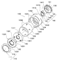
図1は、本発明の実施形態の一例である像ブレ補正装置を備えるレンズ鏡筒の分解斜視図である。図2は、図1に示すレンズ鏡筒の組立体におけるテレ位置での光軸方向に沿う断面図である。図3は、図1に示すレンズ鏡筒の組立体におけるワイド位置での光軸方向に沿う断面図である。なお、本実施形態では、デジタルカメラ等の撮像装置に搭載されるレンズ鏡筒を例に採る。 FIG. 1 is an exploded perspective view of a lens barrel provided with an image blur correction device as an example of an embodiment of the present invention. FIG. 2 is a cross-sectional view along the optical axis direction at the tele position in the lens barrel assembly shown in FIG. FIG. 3 is a cross-sectional view taken along the optical axis direction at the wide position in the lens barrel assembly shown in FIG. In the present embodiment, a lens barrel mounted on an imaging apparatus such as a digital camera is taken as an example.
図1乃至図3に示すように、本実施形態のレンズ鏡筒100は、素子ホルダ102、固定筒103、カム筒104、1群鏡筒110、2群鏡筒120、3群鏡筒130、及び4群鏡筒140を備える。レンズ鏡筒100は、撮影位置と収納位置との間で撮影光学系が光軸方向に移動して撮影倍率を変更するズーム式とされている。
As shown in FIGS. 1 to 3, the
素子ホルダ102は、CCDセンサやCMOSセンサ等の撮像素子101を保持する。また、素子ホルダ102には、4群鏡筒140の後述するメインバー143、サブバー144、及びステッピングモータ145が固定される。
The
固定筒103は、像面側の端部に素子ホルダ102が固定され、被写体側の端部内周部に、1群鏡筒110の後述する1群レンズホルダ112が保持される。また、固定筒103の周壁には、光軸方向に延びる第1直進溝1031、及び第2直進溝1032がそれぞれ周方向に略等間隔で3箇所ずつ形成されている。
In the
第1直進溝1031には、2群鏡筒120の後述する固定地板123に設けられたフォロア1231が係合し、これにより、固定筒103に対して2群鏡筒120が光軸方向に移動可能に支持される。また、第2直進溝1032には、3群鏡筒130の後述する固定地板133に設けられたフォロア1331が係合し、これにより、固定筒103に対して3群鏡筒130が光軸方向に移動可能に支持される。
A
カム筒104は、固定筒103の外周部に回転可能に支持される。カム筒104の周壁には、第1カム溝1041、及び第2カム溝1042がそれぞれ周方向に略等間隔で3箇所ずつ形成されている。
The
第1カム溝1041には、2群鏡筒120の後述する固定地板123に設けられたフォロア1231が追従し、これにより、カム筒104の回転に応じて2群鏡筒120が光軸方向に進退移動する。第2カム溝1042には、3群鏡筒130の後述する固定地板133に設けられたフォロア1331が追従し、これにより、カム筒104の回転に応じて3群鏡筒130が光軸方向に進退移動する。
A
カム筒104の回転位置は、不図示の検出手段によって検出することができる。また、カム筒104の回転は、ユーザによる手動操作でもよいし、不図示のステッピングモータや超音波モータ等の専用の駆動手段によるものでもよい。カム筒104の回転操作により異なる第1カム溝1041及び第2カム溝1042に追従する2群鏡筒120及び3群鏡筒130の光軸方向の相対的な位置を変更することが可能となる。
The rotational position of the
1群鏡筒110は、1群レンズ111を保持する1群レンズホルダ112を有し、固定筒103に固定される。2群鏡筒120は、本発明の第1の像ブレ補正装置の一例に相当し、3群鏡筒130は、本発明の第2の像ブレ補正装置の一例に相当する。なお、2群鏡筒120、及び3群鏡筒130の詳細については、後述する。
The
4群鏡筒140は、4群レンズ141を保持する4群レンズホルダ142を有する。4群レンズ141は、本実施形態では、フォーカスレンズで構成される。4群レンズホルダ142には、スリーブ1411、回転止め溝1412、及びナット1413(図1参照)が設けられている。
The
スリーブ1411は、素子ホルダ102に固定されたメインバー143に光軸方向に移動可能に嵌合され、これにより、4群レンズホルダ142を光軸方向に進退移動可能に保持する。回転止め溝1412は、素子ホルダ102に固定されたサブバー144に係合することで、4群レンズホルダ142がメインバー143を中心として回転することを規制する。ナット1413は、ステッピングモータ145の回転軸に設けられたリードスクリューに螺合される。
The
したがって、ステッピングモータ145を駆動すると、リードスクリューとナット1413とのねじ作用により、4群レンズ141を保持する4群レンズホルダ142が光軸方向に進退移動し、これにより、フォーカシング動作が行われる。
Therefore, when the stepping
次に、図2乃至図5を参照して、2群鏡筒120について説明する。図4は、2群鏡筒120の分解斜視図である。図5は、2群鏡筒120の光軸方向に沿う断面図である。図2乃至図5に示すように、2群鏡筒120は、補正レンズ121、可動部材122、固定地板123、転動ボール124、電磁駆動部125,126、付勢ばね127、位置センサ128、及びセンサホルダ129を備える。
Next, the
可動部材122は、電磁駆動部125の磁石1251及び電磁駆動部126の磁石1261を保持するとともに、中央の開口部に補正レンズ121を保持する。可動部材122は、固定地板123との間で周方向に略等間隔で3箇所配置される転動ボール124によって光軸と略直角に交差(略直交)する面内を移動可能に転動支持される。また、可動部材122には、3つの付勢ばね127の一端が掛止される。ここで、補正レンズ121は、本発明の第1の像ブレ補正光学系の一例に相当し、可動部材122は、本発明の第1の可動部材の一例に相当する。
The
固定地板123は、外周部に径方向外方に突出するフォロア1231が周方向に略等間隔で3箇所形成されている。固定地板123の中央の開口部には、可動部材122が配置され、これにより、可動部材122の光軸と略直交する方向の移動量を制限する。
In the fixed
また、固定地板123は、電磁駆動部125のコイル1252及びヨーク1253を保持するとともに、電磁駆動部126のコイル1262及びヨーク1263を保持する。コイル1252及びヨーク1253は、可動部材122に保持された磁石1251の着磁面に対して光軸方向に対向配置され、コイル1262及びヨーク1263は、可動部材122に保持された磁石1261の着磁面に対して光軸方向に対向配置される。
The fixed
固定地板123には、転動ボール124の受け部が周方向に略等間隔で3箇所設けられている。固定地板123と可動部材122との間に配置される3つの転動ボール124を介して固定地板123に対して可動部材122が光軸と直交する面内にて移動可能に支持される。また、固定地板123には、3つの付勢ばね127の他端が掛止される。ここで、固定地板123は、本発明の第1の固定部材の一例に相当する。
The fixed
電磁駆動部125,126は、ともにボイスコイルモータ等で構成され、電磁駆動部125は、磁石1251、コイル1252、及びヨーク1253を有し、電磁駆動部126は、磁石1261、コイル1262、及びヨーク1263を有する。ここで、電磁駆動部125は、本発明の第1の電磁駆動部の一例に相当し、電磁駆動部126は、本発明の第2の電磁駆動部の一例に相当する。
The
電磁駆動部125は、固定地板123に保持されたコイル1252に電流を流すことで、可動部材122に保持された磁石1251との間にローレンツ力を発生し、可動部材122を光軸と略直交する第1の方向に駆動する。本実施形態では、磁石1251とヨーク1253とでコイル1252を光軸方向に挟み込むようにしているため、磁石1251の作る磁束を効率的に駆動力に変換することができる。
The
電磁駆動部126は、電磁駆動部125に対して90°位相をずらして配置される。そして、固定地板123に保持されたコイル1262に電流を流すことで、可動部材122に保持された磁石1261との間にローレンツ力を発生し、これにより、可動部材122を光軸と略直交し、かつ第1の方向と略直交する第2の方向に駆動する。本実施形態についても、磁石1261とヨーク1263とでコイル1262を光軸方向に挟み込むようにしているため、磁石1261の作る磁束を効率的に駆動力に変換することができる。
The
付勢ばね127は、本実施形態では、引っ張りコイルばねで構成され、一端が可動部材122に掛止され、他端が固定地板123に掛止されて、可動部材122と固定地板123とを互いに近づける方向に付勢する。この付勢力により、可動部材122と固定地板123と間に転動ボール124が挟持され、転動ボール124と固定地板123及び可動部材122との接触状態を保つことができる。
In this embodiment, the urging
位置センサ128は、磁気センサで構成され、2つ配置されて、それぞれ磁石1251及び磁石1261の磁束を検出する。そして、2つの位置センサ128の出力変化に基づき可動部材122の光軸と略直交する面内の位置を検出することができる。
The
センサホルダ129は、2つの位置センサ128をそれぞれ磁石1251及び磁石1261と光軸方向に対向する位置に保持する。また、センサホルダ129は、固定地板123に固定されることで、センサホルダ129と固定地板123との間の空間に可動部材122や電磁駆動部125,126等が収納される。
The
次に、図2及び図3に戻って、3群鏡筒130について説明する。図2及び図3に示すように、3群鏡筒130は、補正レンズ131、可動部材132、固定地板133、転動ボール134(不図示)、電磁駆動部135,136(図7参照)、付勢ばね137(図6参照)、位置センサ138、及びセンサホルダ139を備える。電磁駆動部135は、可動部材132を光軸と略直交する第3の方向に駆動し、電磁駆動部136は、可動部材132を光軸と略直交し、かつ第3の方向と略直交する第4の方向に駆動する。
Next, returning to FIGS. 2 and 3, the
ここで、補正レンズ131は、本発明の第2の像ブレ補正光学系の一例に相当し、可動部材132は、本発明の第2の可動部材の一例に相当し、固定地板133は、本発明の第2の固定部材の一例に相当する。また、電磁駆動部135は、本発明の第3の電磁駆動部の一例に相当し、電磁駆動部136は、本発明の第4の電磁駆動部の一例に相当する。なお、3群鏡筒130は、補正レンズ131の形状、及び補正レンズ131を保持する可動部材132の形状以外は、前述した2群鏡筒120と同様の構成であるため、その説明を省略する。
Here, the
次に、図6及び図7を参照して、2群鏡筒120と3群鏡筒130との位置関係について説明する。図6は、2群鏡筒120及び3群鏡筒130の一部を分解した斜視図である。図7は、2群鏡筒120の可動部材122及び3群鏡筒130の可動部材132を光軸方向から見た図である。
Next, the positional relationship between the
図6及び図7に示すように、2群鏡筒120の電磁駆動部125及び3群鏡筒130の電磁駆動部135は、光軸を間に挟んで互いに反対側に配置される。2群鏡筒120の電磁駆動部126及び3群鏡筒130の電磁駆動部136についても、光軸を間に挟んで互いに反対側に配置される。
As shown in FIGS. 6 and 7, the
即ち、図7に示すように、光軸を中心として周方向に90°ごとに4等分した領域を反時計回りにそれぞれ第1領域〜第4領域とすると、2群鏡筒120の電磁駆動部125は、第1領域に配置され、2群鏡筒120の電磁駆動部126は、第2領域に配置される。また、3群鏡筒130の電磁駆動部135は、第3領域に配置され、3群鏡筒130の電磁駆動部136は、第4領域に配置される。したがって、2群鏡筒120と3群鏡筒130とが光軸方向に接近しても、それぞれの電磁駆動部同士は、周方向の距離が確保され、電磁駆動部同士の磁気的な干渉や機械的な干渉を避けることができる。
That is, as shown in FIG. 7, when the regions divided into four equal parts in the circumferential direction about 90 ° around the optical axis are defined as first region to fourth region in the counterclockwise direction, the electromagnetic drive of the
この効果について、図7及び図8を参照して、2群鏡筒120の電磁駆動部125が3群鏡筒130の電磁駆動部136に与える磁気干渉量を例に挙げて説明する。図8は、本発明例及び比較例における電磁駆動部125,136間の距離と電磁駆動部125が電磁駆動部136に与える磁気干渉量との関係を示すグラフ図である。ここで、本発明例では、図7に示すように、電磁駆動部125,136が互いに90°位相をずらして配置され、比較例では、電磁駆動部125,136が光軸方向に重ねて配置されるものとする。
This effect will be described with reference to FIGS. 7 and 8 by taking as an example the amount of magnetic interference that the
電磁駆動部125と電磁駆動部136とが光軸方向に最も近づく、撮影光学系を広角側に変倍させた状態で、電磁駆動部125と電磁駆動部136との光軸方向の距離は1.8mmとする。
The distance in the optical axis direction between the
この状態において、比較例では、電磁駆動部125,136が光軸方向に重ねて配置されるので、電磁駆動部125,136の中心点間の距離は、1.8mmである。これに対し、本発明例では、電磁駆動部125,136の中心点間の距離(図7のV1−V4間の距離)は、8.59mmとなる。
In this state, in the comparative example, since the
電磁駆動部125による電磁駆動部136への磁気干渉量の大きさは、電磁駆動部125を単一の磁極子と仮定すると、図8に示すように、電磁駆動部125,136間の距離の二乗に反比例する。このため、電磁駆動部125,136の中心点間の距離が1.8mmの比較例における磁気干渉量を100%として相対的に比較すると、本発明例における磁気干渉量は、電磁駆動部125,136間の距離の比(1.8/8.59)の二乗の0.04倍に低減する。このように、本発明例では、電磁駆動部125,135間の磁気干渉量を小さくすることができる。
Assuming that the
また、本実施形態では、2群鏡筒120の電磁駆動部125,126は、3群鏡筒130側にヨーク1253,1263が配置されるので、電磁駆動部125,126の発生する磁束が3群鏡筒130に与える影響を小さくすることができる。同様に、3群鏡筒130の電磁駆動部135,136は、2群鏡筒120側にヨーク1353,1363が配置されるので、電磁駆動部135,136の発生する磁束が2群鏡筒120に与える影響を小さくすることができる。
In the present embodiment, the
これにより、2群鏡筒120と3群鏡筒130とを光軸方向に接近させても、電磁駆動部同士の磁気干渉をより小さくすることができ、2群鏡筒120と3群鏡筒130との光軸方向の距離を広い範囲で設定することができる。
Accordingly, even when the
また、本実施形態では、2群鏡筒120の可動部材122と3群鏡筒130の可動部材132との間に、2群鏡筒120の固定地板123及び3群鏡筒130の固定地板133が配置される。可動部材122は、固定地板123に対して転動ボール124を介して転動可能に支持されるが、落下等による衝撃を受けると、固定地板123の反対側に浮き上がる。また、可動部材132は、固定地板133に対して転動ボール134(不図示)を介して転動可能に支持されるが、落下等による衝撃を受けると固定地板133の反対側に浮き上がる。
In this embodiment, the fixed
したがって、上記のような配置とすることにより、2群鏡筒120の可動部材122と3群鏡筒130の可動部材132は、衝撃を受けても互いの距離は狭くならない。このため、可動部材122と可動部材132との光軸方向の距離を短くしても、互いの接触を避けることができる。
Therefore, with the arrangement as described above, the distance between the
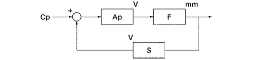
次に、図9及び図10を参照して、2群鏡筒120による像ブレ補正方法について説明する。図9は、2群鏡筒120の電磁駆動部125の駆動を制御する制御回路のブロック図である。なお、2群鏡筒120の電磁駆動部126、及び3群鏡筒130の電磁駆動部135,136についても、図9と同様の制御回路が用いられるため、ここでは、2群鏡筒120の電磁駆動部125についてのみ説明する。
Next, an image blur correction method using the
図9において、Cpは、可動部材122に保持される補正レンズ121の光軸と略直交する方向での目標位置を電圧に変換した指令値である。目標位置の算出は、レンズ鏡筒に取り付けられた角加速度計の出力値を積分および位相補償する方法や、撮像素子から得られた画像情報より計算する方法などの、公知の方法を用いることができる。
In FIG. 9, Cp is a command value obtained by converting a target position in a direction substantially orthogonal to the optical axis of the
Apは、フィードバック回路のループゲイン係数である。与えられた指令値Cpと位置センサS(位置センサ128に相当)によって得られた可動部材122の位置との差をループゲイン係数Apにより増幅し、電磁駆動部125にその差に応じた電圧を入力する。本実施形態では、後述するように、ループゲイン係数Apの値を複数用意し、撮影光学系の変倍操作に応じてその値を変更する。
Ap is a loop gain coefficient of the feedback circuit. A difference between the given command value Cp and the position of the
Fは、電磁駆動部125に入力された電圧と可動部材122の変位量との変換係数である。可動部材122の変位量と位置センサSの出力電圧とは、ほぼ線形近似できるような関係となっている。変換係数Fは、電磁駆動部125の推力定数、コイル1252の抵抗やインピーダンス、入力電圧の周波数、可動部材122の質量、付勢ばね127のばね定数、摩擦などによって決まる。このようなフィードバック制御回路により、補正レンズ121の位置を指令値Cpに対して精度よく追従させることができる。
F is a conversion coefficient between the voltage input to the
次に、図10を参照して、2群鏡筒120の位置センサ128の出力について詳しく説明する。図10は、位置センサ128の出力電圧yと可動部材122の光軸と略直交する方向の変位量xとの関係を示すグラフ図である。
Next, the output of the
本実施形態では、撮影光学系の変倍操作によってレンズ群同士の間隔が変化したとき、それに応じて2群鏡筒120と3群鏡筒130との光軸方向の距離を変えて像ブレ補正の光学性能の向上を図る。その際、2群鏡筒120の位置センサ128と3群鏡筒130の磁石1351等の強磁性体との位置関係が変化する。
In the present embodiment, when the distance between the lens groups is changed by the zooming operation of the photographing optical system, the image blur correction is performed by changing the distance in the optical axis direction between the
図10において、撮影光学系がワイド位置にあるとき、実線で示す曲線となり、撮影光学系がテレ位置にあるとき、破線で示す曲線となる。このように、2群鏡筒120の磁石1251,1261以外から位置センサ128が受ける磁力の影響は、3群鏡筒130の相対位置に応じて再現性のある変化をする。本実施形態では、2群鏡筒120と3群鏡筒130との光軸方向の距離が変化したとき、位置センサ128が3群鏡筒130の磁石1351等から受ける磁力の影響が変化しないよう、位置センサ128の出力電圧yと可動部材122の変位量xとの関係を変更する。
In FIG. 10, when the photographing optical system is at the wide position, the curve is indicated by a solid line, and when the photographing optical system is at the tele position, the curve is indicated by a broken line. Thus, the influence of the magnetic force received by the
具体的には、可動部材122の変位量xと位置センサ128の出力電圧yとの間の比例定数である位置センサ128のゲイン係数Aと、位置センサ128の出力電圧のオフセット量Bと、を複数用意して不図示のメモリ等に記憶しておく。そして、不図示の制御部は、2群鏡筒120と3群鏡筒130の光軸方向の位置関係に応じて、位置センサ128が3群鏡筒130の磁石1351等から受ける磁力の影響が変化しないように適切なゲイン係数A及びオフセット量Bの値を選択する。これにより、2群鏡筒120と3群鏡筒130の光軸方向の位置変化による磁気干渉の影響をさらに低減することができる。
Specifically, the gain coefficient A of the
同様の理由で、2群鏡筒120と3群鏡筒130の光軸方向の位置関係に応じて、電磁駆動部125の推力定数等も再現性のある変化をする。そのため、制御系の特性を最適化するループゲイン係数Apの値も2群鏡筒120と3群鏡筒130の光軸方向の位置関係に応じて変化する。本実施形態では、2群鏡筒120と3群鏡筒130の光軸方向の位置関係に応じて、予めメモリ等に記憶しておいた複数のループゲイン係数Apの値から制御部が最適な値を選択することで、変化した電磁駆動部125の推力定数等を適正な値に変更する。ここで、ゲイン係数A、オフセット量B及びループゲイン係数Apは、可動部材122の変位量xと位置センサ128の出力電圧yとの関係を表すパラメータである。
For the same reason, the thrust constant and the like of the
2群鏡筒120と3群鏡筒130の光軸方向の位置関係の情報は、例えばカム筒103の回転角度の検出結果に基づいて取得することができる。カム筒104の回転角度は、不図示の検出手段を用いて直接検出してもよいし、カム筒104の回転のために専用のモータを用いる場合は、そのモータの回転量を検出する手段を用いてもよい。
Information on the positional relationship of the
以上説明したように、本実施形態では、ズーミングやフォーカシング等によって撮影光学系のレンズ群同士の間隔が変化した場合、それに応じて2群鏡筒120と3群鏡筒130との光軸方向の距離を変えて像ブレ補正の光学性能の向上を図ることができる。また、本実施形態では、2群鏡筒120と3群鏡筒130の光軸方向の位置変化による磁気干渉の影響を低減することができるので、可動部材122,132の光軸と略直交する方向での高精度な位置制御を実現することができる。
As described above, in the present embodiment, when the interval between the lens groups of the photographing optical system changes due to zooming, focusing, or the like, the optical axis direction between the
なお、本発明の構成は、上記実施形態に例示したものに限定されるものではなく、材質、形状、寸法、形態、数、配置箇所等は、本発明の要旨を逸脱しない範囲において適宜変更可能である。 The configuration of the present invention is not limited to that exemplified in the above embodiment, and the material, shape, dimensions, form, number, arrangement location, and the like can be changed as appropriate without departing from the scope of the present invention. It is.
例えば、上記実施形態では、像ブレ補正光学系として補正レンズを例示したが、CCDセンサやCMOSセンサ等の撮像素子を用いてもよい。 For example, in the above embodiment, the correction lens is exemplified as the image blur correction optical system, but an image sensor such as a CCD sensor or a CMOS sensor may be used.
120 2群鏡筒
122 可動部材
122 固定地板
125,126 電磁駆動部
130 3群鏡筒
132 可動部材
132 固定地板
135,136 電磁駆動部
120 Second
Claims (10)
第2の像ブレ補正光学系を保持する第2の可動部材、前記第2の可動部材を光軸と交差する方向に移動可能に支持する第2の固定部材、前記第2の可動部材を光軸と交差する第3の方向に駆動する第3の電磁駆動部、及び第2の可動部材を光軸と交差する第4の方向に駆動する第4の電磁駆動部を有する第2の像ブレ補正装置と、を備え、
前記第1の像ブレ補正装置は、前記第2の像ブレ補正装置に対して光軸方向に相対的に移動可能とされ、
光軸を中心として周方向に90°ごとに4等分した領域をそれぞれ第1領域、第2領域、第3領域、及び第4領域とした場合、前記第1の電磁駆動部は、前記第1領域に配置され、前記第2の電磁駆動部は、前記第2領域に配置され、前記第3の電磁駆動部は、前記第3領域に配置され、前記第4の電磁駆動部は、前記第4領域に配置されることを特徴とするレンズ鏡筒。 A first movable member that holds the first image blur correction optical system, a first fixed member that movably supports the first movable member in a direction that intersects the optical axis, and a light beam that supports the first movable member. A first image blur having a first electromagnetic drive unit that drives in a first direction that intersects the axis, and a second electromagnetic drive unit that drives the first movable member in a second direction that intersects the optical axis. A correction device;
A second movable member that holds the second image blur correction optical system; a second fixed member that movably supports the second movable member in a direction that intersects the optical axis; and A second image blur having a third electromagnetic drive unit that drives in a third direction that intersects the axis, and a fourth electromagnetic drive unit that drives the second movable member in a fourth direction that intersects the optical axis. A correction device,
The first image blur correction device is movable relative to the second image blur correction device in the optical axis direction;
When the regions divided into four equal parts in the circumferential direction about the optical axis are divided into four regions, the first region, the second region, the third region, and the fourth region, respectively, the first electromagnetic driving unit Arranged in one region, the second electromagnetic drive unit is arranged in the second region, the third electromagnetic drive unit is arranged in the third region, and the fourth electromagnetic drive unit is A lens barrel arranged in the fourth region.
前記位置センサの出力に基づき、前記第1の可動部材が目標位置に移動するように前記第1の電磁駆動部に入力する電圧をフィードバック制御する制御手段と、を備えることを特徴とする請求項1又は2に記載のレンズ鏡筒。 A position sensor for detecting a position of the first movable member in a direction intersecting the optical axis with respect to the first fixed member;
And a control unit that feedback-controls a voltage input to the first electromagnetic driving unit so that the first movable member moves to a target position based on an output of the position sensor. The lens barrel according to 1 or 2.
前記制御手段は、前記検出手段により検出された前記第1の像ブレ補正装置に対する前記第2の像ブレ補正装置の光軸方向の相対位置の変化に応じて、前記第1の可動部材の光軸と交差する方向の変位量と前記位置センサの出力との関係を表すパラメータを変更することを特徴とする請求項3に記載のレンズ鏡筒。 Detecting means for detecting a relative position in the optical axis direction of the second image blur correction device with respect to the first image blur correction device;
The control means detects light of the first movable member according to a change in a relative position of the second image blur correction apparatus in the optical axis direction with respect to the first image blur correction apparatus detected by the detection means. The lens barrel according to claim 3, wherein a parameter representing a relationship between a displacement amount in a direction intersecting the axis and an output of the position sensor is changed.
前記第1の固定部材は、前記第1のコイル及び前記第1のヨークを保持することを特徴とする請求項6に記載のレンズ鏡筒。 The first electromagnetic drive unit includes a first magnet, a first coil, and a first yoke, and the first movable member holds the first magnet,
The lens barrel according to claim 6, wherein the first fixing member holds the first coil and the first yoke.
前記第2の固定部材は、前記第2のコイル及び前記第2のヨークを保持することを特徴とする請求項7に記載のレンズ鏡筒。 The third electromagnetic drive unit has a second magnet, a second coil, and a second yoke, and the second movable member holds the second magnet,
The lens barrel according to claim 7, wherein the second fixing member holds the second coil and the second yoke.
前記レンズ鏡筒として、請求項1乃至8のいずれか1項に記載のレンズ鏡筒を備えることを特徴とする撮像装置。 An imaging device comprising a lens barrel,
An imaging apparatus comprising the lens barrel according to claim 1 as the lens barrel.
第2の像ブレ補正光学系を保持する第2の可動部材、前記第2の可動部材を光軸と交差する方向に移動可能に支持する第2の固定部材、前記第2の可動部材を光軸と交差する第3の方向に駆動する第3の電磁駆動部、及び第2の可動部材を光軸と交差する第4の方向に駆動する第4の電磁駆動部を有する第2の像ブレ補正装置と、を備え、
前記第1の像ブレ補正装置は、前記第2の像ブレ補正装置に対して光軸方向に相対的に移動可能とされ、
光軸を中心として周方向に90°ごとに4等分した領域をそれぞれ第1領域、第2領域、第3領域、及び第4領域とした場合、前記第1の電磁駆動部は、前記第1領域に配置され、前記第2の電磁駆動部は、前記第2領域に配置され、前記第3の電磁駆動部は、前記第3領域に配置され、前記第4の電磁駆動部は、前記第4領域に配置されることを特徴とする撮像装置。 A first movable member that holds the first image blur correction optical system, a first fixed member that movably supports the first movable member in a direction that intersects the optical axis, and a light beam that supports the first movable member. A first image blur having a first electromagnetic drive unit that drives in a first direction that intersects the axis, and a second electromagnetic drive unit that drives the first movable member in a second direction that intersects the optical axis. A correction device;
A second movable member that holds the second image blur correction optical system; a second fixed member that movably supports the second movable member in a direction that intersects the optical axis; and A second image blur having a third electromagnetic drive unit that drives in a third direction that intersects the axis, and a fourth electromagnetic drive unit that drives the second movable member in a fourth direction that intersects the optical axis. A correction device,
The first image blur correction device is movable relative to the second image blur correction device in the optical axis direction;
When the regions divided into four equal parts in the circumferential direction about the optical axis are divided into four regions, the first region, the second region, the third region, and the fourth region, respectively, the first electromagnetic driving unit Arranged in one region, the second electromagnetic drive unit is arranged in the second region, the third electromagnetic drive unit is arranged in the third region, and the fourth electromagnetic drive unit is An image pickup apparatus arranged in a fourth region.
Priority Applications (1)
| Application Number | Priority Date | Filing Date | Title |
|---|---|---|---|
| JP2013133635A JP6157239B2 (en) | 2013-06-26 | 2013-06-26 | Lens barrel and imaging device |
Applications Claiming Priority (1)
| Application Number | Priority Date | Filing Date | Title |
|---|---|---|---|
| JP2013133635A JP6157239B2 (en) | 2013-06-26 | 2013-06-26 | Lens barrel and imaging device |
Publications (3)
| Publication Number | Publication Date |
|---|---|
| JP2015011036A JP2015011036A (en) | 2015-01-19 |
| JP2015011036A5 JP2015011036A5 (en) | 2016-08-04 |
| JP6157239B2 true JP6157239B2 (en) | 2017-07-05 |
Family
ID=52304293
Family Applications (1)
| Application Number | Title | Priority Date | Filing Date |
|---|---|---|---|
| JP2013133635A Expired - Fee Related JP6157239B2 (en) | 2013-06-26 | 2013-06-26 | Lens barrel and imaging device |
Country Status (1)
| Country | Link |
|---|---|
| JP (1) | JP6157239B2 (en) |
Families Citing this family (1)
| Publication number | Priority date | Publication date | Assignee | Title |
|---|---|---|---|---|
| JP6789734B2 (en) * | 2016-09-06 | 2020-11-25 | キヤノン株式会社 | Image blur correction device, lens device, and image pickup device |
Family Cites Families (5)
| Publication number | Priority date | Publication date | Assignee | Title |
|---|---|---|---|---|
| JP2003295250A (en) * | 2002-04-05 | 2003-10-15 | Canon Inc | Optical system and optical equipment with it |
| JP5430074B2 (en) * | 2008-04-03 | 2014-02-26 | キヤノン株式会社 | Optical apparatus and imaging apparatus including the same |
| JP2009258389A (en) * | 2008-04-16 | 2009-11-05 | Canon Inc | Image blur correction apparatus, imaging apparatus and optical apparatus |
| JP2011064820A (en) * | 2009-09-15 | 2011-03-31 | Nikon Corp | Vibration-proof unit and imaging device |
| JP2012208336A (en) * | 2011-03-30 | 2012-10-25 | Fujifilm Corp | Image blurring correction device |
-
2013
- 2013-06-26 JP JP2013133635A patent/JP6157239B2/en not_active Expired - Fee Related
Also Published As
| Publication number | Publication date |
|---|---|
| JP2015011036A (en) | 2015-01-19 |
Similar Documents
| Publication | Publication Date | Title |
|---|---|---|
| JP5430074B2 (en) | Optical apparatus and imaging apparatus including the same | |
| JP5202202B2 (en) | Optical equipment | |
| JP5109450B2 (en) | Blur correction device and optical apparatus | |
| JP4888129B2 (en) | Lens barrel and digital camera | |
| JP2003295249A (en) | Lens barrel and optical equipment using it | |
| JP2006350157A (en) | Image blur correcting device, lens barrel having the image blur correcting device, and optical equipment | |
| JP5436014B2 (en) | Image blur correction device | |
| US10241349B2 (en) | Image stabilization apparatus, lens apparatus, and imaging apparatus | |
| JP2002214504A (en) | Optical device and photographing device | |
| JP5446321B2 (en) | Vibration correction apparatus and optical apparatus | |
| JP6376801B2 (en) | Image blur correction device, lens barrel, and optical apparatus | |
| JP2013104920A (en) | Optical element drive device and optical equipment | |
| JP6157239B2 (en) | Lens barrel and imaging device | |
| JP2009169232A (en) | Lens barrel for camera | |
| JP2013088684A (en) | Shake correction device, lens barrel, and optical instrument | |
| JP6436619B2 (en) | Optical equipment | |
| JP2016133371A (en) | Magnetic position detection device, drive device, and optical apparatus | |
| JP2010276842A (en) | Image blurring correcting device | |
| JP5181542B2 (en) | Blur correction device, electronic equipment | |
| JP2016057386A (en) | Image tremor correction device and optical device having the same | |
| JP2013003524A (en) | Image blur correction device and optical equipment using the same | |
| JP2012053141A (en) | Lens barrel and optical equipment including the same | |
| JP2012237856A (en) | Optical apparatus | |
| JP2010152220A (en) | Optical vibration isolation apparatus and optical equipment | |
| JP2019095627A (en) | Tremor-proof lens barrel |
Legal Events
| Date | Code | Title | Description |
|---|---|---|---|
| A521 | Request for written amendment filed |
Free format text: JAPANESE INTERMEDIATE CODE: A523 Effective date: 20160617 |
|
| A621 | Written request for application examination |
Free format text: JAPANESE INTERMEDIATE CODE: A621 Effective date: 20160617 |
|
| A977 | Report on retrieval |
Free format text: JAPANESE INTERMEDIATE CODE: A971007 Effective date: 20170208 |
|
| A131 | Notification of reasons for refusal |
Free format text: JAPANESE INTERMEDIATE CODE: A131 Effective date: 20170221 |
|
| A521 | Request for written amendment filed |
Free format text: JAPANESE INTERMEDIATE CODE: A523 Effective date: 20170419 |
|
| TRDD | Decision of grant or rejection written | ||
| A01 | Written decision to grant a patent or to grant a registration (utility model) |
Free format text: JAPANESE INTERMEDIATE CODE: A01 Effective date: 20170509 |
|
| A61 | First payment of annual fees (during grant procedure) |
Free format text: JAPANESE INTERMEDIATE CODE: A61 Effective date: 20170606 |
|
| R151 | Written notification of patent or utility model registration |
Ref document number: 6157239 Country of ref document: JP Free format text: JAPANESE INTERMEDIATE CODE: R151 |
|
| LAPS | Cancellation because of no payment of annual fees |