CN101660452A - 用于涡轮机的热管中间冷却器 - Google Patents
用于涡轮机的热管中间冷却器 Download PDFInfo
- Publication number
- CN101660452A CN101660452A CN200910165349A CN200910165349A CN101660452A CN 101660452 A CN101660452 A CN 101660452A CN 200910165349 A CN200910165349 A CN 200910165349A CN 200910165349 A CN200910165349 A CN 200910165349A CN 101660452 A CN101660452 A CN 101660452A
- Authority
- CN
- China
- Prior art keywords
- compressor
- interstage cooler
- heat
- turbo machine
- compressed air
- Prior art date
- Legal status (The legal status is an assumption and is not a legal conclusion. Google has not performed a legal analysis and makes no representation as to the accuracy of the status listed.)
- Pending
Links
Images

Classifications
-
- F—MECHANICAL ENGINEERING; LIGHTING; HEATING; WEAPONS; BLASTING
- F02—COMBUSTION ENGINES; HOT-GAS OR COMBUSTION-PRODUCT ENGINE PLANTS
- F02C—GAS-TURBINE PLANTS; AIR INTAKES FOR JET-PROPULSION PLANTS; CONTROLLING FUEL SUPPLY IN AIR-BREATHING JET-PROPULSION PLANTS
- F02C7/00—Features, components parts, details or accessories, not provided for in, or of interest apart form groups F02C1/00 - F02C6/00; Air intakes for jet-propulsion plants
- F02C7/12—Cooling of plants
- F02C7/14—Cooling of plants of fluids in the plant, e.g. lubricant or fuel
- F02C7/141—Cooling of plants of fluids in the plant, e.g. lubricant or fuel of working fluid
- F02C7/143—Cooling of plants of fluids in the plant, e.g. lubricant or fuel of working fluid before or between the compressor stages
-
- F—MECHANICAL ENGINEERING; LIGHTING; HEATING; WEAPONS; BLASTING
- F05—INDEXING SCHEMES RELATING TO ENGINES OR PUMPS IN VARIOUS SUBCLASSES OF CLASSES F01-F04
- F05D—INDEXING SCHEME FOR ASPECTS RELATING TO NON-POSITIVE-DISPLACEMENT MACHINES OR ENGINES, GAS-TURBINES OR JET-PROPULSION PLANTS
- F05D2260/00—Function
- F05D2260/20—Heat transfer, e.g. cooling
- F05D2260/208—Heat transfer, e.g. cooling using heat pipes
-
- F—MECHANICAL ENGINEERING; LIGHTING; HEATING; WEAPONS; BLASTING
- F05—INDEXING SCHEMES RELATING TO ENGINES OR PUMPS IN VARIOUS SUBCLASSES OF CLASSES F01-F04
- F05D—INDEXING SCHEME FOR ASPECTS RELATING TO NON-POSITIVE-DISPLACEMENT MACHINES OR ENGINES, GAS-TURBINES OR JET-PROPULSION PLANTS
- F05D2260/00—Function
- F05D2260/20—Heat transfer, e.g. cooling
- F05D2260/211—Heat transfer, e.g. cooling by intercooling, e.g. during a compression cycle
Landscapes
- Engineering & Computer Science (AREA)
- Chemical & Material Sciences (AREA)
- Combustion & Propulsion (AREA)
- Mechanical Engineering (AREA)
- General Engineering & Computer Science (AREA)
- Structures Of Non-Positive Displacement Pumps (AREA)
Abstract
本发明涉及用于涡轮机的热管中间冷却器。具体而言,一种涡轮机(2)包括具有入口部分(6)和出口部分(7)的压缩机(4)。压缩机(4)压缩在入口部分(6)接收的空气以形成通过出口部分(7)的压缩气流。涡轮机(2)还包括操作地连接到压缩机(4)的下游的中间冷却器(9)。中间冷却器(9)包括多个构造成从压缩气流中吸收热量的热管(66)。
Description
技术领域
本发明的示例性实施例涉及涡轮机领域,更具体地,涉及用于涡轮机的热管中间冷却器。
背景技术
涡轮机包括操作地连接到涡轮上的压缩机,继而驱动另一机器,诸如发电机。压缩机压缩输送至燃烧器以和燃料混合并点燃以形成高温、高压燃烧产物的输入气流。高温、高压燃烧产物用于驱动涡轮。在一些情况下,离开压缩机的压缩气流被重新压缩以达到一定的燃烧效率。然而,重新压缩压缩气流提高气流温度至所希望的限制以上。因此,在重新压缩之前,气流通过中间冷却器。中间冷却器降低压缩气流的温度,使得在重新压缩中,重新压缩气流的温度在所希望的限制内。
传统的中间冷却器是需要相当大的基础结构和资本成本的大系统。中间冷却器使用水作为冷却液。水通过热交换器部件循环以从压缩气流中去除热量。然后,水被导向通过冷却塔以在重新被引入热交换器之前去除任何附带的热量。使用水作为冷却液有若干缺点。水具有有限的载热能力,需要很大量,并必须在可接受用于中间冷却器之前经历昂贵的提纯/净化过程。大量的水减慢了热反应,因而,造成了涡轮的斜坡上升和下降(turn-down)。而且,现有的中间冷却器是需要泵、风扇和复杂控制的复杂系统。
发明内容
根据本发明的示例性实施例,涡轮机包括具有入口部分和出口部分的压缩机。压缩机压缩在入口部分接收的空气以形成通过出口部分的压缩气流。涡轮机还包括操作地连接到压缩机下游的中间冷却器。该中间冷却器包括多个构造成从压缩气流中吸收热量的热管。
根据本发明的另一示例性实施例,从涡轮机产生的压缩气流中吸收热量的方法包括传递气流至压缩机。该压缩机作用于气流以产生第一温度的压缩气流。此方法还包括从压缩机导向第一温度的压缩气流至具有多个热管的中间冷却器,以及传递压缩气流经过多个热管。热管从压缩气流中吸收热量以建立低于第一温度的第二温度的压缩气流。
根据本发明的又一示例性实施例,操作地连接到压缩机下游的中间冷却器包括多个构造成从压缩气流中吸收热量并传递压缩气流到涡轮的热管。
本发明的示例性实施例提供一种不需要大量水和相关所需基础结构而运转以降低压缩气流的温度的中间冷却器。也就是说,通过使用具有高热量传输率并需要很少或不需要工作冷却液的热管,根据本发明的示例性实施例的中间冷却器提供用于降低压缩空气温度的有成本效益的、可靠的和简单的系统。
附图说明
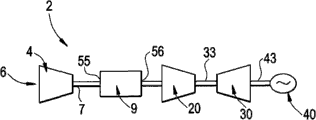
图1是根据本发明的示例性实施例的包括热管中间冷却器的涡轮机系统的示意图;以及
图2是根据本发明的示例性实施例的热管中间冷却器的部分剖开的透视图。
部件列表
| 2 | 涡轮机系统 |
| 4 | 第一压缩机 |
| 6 | 压缩机入口 |
| 7 | 压缩机出口 |
| 9 | 中间冷却器 |
| 20 | 第二压缩机 |
| 30 | 涡轮 |
| 33 | 压缩机/涡轮轴 |
| 40 | 发电机 |
| 43 | 涡轮/发电机轴 |
| 52 | 压力容器 |
| 53 | 主体 |
| 55 | 入口 |
| 56 | 出口 |
| 58 | 内部腔 |
| 60 | 支撑结构 |
| 66 | 热管 |
| 72 | 第一端部分 |
| 73 | 第二端部分 |
| 74 | 中间热交换器 |
| 77 | 第一热交换部分 |
| 78 | 第二热交换部分 |
| 84 | 风扇 |
具体实施方式
首先参考图1,根据本发明的示例性实施例的涡轮机系统总体地显示为2。涡轮机系统2包括具有压缩机入口6和压缩机出口7的压缩机4。如下文将更充分地论述,压缩机出口7流通地连接到中间冷却器9上。中间冷却器9构造成在压缩空气被引入第二压缩机20之前降低来自压缩机4的压缩空气的温度,第二压缩机20在压缩空气被输送至燃烧器(未示出)之前进一步地压缩空气。压缩机20经由压缩机/涡轮轴33操作地联接到涡轮30上。在显示的示例性实施例中,涡轮30通过涡轮/发电机轴43操作地联接到发电机40上。
现在参考图2,描述根据本发明的示例性实施例构建的中间冷却器9。如显示的,中间冷却器9包括主体53,其限定具有入口55、出口56和内部腔58的压力容器。中间冷却器9被显示为安置在支撑结构60上。根据所显示的示例性实施例,中间冷却器9包括都以66来表示的多个热管,此多个热管构造成从来自压缩机4的压缩气流中吸收热量。在此处应该理解,术语“热管”应解释成表示密封管或由具有高热导率的材料,诸如,但不限于,铜或铝制成的管。真空泵用于从密封管的内部排出所有流体(气体和液体两者),之后管被填充一部分体积的工作流体或冷却液,诸如,但不限于,水、乙醇、丙酮、钠或汞。部分真空接近或低于工作流体的蒸汽压力,使得一些流体为液相,一些为气相。
多个热管各包括延伸至内部腔58中的第一端部分72,其通向第二端部分73,第二端部分73布置在压力容器的外部,通过中间的或热交换区域74。热交换区域74实际上包括第一热交换部分77,例如,各热管66的位于内部腔58中的部分,和第二热交换部分78,例如,各热管66的位于内部腔58外的部分。通过此布置,压缩空气中附带的热量被第一热交换部分77吸收。热量迅速地通过中间区域74传导至第二热交换部分78。例如风扇84产生的对流气流,通过第二热交换部分78以去除热量。
在此处应该意识到,本发明的示例性实施例提供了一种简单的、有成本效益的从压缩气流中去除热量的系统。热管的使用提供了一种不需要大量水作为冷却液的易用、易维护和低成本的系统。同样地,本发明的示例性实施例允许涡轮对负荷变化响应更快。
大体上,此书面说明使用实例来公开发明,包括最佳模式,并且还使得任何本领域技术人员能够实施本发明,包括制作和使用任何装置或系统和执行任何结合在其中的方法。本发明的可取得专利的范围由权利要求限定,并且可包括本领域技术人员想到的其它实例。这样的其它实例将在本发明的示例性实施例的范围内,如果其具有不与权利要求的字面语言不同的结构元件,或者如果其包括与权利要求的字面语言无实质不同的等效的结构元件。
Claims (7)
1.一种涡轮机(2),包括:
包括入口部分(6)和出口部分(7)的压缩机(4),所述压缩机(4)压缩在所述入口部分(6)接收的空气以形成通过所述出口部分(7)的压缩气流;和
操作地连接到所述压缩机(4)的下游的中间冷却器(9),所述中间冷却器(9)包括多个构造成从所述压缩气流中吸收热量的热管(66)。
2.根据权利要求1所述的涡轮机(2),其特征在于,所述中间冷却器(9)包括压力容器(53),所述多个热管(66)各包括延伸至所述压力容器(53)中的第一端部分(72)和从所述压力容器(53)突出的第二端部分(73)。
3.根据权利要求2所述的涡轮机(2),其特征在于,还包括:至少一个对准所述中间冷却器(9)的风扇(84),所述至少一个风扇(84)引导强迫气流通过各所述多个热管(66)的所述第二端部分(73)。
4.根据权利要求1所述的涡轮机(2),其特征在于,所述多个热管(66)的至少一部分是包括至少是液相和气相中的一种的冷却液的密封热管。
5.根据权利要求1所述的涡轮机(2),其特征在于,所述多个热管(66)各包括外部表面和内部表面,所述多个热管(66)的至少一部分在内部表面上包括导热涂层。
6.根据权利要求1所述的涡轮机(2),其特征在于,还包括:布置在所述中间冷却器(9)下游的另一个压缩机(20),所述另一个压缩机(20)进一步地压缩通过所述中间冷却器(9)的所述压缩气流。
7.根据权利要求1所述的涡轮机,其特征在于,所述中间冷却器(9)不包括水作为冷却液。
Applications Claiming Priority (2)
| Application Number | Priority Date | Filing Date | Title |
|---|---|---|---|
| US12/181756 | 2008-07-29 | ||
| US12/181,756 US8157512B2 (en) | 2008-07-29 | 2008-07-29 | Heat pipe intercooler for a turbomachine |
Publications (1)
| Publication Number | Publication Date |
|---|---|
| CN101660452A true CN101660452A (zh) | 2010-03-03 |
Family
ID=41461835
Family Applications (1)
| Application Number | Title | Priority Date | Filing Date |
|---|---|---|---|
| CN200910165349A Pending CN101660452A (zh) | 2008-07-29 | 2009-07-29 | 用于涡轮机的热管中间冷却器 |
Country Status (4)
| Country | Link |
|---|---|
| US (1) | US8157512B2 (zh) |
| JP (1) | JP2010031866A (zh) |
| CN (1) | CN101660452A (zh) |
| DE (1) | DE102009026282A1 (zh) |
Cited By (2)
| Publication number | Priority date | Publication date | Assignee | Title |
|---|---|---|---|---|
| CN102345513A (zh) * | 2010-08-03 | 2012-02-08 | 通用电气公司 | 涡轮中间冷却器 |
| CN106285949A (zh) * | 2015-06-04 | 2017-01-04 | 中航商用航空发动机有限责任公司 | 发动机高压压气机出口冷却系统 |
Families Citing this family (6)
| Publication number | Priority date | Publication date | Assignee | Title |
|---|---|---|---|---|
| US10329940B2 (en) | 2013-10-04 | 2019-06-25 | General Electric Company | Method and system for passive clearance control in a gas turbine engine |
| US9963994B2 (en) | 2014-04-08 | 2018-05-08 | General Electric Company | Method and apparatus for clearance control utilizing fuel heating |
| US20160109193A1 (en) * | 2014-10-21 | 2016-04-21 | Greenergy Products, Inc. | Equipment and Method |
| US9797310B2 (en) | 2015-04-02 | 2017-10-24 | General Electric Company | Heat pipe temperature management system for a turbomachine |
| EP3277940B1 (en) | 2015-04-02 | 2019-10-23 | General Electric Company | Heat pipe temperature management system for wheels and buckets in a turbomachine |
| US10309242B2 (en) * | 2016-08-10 | 2019-06-04 | General Electric Company | Ceramic matrix composite component cooling |
Family Cites Families (52)
| Publication number | Priority date | Publication date | Assignee | Title |
|---|---|---|---|---|
| DE294483C (zh) | ||||
| US3517730A (en) | 1967-03-15 | 1970-06-30 | Us Navy | Controllable heat pipe |
| US3722797A (en) | 1970-11-04 | 1973-03-27 | Cci Aerospace Corp | Convergent divergent ejector exhaust nozzle |
| US4036290A (en) | 1972-01-24 | 1977-07-19 | Kelly Donald A | Helical expansion condenser |
| US3852805A (en) | 1973-06-18 | 1974-12-03 | Gen Electric | Heat-pipe cooled power semiconductor device assembly having integral semiconductor device evaporating surface unit |
| US4033406A (en) | 1974-09-03 | 1977-07-05 | Hughes Aircraft Company | Heat exchanger utilizing heat pipes |
| JPS5262757A (en) * | 1975-11-20 | 1977-05-24 | Tokico Ltd | Manufacturing of heat pipe |
| US4372110A (en) | 1976-02-13 | 1983-02-08 | Nasa | Noise suppressor for turbo fan jet engines |
| US4149588A (en) | 1976-03-15 | 1979-04-17 | Mcdonnell Douglas Corporation | Dry cooling system |
| US4621681A (en) | 1977-11-09 | 1986-11-11 | Q-Dot Corporation | Waste heat boiler |
| US4234782A (en) | 1978-01-19 | 1980-11-18 | Saskatchewan Power Corporation | Space heating using off-peak electric heat storage |
| US4226282A (en) | 1978-08-30 | 1980-10-07 | Foster Wheeler Energy Corporation | Heat exchange apparatus utilizing thermal siphon pipes |
| US4280554A (en) * | 1980-02-04 | 1981-07-28 | The Air Preheater Company, Inc. | Heat tube |
| US4426959A (en) | 1980-07-01 | 1984-01-24 | Q-Dot Corporation | Waste heat recovery system having thermal sleeve support for heat pipe |
| JPS5786600A (en) * | 1980-11-18 | 1982-05-29 | Setsuo Yamamoto | Gas compressor |
| US6866092B1 (en) * | 1981-02-19 | 2005-03-15 | Stephen Molivadas | Two-phase heat-transfer systems |
| US4381817A (en) | 1981-04-27 | 1983-05-03 | Foster Wheeler Energy Corporation | Wet/dry steam condenser |
| US4932204A (en) | 1989-04-03 | 1990-06-12 | Westinghouse Electric Corp. | Efficiency combined cycle power plant |
| US5233934A (en) | 1992-08-20 | 1993-08-10 | Wahlco Environmental Systems, Inc. | Control of NOx reduction in flue gas flows |
| US5237939A (en) | 1992-08-20 | 1993-08-24 | Wahlco Environmental Systems, Inc. | Method and apparatus for reducing NOx emissions |
| US5311930A (en) | 1992-11-17 | 1994-05-17 | Bruenn Paul R | Heat reclamation device |
| US5632143A (en) | 1994-06-14 | 1997-05-27 | Ormat Industries Ltd. | Gas turbine system and method using temperature control of the exhaust gas entering the heat recovery cycle by mixing with ambient air |
| DE19512466C1 (de) | 1995-04-03 | 1996-08-22 | Siemens Ag | Verfahren zum Betreiben eines Abhitzedampferzeugers sowie danach arbeitender Abhitzedampferzeuger |
| EP0794401A3 (en) | 1996-03-06 | 1998-09-23 | Hudson Products Corporation | Steam condensing apparatus |
| US5738024A (en) | 1996-04-19 | 1998-04-14 | Winegar; Phillip | Catalytic reduction apparatus for NOX reduction |
| EP0948430A4 (en) | 1996-10-25 | 2003-04-16 | Yuzhi Qu | SUPERCONDUCTING HEAT TRANSFER MEDIUM |
| US6916430B1 (en) | 1996-10-25 | 2005-07-12 | New Qu Energy Ltd. | Superconducting heat transfer medium |
| JPH1193694A (ja) | 1997-09-18 | 1999-04-06 | Toshiba Corp | ガスタービンプラント |
| JPH11153099A (ja) * | 1997-11-21 | 1999-06-08 | Copal Co Ltd | 冷却装置 |
| US6065280A (en) | 1998-04-08 | 2000-05-23 | General Electric Co. | Method of heating gas turbine fuel in a combined cycle power plant using multi-component flow mixtures |
| US6241009B1 (en) | 2000-02-07 | 2001-06-05 | Hudson Products Corporation | Integrated heat pipe vent condenser |
| US6397575B2 (en) | 2000-03-23 | 2002-06-04 | General Electric Company | Apparatus and methods of reheating gas turbine cooling steam and high pressure steam turbine exhaust in a combined cycle power generating system |
| EP1193373A1 (de) | 2000-09-29 | 2002-04-03 | Siemens Aktiengesellschaft | Verfahren zum Betreiben einer Gas- und Dampfturbinenanlage sowie entsprechende Anlage |
| US20030182944A1 (en) * | 2002-04-02 | 2003-10-02 | Hoffman John S. | Highly supercharged gas-turbine generating system |
| US7069716B1 (en) | 2002-04-24 | 2006-07-04 | Express Integrated Technologies Llc | Cooling air distribution apparatus |
| US6782703B2 (en) | 2002-09-11 | 2004-08-31 | Siemens Westinghouse Power Corporation | Apparatus for starting a combined cycle power plant |
| US6962051B2 (en) | 2003-06-17 | 2005-11-08 | Utc Power, Llc | Control of flow through a vapor generator |
| US7131294B2 (en) * | 2004-01-13 | 2006-11-07 | Tecumseh Products Company | Method and apparatus for control of carbon dioxide gas cooler pressure by use of a capillary tube |
| JP2006090156A (ja) * | 2004-09-21 | 2006-04-06 | Shin Caterpillar Mitsubishi Ltd | 廃熱エネルギ再生方法および廃熱エネルギ再生装置 |
| US20060083626A1 (en) * | 2004-10-19 | 2006-04-20 | Manole Dan M | Compressor and hermetic housing with minimal housing ports |
| JP2006284144A (ja) | 2005-04-04 | 2006-10-19 | Denso Corp | 排熱回収装置 |
| JP2006317013A (ja) | 2005-04-12 | 2006-11-24 | Denso Corp | ヒートパイプおよびそれを用いた排熱回収装置 |
| US20070017207A1 (en) | 2005-07-25 | 2007-01-25 | General Electric Company | Combined Cycle Power Plant |
| US20070234704A1 (en) * | 2005-09-01 | 2007-10-11 | General Electric Company | Methods and apparatus for operating gas turbine engines |
| US7730727B2 (en) | 2005-09-06 | 2010-06-08 | American Air Liquide, Inc. | Flexible flow control device for cogeneration ducting applications |
| US7523602B2 (en) | 2005-09-27 | 2009-04-28 | United Technologies Corporation | Turbine exhaust catalyst |
| EP1801241A1 (en) * | 2005-12-23 | 2007-06-27 | Paul Wurth S.A. | A rotary charging device for a shaft furnace equipped with a cooling system |
| US7382047B2 (en) | 2005-12-27 | 2008-06-03 | Fu Zhun Precision Industry (Shen Zhen) Co., Ltd. | Heat dissipation device |
| US7621720B2 (en) * | 2006-06-30 | 2009-11-24 | General Electric Company | Cooling device |
| US7784300B2 (en) * | 2006-12-22 | 2010-08-31 | Yiding Cao | Refrigerator |
| US20080164009A1 (en) | 2007-01-07 | 2008-07-10 | Yong Chong | Direct Embedded Heat Pipe Apparatus |
| US8359824B2 (en) | 2008-07-29 | 2013-01-29 | General Electric Company | Heat recovery steam generator for a combined cycle power plant |
-
2008
- 2008-07-29 US US12/181,756 patent/US8157512B2/en active Active
-
2009
- 2009-07-24 JP JP2009172617A patent/JP2010031866A/ja active Pending
- 2009-07-29 DE DE102009026282A patent/DE102009026282A1/de not_active Withdrawn
- 2009-07-29 CN CN200910165349A patent/CN101660452A/zh active Pending
Cited By (2)
| Publication number | Priority date | Publication date | Assignee | Title |
|---|---|---|---|---|
| CN102345513A (zh) * | 2010-08-03 | 2012-02-08 | 通用电气公司 | 涡轮中间冷却器 |
| CN106285949A (zh) * | 2015-06-04 | 2017-01-04 | 中航商用航空发动机有限责任公司 | 发动机高压压气机出口冷却系统 |
Also Published As
| Publication number | Publication date |
|---|---|
| US20100028140A1 (en) | 2010-02-04 |
| DE102009026282A1 (de) | 2010-02-04 |
| JP2010031866A (ja) | 2010-02-12 |
| US8157512B2 (en) | 2012-04-17 |
Similar Documents
| Publication | Publication Date | Title |
|---|---|---|
| CN101660452A (zh) | 用于涡轮机的热管中间冷却器 | |
| CN101660433A (zh) | 用于联合循环发电设备的热回收蒸汽锅炉 | |
| CN104353258B (zh) | 减顶抽真空系统及工艺 | |
| CN111577466A (zh) | 航空发动机防冰引气预热与涡轮冷却引气预冷系统 | |
| JP2010031866A5 (zh) | ||
| CN100381678C (zh) | 汽轮机乏汽回收系统 | |
| CN100504267C (zh) | 高温凝结水回收系统 | |
| CN106499519A (zh) | 具有级间冷却的lng燃气轮机 | |
| CN107044347B (zh) | 一种回热器和燃气轮机 | |
| CN108050093A (zh) | 一种排风热回收消音装置 | |
| CN101881189B (zh) | 蒸汽涡轮动力系统及其组装方法 | |
| CN206917855U (zh) | 水蒸气螺杆式压缩机组 | |
| CN207906077U (zh) | 自动集液罗茨螺杆真空机组 | |
| CN207018092U (zh) | 一种回热器和燃气轮机 | |
| CN206449944U (zh) | 一种补压式制冷装置 | |
| CN216048367U (zh) | 一种空气源热泵热水器用密封保护装置 | |
| CN206368814U (zh) | 一种两级气冷罗茨螺杆真空机组 | |
| CN100395483C (zh) | 多容器管路连接系统 | |
| CN204319802U (zh) | 减顶抽真空系统 | |
| CN110043465A (zh) | 一种节能型锥体真空泵机组 | |
| CN207750272U (zh) | 一种排风热回收消音装置 | |
| CN202110066U (zh) | 高温燃气升压及降温系统 | |
| CN107726878B (zh) | 自然通风直接空冷系统 | |
| CN207024669U (zh) | 一种减压塔顶蒸汽抽真空装置 | |
| CN212030264U (zh) | 节能高效的凝汽式机组真空抽取系统 |
Legal Events
| Date | Code | Title | Description |
|---|---|---|---|
| C06 | Publication | ||
| PB01 | Publication | ||
| C10 | Entry into substantive examination | ||
| SE01 | Entry into force of request for substantive examination | ||
| C02 | Deemed withdrawal of patent application after publication (patent law 2001) | ||
| WD01 | Invention patent application deemed withdrawn after publication |
Application publication date: 20100303 |