CN101346309A - Manufacturing method of polysilicon - Google Patents
Manufacturing method of polysilicon Download PDFInfo
- Publication number
- CN101346309A CN101346309A CNA2006800491740A CN200680049174A CN101346309A CN 101346309 A CN101346309 A CN 101346309A CN A2006800491740 A CNA2006800491740 A CN A2006800491740A CN 200680049174 A CN200680049174 A CN 200680049174A CN 101346309 A CN101346309 A CN 101346309A
- Authority
- CN
- China
- Prior art keywords
- gas
- temperature
- silicon
- chlorosilane
- container
- Prior art date
- Legal status (The legal status is an assumption and is not a legal conclusion. Google has not performed a legal analysis and makes no representation as to the accuracy of the status listed.)
- Pending
Links
Images


Classifications
-
- Y—GENERAL TAGGING OF NEW TECHNOLOGICAL DEVELOPMENTS; GENERAL TAGGING OF CROSS-SECTIONAL TECHNOLOGIES SPANNING OVER SEVERAL SECTIONS OF THE IPC; TECHNICAL SUBJECTS COVERED BY FORMER USPC CROSS-REFERENCE ART COLLECTIONS [XRACs] AND DIGESTS
- Y02—TECHNOLOGIES OR APPLICATIONS FOR MITIGATION OR ADAPTATION AGAINST CLIMATE CHANGE
- Y02P—CLIMATE CHANGE MITIGATION TECHNOLOGIES IN THE PRODUCTION OR PROCESSING OF GOODS
- Y02P70/00—Climate change mitigation technologies in the production process for final industrial or consumer products
- Y02P70/50—Manufacturing or production processes characterised by the final manufactured product
Landscapes
- Silicon Compounds (AREA)
Abstract
Description
技术领域 technical field
本发明涉及多晶硅的制造方法。The present invention relates to a method for producing polysilicon.
背景技术 Background technique
在环境问题的日益严重中,太阳能电池作为洁净能源备受注目,在我国以住宅用为中心的需要剧增。硅系太阳能电池由于可靠性或转换效率优异,因此占据了太阳光发电的8成左右,但是为了进一步增加需要、减少发电单价,希望确保低价格的硅原料。目前,高纯度硅的制造中厂家几乎均采用将三氯硅烷热分解的西门子法。但是,该方法的电力消耗率是有限制的,可以说进一步的成本降低是困难的。Amid increasingly serious environmental problems, solar cells are attracting attention as a clean energy source, and demand for them is increasing rapidly in Japan mainly for residential use. Silicon-based solar cells account for about 80% of solar power generation due to their excellent reliability and conversion efficiency. However, it is desired to secure low-cost silicon raw materials in order to further increase demand and reduce the unit price of power generation. At present, almost all manufacturers of high-purity silicon use the Siemens method of thermally decomposing trichlorosilane. However, the power consumption rate of this method is limited, and further cost reduction can be said to be difficult.
作为代替热分解的方法,提出了使用锌或铝将氯硅烷还原制造硅的方法。例如已知使微粒的铝与四氯化硅气体反应获得硅的方法。As a method instead of thermal decomposition, a method of producing silicon by reducing chlorosilane using zinc or aluminum has been proposed. For example, a method of obtaining silicon by reacting particulate aluminum with silicon tetrachloride gas is known.
日本特开平2-64006号公报(美国专利说明书4919913)公开了一种方法,其为使式SiHnX4-n(式中X为卤素、n为0~3的值。)所示的气体硅化合物与铝反应的硅制造方法,使微细分散有纯铝或Al-Si合金的熔融表面与气体的硅化合物相接触的方法。Japanese Patent Laid-Open Publication No. 2-64006 (U.S. Patent Specification 4919913) discloses a method for making the gas represented by the formula SiH n X 4-n (wherein X is a halogen and n is a value of 0 to 3.) A silicon production method in which a silicon compound reacts with aluminum is a method in which a molten surface finely dispersed with pure aluminum or an Al-Si alloy is brought into contact with a gaseous silicon compound.
日本特开平60-103016号公报公开了通过对在高温下向高浓度的硅合金、硅铜合金通入四氯化硅气体所产生的气体进行必要的冷却,仅使部分量的硅分解析出,从而使杂质吸附在该析出部分上,然后将该气体冷却,从而获得纯硅的精制方法。Japanese Patent Application Publication No. 60-103016 discloses that only part of the silicon is decomposed and separated by cooling the gas generated by introducing silicon tetrachloride gas into high-concentration silicon alloys and silicon-copper alloys at high temperatures. , so that impurities are adsorbed on the precipitated part, and then the gas is cooled to obtain pure silicon.
另外,日本特公昭36-8416号公报公开在高温下使铝蒸发、将四氯化硅还原的方法。In addition, Japanese Patent Publication No. Sho 36-8416 discloses a method of reducing silicon tetrachloride by evaporating aluminum at a high temperature.
发明内容 Contents of the invention
本发明的目的在于提供高效地用金属还原氯硅烷、制造高纯度的多晶硅的方法。An object of the present invention is to provide a method for efficiently reducing chlorosilanes with metals to produce high-purity polysilicon.
本发明人为了解决上述课题对多晶硅的制造方法进行深入研究,结果完成本发明。In order to solve the above-mentioned problems, the inventors of the present invention conducted intensive studies on a method for producing polycrystalline silicon, and as a result, completed the present invention.
即,本发明提供That is, the present invention provides
[1]具有工序(A)、(B)和(C)的多晶硅制造方法,[1] A polysilicon manufacturing method having steps (A), (B) and (C),
(A)在温度T1下用金属还原下式(1)所示的氯硅烷,获得硅化合物的工序、(A) A step of reducing a chlorosilane represented by the following formula (1) with a metal at a temperature T1 to obtain a silicon compound,
SiHnCl4-n (1)SiH n Cl 4-n (1)
(式中,n为0~3的整数)(where n is an integer from 0 to 3)
(B)将该硅化合物移送至温度T2(为T1>T2的关系)的部分的工序、(B) a step of transferring the silicon compound to a portion at a temperature T2 (the relationship of T1>T2),
(C)使多晶硅在该温度T2的部分析出的工序,这里,温度T1为金属熔点(绝对温度)的1.29倍以上、温度T2高于金属氯化物的升华点或沸点。(C) A step of separating polysilicon at the temperature T2, where the temperature T1 is 1.29 times or more the melting point (absolute temperature) of the metal, and the temperature T2 is higher than the sublimation point or boiling point of the metal chloride.
[2]多晶硅的制造方法,其还具有工序(D):[2] A method for producing polycrystalline silicon, further comprising a step (D):
(D)将工序(C)获得的多晶硅精制的工序。(D) A step of refining the polycrystalline silicon obtained in the step (C).
[3]上述[1]或[2]所述的方法,其中,原料为氯硅烷或者氯硅烷与惰性气体的混合气体。[3] The method according to [1] or [2] above, wherein the raw material is chlorosilane or a mixed gas of chlorosilane and inert gas.
[4]上述[3]所述的方法,其中,原料为氯硅烷浓度10体积%以上。[4] The method according to the above [3], wherein the raw material has a chlorosilane concentration of 10% by volume or more.
[5]上述[1]或[2]所述的方法,其中,氯硅烷为选自四氯化硅、三氯硅烷、二氯硅烷和一氯硅烷的至少一种。[5] The method according to [1] or [2] above, wherein the chlorosilane is at least one selected from the group consisting of silicon tetrachloride, trichlorosilane, dichlorosilane and monochlorosilane.
[6]上述[1]或[2]所述的方法,其中,金属为选自钾、铯、铷、锶、锂、钠、镁、铝、锌和锰的至少一种。[6] The method according to [1] or [2] above, wherein the metal is at least one selected from the group consisting of potassium, cesium, rubidium, strontium, lithium, sodium, magnesium, aluminum, zinc and manganese.
[7]上述[6]所述的方法,其中,金属为铝。[7] The method described in [6] above, wherein the metal is aluminum.
[8]上述[7]所述的方法,其中,铝为下式所示的纯度99.9重量%以上。[8] The method according to the above [7], wherein the aluminum has a purity of 99.9% by weight or more represented by the following formula.
纯度(重量%)=100-(Fe+Cu+Ga+Ti+Ni+Na+Mg+Zn)Purity (weight %)=100-(Fe+Cu+Ga+Ti+Ni+Na+Mg+Zn)
[式中,Fe、Cu、Ga、Ti、Ni、Na、Mg、Zn分别表示铁、铜、鎵、钛、镍、钠、镁、锌的含量(重量%)。][wherein, Fe, Cu, Ga, Ti, Ni, Na, Mg, and Zn represent the contents (% by weight) of iron, copper, gallium, titanium, nickel, sodium, magnesium, and zinc, respectively. ]
[9]上述[1]或[2]所述的方法,其中,温度T2部分的气体流速为0.62m/分钟以上、小于1000m/分钟。[9] The method according to [1] or [2] above, wherein the gas flow rate at the temperature T2 is 0.62 m/min to less than 1000 m/min.
[10]太阳能电池,其为具有通过上述[1]或[2]所述方法获得的多晶硅的太阳能电池。[10] A solar cell comprising polycrystalline silicon obtained by the method described in [1] or [2] above.
另外,本发明还提供具有(1)~(7)的装置。In addition, the present invention also provides devices having (1) to (7).
(1)用金属还原氯硅烷的反应容器、(1) Reaction container for reducing chlorosilane with metal,
(2)用于加热容器内气体的加热器、(2) Heaters for heating the gas in the container,
(3)向容器中导入氯硅烷作为原料的供给器、(3) A feeder for introducing chlorosilane into the container as a raw material,
(4)使多晶硅析出的析出容器、(4) a precipitation container for precipitation of polysilicon,
(5)将容器内产生的气体导入至析出部的移送器、(5) A transfer device that introduces the gas generated in the container to the precipitation part,
(6)调整向析出部移送的气体的流速来冷却气体的冷却器、以及(6) a cooler for cooling the gas by adjusting the flow velocity of the gas transferred to the precipitation part, and
(7)用于使容器内的气体温度T1为金属的熔点(绝对温度)的1.29倍以上、保温移送中的气体、且使析出部气体的温度T2高于金属氯化物的升华点或沸点的温度调节器。(7) Used to make the gas temperature T1 in the container more than 1.29 times the melting point (absolute temperature) of the metal, keep the gas being transported, and make the temperature T2 of the gas in the precipitation part higher than the sublimation point or boiling point of the metal chloride temperature regulator.
附图说明 Description of drawings
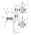
图1表示本发明装置的第一实施方式。Figure 1 shows a first embodiment of the device according to the invention.
图2表示本发明装置的第二实施方式。Figure 2 shows a second embodiment of the device according to the invention.
图3表示本发明装置的第三实施方式。Figure 3 shows a third embodiment of the device according to the invention.
图4表示本发明装置的第四实施方式。Figure 4 shows a fourth embodiment of the device according to the invention.
图5表示本发明装置的第五实施方式。Figure 5 shows a fifth embodiment of the device of the invention.
图6表示本发明装置的第六实施方式。Figure 6 shows a sixth embodiment of the device of the invention.
图7表示实施例1所用装置的概略图。FIG. 7 shows a schematic diagram of the apparatus used in Example 1. FIG.
图8为表示硅析出状态的照片。Fig. 8 is a photograph showing the state of silicon precipitation.
符号说明Symbol Description
1反应容器1 reaction vessel
2加热器2 heaters
3供给器3 feeders
4析出容器4 precipitation container
5移送器5 transfer device
6冷却器6 coolers
7温度调节器7 temperature regulator
11加热器(立式环状炉)11 heater (vertical annular furnace)
12供给管(气体导入管)12 supply pipe (gas introduction pipe)
13氧化铝容器主体13 alumina container body
14反应容器(氧化铝保护管)14 reaction vessel (alumina protection tube)
15熔融铝15 molten aluminum
16SiCl4/Ar、反应气体16SiCl 4 /Ar, reaction gas
171273K温度区域171273K temperature zone
18氧化铝容器盖18 aluminum oxide container lid
19773K温度区域19773K temperature zone
具体实施方式 Detailed ways
工序(A):还原Process (A): Reduction
本发明的多晶硅的制造方法具有上述工序(A)。工序(A)所用原料为上述式(1)所示的氯硅烷,四氯化硅、三氯硅烷、二氯硅烷、一氯硅烷。这些物质可以单独使用、或者组合使用。这些物质中,含有氢的物质(三氯硅烷、二氯硅烷、一氯硅烷)由于还原反应而产生氯化氢,因此会诱导反应炉材料或导管的腐蚀。从防止腐蚀的观点出发,氯硅烷优选为四氯化硅。氯硅烷的纯度由于杂质蓄积在还原所得的硅中的概率高,因此优选B、P小于1ppm,为99.99%以上。原料可以为上述氯硅烷、或者可以为氯硅烷和惰性气体的混合物。惰性气体例如有氮气、氩气、氦气、氖气,优选氩。原料为氯硅烷和惰性气体的混合气体时,混合气体中的氯硅烷浓度从反应效率高、短时间内提高硅的收率的观点出发,优选为10%体积以上。The manufacturing method of polycrystalline silicon of this invention has the said process (A). The raw materials used in the step (A) are chlorosilanes represented by the above formula (1), silicon tetrachloride, trichlorosilane, dichlorosilane, and monochlorosilane. These substances can be used alone or in combination. Among these substances, substances containing hydrogen (trichlorosilane, dichlorosilane, and monochlorosilane) generate hydrogen chloride due to a reduction reaction, thereby inducing corrosion of reactor materials or conduits. From the viewpoint of preventing corrosion, the chlorosilane is preferably silicon tetrachloride. The purity of chlorosilane is preferably less than 1 ppm for B and P, and is 99.99% or more because impurities are likely to accumulate in the reduced silicon. The raw material may be the above-mentioned chlorosilane, or may be a mixture of chlorosilane and an inert gas. Inert gases are, for example, nitrogen, argon, helium, neon, preferably argon. When the raw material is a mixed gas of chlorosilane and an inert gas, the concentration of chlorosilane in the mixed gas is preferably 10% by volume or more from the viewpoint of high reaction efficiency and improved silicon yield in a short time.
金属只要可以还原氯硅烷即可,在后述温度T1下,金属氯化物的生成自由能低于硅的生成自由能。另外,优选金属的熔点低于硅。这种金属例如为钾、铯、铷、锶、锂、钠、镁、铝、锌、锰,优选铝。这些物质可以单独或组合使用。铝即便残存在所生成的硅或其表面上,利用酸或碱的溶解除去或利用偏析法的除去也容易,不会腐蚀反应炉的构造构件。铝的纯度优选为99.9重量%以上。予以说明,本说明书中铝的纯度通过下式计算。The metal may be used as long as it can reduce chlorosilane, and the free energy of formation of metal chloride is lower than that of silicon at temperature T1 described later. In addition, it is preferable that the melting point of the metal is lower than that of silicon. Such metals are, for example, potassium, cesium, rubidium, strontium, lithium, sodium, magnesium, aluminium, zinc, manganese, preferably aluminium. These substances can be used alone or in combination. Even if aluminum remains on the formed silicon or its surface, it can be easily removed by dissolution or segregation with an acid or alkali, and does not corrode the structural members of the reaction furnace. The purity of aluminum is preferably 99.9% by weight or more. In addition, the purity of aluminum in this specification is calculated by the following formula.
纯度(重量%)=100-(Fe+Cu+Ga+Ti+Ni+Na+Mg+Zn)Purity (weight %)=100-(Fe+Cu+Ga+Ti+Ni+Na+Mg+Zn)
式中,Fe、Cu、Ga、Ti、Ni、Na、Mg、Zn分别表示铁、铜、鎵、钛、镍、钠、镁、锌的含量(重量%)。另外,铝优选硼含量为5ppm以下、磷含量为0.5ppm以下。In the formula, Fe, Cu, Ga, Ti, Ni, Na, Mg, and Zn represent the contents (% by weight) of iron, copper, gallium, titanium, nickel, sodium, magnesium, and zinc, respectively. In addition, aluminum preferably has a boron content of 5 ppm or less and a phosphorus content of 0.5 ppm or less.
还原可以在以下的温度T1、压力的条件下进行。The reduction can be performed under the following conditions of temperature T1 and pressure.
T1为金属熔点的1.29倍以上、优选为1.33倍以上、更优选为1.41倍以上,优选小于2.33倍、更优选小于2.11倍、特别优选小于1.90倍。T1小于熔点的1.29倍时,反应需要时间。为2.33倍以上时,没有耐受高温的装置,难以连续进行还原反应。金属为铝时,T1优选1204K以上小于2173K、更优选1241K以上小于1973K、特别优选1316K以上小于1773K。本说明书中,温度T1表示容器中的金属绝对温度。T1 is 1.29 times or more, preferably 1.33 times or more, more preferably 1.41 times or more, preferably less than 2.33 times, more preferably less than 2.11 times, particularly preferably less than 1.90 times the melting point of the metal. When T1 is less than 1.29 times the melting point, the reaction takes time. When it is 2.33 times or more, there is no high-temperature-resistant device, and it is difficult to continuously perform the reduction reaction. When the metal is aluminum, T1 is preferably not less than 1204K and less than 2173K, more preferably not less than 1241K and less than 1973K, particularly preferably not less than 1316K and less than 1773K. In this specification, the temperature T1 represents the absolute temperature of the metal in the container.
压力为0.5bar以上小于5.0bar。压力小于0.5bar时,有反应效率降低的倾向。另一方面,为5.0bar以上时,为了保持容器内的压力,装置结构大型化,变得复杂。The pressure is above 0.5bar and less than 5.0bar. When the pressure is less than 0.5 bar, the reaction efficiency tends to decrease. On the other hand, when it is 5.0 bar or more, in order to maintain the pressure in a container, an apparatus structure enlarges and becomes complicated.
还原例如可以通过向熔融的金属中吹入气化的氯硅烷的方法、向保持于金属熔点以上且硅熔点以下的温度的氯硅烷气氛中喷射金属的熔融微粉末(例如平均粒径200μm以下的粉末)的方法、向流化床投入金属微粉末接着流通氯硅烷加热至金属熔点以上温度的方法进行。For example, the reduction can be carried out by blowing gasified chlorosilane into molten metal, spraying molten fine powder of metal (for example, a particle with an average particle size of 200 μm or less) into a chlorosilane atmosphere maintained at a temperature above the melting point of the metal and below the melting point of silicon. Powder) method, the method of putting metal fine powder into the fluidized bed and then circulating chlorosilane to heat to a temperature above the melting point of the metal.
还原从装置构成简单、以低成本即可获得硅的方面出发,优选向熔融的金属中吹入气化的氯硅烷的方法。For the reduction, the method of blowing vaporized chlorosilane into the molten metal is preferable from the viewpoint of simple apparatus configuration and low-cost silicon obtainment.
工序(A)中,可以用金属还原氯硅烷(例如SiCl4),产生低卤化物(例如SiCl3或SiCl2)。In step (A), chlorosilanes (such as SiCl 4 ) can be reduced with metals to produce subhalides (such as SiCl 3 or SiCl 2 ).
越在高温下进行还原,越优先地发生硅的低卤化物化,因此从获得高纯度硅的观点出发,优选在高温下进行还原。所得低卤化物在后述析出部等低温部处变为硅和SiCl4。所得SiCl4可以作为原料再利用。The lower the halide of silicon occurs preferentially as the reduction is performed at a higher temperature, it is therefore preferable to perform the reduction at a higher temperature from the viewpoint of obtaining high-purity silicon. The obtained subhalide becomes silicon and SiCl 4 at a low temperature part such as a precipitation part which will be described later. The obtained SiCl 4 can be reused as a raw material.
工序(B):移送Process (B): Transfer
本发明的多晶硅制造方法具有上述工序(B)。工序(B)中,移送工序(A)获得的反应气体。移送可以通过在工序(A)进行还原的容器与后述工序(C)的析出部中产生压力差而实施,例如可以向容器中连续地供给作为原料的氯硅烷,将反应气体从容器送至析出部。The polycrystalline silicon manufacturing method of this invention has the said process (B). In the step (B), the reaction gas obtained in the step (A) is transferred. The transfer can be carried out by generating a pressure difference between the container for reduction in step (A) and the precipitation part of step (C) described later. For example, chlorosilane as a raw material can be continuously supplied to the container, and the reaction gas can be sent from the container to Precipitation Department.
另外,移送可以在容器与析出部之间设置用于进行气体移送的装置而进行。In addition, the transfer may be performed by providing a device for transferring the gas between the container and the precipitation unit.
工序(C):析出Step (C): Precipitation
本发明的多晶硅制造方法具有上述工序(C)。工序(C)中,从所移送的反应气体中析出硅。The polycrystalline silicon manufacturing method of this invention has the said process (C). In the step (C), silicon is deposited from the transferred reaction gas.
析出可以在以下的温度T2、气体流速的条件下进行。The precipitation can be carried out under the following conditions of temperature T2 and gas flow rate.
T2优选低于T1、另外高于金属氯化物的升华点或沸点,更优选为以绝对温度表示的金属氯化物升华点或沸点的1.5倍以上、特别优选为2倍以上。T2当高于金属氯化物的升华点或沸点时,由于氯化物和硅较少同时析出,因此并非必需将它们分离的工序。例如,金属为铝时,T2优选小于T1、高于453K,更优选680K以上、特别优选906K以上。T2 is preferably lower than T1, and higher than the sublimation point or boiling point of the metal chloride, more preferably 1.5 times or more, particularly preferably 2 times or more, the sublimation point or boiling point of the metal chloride expressed in absolute temperature. When T2 is higher than the sublimation point or boiling point of the metal chloride, since the chloride and silicon rarely precipitate at the same time, the step of separating them is not necessary. For example, when the metal is aluminum, T2 is preferably smaller than T1 and higher than 453K, more preferably 680K or higher, particularly preferably 906K or higher.
气体流速在将气体温度换算为T1时为0.62m/分钟以上小于1000m/分钟、优选为0.62m/分钟以上小于100m/分钟、更优选为1.0m/分钟以上小于20m/分钟。气体流速小于0.62m/分钟时,有硅的析出量降低的倾向。另外,为1000m/分钟以上时,硅的析出域增大、大容积的析出容器成为必要。The gas flow rate is 0.62 m/min to 1000 m/min, preferably 0.62 m/min to 100 m/min, more preferably 1.0 m/min to 20 m/min when the gas temperature is converted to T1. When the gas flow rate is less than 0.62 m/min, the deposited amount of silicon tends to decrease. In addition, when it is 1000 m/min or more, the deposition region of silicon increases, and a large-volume deposition container is required.
析出可以在硅的晶种存在下进行。在晶种存在下析出时,硅的析出域减小、可以将析出容器小型化。另外,析出可以以连续式、间歇式的任一种进行。例如,析出可以是在结晶上使硅析出的流化床方式;可以是准备2塔析出容器,交替进行在一个容器中析出、另一个容器中将硅取出的操作。Precipitation can be performed in the presence of silicon seed crystals. When the deposition is performed in the presence of a seed crystal, the deposition region of silicon is reduced, and the deposition container can be miniaturized. In addition, precipitation may be performed either continuously or batchwise. For example, the precipitation may be a fluidized bed method in which silicon is deposited on crystallization; two precipitation containers are prepared, and the operation of precipitating in one container and taking out silicon in the other container is alternately performed.
本发明的制造方法通常分别将与金属反应作为副产物产生的金属氯化物和未反应的氯硅烷气体回收。氯硅烷气体还可以作为原料再利用。In the production method of the present invention, metal chloride and unreacted chlorosilane gas produced as by-products by reacting with metals are usually recovered separately. Chlorosilane gas can also be reused as a raw material.
工序(D):精制Process (D): Refining
本发明的多晶硅制造方法还可以具有工序(D)。The method for producing polycrystalline silicon of the present invention may further include a step (D).
(D)将上述工序(C)获得的多晶硅精制的工序。(D) A step of refining the polycrystalline silicon obtained in the above step (C).
精制例如可以通过利用酸或碱的处理、定向凝固等的偏析、在高真空化下的溶解进行,优选利用定向凝固进行。这些方法可以单独进行或组合进行。通过这种精制,多晶硅所含的杂质元素进一步被减少。Purification can be performed, for example, by treatment with an acid or alkali, segregation such as directional solidification, or dissolution under high vacuum, preferably by directional solidification. These methods can be performed alone or in combination. Through this refining, the impurity elements contained in polysilicon are further reduced.
如此获得的多晶硅为高纯度,适用于太阳能电池用硅的原料。以下说明使用多晶硅的太阳能电池的制造方法。The polysilicon thus obtained is of high purity and is suitable as a raw material for silicon for solar cells. A method of manufacturing a solar cell using polycrystalline silicon will be described below.
利用铸造法或电磁铸造法由多晶硅获得锭。锭通常利用内周刃切断等切片,使用游离磨粒将两面抛光。所得圆板为了除去损坏层而浸渍于蚀刻液(例如氟酸),获得多晶基板。另外,多晶基板为了减少表面的光反射损失,可以使用切片机机械性地形成V槽,还可以利用反应性离子蚀刻或使用酸的各向同向性蚀刻形成纹理结构。基板的导电型一般为p型,因此例如可以通过添加硼或使铝残存而导入p型掺杂剂。通过在受光面上形成n型掺杂剂(例如磷、砷)的扩散层,获得p-n结。可以在基板的表面上形成氧化膜层(例如TiO2),在各面上形成电极。而且,还可以形成用于减少反射所导致的光能损失的防反射膜(例如MgF2),制作太阳能电池单元。Ingots are obtained from polycrystalline silicon by casting or electromagnetic casting. The ingot is usually sliced by cutting with an inner peripheral edge, and both sides are polished with free abrasive grains. The obtained disc is immersed in an etching solution (for example, hydrofluoric acid) in order to remove the damaged layer, and a polycrystalline substrate is obtained. In addition, in order to reduce the light reflection loss on the surface of the polycrystalline substrate, V-grooves can be formed mechanically using a slicer, and a texture structure can also be formed by reactive ion etching or isotropic etching using acid. Since the conductivity type of the substrate is generally p-type, a p-type dopant can be introduced, for example, by adding boron or leaving aluminum. A pn junction is obtained by forming a diffused layer of n-type dopants (such as phosphorus, arsenic) on the light receiving surface. An oxide film layer (such as TiO 2 ) can be formed on the surface of the substrate, and electrodes can be formed on each surface. Furthermore, an anti-reflection film (such as MgF 2 ) for reducing loss of light energy due to reflection can also be formed to produce a solar cell.
多晶硅的制造装置Polysilicon Manufacturing Equipment
本发明的装置具有反应容器1、加热器2、供给器3、析出容器4、移送器5、冷却器6和温度调节器7。The apparatus of the present invention has a
反应容器1只要可以进行用钾、铯、铷、锶、锂、钠、镁、铝、锌和锰等金属将上述式(1)所示氯硅烷还原的方法即可。反应容器1由温度T1下基本不与金属反应的材料构成,例如由二氧化硅、氧化铝、二氧化锆、二氧化钛、氧化锌、氧化镁、氧化锡等氧化物;氮化硅、氮化铝等氮化物;碳化硅等碳化物构成。这些物质的构成元素的一部分还可以被其它元素部分置换,例如可以是含有硅、铝、氧和氮的赛伦(Silon)或石墨、用300μm以下厚度的碳化硅或氮化硅将表面涂覆的材料。The
反应容器1可以在其内部具有保持金属的多孔板。多孔板的孔径只要是高温下熔融的金属利用其表面张力不会从多孔板中泄露的大小即可。The
加热器2只要是加热反应容器1内的金属、气体的即可,将反应容器1内的气体温度保持在金属熔点(绝对温度)的1.29倍以上。加热器2可以是加热反应容器1内的金属、气体的加热器,还可以是通过仅加热作为原料供给的氯硅烷将反应容器1内加热的加热器。The
供给器3只要是向反应容器1内导入氯硅烷作为原料的即可,例如为导管。供给器3还可以设置在反应容器1的侧面,还可以供给至反应容器1内作为原料的金属上。供给器3例如由有机硅、氧化铝、氧化锆、氧化钛、氧化锌、氧化镁、氧化锡等氧化物;氮化硅、氮化铝等氮化物;碳化硅等碳化物构成。这些物质的构成元素的一部分可以被其它元素部分取代,例如可以是含有硅、铝、氧和氮的赛伦或石墨、用300μm以下厚度的碳化硅或氮化硅将表面涂覆的材料。The
析出容器4可以用于使多晶硅析出。析出容器4由在温度T2下基本不与硅反应的材料构成,例如由有机硅、氧化铝、氧化锆、氧化钛、氧化锌、氧化镁、氧化锡等氧化物;氮化硅、氮化铝等氮化物;碳化硅等碳化物构成。这些物质的构成元素的一部分可以被其它元素部分取代,例如可以是含有硅、铝、氧和氮的赛伦或石墨、用300μm以下厚度的碳化硅或氮化硅将表面涂覆的材料。The
移送器5只要是能够将反应容器1内产生的气体移送至析出容器4即可。移送器5例如为连接反应容器1和析出容器4的导管、在反应容器1的内空间和析出容器4的内空间产生压力差的装置、设置在反应容器1和析出容器4之间(例如导管)的压力调整阀、为了调整气体流速而改变导管径的渐缩管。这些装置可以单独或组合使用。The
冷却器6只要是调整析出容器4内的气体流速、将气体冷却、使硅析出的装置即可。例如为陶瓷滤器。The
温度调节器7为用于使反应容器1内气体温度T1为金属熔点(绝对温度)的1.29倍以上、优选1.33倍以上,更优选1.41倍以上,优选小于2.33倍,更优选小于2.11倍,特别优选小于1.90倍,对移送中的气体进行保温,且使析出容器4的温度T2高于金属氯化物的升华点或沸点的装置。The
通过该装置,可以简单地进行例如上述多晶硅的制造方法的工序(A)、(B)和(C)。With this apparatus, for example, steps (A), (B) and (C) of the above-mentioned method for producing polycrystalline silicon can be easily performed.
接着,通过图1说明装置1的实施方式。Next, an embodiment of the
图1所示装置中,反应容器1和析出容器4通过移送器5而连接。将供给器3连接于反应容器1,在容器1、4和移送器5的外部设置加热器2。在析出容器4的内部设置冷却器6。加热器2利用温度调节器对各个部分进行控制。图1省略了在将反应气体从反应容器1移送至析出容器4的移送器5中产生反应容器1内空间和析出容器4内空间的压力差的装置(例如吹风机)。In the apparatus shown in FIG. 1 , the
使用图1所示装置,制造多晶硅时,将金属放入反应容器1内,将氯硅烷从供给器3导入至反应容器1。在反应容器1内金属与氯硅烷在温度T1下反应,所产生的反应气体经由移送器5被导入至析出容器4。反应气体在冷却器6内被冷却至温度T2,在析出容器4内硅从反应气体中析出。When polycrystalline silicon is produced using the apparatus shown in FIG. 1 , metal is placed in
图2所示装置除了将供给器3从反应容器3上面插入内部之外,具有与图1所示装置相同的结构。氯硅烷从供给器3的上方被移送至下方,与通过加热器2加热的金属相接触。氯硅烷被金属还原,产生反应气体。氯硅烷气体通过经过被加热的供给器3而被加热。The apparatus shown in FIG. 2 has the same structure as that shown in FIG. 1 except that the
图3所示的装置具有立式结构,在反应容器1的上方一侧具有析出容器4,它们通过移送器5连接。与图1所示装置同样,供给器3连接于反应容器1,在容器1、4和移送器5的外部设置加热器2。析出容器4的内部设有冷却器6。加热器2、移送器5、冷却器6分别通过温度调节器7根据金属、氯硅烷的种类调节至规定的气体温度和析出温度。The apparatus shown in FIG. 3 has a vertical structure, and has a
图4所示装置中,反应容器1、移送器5、析出容器4具有同一截面,它们被一体化。使用图4所示装置制造多晶硅时,在反应容器1内放入金属,将氯硅烷从供给器3的上方移送至下方,与通过加热器2加热的金属相接触。在反应容器1内金属与氯硅烷在温度T1下反应,所产生的反应气体经由移送器5被导入至析出容器4。反应气体例如使用供给器的外壁或移送器的内壁通过热交换被冷却,另外,使用冷却器(未图示)从外部进行冷却,在析出容器4内在温度T2下硅从反应气体析出。In the apparatus shown in FIG. 4 , the
图5所示装置为以流化床方式进行析出的装置,除了供给器3、析出容器4、冷却器6之外,具有与图1所示装置相同的结构。图5所示装置中,来自反应容器1的反应气体在移送器5内被调整温度,导入至析出容器4内。通过冷却,降低反应气体的温度,使得硅在晶种上析出。设置在反应容器1上部的供给器3用于调整析出容器4内的氯硅烷浓度。析出容器4内,晶种处于流动状态,硅析出在晶种上。The apparatus shown in FIG. 5 is an apparatus for performing precipitation in a fluidized bed system, and has the same structure as that of the apparatus shown in FIG. 1 except for a
图6所示装置除了图1所示装置之外还有供给器3、析出容器4、冷却器6。设置在反应容器1上部的供给器3用于调整析出容器4内的氯硅烷浓度。2个析出容器4通过设置在移送器5的阀可以交替工作。使用该装置可以在其中一个内进行析出时、在另一个内将析出的硅取出,能够连续地制造硅。The apparatus shown in FIG. 6 includes a
实施例Example
通过实施例说明本发明。但是,本发明并非限定于此。予以说明,铝和硅的组成分析通过辉光放电质谱法(GDMS)进行。The invention is illustrated by the examples. However, the present invention is not limited thereto. In addition, the compositional analysis of aluminum and silicon was performed by the glow discharge mass spectrometry (GDMS).
实施例1Example 1
使用图7所示装置进行。This was done using the device shown in Figure 7.
将放入有10g铝(纯度:99.999重量%、Fe 0.73ppm、Cu 1.9ppm、Ga 0.57ppm、Ti 0.03ppm、Ni 0.02ppm、Na 0.02ppm、Mg 0.45ppm、Zn小于0.05、B 0.05ppm、P0.27ppm)的氧化铝保护管14(ニッカト-制SSA-S、No.8内径13mm)保持在氧化铝容器13中,保持于立式环状炉11中。在1573K(铝熔点的1.68倍)下,将四氯化硅气体(纯度:99.9999重量%、Fe 5.2ppb、Al 0.8ppb、Cu 0.9ppb、Mg 0.8ppb、Ca 5.5ppb、P小于1ppm、B小于1ppm,トリケミカル研究所制)导入熔融铝中4小时,使其反应。为了起气泡,气体导入管12(ニッカト一制、SSA-S、外径6mm、内径4mm)的前端与氧化铝保护管14底部的距离为10mm。10g of aluminum (purity: 99.999% by weight, Fe 0.73ppm, Cu 1.9ppm, Ga 0.57ppm, Ti 0.03ppm, Ni 0.02ppm, Na 0.02ppm, Mg 0.45ppm, Zn less than 0.05, B 0.05ppm, P0 27ppm) alumina protection tube 14 (SSA-S manufactured by Nikkato, No. 8 with an inner diameter of 13 mm) is held in an alumina container 13 and held in a vertical annular furnace 11. At 1573K (1.68 times the melting point of aluminum), silicon tetrachloride gas (purity: 99.9999% by weight, Fe 5.2ppb, Al 0.8ppb, Cu 0.9ppb, Mg 0.8ppb, Ca 5.5ppb, P less than 1ppm, B less than 1 ppm, manufactured by Tri Chemical Research Institute) was introduced into the molten aluminum for 4 hours and allowed to react. The distance between the front end of the gas introduction tube 12 (manufactured by Nikkato, SSA-S, 6 mm in outer diameter and 4 mm in inner diameter) and the bottom of the alumina protection tube 14 was 10 mm for generating bubbles.
四氯化硅的移送为在0.1MPa下供给氩气(ジャパンェァガシズ制、纯度:99.9995%)作为载气而进行。向填充有四氯化硅气体的不锈钢制容器(未图示)内流入200SCCM的氩气(流量200mL/min、0℃、101.3kPa)作为载气。将蒸发获得的气体与载气一起导入氧化铝保护管14。每分钟的四氯化硅的供给量为0.476g。四氯化硅的供给摩尔数相对于铝的摩尔数为0.8%。不锈钢制容器保持在29℃的恒温槽中。同温度下的四氯化硅的蒸汽压为264mmHg,因此导入至氧化铝保护管14的四氯化硅气体的浓度为34.7体积%。The transfer of silicon tetrachloride was performed by supplying argon gas (manufactured by Japan Gashes, purity: 99.9995%) as a carrier gas at 0.1 MPa. Into a stainless steel container (not shown) filled with silicon tetrachloride gas, 200 SCCM of argon gas (flow rate: 200 mL/min, 0° C., 101.3 kPa) was flowed as a carrier gas. The evaporated gas is introduced into the alumina protection tube 14 together with the carrier gas. The supply amount of silicon tetrachloride per minute was 0.476 g. The supplied mole number of silicon tetrachloride was 0.8% with respect to the mole number of aluminum. The stainless steel container was kept in a constant temperature bath at 29°C. The vapor pressure of silicon tetrachloride at the same temperature is 264 mmHg, so the concentration of silicon tetrachloride gas introduced into the alumina protection tube 14 is 34.7% by volume.
通过流动4小时四氯化硅气体,将立式环状炉11冷却,取出氧化铝保护管14。氧化铝保护管14的内壁中,加热中、硅在900℃以下的温度区域部分上析出。将析出在气体导入管12外壁上的硅的照片示于图8中。The vertical annular furnace 11 was cooled by flowing silicon tetrachloride gas for 4 hours, and the alumina protection tube 14 was taken out. In the inner wall of the alumina protection tube 14, during heating, silicon is deposited in a temperature region of 900° C. or lower. A photograph of silicon deposited on the outer wall of the gas introduction pipe 12 is shown in FIG. 8 .
析出在氧化铝保护管14内壁的硅的重量为3.5g。The weight of silicon precipitated on the inner wall of the alumina protection tube 14 was 3.5 g.
实施例2Example 2
将放入有11g铝的氧化铝保护管14保持在氧化铝容器13中,保持于立式环状炉1中。在1573K下,将四氯化硅气体导入熔融铝中126分钟,在大气压下使其反应。The alumina protection tube 14 containing 11 g of aluminum was held in the alumina container 13 and held in the
向填充有四氯化硅气体的不锈钢制容器中流入50SCCM的氩气(流量50mL/min、0℃、101.3kPa)作为载气。将蒸发获得的气体与载气一起导入反应炉。每分钟的四氯化硅的供给量为0.44g。四氯化硅的供给摩尔数相对于铝的摩尔数为0.69%。与铝相接触成为同等温度的气体成分在析出部的流速为3.58m/min。将填充有四氯化硅的不锈钢制容器保持在45℃的恒温槽中。45℃下的四氯化硅的蒸汽压为500mmHg,四氯化硅气体的浓度为65.8体积%。除此之外进行与实施例1相同的操作。析出在氧化铝保护管14内壁的硅的重量为2.3g。Into a stainless steel container filled with silicon tetrachloride gas, 50 SCCM of argon gas (flow rate: 50 mL/min, 0° C., 101.3 kPa) was flowed as a carrier gas. The evaporated gas is introduced into the reaction furnace together with the carrier gas. The supply amount of silicon tetrachloride per minute was 0.44 g. The supplied mole number of silicon tetrachloride was 0.69% with respect to the mole number of aluminum. The flow velocity of the gas component in contact with the aluminum phase at the same temperature in the precipitation part was 3.58 m/min. The stainless steel container filled with silicon tetrachloride was kept in a 45 degreeC thermostat. The vapor pressure of silicon tetrachloride at 45° C. is 500 mmHg, and the concentration of silicon tetrachloride gas is 65.8% by volume. Other than that, the same operations as in Example 1 were performed. The weight of silicon precipitated on the inner wall of the alumina protection tube 14 was 2.3 g.
实施例3Example 3
在1473K(铝熔点的1.58倍)下,将四氯化硅气体导入熔融铝中126分钟,使其反应。析出部处的气体流速为3.36m/min。除此之外进行与实施例2相同的操作。析出在氧化铝保护管壁的硅的重量为1.2g。At 1473K (1.58 times the melting point of aluminum), silicon tetrachloride gas was introduced into molten aluminum for 126 minutes to allow it to react. The gas flow velocity at the precipitation part was 3.36 m/min. Other than that, the same operations as in Example 2 were performed. The weight of silicon precipitated on the wall of the alumina protection tube was 1.2 g.
实施例4Example 4
在氧化铝容器13A(ニッカト一制SSA-S、管、内径22mm)中放入距离氧化铝保护管14(ニッカト一制SSA-S、No.9、内径16mm)封闭端剪切100mm的构件14A和7个用同径的管剪切为长度30mm的构件14B,制作制造装置。在还原试验后,预先测定析出部的温度,由管的重量变化研究硅的析出量。在构件14A中投入11g的铝,在1573K(铝熔点的1.68倍)下将四氯化硅气体导入熔融铝中33分钟,在大气压下使其反应。为了起气泡,气体导入管12的前端与氧化铝保护管14A底部的距离为5mm。A member 14A cut 100 mm from the closed end of the alumina protection tube 14 (SSA-S, No. 9, inner diameter 16 mm manufactured by Nikkato) was placed in an alumina container 13A (SSA-S manufactured by Nikkato, tube, inner diameter 22 mm). Cut the members 14B with a length of 30 mm from seven pipes of the same diameter to manufacture a manufacturing device. After the reduction test, the temperature of the precipitation part was measured in advance, and the amount of silicon precipitation was studied from the weight change of the tube. 11 g of aluminum was put into the member 14A, and silicon tetrachloride gas was introduced into the molten aluminum at 1573 K (1.68 times the melting point of aluminum) for 33 minutes to react under atmospheric pressure. The distance between the front end of the gas introduction pipe 12 and the bottom of the alumina protection pipe 14A was 5 mm for bubbling.
向四氯化硅气体容器中流入94SCCM的氩气作为载气,随载气一起导入反应炉。每分钟的四氯化硅的供给量为0.82g。四氯化硅的供给摩尔数相对于铝的摩尔数为1.2%。与铝相接触变为同等温度的气体成分在析出部处的流速为6.74m/min。Flow 94 SCCM of argon into the silicon tetrachloride gas container as a carrier gas, and introduce it into the reaction furnace together with the carrier gas. The supply amount of silicon tetrachloride per minute was 0.82 g. The supplied mole number of silicon tetrachloride was 1.2% with respect to the mole number of aluminum. The flow velocity of the gas component at the precipitation part that has reached the same temperature in contact with the aluminum phase was 6.74 m/min.
填充有四氯化硅的不锈钢制容器保持在45℃的恒温槽中。45℃下的四氯化硅的蒸汽压为500mmHg,四氯化硅气体的浓度为66体积%。析出在氧化铝保护管壁和气体导入管的硅的重量为1.1g。硅中Fe为1.3ppm、Cu小于0.05ppm、Al为37ppm、P小于0.01ppm、B小于0.01ppm。The stainless steel container filled with silicon tetrachloride was kept in a 45 degreeC thermostat. The vapor pressure of silicon tetrachloride at 45° C. is 500 mmHg, and the concentration of silicon tetrachloride gas is 66% by volume. The weight of silicon precipitated on the wall of the alumina protection tube and the gas introduction tube was 1.1 g. Fe in silicon is 1.3ppm, Cu is less than 0.05ppm, Al is 37ppm, P is less than 0.01ppm, and B is less than 0.01ppm.
实施例5Example 5
向四氯化硅气体容器中流入179SCCM的氩气作为载气33分钟,随载气一起导入反应炉。每分钟的四氯化硅的供给量为1.55g。析出部处的气体流速为12.78m/min。除此之外,进行与实施例4相同的操作。Flow 179 SCCM of argon gas into the silicon tetrachloride gas container as a carrier gas for 33 minutes, and introduce it into the reaction furnace together with the carrier gas. The supply amount of silicon tetrachloride per minute was 1.55 g. The gas flow velocity at the precipitation part was 12.78 m/min. Other than that, the same operations as in Example 4 were performed.
析出在氧化铝保护管壁和气体导入管的硅的重量为2.2g。The weight of silicon precipitated on the walls of the alumina protection tube and the gas introduction tube was 2.2 g.
比较例1Comparative example 1
将立式环状炉11中的温度保持在1173K(铝熔点的1.26倍),在1173K下向熔融铝中导入四氯化硅气体,除此之外,进行与实施例1相同的操作。The same operation as in Example 1 was performed except that the temperature in the vertical annular furnace 11 was kept at 1173K (1.26 times the melting point of aluminum), and silicon tetrachloride gas was introduced into the molten aluminum at 1173K.
硅没有析出在氧化铝保护管14内壁上。Silicon does not precipitate on the inner wall of the alumina protection tube 14 .
通过将实施例所得的硅定向凝固,可以进一步减少硅中所含的杂质元素。该硅作为太阳能电池用的原料优选。The impurity elements contained in the silicon can be further reduced by directional solidifying the silicon obtained in the examples. This silicon is preferable as a raw material for solar cells.
产业实用性Industrial applicability
通过本发明的制造方法,氯硅烷和铝的反应性高、一次反应而得的硅作为硅化合物气体化、之后析出,因此可以高收率获得高纯度的多晶硅。According to the production method of the present invention, the reactivity between chlorosilane and aluminum is high, and silicon obtained by the primary reaction is gasified as a silicon compound and subsequently precipitated, so that high-purity polysilicon can be obtained at a high yield.
Claims (11)
Applications Claiming Priority (3)
| Application Number | Priority Date | Filing Date | Title |
|---|---|---|---|
| JP374252/2005 | 2005-12-27 | ||
| JP2005374252 | 2005-12-27 | ||
| JP147729/2006 | 2006-05-29 |
Publications (1)
| Publication Number | Publication Date |
|---|---|
| CN101346309A true CN101346309A (en) | 2009-01-14 |
Family
ID=40247943
Family Applications (1)
| Application Number | Title | Priority Date | Filing Date |
|---|---|---|---|
| CNA2006800491740A Pending CN101346309A (en) | 2005-12-27 | 2006-12-26 | Manufacturing method of polysilicon |
Country Status (1)
| Country | Link |
|---|---|
| CN (1) | CN101346309A (en) |
-
2006
- 2006-12-26 CN CNA2006800491740A patent/CN101346309A/en active Pending
Similar Documents
| Publication | Publication Date | Title |
|---|---|---|
| CN100550303C (en) | III nitride crystal and preparation method thereof | |
| US5961944A (en) | Process and apparatus for manufacturing polycrystalline silicon, and process for manufacturing silicon wafer for solar cell | |
| JP3865033B2 (en) | Continuous production method and continuous production apparatus for silicon oxide powder | |
| JP5311930B2 (en) | Method for producing silicon | |
| US20090202415A1 (en) | Process for producing high-purity silicon and apparatus | |
| EP0869102B1 (en) | Process and apparatus for preparing polycrystalline silicon and process for preparing silicon substrate for solar cell | |
| JP4038110B2 (en) | Method for producing silicon | |
| TW200804633A (en) | Plasma deposition apparatus and method for making polycrystalline silicon | |
| CN102947025B (en) | The manufacture of single-crystal semiconductor material | |
| US20120171848A1 (en) | Method and System for Manufacturing Silicon and Silicon Carbide | |
| US8173094B2 (en) | Method for producing polycrystalline silicon | |
| JP4692247B2 (en) | Method for producing high-purity polycrystalline silicon | |
| JP2004210594A (en) | Method of manufacturing high purity silicon | |
| JP5217162B2 (en) | Method for producing polycrystalline silicon | |
| JP4295823B2 (en) | Method for reducing and purifying high-purity metal from vaporizable metal compound by magnetron capacitively coupled plasma and apparatus therefor | |
| JP2004035382A (en) | Method of manufacturing polycrystalline silicon | |
| CN101346309A (en) | Manufacturing method of polysilicon | |
| JP2004099421A (en) | Method for manufacturing silicon | |
| CN102325722A (en) | Method and apparatus for producing chlorosilanes | |
| JP4692324B2 (en) | High purity polycrystalline silicon production equipment | |
| JP2007055891A (en) | Method for producing polycrystalline silicon | |
| WO2007013644A1 (en) | Process for producing polycrystalline silicon | |
| CA2211028C (en) | Process and apparatus for manufacturing polycrystalline silicon, and process for manufacturing silicon wafer for solar cell | |
| JP5383573B2 (en) | Reactor for producing polycrystalline silicon and method for producing polycrystalline silicon using the same | |
| JPS59121109A (en) | Production of high purity silicon |
Legal Events
| Date | Code | Title | Description |
|---|---|---|---|
| C06 | Publication | ||
| PB01 | Publication | ||
| C10 | Entry into substantive examination | ||
| SE01 | Entry into force of request for substantive examination | ||
| C12 | Rejection of a patent application after its publication | ||
| RJ01 | Rejection of invention patent application after publication |
Application publication date: 20090114 |