CN1011739B - Optical element for optical fibre transmission system - Google Patents
Optical element for optical fibre transmission systemInfo
- Publication number
- CN1011739B CN1011739B CN89101841A CN89101841A CN1011739B CN 1011739 B CN1011739 B CN 1011739B CN 89101841 A CN89101841 A CN 89101841A CN 89101841 A CN89101841 A CN 89101841A CN 1011739 B CN1011739 B CN 1011739B
- Authority
- CN
- China
- Prior art keywords
- optical element
- guide
- optical
- adjustable plate
- plate
- Prior art date
- Legal status (The legal status is an assumption and is not a legal conclusion. Google has not performed a legal analysis and makes no representation as to the accuracy of the status listed.)
- Expired
Links
Images

Classifications
-
- H—ELECTRICITY
- H04—ELECTRIC COMMUNICATION TECHNIQUE
- H04B—TRANSMISSION
- H04B10/00—Transmission systems employing electromagnetic waves other than radio-waves, e.g. infrared, visible or ultraviolet light, or employing corpuscular radiation, e.g. quantum communication
-
- G—PHYSICS
- G02—OPTICS
- G02B—OPTICAL ELEMENTS, SYSTEMS OR APPARATUS
- G02B6/00—Light guides; Structural details of arrangements comprising light guides and other optical elements, e.g. couplings
- G02B6/24—Coupling light guides
- G02B6/26—Optical coupling means
- G02B6/35—Optical coupling means having switching means
- G02B6/3564—Mechanical details of the actuation mechanism associated with the moving element or mounting mechanism details
- G02B6/3568—Mechanical details of the actuation mechanism associated with the moving element or mounting mechanism details characterised by the actuating force
- G02B6/357—Electrostatic force
-
- G—PHYSICS
- G02—OPTICS
- G02B—OPTICAL ELEMENTS, SYSTEMS OR APPARATUS
- G02B26/00—Optical devices or arrangements for the control of light using movable or deformable optical elements
- G02B26/02—Optical devices or arrangements for the control of light using movable or deformable optical elements for controlling the intensity of light
-
- G—PHYSICS
- G02—OPTICS
- G02B—OPTICAL ELEMENTS, SYSTEMS OR APPARATUS
- G02B26/00—Optical devices or arrangements for the control of light using movable or deformable optical elements
- G02B26/08—Optical devices or arrangements for the control of light using movable or deformable optical elements for controlling the direction of light
- G02B26/0875—Optical devices or arrangements for the control of light using movable or deformable optical elements for controlling the direction of light by means of one or more refracting elements
-
- G—PHYSICS
- G02—OPTICS
- G02B—OPTICAL ELEMENTS, SYSTEMS OR APPARATUS
- G02B6/00—Light guides; Structural details of arrangements comprising light guides and other optical elements, e.g. couplings
- G02B6/24—Coupling light guides
- G02B6/26—Optical coupling means
- G02B6/264—Optical coupling means with optical elements between opposed fibre ends which perform a function other than beam splitting
- G02B6/266—Optical coupling means with optical elements between opposed fibre ends which perform a function other than beam splitting the optical element being an attenuator
-
- G—PHYSICS
- G02—OPTICS
- G02B—OPTICAL ELEMENTS, SYSTEMS OR APPARATUS
- G02B6/00—Light guides; Structural details of arrangements comprising light guides and other optical elements, e.g. couplings
- G02B6/24—Coupling light guides
- G02B6/26—Optical coupling means
- G02B6/28—Optical coupling means having data bus means, i.e. plural waveguides interconnected and providing an inherently bidirectional system by mixing and splitting signals
- G02B6/293—Optical coupling means having data bus means, i.e. plural waveguides interconnected and providing an inherently bidirectional system by mixing and splitting signals with wavelength selective means
- G02B6/29346—Optical coupling means having data bus means, i.e. plural waveguides interconnected and providing an inherently bidirectional system by mixing and splitting signals with wavelength selective means operating by wave or beam interference
- G02B6/29361—Interference filters, e.g. multilayer coatings, thin film filters, dichroic splitters or mirrors based on multilayers, WDM filters
-
- G—PHYSICS
- G02—OPTICS
- G02B—OPTICAL ELEMENTS, SYSTEMS OR APPARATUS
- G02B6/00—Light guides; Structural details of arrangements comprising light guides and other optical elements, e.g. couplings
- G02B6/24—Coupling light guides
- G02B6/26—Optical coupling means
- G02B6/28—Optical coupling means having data bus means, i.e. plural waveguides interconnected and providing an inherently bidirectional system by mixing and splitting signals
- G02B6/293—Optical coupling means having data bus means, i.e. plural waveguides interconnected and providing an inherently bidirectional system by mixing and splitting signals with wavelength selective means
- G02B6/29379—Optical coupling means having data bus means, i.e. plural waveguides interconnected and providing an inherently bidirectional system by mixing and splitting signals with wavelength selective means characterised by the function or use of the complete device
- G02B6/29389—Bandpass filtering, e.g. 1x1 device rejecting or passing certain wavelengths
-
- G—PHYSICS
- G02—OPTICS
- G02B—OPTICAL ELEMENTS, SYSTEMS OR APPARATUS
- G02B6/00—Light guides; Structural details of arrangements comprising light guides and other optical elements, e.g. couplings
- G02B6/24—Coupling light guides
- G02B6/26—Optical coupling means
- G02B6/28—Optical coupling means having data bus means, i.e. plural waveguides interconnected and providing an inherently bidirectional system by mixing and splitting signals
- G02B6/293—Optical coupling means having data bus means, i.e. plural waveguides interconnected and providing an inherently bidirectional system by mixing and splitting signals with wavelength selective means
- G02B6/29379—Optical coupling means having data bus means, i.e. plural waveguides interconnected and providing an inherently bidirectional system by mixing and splitting signals with wavelength selective means characterised by the function or use of the complete device
- G02B6/29395—Optical coupling means having data bus means, i.e. plural waveguides interconnected and providing an inherently bidirectional system by mixing and splitting signals with wavelength selective means characterised by the function or use of the complete device configurable, e.g. tunable or reconfigurable
-
- G—PHYSICS
- G02—OPTICS
- G02B—OPTICAL ELEMENTS, SYSTEMS OR APPARATUS
- G02B6/00—Light guides; Structural details of arrangements comprising light guides and other optical elements, e.g. couplings
- G02B6/24—Coupling light guides
- G02B6/26—Optical coupling means
- G02B6/35—Optical coupling means having switching means
- G02B6/351—Optical coupling means having switching means involving stationary waveguides with moving interposed optical elements
- G02B6/3532—Optical coupling means having switching means involving stationary waveguides with moving interposed optical elements the optical element being a wavelength independent filter or having spatially dependent transmission properties, e.g. neutral filter or neutral density wedge substrate with plurality of density filters
-
- G—PHYSICS
- G02—OPTICS
- G02B—OPTICAL ELEMENTS, SYSTEMS OR APPARATUS
- G02B6/00—Light guides; Structural details of arrangements comprising light guides and other optical elements, e.g. couplings
- G02B6/24—Coupling light guides
- G02B6/26—Optical coupling means
- G02B6/35—Optical coupling means having switching means
- G02B6/354—Switching arrangements, i.e. number of input/output ports and interconnection types
- G02B6/3544—2D constellations, i.e. with switching elements and switched beams located in a plane
- G02B6/3548—1xN switch, i.e. one input and a selectable single output of N possible outputs
- G02B6/355—1x2 switch, i.e. one input and a selectable single output of two possible outputs
-
- G—PHYSICS
- G02—OPTICS
- G02B—OPTICAL ELEMENTS, SYSTEMS OR APPARATUS
- G02B6/00—Light guides; Structural details of arrangements comprising light guides and other optical elements, e.g. couplings
- G02B6/24—Coupling light guides
- G02B6/26—Optical coupling means
- G02B6/35—Optical coupling means having switching means
- G02B6/354—Switching arrangements, i.e. number of input/output ports and interconnection types
- G02B6/3544—2D constellations, i.e. with switching elements and switched beams located in a plane
- G02B6/3548—1xN switch, i.e. one input and a selectable single output of N possible outputs
- G02B6/3552—1x1 switch, e.g. on/off switch
Landscapes
- Physics & Mathematics (AREA)
- General Physics & Mathematics (AREA)
- Optics & Photonics (AREA)
- Signal Processing (AREA)
- Engineering & Computer Science (AREA)
- Computer Networks & Wireless Communication (AREA)
- Electromagnetism (AREA)
- Mechanical Light Control Or Optical Switches (AREA)
- Light Guides In General And Applications Therefor (AREA)
- Optical Couplings Of Light Guides (AREA)
- Optical Fibers, Optical Fiber Cores, And Optical Fiber Bundles (AREA)
- Laser Surgery Devices (AREA)
- Glass Compositions (AREA)
- Chemical Or Physical Treatment Of Fibers (AREA)
- Dental Preparations (AREA)
- Treatments For Attaching Organic Compounds To Fibrous Goods (AREA)
- Optical Communication System (AREA)
- Optical Head (AREA)
- Devices For Conveying Motion By Means Of Endless Flexible Members (AREA)
- Cable Accessories (AREA)
Abstract
The invention relates to optical components for fiber-optic transmission system, e.g. attenuation element, filter, power divider, comprising at least two supports for the fibers and an adjusting member movable therebetween. The invention provides that the supports are formed as guide plates and that the adjusting member is formed as adjustment plate of dielectric material, that the adjustment plate is movable in a guide space formed between the guide plates, and that at least one support plate is provided with at least two electrode surfaces building-up a dielectric field, said electrode surfaces being connected to a control system for voltage supply.
Description
The present invention relates to a kind of optical element that is used for fibre-optic transmission system (FOTS), attenuating elements for example, light filter, power divider or like.This optical element comprises at least two optical fiber supporting members and the regulating part that can move between supporting member.
This optical element is as various types of attenuating elements, and light filter, power divider and like are that people know.Existing a kind of optical attenuator component comprises a cassette shell, on the relative sidewall of housing the supporting member of making fiber optic connector is arranged.In addition, the saturating border of the sphere imaging system that is used for extensible beam is arranged on the inboard of cassette shell.In housing, a disk is loaded on the axle journal of sidewall.The optical axis of optical fiber and disk rotating shaft separate each other.Disk as the light filter storage box has various dish type light filters, and every kind of dish type light filter has a stop position, and rotary disk can forward it to different stop positions, so that adjust the differential declines value.The shortcoming of above-mentioned attenuating elements is that different light filter of every adjustment must directly be finished in attenuating elements with hand, and can not remote control.Also there is identical shortcoming in other optical element that has analog structure with light filter, power divider or like.Therefore, purpose of the present invention just is to provide a kind of this paper to begin said optical element.This optical element can be with easy mode remote control, and need not present manual adjustment.
The solution that realizes the object of the invention is: optical element is made of two optical fiber supporting members and the regulating part that can move between two supporting members at least; Supporting member constitutes guide plate, regulating part becomes the adjustable plate that dielectric material is done, adjustable plate can move in the guide space between guide plate, has at least a guide plate to have the electrode surface that forms at least one dielectric field, and described electrode surface links to each other with an adjustable voltage source of supply.Optical element of the present invention carries out remote control adjustment according to following principle: control system makes the electric field between the optical fiber guide plate (if suitable, the while is again optical fiber and its optical imaging system common supporting member or supporting body) produce local moving according to the input signal of determining.By electric field, will there be the adjustable plate of different optical characteristic to place between the optical fiber, so that different pad values, different filter curve, different power dividers etc. might be realized.Optical element of the present invention also can be used as automatically controlled smooth reversing switch.
By drawing the more useful embodiment of the present invention in the dependent claims.
Each embodiment below in conjunction with optical element shown in the accompanying drawing describes the present invention in detail.Wherein:
The fundamental diagram of Fig. 1 optical element;
The vertical cross section of Fig. 2 optical element first embodiment;
The side view of Fig. 3 optical element shown in Figure 2;
The horizontal sectional drawing of Fig. 4 optical element second embodiment;
The horizontal sectional drawing of Fig. 5 optical element the 3rd embodiment;
The horizontal sectional drawing of Fig. 6 optical element the 4th embodiment;
The horizontal sectional drawing of Fig. 7 optical element the 5th embodiment;
The vertical view of Fig. 8 Fig. 7;
The schematic diagram of a kind of optical imaging system of Fig. 9;
Figure 10 optical element the 6th embodiment, the schematic diagram of promptly automatically controlled optical power divider;
Figure 11 optical element the 7th embodiment (automatically controlled optical power divider);
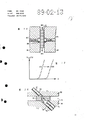
The horizontal sectional drawing of Figure 12 optical element the 8th embodiment (automatically controlled optical filter);
The light transmission powertrace of Figure 13 optical filter shown in Figure 12 is the function that wavelength and adjustable plate are adjusted;
Figure 14 is as optical element the 9th embodiment of automatically controlled smooth reversing switch.
The physical basis of optical element of the present invention is: as shown in Figure 1, if some is beyond electric field action to dielectric at first, so, the removable dielectric 1 in plate condenser 2 electric fields is inhaled into electric field (gradually becoming state of minimum energy).The relation of equal quantity formula that acts on constant charge Q on the power F of dielectric 1 and the condenser armature 2 is:
FQ= 1/2 · (ε-ε
o)/([ε
oa+(ε-ε
o)x]
2) · (d)/(h) Q
2
Wherein: X<a,
ε
oThe specific inductive capacity of environment space
The specific inductive capacity of ε dielectric 1
The h system is in the size perpendicular to page
All the other numerical value are introduced according to Fig. 1.
For constant voltage u, the power that acts on the dielectric 1 is:
F
u= 1/2 (ε-ε
o)·u
2· (h)/(d)
Wherein: x<a.
Optical element of the present invention based on above-mentioned principle can place diverse location with dielectric exactly by the electric field between the condenser armature 2.
Among Fig. 2 and first embodiment shown in Figure 3, optical element by spacing distance be the two parallel guide plates 10,11 of d and between them movably adjustable plate 12 form.The optical fiber 13,14 that has optical imaging system 19 inserts guide plate 10,11, and their free front surface is relative with movable adjustable plate 12. Guide plate 10,11 and adjustable plate 12 are made of dielectric material (for example glass plate).In the inboard of guide plate 10,11 parallel conduction strip shaped electric poles 15,16 is housed.Strip shaped electric poles can be made up of the transparent material of evaporation.It is not shown that single strip shaped electric poles 15,16 on each plate 10,11 all has the lead-in wire 18(control system that links to each other with control system), described control system is finished the voltage commutation between the single strip shaped electric poles 15,16.
The complete optical element of being made up of guide plate 10,11 and adjustable plate 12 places in the housing of sealing, is full of the liquid with appropriate index in the housing.
Apply a voltage to electrode 15,16 or their lead-in wire 18(tab character B respectively
iTo B
j) and cut off voltage (the tab character A of electrode 15,16 or their lead-in wire 18 respectively
iTo A
k), then electric field moves.Because above-mentioned basic functional principle, dielectric adjustable plate 12 is movable to new position, and can be moved to multiple different position according to number, distance and the size adjustment plate 12 of electrode 15,16.Owing to added the liquid with appropriate index, the frictional resistance that adjustable plate moves is minimum.
Voltage to be applied on the strip shaped electric poles 15,16 of two guide plates 10,11, must utilize the solid-state components that are loaded on one of guide plate 10,11 to realize required commutation with the manufacturing of glass-chip (Chip-on-glass) technology.The glass-chip technology belongs to a kind of ordinary skill for the LCD element.Then, only must be added on the solid-state components at one end forming the voltage of electric field and required control signal.
It is very little that adjustable plate 12 is moved on to reposition institute energy requirement, so power consumption is extremely low, and only the partition capacitance device needs charging.Adjustable plate 12 is a Millisecond in cycle positioning time of reposition, and the said time cycle is also depended on the inertia of adjustable plate 12.
In an embodiment, owing to moving only along a straight line coordinate of adjustable plate 12, so adjustable plate 12 must be by electric field itself or by a groove or by a retaining piece location.Because the location that need still can keep adjustable plate 12 when cutting off voltage, it is favourable therefore using the mechanical type location.
The origin position of adjustable plate must realize by electrical inertia or mechanical hook-up, for example, and by a mobile electric field in whole moving range, again by different mobile definite initial points that reach.
In second embodiment shown in Figure 4, optical element is made up of two guide plates 20,21 and adjustable plate 22, and adjustable plate 22 can move in the free guide space 27 in guide plate 21.Strip shaped electric poles 25,26 is sub-packed in the surface of guide plate 20,21, in the moving area of adjustable plate 22.Light imaging system 29 is loaded on the optical fiber 23,24.
Figure 5 shows that the 3rd embodiment.The outstanding advantage of this embodiment is that manufacturing is easy.Light imaging system 39 is loaded on respectively on the optical fiber 33,34.On dielectric guide plate 31, leave free guide space 37 for adjustable plate 32 mobile.Only the both sides evaporation of guide space 37 has two row's strip shaped electric poles 35,36 on guide plate 31.Also can load onto the solid-state components of usefulness glass-chip fabrication techniques to replace strip shaped electric poles 35,36 for guide plate 31 in the same way.Present embodiment realizes that preceding two embodiment of the required voltage ratio of the effect of same power want big.
Shown in Figure 6 is the 4th embodiment.This embodiment by flat guide plate 40, have for second guide plate 41 and two row's strip shaped electric poles 45,46 of the set guide space 47 of adjustable plate 42 and form.Optical fiber 43,44 inserts described guide plate 41 by light imaging system 49; Two row's strip shaped electric poles 45,46 place guide space 47 both sides on the guide plate 41.This enforcement can be used as automatically controlled optical attenuator component.
Fig. 7 and the 5th embodiment that Figure 8 shows that optical element.Different with the 4th embodiment, present embodiment is that the guide space 57 that adjustable plate 52 is provided with is positioned at guide plate 50,51 equably.Strip shaped electric poles 55,56 lays respectively at the outside of guide plate 50,51, in guide space 57 zone or adjustable plate 52 in guide space 57 in the mobile zone.Optical fiber 53,54 is terminated at optical imaging system 59, and the latter is inserted in the guide plate 50,51.
Figure 9 shows that the optical imaging system 59 between collimating optical fibre bundle 53 and another optical fiber 54 ends.
Below, the optical element of special use is described in more detail.Said optical element all is respectively applied for the location adjustable plate or forms electric field based on aforesaid basic functional principle and in the embodiment of Fig. 2~Fig. 7.Said optical element is said, just as any embodiment is possible in principle as just for example.
On optical transmission pathway, path attenuation must be adjusted to a setting, and keeps stable in a long time period.According to incoming level, a distant side signal is sent into transmitter, and regulate an optical attenuator element with a control signal, so that being lower than to give, the deviation of pad value and setting decides threshold value.Fig. 7 and the 5th embodiment as automatically controlled optical attenuator component shown in Figure 8 can finish above-mentioned functions.Wherein, adjustable plate 52, promptly the dielectric disc that can longitudinally change transmission moves between the leading face of optical fiber 53,54 based on aforesaid basic functional principle.According to the quantity of the position of adjustable plate 52, strip shaped electric poles 55,56 and continuously change transmit the number of times of adjustable plate 52, can with damping capacity between maximum and minimum value with the fixed intervals adjustment.The width of the degree of depth of guide space 57 and adjustable plate 52 adapts.
Figure 10 and shown in Figure 11 be respectively the citation form of optical element the 6th, seven embodiment.Optical element among the figure be can automatically controlled allotment ratio the optical power divider.In having the communication network of light transmission, a part of luminous power that coupling output is determined from transmission channel is a critical function.
In the citation form of the automatically controlled optical power divider shown in Figure 10,11, adjustable plate 62 or 72 is according to interference light filter segmentation difference, and according to the embodiment of aforementioned optical element be placed in respectively 60,70 and two output optical fibres 61,61 of input optical fibre ' or 71,71 ' between light path in.Utilize automatically controlled signal, adjustable plate is placed select location (strip shaped electric poles and guide plate are not shown in the drawings) between the guide plate that has strip shaped electric poles with the interval that differs in size.Thus, variable transmission or reflecting filter work respectively in beam path.Said light filter is served as by adjustable plate 62 or 72 respectively.Reflected optical power is coupled at half-mirror 68 places and outputs to output optical fibre 61 ' (Figure 10)
Optical element the 8th embodiment shown in Figure 12 is an automatically controlled light filter.In multichannel wavelength transmission system, light filter should place the end of light path in order to select to have the signal of specific wavelength.Can discern signal easily with tunable optical filter with different wave length.Adjustable plate 82 is light filters among the figure, and its position is by electric control.Light filter can move between guide plate 80,81, according to aforesaid principle of work, is to move between the workplace of input optical fibre 83 and output optical fibre 84.
Shown in Figure 13 is along be coupled when direction the moves fundamental curve of Output optical power of arrow A (curve A) or arrow B (curve B) for different wave length λ and adjustable plate 82.
At last, optical element the 9th embodiment shown in Figure 14 is an automatically controlled smooth reversing switch.In the network of light transmission is arranged,, start that to replace light path be rational when certain element or branching networks (for example, the localized network of band shape structure) when breaking down.For this reason, need make with the light reversing switch with the signal of input optical fibre 93 be coupled to two output optical fibres 94,94 ' in one.The known switch that is used for this purpose is to utilize the direct mechanical of optical fiber to move or piezoelectricity control is moved.By all constituting by dielectric material at two guide plates 90, each guide plate of 91() between configuration adjustment plate 92, when the refractive index n 2 of adjustable plate 92 materials hank with the refractive index n 1 of other material on every side obviously not simultaneously, just can constitute a simple reversing switch that has transparent dielectric adjustable plate 92.In addition, also can in optical switching network, form optical matrix.
If the adjustable plate 52 of the 5th embodiment shown in Fig. 7 and Fig. 8 is changed to the nontransparent adjustable plate that moves in having the liquid of appropriate index, then also can constitute the optical switch identical with the 5th example structure.Those inefficient optical switches can be used and replace to this (even have large-diameter fibre-optical core) optical switch in having the display system of fiber optical waveguide.Big minispread optical switch according to symbol or video is useful.
Claims (11)
1, a kind of optical element that is used for two or multifiber, attenuating elements for example, light filter, power divider or like, at least constitute by two optical fiber supporting members and the regulating part that can between two supporting members, move, it is characterized in that, supporting member becomes guide plate, regulating part becomes the adjustable plate that dielectric material is done, adjustable plate can move in the guide space between guide plate, have at least a guide plate to have the electrode surface that forms at least one dielectric field, described electrode surface links to each other with an adjustable voltage source of supply.
2, optical element as claimed in claim 1 is characterized in that, dielectric material is a glass.
3, optical element as claimed in claim 1 or 2 is characterized in that, electrode surface is made of the strip shaped electric poles of each interval.
4, optical element as claimed in claim 3 is characterized in that, strip shaped electric poles is made of the transparent material of conduction.
5, optical element as claimed in claim 3 is characterized in that, strip shaped electric poles is that evaporation is to the guide plate inside surface.
6, optical element as claimed in claim 1 or 2 is characterized in that, the guide space of adjustable plate is arranged in a groove of a guide plate.
7, optical element as claimed in claim 3 is characterized in that, strip shaped electric poles is arranged on the surface of the guide plate of determining guide space with two parallel rows.
8, optical element as claimed in claim 3 is characterized in that, strip shaped electric poles with two parallel rankings in a guide plate (31; 41) guide space (37; 47) on Pang Bian the surface.
9, optical element as claimed in claim 1 or 2 is characterized in that, determines the degree of depth of guide space with the thickness of adjustable plate.
10, optical element as claimed in claim 1 or 2 is characterized in that, determines the degree of depth of guide space (47) with the width of adjustable plate (42).
11, optical element as claimed in claim 3 is characterized in that, guide space (57) is by two guide plates (50,51) lip-deep two grooves constitute, and strip shaped electric poles (55,56) places guide plate (50,51) outside is in the moving area of adjustable plate (52).
Applications Claiming Priority (2)
| Application Number | Priority Date | Filing Date | Title |
|---|---|---|---|
| DE3804822A DE3804822C1 (en) | 1988-02-12 | 1988-02-12 | |
| DEP38048221 | 1988-02-12 |
Publications (2)
| Publication Number | Publication Date |
|---|---|
| CN1036841A CN1036841A (en) | 1989-11-01 |
| CN1011739B true CN1011739B (en) | 1991-02-20 |
Family
ID=6347531
Family Applications (1)
| Application Number | Title | Priority Date | Filing Date |
|---|---|---|---|
| CN89101841A Expired CN1011739B (en) | 1988-02-12 | 1989-02-11 | Optical element for optical fibre transmission system |
Country Status (25)
| Country | Link |
|---|---|
| US (1) | US4919503A (en) |
| EP (1) | EP0328738B1 (en) |
| JP (1) | JPH024208A (en) |
| KR (1) | KR920005876B1 (en) |
| CN (1) | CN1011739B (en) |
| AT (1) | ATE61672T1 (en) |
| AU (1) | AU604995B2 (en) |
| CA (1) | CA1311822C (en) |
| DD (1) | DD283465A5 (en) |
| DE (2) | DE3804822C1 (en) |
| DK (1) | DK63789A (en) |
| ES (1) | ES2021128B3 (en) |
| FI (1) | FI89310C (en) |
| GR (1) | GR3001599T3 (en) |
| HK (1) | HK106691A (en) |
| IE (1) | IE60842B1 (en) |
| IL (1) | IL88221A (en) |
| MX (1) | MX170460B (en) |
| NO (1) | NO173036C (en) |
| NZ (1) | NZ227942A (en) |
| PT (1) | PT89685B (en) |
| RU (1) | RU1828550C (en) |
| SG (1) | SG64891G (en) |
| TR (1) | TR24475A (en) |
| ZA (1) | ZA891050B (en) |
Families Citing this family (13)
| Publication number | Priority date | Publication date | Assignee | Title |
|---|---|---|---|---|
| JPS5953426A (en) * | 1982-09-21 | 1984-03-28 | Wakunaga Seiyaku Kk | Remedy for psychogenic asynodia |
| US4945229A (en) * | 1988-12-29 | 1990-07-31 | Thomas & Betts Corporation | Fiber optic receiver and transceiver |
| GB2295687A (en) * | 1994-12-01 | 1996-06-05 | Ford Motor Co | Manually operable optical switch with encoded shutter |
| DE19520167B4 (en) * | 1995-06-01 | 2006-08-24 | Sick Ag | Method and device for opto-electronic distance measurement according to the transit time method |
| AU758244B2 (en) * | 1998-12-09 | 2003-03-20 | American Sterilizer Company | Fiber optic ceiling supported surgical task light system with optical commutator and manual zoom lens |
| WO2000039626A1 (en) * | 1998-12-31 | 2000-07-06 | Optical Coating Laboratory, Inc. | Wavelength selective optical switch |
| US6430322B1 (en) * | 1999-11-23 | 2002-08-06 | L3 Optics, Inc. | Optical phase shifter having an integrated planar optical waveguide and phase shifter element |
| US6587608B2 (en) * | 2000-11-14 | 2003-07-01 | Chameleon Optics, Inc. | Reconfigurable, all optical add/drop nodes using non-interrupting switching apparatus and methods |
| WO2002086596A1 (en) | 2001-04-20 | 2002-10-31 | Cormack Robert H | Polarization insensitive tunable optical filters |
| US6807356B2 (en) * | 2001-12-10 | 2004-10-19 | Jds Uniphase Corporation | Fiber-coupled optical attenuator |
| JP2003241120A (en) | 2002-02-22 | 2003-08-27 | Japan Aviation Electronics Industry Ltd | Optical device |
| KR20060035810A (en) | 2002-02-26 | 2006-04-26 | 유니-픽셀 디스플레이스, 인코포레이티드 | Airgap autogenesis mechanism |
| US7015458B2 (en) * | 2002-10-10 | 2006-03-21 | Emerging Manufacturing Technology, Inc. | High density fiber optic output interface and system |
Family Cites Families (10)
| Publication number | Priority date | Publication date | Assignee | Title |
|---|---|---|---|---|
| US4223217A (en) * | 1977-05-12 | 1980-09-16 | Eaton Corporation | Fiber optic electric switch |
| JPS5526558A (en) * | 1978-08-15 | 1980-02-26 | Nippon Telegr & Teleph Corp <Ntt> | Photo switch |
| DE2936463A1 (en) * | 1979-09-10 | 1981-03-19 | Siemens AG, 1000 Berlin und 8000 München | DEVICE FOR GENERATING MOVING LIGHT BEAMS |
| DE3138968A1 (en) * | 1981-09-30 | 1983-04-14 | Siemens AG, 1000 Berlin und 8000 München | OPTICAL CONTROL DEVICE FOR CONTROLLING THE RADIATION GUIDED IN AN OPTICAL WAVE GUIDE, IN PARTICULAR OPTICAL SWITCHES |
| DE3206919A1 (en) * | 1982-02-26 | 1983-09-15 | Philips Patentverwaltung Gmbh, 2000 Hamburg | DEVICE FOR OPTICALLY DISCONNECTING AND CONNECTING LIGHT GUIDES |
| DE3223898C2 (en) * | 1982-06-26 | 1984-04-19 | Standard Elektrik Lorenz Ag, 7000 Stuttgart | Adjustable optical attenuator |
| CA1258786A (en) * | 1985-04-11 | 1989-08-29 | Omur M. Sezerman | Tilt adjustable optical fibre connectors |
| JPS61275717A (en) * | 1985-05-31 | 1986-12-05 | Ricoh Co Ltd | Optical shutter device |
| JPS61285419A (en) * | 1985-06-13 | 1986-12-16 | Seiko Epson Corp | Optical writing printer |
| US4753507A (en) * | 1986-01-07 | 1988-06-28 | Litton Systems, Inc. | Piezoelectric loading housing and method |
-
1988
- 1988-02-12 DE DE3804822A patent/DE3804822C1/de not_active Expired
- 1988-10-20 EP EP88117463A patent/EP0328738B1/en not_active Expired - Lifetime
- 1988-10-20 ES ES88117463T patent/ES2021128B3/en not_active Expired - Lifetime
- 1988-10-20 DE DE8888117463T patent/DE3862024D1/en not_active Expired - Fee Related
- 1988-10-20 AT AT88117463T patent/ATE61672T1/en not_active IP Right Cessation
- 1988-10-28 IL IL88221A patent/IL88221A/en not_active IP Right Cessation
- 1988-11-23 CA CA000583925A patent/CA1311822C/en not_active Expired - Lifetime
- 1988-11-30 AU AU26428/88A patent/AU604995B2/en not_active Ceased
- 1988-12-09 JP JP63311823A patent/JPH024208A/en active Pending
- 1988-12-27 US US07/291,536 patent/US4919503A/en not_active Expired - Fee Related
-
1989
- 1989-02-08 IE IE40889A patent/IE60842B1/en not_active IP Right Cessation
- 1989-02-09 DD DD89325657A patent/DD283465A5/en not_active IP Right Cessation
- 1989-02-09 NO NO890550A patent/NO173036C/en unknown
- 1989-02-10 DK DK063789A patent/DK63789A/en not_active Application Discontinuation
- 1989-02-10 PT PT89685A patent/PT89685B/en not_active IP Right Cessation
- 1989-02-10 NZ NZ227942A patent/NZ227942A/en unknown
- 1989-02-10 TR TR89/0149A patent/TR24475A/en unknown
- 1989-02-10 RU SU894613536A patent/RU1828550C/en active
- 1989-02-10 MX MX014880A patent/MX170460B/en unknown
- 1989-02-10 FI FI890667A patent/FI89310C/en not_active IP Right Cessation
- 1989-02-10 ZA ZA891050A patent/ZA891050B/en unknown
- 1989-02-11 CN CN89101841A patent/CN1011739B/en not_active Expired
- 1989-02-13 KR KR1019890001624A patent/KR920005876B1/en not_active IP Right Cessation
-
1991
- 1991-03-14 GR GR91400198T patent/GR3001599T3/en unknown
- 1991-08-12 SG SG64891A patent/SG64891G/en unknown
- 1991-12-23 HK HK1066/91A patent/HK106691A/en unknown
Also Published As
Similar Documents
| Publication | Publication Date | Title |
|---|---|---|
| CN1011739B (en) | Optical element for optical fibre transmission system | |
| US3931518A (en) | Optical fiber power taps employing mode coupling means | |
| US4720171A (en) | Liquid crystal optical switching device having reduced crosstalk | |
| BR9803400A (en) | Low attenuation optical waveguide. | |
| EP0488708B1 (en) | Optical switching device | |
| AU543708B2 (en) | A lens having a high refractive index with a low dispersion | |
| US4722583A (en) | Modulators | |
| CA2149267A1 (en) | Electric field sensor | |
| GB2031609A (en) | Coupling arrangements for optical fibres | |
| CN1266536C (en) | Method and apparatus for switching optical signals with photon band gap device | |
| CN115808744A (en) | High-consistency optical fiber optical switch | |
| US4720174A (en) | Liquid crystal optical switching device with integrally attached optical fibers | |
| KR100501195B1 (en) | MEMS Variable Optical Attenuator Having A Moving Optical Waveguide and Method of Driving The Moving Optical Waveguide | |
| CN1555146A (en) | Integrated light power adjustable optical wave division duplexer | |
| CN218782434U (en) | High-consistency optical fiber optical switch | |
| JPS6375726A (en) | Optical attenuator | |
| US20020176685A1 (en) | Variable optical attenuator | |
| CN209590484U (en) | A kind of adjustable light wave-filter based on orthogonal liquid crystal | |
| GB2327773A (en) | Planar optical segmented waveguide for attenuation | |
| US20020009280A1 (en) | Variable optical attenuator | |
| JPS56102806A (en) | Light distributing circuit for optical fiber communication | |
| CN110174781B (en) | Micro-ring electro-optical switch array device with net structure | |
| CA1245087A (en) | Light by-passing device | |
| CN100368840C (en) | Fibre-optical switch | |
| US6633721B2 (en) | Variable optical attenuator |
Legal Events
| Date | Code | Title | Description |
|---|---|---|---|
| C06 | Publication | ||
| PB01 | Publication | ||
| C10 | Entry into substantive examination | ||
| SE01 | Entry into force of request for substantive examination | ||
| C13 | Decision | ||
| GR02 | Examined patent application | ||
| C14 | Grant of patent or utility model | ||
| GR01 | Patent grant | ||
| C19 | Lapse of patent right due to non-payment of the annual fee | ||
| CF01 | Termination of patent right due to non-payment of annual fee |