CN101162577B - Image processing apparatus, image transmission apparatus, image reception apparatus, and image processing method - Google Patents
Image processing apparatus, image transmission apparatus, image reception apparatus, and image processing method Download PDFInfo
- Publication number
- CN101162577B CN101162577B CN2007101812158A CN200710181215A CN101162577B CN 101162577 B CN101162577 B CN 101162577B CN 2007101812158 A CN2007101812158 A CN 2007101812158A CN 200710181215 A CN200710181215 A CN 200710181215A CN 101162577 B CN101162577 B CN 101162577B
- Authority
- CN
- China
- Prior art keywords
- image
- image processing
- bit
- raster
- raster image
- Prior art date
- Legal status (The legal status is an assumption and is not a legal conclusion. Google has not performed a legal analysis and makes no representation as to the accuracy of the status listed.)
- Expired - Fee Related
Links
Images


Classifications
-
- G—PHYSICS
- G09—EDUCATION; CRYPTOGRAPHY; DISPLAY; ADVERTISING; SEALS
- G09G—ARRANGEMENTS OR CIRCUITS FOR CONTROL OF INDICATING DEVICES USING STATIC MEANS TO PRESENT VARIABLE INFORMATION
- G09G5/00—Control arrangements or circuits for visual indicators common to cathode-ray tube indicators and other visual indicators
- G09G5/02—Control arrangements or circuits for visual indicators common to cathode-ray tube indicators and other visual indicators characterised by the way in which colour is displayed
-
- G—PHYSICS
- G09—EDUCATION; CRYPTOGRAPHY; DISPLAY; ADVERTISING; SEALS
- G09G—ARRANGEMENTS OR CIRCUITS FOR CONTROL OF INDICATING DEVICES USING STATIC MEANS TO PRESENT VARIABLE INFORMATION
- G09G3/00—Control arrangements or circuits, of interest only in connection with visual indicators other than cathode-ray tubes
- G09G3/20—Control arrangements or circuits, of interest only in connection with visual indicators other than cathode-ray tubes for presentation of an assembly of a number of characters, e.g. a page, by composing the assembly by combination of individual elements arranged in a matrix no fixed position being assigned to or needed to be assigned to the individual characters or partial characters
- G09G3/34—Control arrangements or circuits, of interest only in connection with visual indicators other than cathode-ray tubes for presentation of an assembly of a number of characters, e.g. a page, by composing the assembly by combination of individual elements arranged in a matrix no fixed position being assigned to or needed to be assigned to the individual characters or partial characters by control of light from an independent source
- G09G3/36—Control arrangements or circuits, of interest only in connection with visual indicators other than cathode-ray tubes for presentation of an assembly of a number of characters, e.g. a page, by composing the assembly by combination of individual elements arranged in a matrix no fixed position being assigned to or needed to be assigned to the individual characters or partial characters by control of light from an independent source using liquid crystals
- G09G3/3611—Control of matrices with row and column drivers
- G09G3/3685—Details of drivers for data electrodes
- G09G3/3688—Details of drivers for data electrodes suitable for active matrices only
-
- H—ELECTRICITY
- H04—ELECTRIC COMMUNICATION TECHNIQUE
- H04N—PICTORIAL COMMUNICATION, e.g. TELEVISION
- H04N19/00—Methods or arrangements for coding, decoding, compressing or decompressing digital video signals
- H04N19/10—Methods or arrangements for coding, decoding, compressing or decompressing digital video signals using adaptive coding
- H04N19/169—Methods or arrangements for coding, decoding, compressing or decompressing digital video signals using adaptive coding characterised by the coding unit, i.e. the structural portion or semantic portion of the video signal being the object or the subject of the adaptive coding
- H04N19/184—Methods or arrangements for coding, decoding, compressing or decompressing digital video signals using adaptive coding characterised by the coding unit, i.e. the structural portion or semantic portion of the video signal being the object or the subject of the adaptive coding the unit being bits, e.g. of the compressed video stream
-
- H—ELECTRICITY
- H04—ELECTRIC COMMUNICATION TECHNIQUE
- H04N—PICTORIAL COMMUNICATION, e.g. TELEVISION
- H04N19/00—Methods or arrangements for coding, decoding, compressing or decompressing digital video signals
- H04N19/42—Methods or arrangements for coding, decoding, compressing or decompressing digital video signals characterised by implementation details or hardware specially adapted for video compression or decompression, e.g. dedicated software implementation
- H04N19/423—Methods or arrangements for coding, decoding, compressing or decompressing digital video signals characterised by implementation details or hardware specially adapted for video compression or decompression, e.g. dedicated software implementation characterised by memory arrangements
- H04N19/426—Methods or arrangements for coding, decoding, compressing or decompressing digital video signals characterised by implementation details or hardware specially adapted for video compression or decompression, e.g. dedicated software implementation characterised by memory arrangements using memory downsizing methods
-
- H—ELECTRICITY
- H04—ELECTRIC COMMUNICATION TECHNIQUE
- H04N—PICTORIAL COMMUNICATION, e.g. TELEVISION
- H04N19/00—Methods or arrangements for coding, decoding, compressing or decompressing digital video signals
- H04N19/50—Methods or arrangements for coding, decoding, compressing or decompressing digital video signals using predictive coding
- H04N19/59—Methods or arrangements for coding, decoding, compressing or decompressing digital video signals using predictive coding involving spatial sub-sampling or interpolation, e.g. alteration of picture size or resolution
-
- G—PHYSICS
- G09—EDUCATION; CRYPTOGRAPHY; DISPLAY; ADVERTISING; SEALS
- G09G—ARRANGEMENTS OR CIRCUITS FOR CONTROL OF INDICATING DEVICES USING STATIC MEANS TO PRESENT VARIABLE INFORMATION
- G09G2300/00—Aspects of the constitution of display devices
- G09G2300/04—Structural and physical details of display devices
- G09G2300/0404—Matrix technologies
- G09G2300/0408—Integration of the drivers onto the display substrate
-
- G—PHYSICS
- G09—EDUCATION; CRYPTOGRAPHY; DISPLAY; ADVERTISING; SEALS
- G09G—ARRANGEMENTS OR CIRCUITS FOR CONTROL OF INDICATING DEVICES USING STATIC MEANS TO PRESENT VARIABLE INFORMATION
- G09G2310/00—Command of the display device
- G09G2310/02—Addressing, scanning or driving the display screen or processing steps related thereto
- G09G2310/0264—Details of driving circuits
- G09G2310/027—Details of drivers for data electrodes, the drivers handling digital grey scale data, e.g. use of D/A converters
-
- G—PHYSICS
- G09—EDUCATION; CRYPTOGRAPHY; DISPLAY; ADVERTISING; SEALS
- G09G—ARRANGEMENTS OR CIRCUITS FOR CONTROL OF INDICATING DEVICES USING STATIC MEANS TO PRESENT VARIABLE INFORMATION
- G09G2330/00—Aspects of power supply; Aspects of display protection and defect management
- G09G2330/02—Details of power systems and of start or stop of display operation
- G09G2330/021—Power management, e.g. power saving
-
- G—PHYSICS
- G09—EDUCATION; CRYPTOGRAPHY; DISPLAY; ADVERTISING; SEALS
- G09G—ARRANGEMENTS OR CIRCUITS FOR CONTROL OF INDICATING DEVICES USING STATIC MEANS TO PRESENT VARIABLE INFORMATION
- G09G2340/00—Aspects of display data processing
- G09G2340/02—Handling of images in compressed format, e.g. JPEG, MPEG
-
- G—PHYSICS
- G09—EDUCATION; CRYPTOGRAPHY; DISPLAY; ADVERTISING; SEALS
- G09G—ARRANGEMENTS OR CIRCUITS FOR CONTROL OF INDICATING DEVICES USING STATIC MEANS TO PRESENT VARIABLE INFORMATION
- G09G2340/00—Aspects of display data processing
- G09G2340/04—Changes in size, position or resolution of an image
- G09G2340/0407—Resolution change, inclusive of the use of different resolutions for different screen areas
- G09G2340/0428—Gradation resolution change
-
- G—PHYSICS
- G09—EDUCATION; CRYPTOGRAPHY; DISPLAY; ADVERTISING; SEALS
- G09G—ARRANGEMENTS OR CIRCUITS FOR CONTROL OF INDICATING DEVICES USING STATIC MEANS TO PRESENT VARIABLE INFORMATION
- G09G2360/00—Aspects of the architecture of display systems
- G09G2360/18—Use of a frame buffer in a display terminal, inclusive of the display panel
-
- G—PHYSICS
- G09—EDUCATION; CRYPTOGRAPHY; DISPLAY; ADVERTISING; SEALS
- G09G—ARRANGEMENTS OR CIRCUITS FOR CONTROL OF INDICATING DEVICES USING STATIC MEANS TO PRESENT VARIABLE INFORMATION
- G09G3/00—Control arrangements or circuits, of interest only in connection with visual indicators other than cathode-ray tubes
- G09G3/20—Control arrangements or circuits, of interest only in connection with visual indicators other than cathode-ray tubes for presentation of an assembly of a number of characters, e.g. a page, by composing the assembly by combination of individual elements arranged in a matrix no fixed position being assigned to or needed to be assigned to the individual characters or partial characters
- G09G3/2007—Display of intermediate tones
- G09G3/2044—Display of intermediate tones using dithering
- G09G3/2051—Display of intermediate tones using dithering with use of a spatial dither pattern
-
- G—PHYSICS
- G09—EDUCATION; CRYPTOGRAPHY; DISPLAY; ADVERTISING; SEALS
- G09G—ARRANGEMENTS OR CIRCUITS FOR CONTROL OF INDICATING DEVICES USING STATIC MEANS TO PRESENT VARIABLE INFORMATION
- G09G5/00—Control arrangements or circuits for visual indicators common to cathode-ray tube indicators and other visual indicators
- G09G5/003—Details of a display terminal, the details relating to the control arrangement of the display terminal and to the interfaces thereto
- G09G5/006—Details of the interface to the display terminal
Abstract
The invention provides an image processing apparatus which reduces the bit plane quantity of the raster image used as the primary image, and increases the reduced bit plane quantity of the raster image to equal to or less than the bit plane quantity of the primary image. The invention comprises a first image processing device for executing a multi-valued dither processing through a two-dimensional dither matrix when reducing the bit plane quantity of the raster image; a second image processing device for executing a frame frequency control processing so as to change the tone periodically based on the two-dimensional dither matrix used by the first image processing device when increasing the reduced bit plane quantity of the raster image.
Description
The application is dividing an application of application for a patent for invention 02818085.2.
Technical field
The present invention relates to image processing apparatus, image transfer apparatus and image processing method, and more particularly, relate to for the display of the storer by having the storage raster image and improve raster image is sent to the efficient of display from computing machine, in image is processed, realize image processing apparatus, image transfer apparatus and the image processing method of high quality graphic.
Background technology
At present, for image is sent to display from computing machine, adopt according to every frame rate, transmit the method for raster image.This method requires a large amount of data that transmit, and therefore, when just showing rest image, is absorbed in and transmits waste.
As for reducing the measure that transmits data volume, compression of images can be become the file layout such as JPEG and GIF, then transmit.Yet, be necessary to have execution and be used for according to every frame, the processor of the high speed operation of compression and decompressed image, thus cause cost to increase.
On the other hand, as the measure that transmits waste when showing rest image, can provide built-in frame memory with the storer that acts on the storage raster image for display, when just showing rest image with box lunch, suspension data transmits.This measure is effective especially concerning mobile information apparatus etc., because it can also reduce electrical power consumed.
The display in being installed in mobile information apparatus, it is very important to reduce electrical power consumed and die size.Therefore, expectation should show the image that is stored in the storer when demonstration during rest image, and take capacity or the size of the storer of most of die size should be very little.By storing the image on just now in the described storer, can reduce the electrical power consumed of data in transmitting.In addition, reducing storage capacity requirement means and can reduce die size.
For reducing memory span, can compressing image data.Yet, according to the method for compressing image data that utilizes such as the form of JPEG and GIF, require to have the image processor for decompressing image, this overslaugh reduce the effect of electrical power consumed and die size.
Other method relates to the bit plane quantity that reduces raster image.Here, bit plane quantity refers to that expression is by 2
nThe quantity n of the tone of the digital picture that has quantized or the data bit of gray level.Example for reducing the method for bit plane quantity comprises many-valued shake (multivalued dither) method and fixed threshold method.The particulars of relevant these methods were described among the pp41-51 in " The New ImageElectron Handbook " (Tokyo, Corona Publishing Co.Ltd., 1993).Many-valued dither method and fixed threshold method be different from utilize form JPEG and GIF such as the method for compressing image data part be that compressed image does not need to decompress.
Fig. 1 is the block diagram that schematically shows the structure of traditional image processing apparatus.With reference to figure 1, to provide by traditional many-valued dither method, the description of the example of bit plane Compressed grating image wherein transmits the rgb light grid image that each color component has 6 from computing machine, and image display part shows each color component, has 6 image.
At first, 6 low level of each color component of raster image 1 or minimum effective 2 are sent to comparer 12.Based on orderly shake, threshold generator 11 produces dither matrixs, and will output to comparer 12 according to well-determined 2 place values of the pixel (X-Y coordinate figure) of input picture.
2 of low orders that comparer 12 will send from raster image 1 compare with 2 place values from threshold generator 11.When the value that receives from threshold generator 11 during greater than 2 of low orders, comparer 12 outputs to selector switch 13 with " 1 ".Otherwise comparer 12 outputs to selector switch 13 with " 0 ".
Based on the output valve from comparer 12, selector switch 13 is directly with the high-order of raster image 1 or the highest effective 4 or output to storer 2 by the value that deducts 1 rear acquisition.To being stored in the every color component in the storer 2, have 4 image, by position optional feature 14, the value of 2 of 4 high-orders is appended on 4 place values of inputting as low-order bit, and image is outputed to image display part 3 as 6 bit images.
By this structure, by many-valued dither method, reduce number of bit-planes, and show that each color component has 6 pseudo-image.
In addition, Japanese patent application publication No. No.HEI2-8493 (B) (the first prior art) discloses digital signal processing device, its executive level compression (level compression) digital input signals is sent to this compressed signal so that transmission signal and rank decompress, comprise be respectively applied to detect the maximal value of digital signal, based on maximal value, after being increased to jitter value on the digital signal, a plurality of circuit that executive level compression, executive level decompress and deduct jitter value from digital signal.
By this structure, can obtain the output into the less difference in the digital audio and video signals of one-dimensional signal.
Summary of the invention
According to traditional many-valued dither method and fixed threshold method, yet, reduce bit plane quantity and cause pseudo-profile and pseudo-color, and produce granular image.Therefore, reduce picture quality.
Exist and be called overlapping demonstration style.This is for the technology that different images such as " text " is superimposed upon on the displaying screen images.In the situation of overlapping demonstration, need a plurality of images (for example image or figure and text) as input picture, increased the quantity of input image data, therefore, be difficult to be stored in input picture in the storer and the transfer bus through having the highway width restriction transmits them.
In addition, on the display of for example portable terminal, its demonstration has the figure of low ultimate resolution, when the very large for example map of shown image, is necessary the image that rolls.This roll display is to seem shirtsleeve operation.Yet, display-memory is rewritten repeatedly, therefore, increased electrical power consumed.
On the other hand, shown in Fig. 2 (a), when when display device etc. shows image, input signal is input to along in each pixel of main scanning line and time sweep trace, and with respect to many lines, repeat this operation in order to picture signal can be input in all pixels.
Suppose that the first prior art is applicable to image and shows here.Incidentally, in this example, the shake cycle is set to 4.
Shown in Fig. 2 (b), when the pixel quantity in the main scanning direction of display is 4n+1, shake appears periodically in main scanning direction and time direction of scanning, and therefore, the compression and decompression image causes less deterioration of image quality.When the pixel quantity in the main scanning direction of display is the situation of 4n+2 or 4n+3, also be like this.That is, the pixel quantity in the main scanning direction of display is not included as the shake cycle in the situation of the factor, and the compression and decompression image causes less deterioration of image quality.
Yet, when the pixel quantity in the main scanning direction of display is 4n, in other words, when the pixel in the main scanning direction of display is included as the factor with the shake cycle, in inferior direction of scanning, do not observe shake periodically, and in main scanning direction, occur, shown in Fig. 2 (c).Therefore, aggravated because the deterioration of image quality that the compression and decompression image causes.
In the situation of the dithering process that is used for raster image, owing to along with the shake cycle diminishes, can obtain the high frequency minimal noise, might reduce deterioration of image quality.Yet the pixel quantity in the main scanning direction of display comprises that normally " 2 " to " 6 " are as the quantity of the factor (for example 480,720,840 etc.).Therefore, when the first prior art being applied to the image demonstration, in inferior direction of scanning, not observing shake periodically, and in main scanning direction, occur, shown in Fig. 2 (c).Therefore, by the compression and decompression image, make deterioration of image quality.
In the time will shaking quality settings for larger value in order to not be the factor of quantity of the pixel in the main scanning direction that shows, can not obtain the high frequency minimal noise of the required purpose of dithering process.Therefore, by the compression and decompression image, make deterioration of image quality.
In addition, if directly use the first prior art, require to have maximum value detecting circuit in compression end, be used to specify the position of the digital signal that forms by a plurality of, will increase jitter value, and as required, transmit the signal that expression has the maximum bit position of the peaked utilization of digital signal.In addition, in situation about compression digital signal being stored in storer etc., must utilize the signal of the highest bit position to be stored in the storer together with this digital signal expression.
The structure that is used for this processing of execution needs complicated circuit, and this has increased electrical power consumed and die size.Therefore, this structure is not suitable for image processing apparatus, such as display.
In addition, the first prior art does not have instruction or suggestion with respect to the maximal value of digital signal and the disposal route of minimum value.Therefore, in the image processing apparatus that usually provides the demonstration of " white " or maximal value and " black " or minimum value to show (for example, text output, geometry show etc.), make deterioration of image quality.This is because when " black " and " white " shows, usually produces granular image.
As described, when directly the first prior art being applied to the image processing, the compression and decompression image causes very little deterioration of image quality.
Therefore, when the first prior art being applied to the image demonstration, be necessary to adopt the structure of the dither matrix that is suitable for raster image or 2D signal.In addition, owing to according to image type (text display or natural image show), make the tone variation of pixel, expectation is carried out the image that is suitable for raster image and is processed.
In addition, when the display presentation video, always do not compress all images.For example, in the situation of Cine mode, carry out the compression and decompression image with respect to every frame, thereby increased electrical power consumed and operation amount.For this reason, do not expect the compression and decompression image.
Therefore, the purpose of this invention is to provide image processing apparatus, image transfer apparatus, image received device and image processing method, even be used for reducing memory span, also image can be shown the same with the master grating image well, allow to reduce transmittability and be used for transmitting raster image data storage capacity and suppress simultaneously deterioration of image quality.Another object of the present invention provides image processing apparatus, image transfer apparatus, image received device and method for compressing image, be used for when increasing the efficient that image transmits and storer utilizes, carries out image processing, thus allow to reduce electrical power consumed and operation amount.
According to a first aspect of the invention, for achieving the above object, provide image processing apparatus, comprise the first image processing apparatus, be used for reducing the number of bit-planes as the raster image of original image, and the second image processing apparatus, for increasing number of bit-planes.
Image processing apparatus according to a first aspect of the invention is one that selects from following image processing apparatus 1-1 to 1-3.
1-1: a kind of image processing apparatus, minimizing is as the number of bit-planes of the raster image of original image, and after this, make the number of bit-planes of the minimizing of described raster image be increased to the quantity of the number of bit-planes that is equal to or less than described original image, comprise: the first image processing apparatus, be used for when reducing the number of bit-planes of described raster image, by using two-dimentional dither matrix, carrying out many-valued dithering process; And second image processing apparatus, when being used for the number of bit-planes when the minimizing of the described raster image of increase, based on two-dimentional dither matrix and the described gray level that has reduced the raster image of its number of bit-planes used by described the first image processing apparatus, execute bit additional treatments.
1-2: a kind of image processing apparatus, minimizing is as the number of bit-planes of the raster image of original image, and after this, make the number of bit-planes of the minimizing of described raster image be increased to the quantity of the number of bit-planes that is equal to or less than described original image, comprise: the first image processing apparatus, be used for when reducing the number of bit-planes of described raster image, by using two-dimentional dither matrix, carrying out many-valued dithering process; And second image processing apparatus, when being used for the number of bit-planes when the minimizing that increases described raster image, based on the two-dimentional dither matrix that is used by described the first image processing apparatus, carry out frame frequency control processing so that the periodic variation tone.
1-3: a kind of image processing apparatus, minimizing is as the number of bit-planes of the raster image of original image, and after this, make the number of bit-planes of the minimizing of described raster image be increased to the quantity of the number of bit-planes that is equal to or less than described original image, comprise: the first image processing apparatus, be used for when reducing the number of bit-planes of described raster image, by using two-dimentional dither matrix, carrying out many-valued dithering process; And second image processing apparatus, when being used for the number of bit-planes when the minimizing of the described raster image of increase, based on the two-dimentional dither matrix that is used by described the first image processing apparatus, the execute bit additional treatments, and increase off-set value so that the difference between the mean value of all jitter values of the signal value of described original image and the described raster image that has increased its number of bit-planes will be minimum value.
Best, in any structure according to a first aspect of the invention, through having the transfer bus less than the highway width of the number of bit-planes of described original image, transmit the described raster image that has reduced its number of bit-planes.In addition, expect that this image processing apparatus further comprises storer, be used for storage has reduced the raster image of its number of bit-planes by this first image processing apparatus data, and this second image processing apparatus is read the data that are stored in this raster image in this storer in order to increase its number of bit-planes.In addition, this second image processing apparatus is preferably formed on the substrate, forms the driving circuit of this display at this substrate.Further, this first image processing apparatus is preferably formed on the substrate, forms the driving circuit of this display at this substrate.
According to a first aspect of the invention, the first image processing apparatus reduces the number of bit-planes as the first raster image of original image, and after this, the second image processing apparatus increases the number of bit-planes that reduces.Therefore, can pass through less logic element, compression and decompression are sent to the bitmap images of display, thereby allow to reduce memory capacity and transmission capacity.
In addition, in a first aspect of the present invention, when reducing the number of bit-planes of raster image, by using two-dimentional dither matrix, carry out many-valued dithering process, and when the number of bit-planes of the minimizing that increases raster image, based on the two-dimentional dither matrix that is used for many-valued dithering process, execute bit additional treatments.Therefore, compare with many-valued dither method, the image and the difference between original image that have stood an additional treatments are less.Thereby, can be suppressed at granular sensation and the pseudo-color of seeing in the situation of two big-differences between image, and realize that high quality graphic shows.
Incidentally, be formed in the situation of the display on the substrate (for example glass substrate) a first aspect of the present invention being applied to its driving circuit, can form image processing apparatus at substrate by identical method.Therefore, the application of the image processing apparatus of the third aspect allows to reduce memory block and electrical power consumed.
According to a second aspect of the invention, for achieving the above object, provide image processing apparatus, the fair raster image that can determine directly to export as original image is still exported and is reduced/increase its number of bit-planes or the image crossed of compression/de-compression.
Image processing apparatus according to a third aspect of the invention we is one that selects from following image processing apparatus 2-1 to 2-3.
2-1: a kind of image processing apparatus, minimizing is as the number of bit-planes of the first raster image of original image, and after this, the quantity that the number of bit-planes of the minimizing by making described raster image is increased to the number of bit-planes that is equal to or less than described original image produces the second raster image, comprise: the first image processing apparatus, be used for when reducing the number of bit-planes of described the first raster image, by using two-dimentional dither matrix, carrying out many-valued dithering process; The second image processing apparatus is when being used for the number of bit-planes when the minimizing that increases described raster image, based on the two-dimentional dither matrix by described the first image processing apparatus use, execute bit additional treatments; And selecting arrangement, be used for selecting described the first raster image or described the second raster image, and export selected image, wherein: by described selecting arrangement, when described original image is rest image, select described the second raster image, and when described original image is moving image, select described the first raster image.
2-2: a kind of image processing apparatus, minimizing is as the number of bit-planes of the first raster image of original image, and after this, the quantity that the number of bit-planes of the minimizing by making described raster image is increased to the number of bit-planes that is equal to or less than described original image produces the second raster image, comprise the first image processing apparatus, be used for when reducing the number of bit-planes of described the first raster image, by using two-dimentional dither matrix, carrying out many-valued dithering process; The second image processing apparatus, when being used for the number of bit-planes when the minimizing of the described raster image of increase, based on the two-dimentional dither matrix that is used by described the first image processing apparatus, the execute bit additional treatments, and increase off-set value so that the difference between the mean value of all jitter values of the signal value of described original image and the described raster image that has increased its number of bit-planes will be minimum value; And selecting arrangement, be used for selecting described the first raster image or described the second raster image, and export selected image.
2-3: a kind of image processing apparatus, compress the data as the first raster image of original image, and after this, data by the described raster image that decompresses, produce the second raster image, comprising: the first image processing apparatus, for the data of compressing described the first raster image; The second image processing apparatus, the data by described the first image processing apparatus compression of be used for decompressing are in order to produce described the second raster image; And selecting arrangement, be used for selecting described the first raster image or described the second raster image, and export selected image, wherein: by described selecting arrangement, when described original image is rest image, select described the second raster image, and when described original image is moving image, select described the first raster image.
In addition, in any structure according to a second aspect of the invention, expect that this image processing apparatus should further comprise storer, be used for storage by the data of this raster image of this first image processing apparatus acquisition, and this second image processing apparatus should be read the data of the Compressed grating image that is stored in this storer so that carries out image processing.Best, after this first and second image processing apparatus was processed with this image, the maximal value of the component of this raster image and minimum value and former identical mode were carried out this image and are processed.In addition, this second image processing apparatus is preferably formed on the substrate, forms the driving circuit of this display at this substrate.Further, this first image processing apparatus is preferably formed on the substrate, forms the driving circuit of this display at this substrate.
According to a second aspect of the invention, image processing apparatus for example when original image is moving image, is directly exported raster image, and when original image is rest image, and output reduces/increase its number of bit-planes or the image crossed of compression/de-compression.Therefore, image processing apparatus can under the intervention that does not have storer, show image when showing moving image.
That is, image processing apparatus of the present invention reduces/increases number of bit-planes and compressing/decompressing image when only needing, and when not needing these to process (for example, when just showing moving image), stops the operation of storer etc.Therefore, can reduce electrical power consumed.
Incidentally, be formed in the situation of the display on the substrate (for example glass substrate) a second aspect of the present invention being applied to its driving circuit, can form image processing apparatus at substrate by identical method.Therefore, the application of the image processing apparatus of the third aspect allows to reduce memory block and electrical power consumed.
According to a third aspect of the invention we, for achieving the above object, being provided at the input raster image can not be stored in the storer or in the situation that display shows by its primitive form, the image processing apparatus of compression/de-compression original image.
Image processing apparatus according to a third aspect of the invention we is one that selects from following image processing apparatus 3-1 to 3-3.
3-1: a kind of image processing apparatus, wherein, input image data is stored in the storer, and based on the described view data of reading from described storer, show image in designated display, comprise: the first image processing apparatus is used for compression as the first raster image of original image, in order to produce the Compressed grating image; Be used for institute's Compressed grating image is stored in the device of described storer; The second image processing apparatus be used for reading the Compressed grating image that is stored in described storer, and the described Compressed grating image that decompresses is in order to produce the second raster image; And the device that is used for described the second raster image is outputed to described display, wherein: when the data volume of described the first raster image exceeds the capacity of described storer, produce described Compressed grating image.
3-2: a kind of image processing apparatus, wherein, to be stored in storer for the data that show input picture, and based on the data of reading from described storer, show image in designated display, comprising: the first image processing apparatus, be used at least one deck that compression is used for the signal of demonstration the first raster image, so that the generation compression layer when described the first raster image of input, has been divided into two-layer or multilayer; Be used for the compression layer of described the first raster image and not compression layer be stored in the device of storer; The second image processing apparatus, be used for reading the described compression layer that is stored in described storer in order to decompress described compression layer, and described decompression layer and the described not compression layer of described the first raster image of reading from described storer are made up in order to produce the signal that is used for demonstration the second raster image; And be used for outputing to be used to the signal that shows described the second raster image the device of described display, wherein: when the data volume for the signal that shows described the first raster image exceeds the capacity of described storer, produce described compression layer.
3-3: a kind of image processing apparatus, wherein, input image data is stored in the storer, and based on the described view data of reading from described storer, show image in designated display, comprise: the first image processing apparatus is used for compression as the first raster image of original image, in order to produce the Compressed grating image; Be used for described Compressed grating image is stored in the device of described storer; The second image processing apparatus be used for reading described Compressed grating image from described storer, and the described Compressed grating image that decompresses is in order to produce the second raster image; And the device that is used for described the second raster image is outputed to described display, wherein: when maximum image that described the first raster image that is original image can show greater than described display, produce described Compressed grating image.
Best, in said structure 3-1 and 3-2, this first and second image processing apparatus carries out image processing so as with the maximal value of the component of this second raster image and minimum value respectively with maximal value and the minimum value coupling of the component of this first raster image.
In addition, in arbitrary structure according to a third aspect of the invention we, expect that this image processing apparatus should further comprise selecting arrangement, be used for when in the capacity of data volume at this storer of this first raster image, determine and compressively this first raster image to be stored in this storer, or after compressing it by this first image processing apparatus, this raster image is stored in this storer.Best, image processing apparatus should further comprise under the intervention that does not have this first image processing apparatus, this storer and this second image processing apparatus, this first raster image be outputed to the device of this display; And be used for selecting this first raster image or this second raster image in order to export the selecting arrangement of selected image, wherein, by this selecting arrangement, when original image is rest image, select the second raster image, and when original image is moving image, select the first raster image.Best, image processing apparatus further comprises for when this first raster image is outputed to this display, stops the device of the operation of this first image processing apparatus, this storer and this second image processing apparatus.In addition, this second image processing apparatus is formed on the substrate, forms the driving circuit of this display at this substrate.In addition, this first image processing apparatus is formed on the substrate, forms the driving circuit of this display at this substrate.
According to a third aspect of the invention we, can not be stored in the storer by its primitive form or in the situation that display shows at the input raster image, image processing apparatus compression and decompression original image.Therefore, can be with the input raw image storage in storer, with data volume or big or small the haveing nothing to do of original image.That is, can irrespectively produce the second raster image with the data volume of original image or size and this image is outputed in the display.
For example, the image processing apparatus of the third aspect is used for text message by 1 of compression and decompression natural image and with obtain 1, overlapping demonstration can be provided, and not require more memory capacity.
In addition, exceed in demonstration in the situation of large image such as map of ultimate resolution of display, by reducing and increasing number of bit-planes, require still less memory capacity to come memory image.Therefore, can again not gather from the outside in the situation of image, can be at the display image that rolls, this has reduced electrical power consumed.
Incidentally, be formed in the situation of the display on the substrate (for example, glass substrate) a third aspect of the present invention being applied to its driving circuit, can form image processing apparatus at substrate with identical method.The image processing apparatus permission of therefore, using the third aspect reduces memory block and electrical power consumed.
According to a forth aspect of the invention, for achieving the above object, be provided for improving the image transfer apparatus of transmission capacity.
Image transfer apparatus according to a forth aspect of the invention is following image transfer apparatus 4-1 or 4-2.
4-1: a kind of image transfer apparatus, wherein, to be sent to second unit from first module as the raster image of original image, described first module is carried out the two-dimentional dither matrix that is used for as the described raster image of original image by using, carry out many-valued dithering process, and the described raster image that has reduced its number of bit-planes is sent to described second unit; And described second unit is based on the two-dimentional dither matrix and the described gray level that has reduced the raster image of its number of bit-planes that are used for described many-valued dithering process, and the execute bit additional treatments is in order to make the number of bit-planes of the described raster image that transmits from described first module mate with the number of bit-planes of described original image.
4-2: a kind of image transfer apparatus, wherein, to be sent to second unit from first module as the raster image of original image, described first module is carried out the two-dimentional dither matrix that is used for as the described raster image of original image by using, carry out many-valued dithering process, and the described raster image that has reduced its number of bit-planes is sent to described second unit; And described second unit is based on the two-dimentional dither matrix that is used for described many-valued dithering process, the execute bit additional treatments is in order to make the number of bit-planes of the described raster image that transmits from described first module and the number of bit-planes coupling of described original image, and the increase off-set value will be so that the difference between the mean value of all jitter values of the signal value of described original image and the described raster image that has increased its number of bit-planes will be minimum value.
Best, in image transfer apparatus according to a forth aspect of the invention, after this Unit first and second was processed with this, the maximal value of the component of this raster image and minimum value and former identical mode were carried out this processing.
According to a forth aspect of the invention, be sent to raster image the image transfer apparatus of second unit from first module, first module reduces the number of bit-planes of original image, and the raster image that will reduce its number of bit-planes is sent to second unit, and second unit makes the number of bit-planes of the raster image that transmits from first module be increased to the quantity of the number of bit-planes that is equal to or less than original image.Therefore, can improve transmission capacity.Especially, in image transfer apparatus according to a forth aspect of the invention, by using the two-dimentional dither matrix that is used for as the raster image of original image, carry out many-valued dithering process, in order to transmit the raster image that has reduced its number of bit-planes, and after this, based on the two-dimentional dither matrix that is used for many-valued dithering process, the execute bit additional treatments is so that the number of bit-planes of the number of bit-planes of raster image and original image coupling.Therefore, can improve transmittability.
Therefore, for example, through having the transfer bus of 16 highway widths, transmit in the situation of the rgb light grid image (18 altogether) with 6 of every color components, by reducing number of bit-planes, Compressed grating image.Therefore, can the parallel transfer image.
According to a fifth aspect of the invention, for achieving the above object, provide image received device, receive the raster image that its number of bit-planes has reduced to the number of bit-planes that is lower than original image, and increase the number of bit-planes of the image that receives.
Image received device according to a fifth aspect of the invention is following image received device 5-1 or 5-2.
5-1: a kind of image received device, receive by using the many-valued dithering process of two-dimentional dither matrix, made its number of bit-planes be reduced to less than raster image as the number of bit-planes of the raster image of original image, and when the number of bit-planes of the minimizing that increases described raster image, based on the two-dimentional dither matrix and the described gray level that has reduced the raster image of its number of bit-planes that are used for described many-valued dithering process, the execute bit additional treatments is in order to make the number of bit-planes of the minimizing of described raster image mate with the number of bit-planes of described original image.
5-2: a kind of image received device, receive by using the many-valued dithering process of two-dimentional dither matrix, made its number of bit-planes be reduced to less than raster image as the number of bit-planes of the raster image of original image, based on the two-dimentional dither matrix that is used for described many-valued dithering process, the execute bit additional treatments is in order to make the number of bit-planes of minimizing of described raster image and the number of bit-planes coupling of described original image, and increases off-set value so that the difference between the mean value of all jitter values of the signal value of described original image and the described raster image that has increased its number of bit-planes will be minimum value.
Best, aspect the of the present invention the above-mentioned the 5th in, after processing with this, the maximal value of the component of this raster image and minimum value and former identical mode are carried out this processing.
According to a fifth aspect of the invention, can increase the number of bit-planes of the raster image that receives that has been reduced to the number of bit-planes that is lower than original image.Therefore, can improve the efficient of the transfer bus that is used for the reception image.Especially, image received device according to a fifth aspect of the invention receives by using the many-valued dithering process of two-dimentional dither matrix, its number of bit-planes has reduced to the raster image that is lower than original image, and after this, image received device is based on the two-dimentional dither matrix that is used for many-valued dithering process, and the execute bit additional treatments is with the number of bit-planes of the image of toilet reception and the number of bit-planes coupling of original image.Therefore, can improve efficient for the transfer bus that receives image.
For example, have for receive image, only have that the device of the transfer bus of 16 highway widths receives in the situation of the raster image (18 altogether) with 6 of every color components, this device is received in the raster image that transmitting terminal has reduced its number of bit-planes, and the number of bit-planes that increases the image that receives, therefore, this device can be received in qualitatively each color component with the commeasurable image of original image concurrently.
According to a sixth aspect of the invention, for achieving the above object, provide image processing method, comprise the first image processing step, be used for reducing the number of bit-planes as the raster image of original image, and the second image processing step, for increasing the number of bit-planes of described raster image.
Image processing method according to a sixth aspect of the invention is one that selects from following image processing method 6-1 to 6-3.
6-1: a kind of image processing method, be used for reducing the number of bit-planes as the raster image of original image, and after this, make the number of bit-planes of the minimizing of described raster image be increased to the quantity of the number of bit-planes that is equal to or less than described original image, comprise: the first image processing step, be used for when reducing the number of bit-planes of described raster image, by using two-dimentional dither matrix, carrying out many-valued dithering process; And second image processing step, be used for when increasing the number of bit-planes of the described raster image that has stood described the first image processing step, based on the two-dimentional dither matrix that during described the first image processing step, uses and the described gray level that has reduced the raster image of its number of bit-planes, execute bit additional treatments.
6-2: a kind of image processing method, minimizing is as the number of bit-planes of the raster image of original image, and after this, make the number of bit-planes of the minimizing of described raster image be increased to the quantity of the number of bit-planes that is equal to or less than described original image, comprise: the first image processing step, be used for when reducing the number of bit-planes of described raster image, by using two-dimentional dither matrix, carrying out many-valued dithering process; And second image processing step, be used for when increasing the number of bit-planes of the described raster image that has stood described the first image processing step, based on the two-dimentional dither matrix that during described the first image processing step, uses, carry out frame frequency control and process so that the periodic variation tone.
6-3: a kind of image processing method, minimizing is as the number of bit-planes of the raster image of original image, and after this, make the number of bit-planes of the minimizing of described raster image be increased to the quantity of the number of bit-planes that is equal to or less than described original image, comprise: the first image processing step, be used for when reducing the number of bit-planes of described raster image, by using two-dimentional dither matrix, carrying out many-valued dithering process; And second image processing step, be used for when increasing the number of bit-planes of the described raster image that has stood described the first image processing step, based on the two-dimentional dither matrix that during described the first image processing step, uses, the execute bit additional treatments, and increase off-set value so that the difference between the mean value of all jitter values of the signal value of described original image and the described raster image that has increased its number of bit-planes will be minimum value.
Best, in any image processing method according to a sixth embodiment of the invention, through having the transfer bus less than the highway width of the number of bit-planes of this original image, transmit the raster image that has reduced its number of bit-planes.In addition, the desired image disposal route further comprises for behind this first image processing step, to be stored at this first raster image that this first image processing step has reduced its number of bit-planes the step in the storer, and read at this second image processing step and to be stored in this raster image in this storer in order to increase its number of bit-planes.
According to a sixth aspect of the invention, in the number of bit-planes of the first image processing step minimizing as the raster image of original image, and after this, increase the number of bit-planes that reduces at the second image processing step.Therefore, can pass through less logic element, compression and decompression are sent to the bitmap images of display, thereby allow to reduce memory capacity and transmission capacity.
In addition, in above-mentioned image processing method according to a sixth aspect of the invention, when reducing the number of bit-planes of raster image, by using two-dimentional dither matrix, carry out many-valued dithering process, and when the number of bit-planes of the minimizing that increases raster image, based on the two-dimentional dither matrix that is used for many-valued dithering process, the execute bit additional treatments, therefore, compare with many-valued dither method, the image and the difference between original image that stand an additional treatments are less.Therefore, can be suppressed at granular sensation and pseudo-color that two differences between image are found out when large, and realize that high quality graphic shows.
According to a seventh aspect of the invention, provide image processing method, by the method, can determine directly output as the raster image of original image, or output reduces/increase number of bit-planes or the image crossed of compression/de-compression.
Image processing method according to a seventh embodiment of the invention is one that selects from following image processing method 7-1 to 7-3.
7-1: a kind of image processing method, be used for reducing the number of bit-planes as the first raster image of original image, and after this, the quantity that the number of bit-planes of the minimizing by making described raster image is increased to the number of bit-planes that is equal to or less than described original image produces the second raster image, comprising: be used for selecting described the first raster image or described the second raster image so that the selection step of the selected image of output; The first image processing step is used for by using two-dimentional dither matrix, carrying out many-valued dithering process when reducing the number of bit-planes of described the first raster image; The second image processing step is used for when increasing the number of bit-planes of the described raster image that has stood described the first image processing step, based on the two-dimentional dither matrix that uses during described the first image processing step, execute bit additional treatments; And output step, be used for described the first raster image or described the second raster image that output is selected in described selection step, wherein: in described selection step, when described original image is rest image, select described the second raster image, and when described original image is moving image, select described the first raster image.
7-2: a kind of image processing method, be used for reducing the number of bit-planes as the first raster image of original image, and after this, the quantity that the number of bit-planes of the minimizing by making described raster image is increased to the number of bit-planes that is equal to or less than described original image produces the second raster image, comprising: be used for selecting described the first raster image or described the second raster image so that the selection step of the selected image of output; The first image processing step is used for by using two-dimentional dither matrix, carrying out many-valued dithering process when reducing the number of bit-planes of described the first raster image; The second image processing step, be used for when increasing the number of bit-planes of the described raster image that has stood described the first image processing step, based on the two-dimentional dither matrix that during described the first image processing step, uses, the execute bit additional treatments, and increase off-set value so that the difference between the mean value of all jitter values of the signal value of described original image and the described raster image that has increased its number of bit-planes will be minimum value; And the output step, be used for described the first raster image or described the second raster image that output is selected in described selection step.
7-3: a kind of image processing method, be used for compression as the data of the first raster image of original image, and after this, packed data by the described raster image that decompresses, produce the second raster image, comprising: be used for selecting described the first raster image or described the second raster image so that the selection step of the image that output is selected; The first image processing step is used for compressing described the first raster image; The second image processing step, the data in described the first image processing step compression of be used for decompressing are in order to produce described the second raster image; And output step, be used for output at described selection step selected described the first raster image or described the second raster image, wherein: in described selection step, when described original image is rest image, select described the second raster image, and when described original image is moving image, select described the first raster image.
In addition, expectation image processing method according to a seventh aspect of the invention should further comprise: behind this first image processing step, the data that are used for this raster image that will obtain at this first image processing step are stored in the storing step of storer, and this second image processing step read be stored in the raster image in this storer data so that carries out image processing.In addition, before more the desired image disposal route further is included in this storing step, when the data volume of the raster image that obtains at this first image processing step exceeded memory capacity, the data compression of the raster image that will obtain at this first image processing step became to be equal to or less than the step of memory capacity.Best, selecting step, when this initial pictures is rest image, selects this second raster image, and when this initial pictures is moving image, select this first raster image.In addition, after the desired image disposal route further is included in this selection step, be used for when when this selection step is selected this first raster image, the processing that stops this first image processing step and this second image processing step stops step.Best, at the first image processing step and the second image processing step, carries out image processing is so that the maximal value of the component of the maximal value of the component of this second raster image and minimum value and this first raster image and minimum value coupling.
According to a seventh aspect of the invention, for example, when original image is moving image, directly export raster image, and when original image is rest image, output reduces/increases the image that its number of bit-planes or compression/de-compression are crossed.Therefore, when just showing moving image, under the intervention that does not have storer, can show image.
That is, only in case of necessity, adopt the image processing method of a seventh aspect of the present invention to reduce/increase number of bit-planes and compressing/decompressing image, and when not needing these to process (for example, when just showing moving image), stop the operation of storer etc.Therefore, can reduce electrical power consumed.
According to an eighth aspect of the invention, for achieving the above object, a kind of image processing method is provided, by this image processing method, to be stored in storer for the data that show input picture, and based on the data of reading from this storer, show this image in designated display, comprise: the first image processing step, be used for when input, when the data volume that has been divided into two-layer or multilayer, as be used for to show the first raster image signal exceeds the capacity of this storer, compress at least one deck of this first raster image, in order to produce compression layer; Be used for the compression layer of this first raster image and not compression layer be stored in the step of this storer; The second image processing step, be used for reading this compression layer that is stored in this storer in order to decompress this compression layer, and make this decompressions layer and this first raster image of reading from this storer this not the compression layer combination in order to produce signal for demonstration the second raster image; And be used for to output to the step of this display for the signal that shows this second raster image.
Expectation above-mentioned image processing method according to an eighth aspect of the invention further comprises the selection step, before this first image processing step, be used for when in the capacity of data volume at this storer of the signal that is used for this first raster image of demonstration, determine need not be compressively with this signal storage in this storer, or after compressing at least one deck, with this signal storage in this storer, and determined to compress in this selection step in the situation of one deck at least, at this first image processing step, also carry out for the image of this first raster image with the data volume in the capacity of this storer and process.Best, image processing method further comprises the output switch step, be used for selecting being used for showing the signal of this first raster image or being used for showing that the signal of this second raster image is so that the selected signal of output during in beginning at this display, and better, further comprise processing and stop step, after this output switch step, be used for when when this output switch step is selected this first raster image, the image that stops this first image processing step and this second image processing step is processed.In addition, expectation is carried out this image and is processed so that at this first and second image processing step, the maximal value of the component of this second raster image and minimum value respectively with maximal value and the minimum value coupling of the component of this first raster image.
According to an eighth aspect of the invention, when when input, the raster image that has been divided into two-layer or multilayer can not be stored in the situation in the storer at least one deck of compression and decompression original image by its primitive form.Therefore, can will input raw image storage in storer, and irrelevant with data volume and the size of original image.That is, adopt the device of the image processing method of a eighth aspect of the present invention can produce the second raster image and this image is outputed to display, and irrelevant with the data volume of original image.
For example, when display that the image processing method of eight aspect is applied to process for image,, overlapping demonstration can be provided, and need not more memory capacity for text message by 1 of compression and decompression natural image and will obtain 1.
According to a ninth aspect of the invention, for achieving the above object, be provided for and be stored in the storer by its primitive form the input raster image and in the situation that display shows, the image processing method of compression and decompression original image.
Image processing method according to a ninth aspect of the invention is following image processing method 9-1 or 9-2.
9-1: a kind of image processing method, by described image processing method, input image data is stored in the storer, and based on the described view data of reading from described storer, show image in designated display, comprising: the first image processing step, when the data volume that is used for the first raster image exceeds the capacity of described storer, compression is as the first raster image of original image, in order to produce the Compressed grating image; Be used for described Compressed grating image is stored in the step of described storer; The second image processing step be used for reading the described Compressed grating image that is stored in described storer, and the described Compressed grating image that decompresses is in order to produce the second raster image; And the step that is used for described the second raster image is outputed to described display.
9-2: a kind of image processing method, by this image processing method, input image data is stored in the storer, and based on the view data of reading from this storer, show image in designated display, comprising: the first image processing step, during the maximum image that is used for showing greater than this display when the first raster image, compression is as the first raster image of original image, in order to produce the Compressed grating image; Be used for this Compressed grating image is stored in the step of this storer; The second image processing step be used for reading this Compressed grating image from this storer, and this Compressed grating image that decompresses is in order to produce the second raster image; And the step that is used for this second raster image is outputed to this display.
Best, above-mentioned image processing method 9-1 further comprises the selection step, before this first image processing step, be used for when in the capacity of data volume at this storer of this first raster image, determine and compressively this first raster image to be stored in this storer, or at its rear this raster image of storage of compression, and select step to determine to compress in the situation of this first raster image at this, at this first image processing step, also this first raster image with the data volume in this memory span is carried out this image and process.
In addition, expect that above-mentioned image processing method 9-2 further comprises the selection step, before this first image processing step, be used for when this first raster image is equal to or less than the maximum image that this display can show, determine compressively this first raster image to be stored in this storer or this raster image of storage after compressing its, and when this selects step to determine compress this first raster image, also this first raster image that is equal to or less than the maximum image that this display can show is carried out this image processing at this first image processing step.
Best, any image processing method according to a ninth aspect of the invention further comprises the output switch step, be used for selecting this first raster image or this second raster image in order to when beginning, selected image is outputed to this display, and better, further comprise processing and stop step, after this output switch step, be used for when when this output switch step is selected this first raster image, the image that stops this first image processing step and this second image processing step is processed.
According to a ninth aspect of the invention, can not be stored in the storer by its primitive form or in the situation that display shows at the input raster image, the compression and decompression original image.Therefore, the input original image can be stored in the storer, and irrelevant with data volume and the size of original image.That is, adopt the device of the image processing method of a ninth aspect of the present invention can produce the second raster image and this image is outputed to display, and irrelevant with data volume or the size of original image.
In addition, exceed in demonstration in the situation of large image such as map of ultimate resolution of display, by reducing and increase number of bit-planes, need less memory capacity come memory image.Therefore, do not needing in the situation of outside Resurvey image, can be at the display image that rolls, this has reduced electrical power consumed.In addition, by compressed image, have the image of the data volume that exceeds memory capacity, be stored in the storer such as map, therefore, can not need in the situation of outside Resurvey image, to show image at display.
According to the tenth aspect of the invention, for achieving the above object, a kind of image processing method is provided, be applied to image transfer apparatus, wherein, will be sent to second unit from first module as the raster image of original image, comprise: the first image processing step, be used for passing through to use the two-dimentional dither matrix that is used for as the described raster image of original image, carry out many-valued dithering process by described first module; Transfer step is used for and will be sent to described second unit at the described raster image that described the first image processing step has reduced its number of bit-planes; And second image processing step, when being used for the number of bit-planes when the minimizing of the described raster image of increase, based on the two-dimentional dither matrix and the described gray level that has reduced the raster image of its number of bit-planes that are used for described many-valued dithering process, by described second unit execute bit additional treatments in order to the number of bit-planes of the described raster image that transmits from described first module is mated with the number of bit-planes of described original image.
According to the tenth aspect of the invention, transmit the raster image that has reduced its number of bit-planes in transfer step.Therefore, can improve transmission capacity.More particularly, by using the two-dimentional dither matrix that is used for as the raster image of original image, carry out many-valued dithering process, in order to transmit the raster image that has reduced its number of bit-planes, and after this, based on the two-dimentional dither matrix that is used for many-valued dithering process, the execute bit additional treatments is so that the number of bit-planes of the number of bit-planes of raster image and original image coupling.Therefore, can improve transmission capacity.
Therefore, for example, transmit in the situation of the rgb light grid image with 6 of every color components at the transfer bus through having 16 highway width, come the Compressed grating image by reducing number of bit-planes.Therefore, can the parallel transfer data.
Description of drawings
Fig. 1 is the block diagram of the traditional image processing apparatus of expression.
Fig. 2 represents that the example explanation is as the figure of the problem that will occur when the invention described in the Japanese patent application publication No. No.HEI2-8493 (B) is applied to the image processing.
Fig. 3 is illustrated in input signal in the second embodiment of the present invention and the tabulation of output signal.
Fig. 4 is illustrated in input signal in the second embodiment of the present invention and the tabulation of output signal.
Fig. 5 is illustrated in input signal in the second embodiment of the present invention and the tabulation of output signal.
Fig. 6 is that expression is according to the process flow diagram of the treatment scheme of the image processing method of the first embodiment of the present invention.
Fig. 7 is the block diagram that schematically shows the structure of image processing apparatus according to a second embodiment of the present invention.
Fig. 8 is the figure that the example explanation is used for producing from the threshold generator described in Fig. 7 the method for output signal.
Fig. 9 is illustrated in the figure that the image shown in Fig. 7 is processed the frame format of processing in the previous stage.
Figure 10 is the circuit diagram of the inner structure of the position optional feature shown in the presentation graphs 7.
Figure 11 is the block diagram that the image shown in the presentation graphs 7 is processed another structure of previous stage.
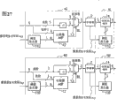
Figure 12 is the block diagram that represents another structure of image processing apparatus according to a second embodiment of the present invention.
Figure 13 is that the process flow diagram of image processing method is processed in the previous stage in the example explanation at image.
Figure 14 is that the process flow diagram of image processing method is processed in the rear one-level in the example explanation at image.
Figure 15 is the block diagram of structure of the image processing apparatus of expression a third embodiment in accordance with the invention.
Figure 16 is the block diagram of another structure of the image processing apparatus of expression a third embodiment in accordance with the invention.
Figure 17 is the block diagram of structure of the image processing apparatus of expression a fourth embodiment in accordance with the invention.
Figure 18 is the circuit diagram of the inner structure of the position optional feature shown in expression Figure 17.
Figure 19 is the tabulation that is illustrated in input signal and output signal in the fourth embodiment of the present invention.
Figure 20 is the tabulation that is illustrated in input signal and output signal in the fourth embodiment of the present invention.
Figure 21 is the tabulation that is illustrated in input signal and output signal in the fourth embodiment of the present invention.
Figure 22 is that the example explanation is based on the type of input signal, by the figure of the variation in the gray level of the execution of the gray level controller shown in Figure 17.
Figure 23 is the block diagram that represents the structure of image processing apparatus according to a fifth embodiment of the invention.
Figure 24 is illustrated in the input signal of the B component in the fifth embodiment of the present invention and the tabulation of output signal.
Figure 25 is illustrated in the input signal of the B component in the fifth embodiment of the present invention and the tabulation of output signal.
Figure 26 is illustrated in the input signal of the B component in the fifth embodiment of the present invention and the tabulation of output signal.
Figure 27 is the block diagram that the image shown in expression Figure 23 is processed the detailed construction of previous stage and the rear one-level of image processing.
Figure 28 represents the tabulation of the input/output signal of the threshold generator shown in example explanation Figure 27.
Figure 29 is the block diagram that represents another structure of image processing apparatus according to a fifth embodiment of the invention.
Figure 30 is the block diagram that represents the structure of image processing apparatus according to a sixth embodiment of the invention.
Figure 31 is the state transition diagram that is illustrated in the transfer in 2 digit counters shown in Figure 30.
Figure 32 is that the example explanation is in the tabulation of the input/output signal of carry generator shown in Figure 30.
Figure 33 is illustrated in input signal in the sixth embodiment of the present invention and the tabulation of output signal.
Figure 34 is illustrated in input signal in the sixth embodiment of the present invention and the tabulation of output signal.
Figure 35 is illustrated in input signal in the sixth embodiment of the present invention and the tabulation of output signal.
Figure 36 is the block diagram that represents the structure of image processing apparatus according to a seventh embodiment of the invention.
Figure 37 is that expression is according to the block diagram of the structure of the image processing apparatus of the eighth embodiment of the present invention.
Figure 38 is that expression is according to the block diagram of the structure of the image processing apparatus of the ninth embodiment of the present invention.
Figure 39 is that expression is according to the block diagram of the structure of the image processing apparatus of the tenth embodiment of the present invention.
Figure 40 is that expression is according to the block diagram of the structure of the image processing apparatus of the 11st embodiment of the present invention.
Figure 41 is that expression is according to the block diagram of the structure of the image processing apparatus of the 12nd embodiment of the present invention.
Figure 42 is the block diagram that schematically shows according to the structure of the image processing apparatus of the 13rd embodiment of the present invention.
Figure 43 is the block diagram that schematically shows according to the structure of the image processing apparatus of the 14th embodiment of the present invention.
Figure 44 is the block diagram of the structure of expression liquid crystal display (LCD).
Figure 45 is the shift register shown in expression Figure 44 and the block diagram of data register.
Figure 46 is the circuit diagram of the inner structure of the selector switch shown in expression Figure 44.
Figure 47 is illustrated among the LCD of Figure 44, and image is processed the figure of the logical organization of previous stage and the rear one-level of image processing.
By the way, mark 1 representation raster image.Mark 1A representation raster image (image).Mark 1B representation raster image (text message).Mark 2 expressions are used for the storer that storage shows image.Mark 3 and 3A presentation video display unit.Mark 4 presentation videos are processed previous stage.Mark 4A represents compressor reducer.One-level after mark 5 presentation videos are processed.Mark 5A represents decompressor.Mark 6 expression storeies use on-off controller.Mark 7 representation raster image transmission ends (first module).Mark 8 representation raster image receiving ends (second unit).One-level after mark 9 expression FRC images are processed.Mark 10 expression liquid crystal display components.Mark 11,11A and 11B represent threshold generator.Mark 12 expression comparers.Mark 13,13A, 13B, 13C, 13D and 51 presentation selectors.Mark 14 and 14 expression position optional features.Mark 15 and 52 expression demultiplexers.Mark 16 expression I/O on-off controllers.Mark 17 expression totalizers.Mark 18 expression quantizers.Mark 19 expression counters.Mark 20 expression carry generators.Mark 21A and 21B represent shift register.Mark 22 expression data registers.Mark 23 expression latchs.Mark 24 expression D/A transducers.Mark 25 expression data line selector switchs.Mark 26 expression memory controllers.Mark 27 expression storage input signal switch controllers.Mark 28 presentation video compositors.Mark 29 expression control signals.Mark 31 expression pixels (pixel).Mark 32 expression thin film transistor (TFT)s.Mark 33 expression data lines.Mark 34 expression gate lines.Mark 50 expression bit plane quantity reduction controllers.
Embodiment
According to principle of the present invention, concerning the image that reduces its bit plane quantity is processed in the noise increase that is called shake by execution, carry out noise and increase the anti-processing of processing in order to increase the bit plane quantity of image, thereby minimize the difference component that occurs owing to increasing jittering noise.By this mode, can suppress granular sensation and pseudo-color.
For example, consider by many-valued dithering process, convert 6 signals to 4 signals, then 4 signal extension are become the situation of 6 signals.In this case, if the dither matrix that is used in the many-valued dithering process is based on orderly shake, need to increase the shake of 6-4=2 position.Therefore, will be increased on the input signal with binary mode 00,01, the jittering component of 10 and 11 expressions or any one of quantity.Can represent many-valued dithering process with following formula.
Y=int((X-D)/4)
Wherein, X is 6 signals of input, and D is jittering component, and the integral part of int (X) expression X.In addition, divided by 4 corresponding to becoming 4 from 6 bit maps.When input signal values is for example 37 when (binary mode 100101), when jittering component is 00, by many-valued dithering process, convert thereof into 9 (1001), and when jittering component is 01, convert thereof into 9 (1001), when jittering component is 10, convert thereof into 8 (1000), and when jittering component is 11, convert thereof into 8 (1000).
Then, 4 signal extension are become 6 signals.By following formula, show the conversion of 6 signals:
Z=4×Y+D+2
, if remove constant 2, form so Y=(Z-D)/4 here, its expression expansion is that the contrary of many-valued dithering process processed.When based on above-mentioned conversion formula, the switching signal value is (during the above-mentioned input signal of 37 (binary mode is 100101), when jittering component is 00, signal is converted into 38 (100110), when jittering component is 01, converts 39 (100111) to, when jittering component is 10, convert 36 (100100) to, and when jittering component is 11, convert 37 (100101) to.Constant 2 in this conversion formula is off-set values of increasing so that the mean value of switching signal can be close to the value of input signal.
By comparing, when according to traditional switch technology, when utilizing many-valued shake to carry out 4 to 6 conversions, when input signal is 00 when jittering component, be converted into 38 (100110), when jittering component is 01, be converted into 38 (100110), when jittering component is 10, be converted into 34 (100010), and when jittering component is 11, be converted into 34 (100010), because the component of 2 of 4 high-orders is attached as 2 of low orders.
From then on be appreciated that according to conversion method of the present invention the signal of changing is near input signal values.That is, according to of the present invention, can suppress granular sensation and pseudo-color.
Incidentally, for example and be not that 6 signals having described raster image convert 4 signals to with limiting, then 4 signal extension are become the situation of 6 signals.4 signal extension can be become 5 signals.In this situation, by utilizing the high-order position executable operations of jittering component separately.More particularly, execution is such as the operation of Z=2 * Y+int (D/2)+1.By this structure, even when 4 signal extension are become 5 signals, also can suppress granular sensation and pseudo-color in the raster image.
In addition, in many-valued dithering process, after deducting jitter value, carry out quantification, then increase jitter value.By increasing jitter value, difference or change near " white " that is in high grade grey level shows in minimum value.Namely, as seeing from Fig. 3 to 5, because owing to increase jitter value, make in the gray level greater than or be higher than all output expressions " white " of the value of expression " white " (gray level 63 among Fig. 3 to 5), so near the minimum value of difference during to be all tones " white ".Because this structure, near " white " shows, minimize this difference that is in high grade grey level, thereby reduce the peculiar granular sensation of shake, and it is not enough to suppress near gray scale distortion or minimizing " white " tone showing.
In the character or geometric figure of similar map, such as the color of " red ", " indigo plant ", " green " and " Huang ", some its component of signals are high grade grey levels, and " white ", and its whole component of signals all are in high grade grey level, usually a large amount of the use.According to the present invention, improved the display quality of this sampled images.This is novelty of the present invention and characteristic aspect or effect, and it can not be obtained by the first prior art.
In addition, according to the present invention, can by carrying out with respect to each pixel (pixel), carry out the quality that the same simple processing with many-valued shake improves image.
About signal structure or the component according to raster image of the present invention, except above-mentioned rgb signal, various signals such as the YCbCr signal that is comprised of luminance signal and color signal and the HSV that is comprised of the hue, saturation, intensity signal, LCH signal etc. all are fit to.
Although many-valued shake has been described as the example that image is processed, has been not limited to use this.In fact, can use any other image to process, as long as can realize above-mentioned effect.Especially, such as relating to when increasing and reduce bit plane quantity, the image processing method that the image of carrying out in opposite mode is processed is effective.
With reference now to figure,, provides the detailed description according to the embodiment of image processing apparatus of the present invention, image transfer apparatus and image processing method.Example illustrates image processing apparatus of the present invention, image transfer apparatus and image processing method in Fig. 6 to 47.
[the first embodiment]
Fig. 6 is the process flow diagram according to the treatment scheme of the image processing method of the first embodiment of the present invention.
Hereinafter, with the image processing method of describing according to this embodiment.When being input to raster image in the image processing apparatus (step S1), reduce the bit plane quantity (step S2) of input raster image.The raster image that reduces its bit plane quantity is stored in (step S3) in storer etc.After this, read the raster image that is stored in the storer, and the bit plane quantity (step S4) that increases raster image.
At this moment wait, preferably carry out the processing that reduces and increase bit plane quantity by less logic element.More particularly, compare with the quantity (quantity of transistor, unit etc.) of logic element that can be by the storer that process to reduce, desired image is processed should comprise enough a small amount of logic element.Usually, be used for reducing and increasing a small amount of logic element of processing requirements of bit plane quantity, therefore, can suitably reduce/increase bit plane quantity.As the processing for reducing bit plane quantity, citation is arranged for " position abandons (bit dropping) " of example, namely " block certain bits ".In this case, needn't calculate or process.
According to above-mentioned image processing method, required memory span is possible in the reduction image Graphics Processing.In addition, carrying out figure place with constant data compression rate (data volume before (data volume after data volume before the compression-compression)/compression) reduces/increases.Therefore, can be so that the compression of images of any type in the image processing apparatus (display system), data of its compression original image are in order to be stored in view data in the storer, and the view data of storing of decompressing is in order to show this image.
In this embodiment, by way of example but be not to have described the processing that between the processing that is used for reducing and increase number of bit-planes execution is stored in the data of raster image storer with limiting.Through having the transfer bus of predetermined bus width, can transmit the data of raster image rather than the data of raster image are stored in the storer.
For example, suppose for the functional unit that reduces number of bit-planes or element with do not have the width that is enough to by its primitive form transmission raster image for increasing the transfer bus between the functional unit of number of bit-planes.In this case, the number of bit-planes of raster image is reduced to the quantity in the ability of transfer bus, and transmit the raster image that its number of bit-planes has been reduced.After this, increase processing by the position, increase the bit plane quantity of raster image, then image is outputed to image display part etc.Therefore, can show raster image in image display part.
As described, according to image processing method, in the time can not processing raster image with its primitive form, by this image processing method, reduce and the increase number of bit-planes, can realize aforesaid effect.
In addition, although hereinafter, the several examples that are used for reducing and increasing the method for number of bit-planes have been described in other embodiments of the invention, the shake that is used for reducing number of bit-planes is adopted in expectation, and carry out for increasing the contrary of shake of number of bit-planes and process, this is because can reach the compressing/decompressing image of minimum deterioration of image quality.
[the second embodiment]
Fig. 7 is the block diagram that schematically shows the structure of image processing apparatus according to a second embodiment of the present invention.With reference to figure 7, process the rgb light grid image 1 of processing in the previous stage 4 from 6 of the every color components of having of computer export at image.The raster image that subsequently, will have 4 of every color components is stored in the storer 2.After this, after processing, image in the one-level 5, converts the raster image with 4 of every color components of storing to 6 of every color components image, and the image display part 3 that image is outputed to 6 demonstrations of energy.Incidentally, Fig. 7 represents the structure of block diagram for a kind of color of R, G and B, and image processing apparatus has the same structure for the parallel connection of other two kinds of colors.
Image is processed previous stage 4 and is comprised threshold generator 11A, comparer 12, selector switch 13 and subtracter.2 of the low orders of 6 gray-scale datas of input raster image 1 are sent to comparer 12, and compare with 2 signals exporting from threshold generator 11A in comparer 12.
Fig. 8 is example explanation for generation of the figure from the method for the output signal of threshold generator.
To be used as threshold value based on the dither matrix of orderly shake here.Threshold generator 11A produces output signal based on the X-Y coordinate figure (x, y) of input pixel.In Fig. 8, [x mod2] expression is when the remainder of the X of pixel coordinate figure (x) divided by 2 time, and [y mod 2] represents when the remainder of the Y of pixel coordinate figure (y) divided by 2 time.According to these [x mod 2] and [y mod 2], obtain output valve.
When A<B, the value of 2 of low orders of wherein inputting 6 gray-scale datas of raster image 1 is A, and the output valve of threshold generator 11A is B, comparer 12 outputs " 1 ", otherwise comparer 12 outputs to selector switch 13 with " 0 " as the SEL signal.The SEL signal is the selection signal of selector switch 13.
With the value of 4 of the high-orders of 6 gray-scale datas of input raster image 1 and from then on deduct 1 value that obtains by subtracter and be input to selector switch 13.When the SEL signal from comparer 12 outputs was " 0 ", selector switch 13 was exported the value of 4 of high-orders instructively, and when the SEL signal is " 1 ", the value that selector switch 13 outputs obtain from subtracter.Therefore, obtain 4 output signals that image is processed previous stage 4.
Fig. 9 is illustrated in the figure that image is processed the frame format of the processing in the previous stage.
In Fig. 9, with respect to each pixel (location of pixels) that is represented by transverse axis, 6 gray-scale datas of input on the left side that will be represented by Z-axis convert 4 gray-scale datas of output of the right expression to.For example, be " 011110 " in " ◆ " expression input gray grade of left location of pixels.Because this value is positioned between threshold value " 011111 " and " 011011 ", with its round-up or round down to the value that represents with the horizontal line between them.On the other hand, " ■ " represents output gray level, and in this case, output gray level is " 0110 ".With respect to each location of pixels, carry out aforesaid operations, thereby convert 6 gray-scale datas of raster image 1 to 4 output gray level.
Incidentally, in the input gray grade value situation identical with threshold value, with input value convert to greater than or close to 4 place values of threshold value.In other words, in the input gray grade value situation identical with threshold value, will be chosen as the output gray level value close to of 4 gray-scale values on the threshold value among the figure of threshold value.
In Fig. 9, to process in the previous stage 4 at image, the threshold value based on the X-Y coordinate figure (x, y) according to the input pixel changes converts 6 gray-scale datas to 4 gray-scale datas.By converting 6 of every color components to every color component 4, reduce the bit plane quantity of raster image, and raster image is stored in the storer 2.
After image is processed, in the one-level 5, convert the raster image with less bits number of planes that is stored in the storer 2 to 6 of every color components image, and send to image display part 3.One-level 5 comprised an optional feature 14 and threshold generator 11B after image was processed.Threshold generator 11B is identical with the structure of threshold generator 11A.
Figure 10 is the circuit diagram of the inner structure of expression position optional feature.
Position optional feature 14 will be by appending to the OR Logic application on 4 signals to produce 5 signals as low-order bit to the value that 4 signals from storer 2 outputs obtain.After this, position optional feature 14 increases from 2 high-order position of threshold generator 11B output by totalizer.In addition, position optional feature 14 will append to from the low-order bit of threshold generator 11B output as on 5 signals of the high-order position that obtains from totalizer 17 in order to produce 6 signals.Therefore, 6 signals are sent to image display part.
Concrete example will be provided.Memory signals be 1000 and threshold signal be that 5 signals that are input to totalizer 11 are 10001, and 1 signal is 1 in 11 the situation.Therefore, totalizer 17 is output as 10010.When the low-order bit signal 1 with threshold signal appended on the output valve, 6 output signals were 100101 so.
Being used as low-order bit by the value that will obtain on OR Logic application to 4 signal here, appends on 4 signals in order to minimize difference between input signal and output signal.Fig. 3 to 5 is expression input signals, be stored in signal (4 place value) in the storer 2 and the tabulation of output signal (6 place value) based on the output valve of threshold generator.
In these figure, decimally number represents the signal value of each input signal and threshold generator.Be stored in 4 gray-scale values of the decimally number expression of each signal indication in the storer, and each output signal represents decimally to count 6 gray-scale values of expression.
As seeing from figure, when input signal was equal to or greater than 7, maximum difference was 2, and when input signal be 6 or more hour, the maximum difference is 3.In addition, Fig. 3 to 5 also represents the difference between output signal, the average output signal value corresponding to each input signal, each mean value and input signal values, and by the standard deviation in the output signal of many-valued shake (prior art).
Difference between mean value and input signal values is less, and the variation that produces in color and the brightness is just less, thereby represents good tone rendering.That is, along with standard deviation diminishes on the whole, reduced granular sensation.Compare with the difference between input signal values with the mean value according to prior art, improved in fact the difference between them of the present invention.In nearly all gray level, reduced standard deviation, and be stable low value.From then on it will be appreciated that according to the present invention, can suppress the aberration and the granular sensation that are produced by prior art.
Incidentally, if the output of threshold generator 11 is combined to form 6 as 2 of low orders and output as the storer 2 of 4 of high-orders, and do not have to realize being used for the OR operation of 4 signals, the difference between mean value and input signal values is-1.5 so.Therefore, compare with the situation of using OR, show color and the brightness aspect more changes.But, compared with prior art, become less with respect to the difference between 2 to 40, two values of input signal.
In addition, with reference to figure 3 to 5, identical signal storage is used for each input signal 0 to 3 in storer, therefore, export identical signal.If need to produce different shades in the gray level corresponding to each input signal, can use the grey level transition of input signal.The grey level transition of input signal refers to for example following converted input signal:
(new input signal)=INT ((input signal before the conversion) * 60/63+3))
Wherein INT (A) is the integral part of A.
In addition, if each the high grade grey level that is desirably in after the above-mentioned processing with respect to all jitter values should be with identical in the past with minimum gray level.This can realize by condition is set, and when wherein for example the signal value in being stored in storer is 0, except the above-mentioned grey level transition of input signal, this jitter value is not increased on the output valve.Obviously, can adopt any other disposal route, as long as satisfy above-mentioned condition.
In addition, be described as comparer 12 and selector switch 13 although image is processed previous stage 4, can have realized by subtracter and quantizer 18, as shown in figure 11, in order to obtain identical output.Quantizer 18 has the function for 4 of the high-orders of directly exporting 6 inputs.
About a series of processing of image processing previous stage 4 and the rear one-level 5 of image processing, see that such as Figure 10 and 11 increase is by the value of the output minimizing of the threshold generator 11 in image processing previous stage 4 in the rear one-level 5 of image processing.By minimizing the impact about the picture quality that is caused by shake, can suppress granularity sensation and pseudo-color.
Incidentally, in this embodiment, in threshold generator, utilize in order shake with limiting by way of example and not.More particularly, by using two-dimentional dither matrix, can realize above-mentioned effect, thus, the vertical and horizontal direction at image repeats identical figure in the little length as one-period.When the cycle of dither matrix diminished, it is large that the frequency of periodic noise becomes, and noise is become visually cannot see.For this reason, expect that the two-dimentional dither matrix of 2 pixel period is for vertical and horizontal direction most.
In addition, threshold generator 11B is identical with the structure of threshold generator 11A.Therefore, can only provide a threshold generator, it switches to 11B from threshold generator 11A, or vice versa, as shown in figure 12.In this case, need to be input to for the output of definite threshold generator 11 control of comparer 12 or position optional feature 14.The example of control method as shown in figure 12.
With reference to Figure 12, I/O on-off controller 16 outputs to selector switch 13A and demultiplexer 15 with control signal SEL2.When I/O on-off controller 16 sent to comparer 12 when the output with threshold generator 11, selecting and exporting " 0 " was SEL2, and when putting the output transmission in place optional feature 14, selected and output " 1 ".
As mentioned above, the image processing apparatus of the second embodiment comprise for carries out image processing in case reduce the image of the bit plane quantity of grating 1 process previous stage 4, be used for memory image and process image that the bit plane quantity of the raster image that the storer 2 and being used for of the output signal (raster image) of previous stage 4 will send from storer 2 reverts to original amount and process after one-level 5, and in each image processing previous stage 4 and the rear one-level 5 of image processing, with opposite mode carries out image processing.By this structure, minimize the impact of relevant picture quality.In addition, can reduce electrical power consumed and die size.
In addition, because by many-valued shake, after image is processed previous stage 4 and image and processed, reduce and the increase number of bit-planes in the one-level 5 respectively, can obtain to have the image processing apparatus of the image processing part spare of simple structure.
Incidentally, can pass through the software carries out image processing.
Figure 13 is the process flow diagram that example key diagram picture is processed the example of image processing method in the previous stage, and Figure 14 is the example of image processing method in the rear one-level is processed in the example explanation according to the image of this embodiment process flow diagram.In Figure 13 and 14, by the operation in the one-level after software carries out image processing previous stage and the image processing, another realizes also unimportant with hardware if only realize in them with software.
Figure 13 is illustrated in when input signal and forms by 6, and the number of bit-planes of signal is b position (b: the image processing method in the time of integer 2 to 6) after the compression.X coordinate with gray-scale signal: I (6), pixel: the Y coordinate of x and pixel: y is input to image and processes in the previous stage (step S11).Subsequently, definition produces the required dither matrix (step S12) of threshold value.Here, take advantage of in four the orderly dither matrix four, adopt the matrix [[0,8,2,10], [12,4,14,6], [3,11,1,9], [1 5,7,13,5]] that is called the orderly dither matrix of Bayer.
Then, based on pixel coordinate value x and y, produce threshold value (step S13).Produce the method for threshold value as shown in the figure.[x mod 4] expression is when the remainder of X coordinate figure x divided by 4 time.In order to produce threshold value corresponding to every units, this is because threshold value changes according to the figure place b of output gray level to dither matrix divided by 2 power.For example, if b=4, threshold value is 2 place values so.Because the dither matrix value is 4 place values, it is by divided by 2^ (4-2)=4, in order to make it become 2 place values.
After this, at step S14, deduct threshold value d from the input gray grade signal, and the intercepting low-order bit.In this example, b=4, and 6-4=2, therefore, 2 of intercepting low orders.Therefore, the output high-order is 4.
In Figure 14, with gray-scale signal: b position I, the X coordinate of pixel: the Y coordinate of x and pixel: y is input to image process after one-level 5 (step S21).In step S22 and 23, carry out in the front described same operation of processing previous stage 4 for image.If input signal I is " 0 ", export so Iout=d.Otherwise, be set to high-order position by I and b is set to low-order bit in step S24 output, and the value that 2^ (5-b) is increased to acquisition it on.This 2^ (5-b) is corresponding to the OR output signal, as shown in figure 10.
By aforesaid algorithm, can realize image processing apparatus, it has the image of carrying out based on software processes, and the structure that equals image processing apparatus shown in Figure 7 aspect quality.
Incidentally, the process flow diagram of Figure 13 and 14 only provides as an example and is non-limiting.Any other process is suitable, as long as it satisfies this embodiment.
[the 3rd embodiment]
Figure 15 is the block diagram of the first example of structure of the image processing apparatus of expression a third embodiment in accordance with the invention.Being different from the second embodiment part according to the image processing apparatus of the 3rd embodiment is to exist for determining directly raster image 1 to be sent to image display part 3 or implementing to select the storer of control to use on-off controller 6 from the selector switch 13B that storer 2 sends to the selector switch 13B of display unit 3 and is used for 5 of after image is processed previous stage 4 and image and processed one-levels raster image 1.
Storer uses on-off controller 6 according to the image that will send to image display part 3, control selector switch 13B.For example, when just showing rest image, image remains unchanged.Therefore, storer uses on-off controller 6 outputs " 1 " in order to show the image that is stored in the storer 2.Therefore, the raster image of one-level 5 outputs sent to image display part 3 after selector switch 13B will process from image.On the other hand, when just showing moving image, storer uses on-off controller 6 that " 0 " is outputed to selector switch 13B so that directly at image display part 3 demonstration raster images 1 and it is not stored in the storer.
According to this structure, can carry out from the demonstration rest image to the switching that shows moving image, and vice versa.In addition, can show rest image by more small-sized chip and electrical power consumed still less.
Figure 16 is the block diagram of the second example of structure of the image processing apparatus of expression a third embodiment in accordance with the invention.With reference to Figure 16, when storer uses on-off controller 16 outputs " 0 ", namely, when directly not having the intervention of storer 2 at image display part 3 demonstration raster images 1, process ON/OFF controller 7 by using, stop the processing in image processing previous stage 4, storer 2 and the rear one-level 5 of image processing.By stopping as mentioned above the processing in image processing previous stage 4, storer 2 and the rear one-level 5 of image processing, can reduce electrical power consumed.
[the 4th embodiment]
Figure 17 is the block diagram of structure that schematically shows the image processing apparatus of a fourth embodiment in accordance with the invention.Be different from the 3rd embodiment part shown in Figure 15 according to the image processing apparatus of the 4th embodiment and be the structure of optional feature 14A, and the gray level controller 7 of the storer gray level control using the output of on-off controller 6 to be imported into to provide in the image display part 3.
Figure 18 is the block diagram of structure that schematically shows the position optional feature of a fourth embodiment in accordance with the invention.Position optional feature 14A with the output combination of the output of storer 2 and threshold generator 11B as 4 of high-orders and 2 of low orders in order to respectively they are outputed to selector switch 13B.Compare with position optional feature 14 according to a second embodiment of the present invention shown in Figure 10, the structure of position optional feature 14A is quite simple.
Figure 19 to 21 is the tabulations that represent input signal in the fourth embodiment of the present invention, are stored in the signal in the storer and process the output signal of rear one-level from image.As seeing from Figure 19 to 21, when the structural change of Figure 10 became the structure of Figure 18, the mean value of output signal value was less than input signal values.This causes showing difference or the variation of the brightness aspect of image when selector switch 13B carries out the demonstration switching.Therefore, demonstration tone or the shade on 7 controls of gray level controller or the change gray level.That is, when storer used on-off controller 6 output " 0 ", gray level controller 7 provided standard grayscale control.On the other hand, when storer used on-off controller 6 output " 1 ", gray level controller 7 was adjusted the output gray level signal, as shown in figure 22, so that it is higher than the output signal shown in Figure 19 to 21 aspect gray level.In this way, even when selector switch 13B has carried out the demonstration switching (in other words, when just using storer 2), can obtain the image of same brightness.
The example of gray level controller 7 comprises the structure look-up table in order to carry out the input signal conversion.In addition, if realize gray level controller 7 with hardware, the reference voltage that can change liquid crystal will use analog power with the LCD (liquid crystal display) that shows image or organic EL (electroluminescence) display during as image display part with box lunch, according to the value of using on-off controller 6 outputs from storer, change the V-T characteristic of liquid crystal.
According to this structure, image processing apparatus can be provided, wherein to compare with the first and second embodiment, one-level 5 was carried out seldom and is processed after image was processed.
[the 5th embodiment]
Figure 23 is the block diagram that schematically shows the structure of image processing apparatus according to a fifth embodiment of the invention.The number of bit-planes that is used for color component R, G and B that is to be stored in the storer 2 according to the image processing apparatus of the 5th embodiment and the 3rd embodiment difference shown in Figure 15 is respectively 4,5 and 3.In this structure, storer has the capacity identical with the fifth embodiment of the present invention.
As described, for G distributes large number of bit-planes, and be that B distributes little number of bit-planes.This is because in many-valued dithering process, and the granular sensation that worsens picture quality mainly is the result of luminance difference rather than aberration.G has maximum effect to luminance component, and B has minimum influence.By this structure, can more suppress granular sensation.Incidentally, in common many-valued dithering process, if bit plane is set as mentioned above, the aberration among the B is increased, thereby worsen the quality of the yellowish pink part of image.
Figure 24 to 26 is illustrated in the fifth embodiment of the present invention, be used for color component B input signal, be stored in the signal of storer and process from image after the tabulation of output signal of one-level.In addition, these figure also represent the difference between output signal, the average output signal value corresponding to each input signal, each mean value and input signal values, and by the standard deviation (prior art) in the many-valued shake output signal.Compare with the standard deviation according to prior art, almost the standard deviation of this embodiment has reduced in all gray levels, and is stable low value.From then on will appreciate that according to this embodiment, even when changing the number of bit-planes that is used for each color component, also can suppress aberration and granularity sensation.
As shown in figure 23, because 4 bit memories are used for the R component of raster image, carry out the same treatment that aforesaid image for the second embodiment is processed previous stage 4 and the rear one-level 5 of image processing.About G component and B component, yet, the structure of threshold generator and send to the quantity of position of each parts or width aspect there are differences.Figure 27 presentation video is processed the structure that previous stage 4G and 4B and image process rear one-level 5G and 5B.In Figure 27, threshold generator 11G and 11B produce output signal by the production method shown in Figure 28.
By this structure, can reduce the luminance difference in the demonstration of RGB color.In addition, can obtain to have the image of minimum granularity sensation, aspect quality, can compare with 6 demonstrations of order.
In addition, in Figure 23, can only provide a threshold generator, the same with the second embodiment of the present invention.Figure 29 represents the example of this structure.Threshold generator 11 shown in Figure 29 adopts the production method that is used for the threshold generator 11B shown in Figure 28, and utilizes 2 conducts of high-order to be used for the output of R component and only 1 high-order position output that acts on the G component.This has eliminated with respect to color component R, G and B each, and the needs of threshold generator 11 are set, thereby has increased efficient.
[the 6th embodiment]
Described image processing apparatus, its raster image that will have 6 of every color components is stored in 4 bit memories, and on the basis of its data, shows high quality graphic at the image display that can show the image with 6 of every color components.Hereinafter, will describe allowing to utilize FRC (frame frequency control), and have in demonstration on the image display part of image of 4 of every color components and can show 6 image processing apparatus.
FRC changes tone for showing in the image processing apparatus that limits at tone by periodic variation, the method for the quantity of producible tone or shade on the increase gray level.For example, in the image processing apparatus that can show the image with 0 to 15 grade of gray level, if the shown tone of periodic variation by being 1 cycle with 4 frame definitions, resembles 14,14,14,15, can realize so the demonstration of 15 * 4+1=61 tone.This is equivalent to 6 demonstrations basically.
Figure 30 is the block diagram that schematically shows the structure of image processing apparatus according to a sixth embodiment of the invention.One-level 5 after one-level 9 replaces image among Fig. 7 to process after being different from the second embodiment part shown in Fig. 7 and being to exist the FRC image to process according to the image processing apparatus of the 6th embodiment, and will represent that the VSync that frame begins is input in the rear one-level 9 of FRC image processing, and image display part 3A can show the image with 4 of every color components.Incidentally, for the sake of simplicity, only see in the drawings the piece of R, G and B.
Hereinafter, will mainly describe the FRC image and process rear one-level 9.One-level 9 comprised for the X-Y coordinate based on pixel after the FRC image was processed, produce threshold value threshold generator 11B, be used for counting VSync 2 digit counters 19, be used for the output based on threshold generator 11B and 2 digit counters 19, produce the carry generator 20 of carry, and be used for according to carry value, definite output that will output to by adding 1 value that obtains storer 2 still outputs to this output valve the selector switch 13 of image display part 3 instructively.
After this, selector switch 13 is selected the signal with output based on carry value.When carry value is " 0 ", selector switch 13 will output to from the output valve of storer 2 image display part 13.On the other hand, when carry value is " 1 ", selector switch 13 will output to by the value that adds 1 acquisition the output valve from storer 2.
Figure 33 to 35 is illustrated in the sixth embodiment of the present invention, input signal, the tabulation that is stored in the signal in the storer and processes the output signal of rear one-level 9 from the FRC image.In addition, these figure also represent between output signal, the average output signal value corresponding to each input signal, each mean value and input signal values difference and by the standard deviation in the input signal of many-valued shake (prior art).Although each output signal is 4 actual bit, also utilize the value by 4 to 6 conversion acquisitions in order to can mutually compare difference between input and output signal here.Output signal from one-level 9 after the processing of FRC image is for the mean value of processing 4 frames (1 cycle) of rear one-level 9 acquisitions by the FRC image.Compare with the standard deviation according to prior art, almost the standard deviation of this embodiment reduces by 1 in all gray levels, and is stable low value.Standard deviation also has the comparison with Fig. 3 to 5.From then on will appreciate that according to the present invention, by 4 bit memories and 4 displays, can obtain aspect quality the image with 6 bit image equivalences.
According to this structure, image processing apparatus can be provided, to compare with the image that obtains by traditional many-valued shake, it can produce higher-quality image, and is different from and utilizes traditional FRC, does not need 6 bit memories.
[the 7th embodiment]
Hereinafter, the seventh embodiment of the present invention will be described.Figure 36 is the block diagram of example that represents the structure of image processing apparatus according to a seventh embodiment of the invention.Be different from the 3rd embodiment part according to the image processing apparatus of the 7th embodiment and be to exist compressor reducer 4A and decompressor 5A, one-level 5 after replacing image to process previous stage 4 and image processing.
Storer uses on-off controller 6 according to the image that will send to image display part 3, control selector switch 13B.For example, when just showing rest image, image remains unchanged.Therefore, storer uses on-off controller 6 outputs " 1 " in order to show the image that is stored in the storer 2.Therefore, selector switch 13B will send to image display part 3 from the raster image of decompressor 5A output.On the other hand, when just showing moving image, storer uses on-off controller 6 that " 0 " is outputed to selector switch 13B so that directly at image display part 3 demonstration raster images 1 and it is not stored in the display 2.
According to this structure, can carry out from the demonstration rest image to the switching that shows moving image, and vice versa.In addition, to show rest image with more small-sized chip and electrical power consumed still less.In this demonstration is switched, do not require such as required specific compression/decompression processes in the one-level 5 after processing previous stage 4 and image at image and processing, and any compressor reducer 4A and decompression 5A be suitable for, have suitable effect.
More particularly, compressor reducer 4A and decompressor 5A do not need that the picture signal execution that is input to the image in the storer 2 and from then on reads is had the compression/decompression processes of special relationship (for example, should use identical two-dimentional dither matrix).
For example, compressor reducer 4A can use different two-dimentional dither matrixs with decompressor 5A, carries out compression/decompression processes in order to carry out to be used for respectively to the picture signal that is input to storer 2 with from the picture signal that storer 2 is read.
In addition, obviously, compressor reducer 4A and decompressor 5A can carry out other compression/decompression processes in the situation of not using two-dimentional dither matrix, in order to realize and aforesaid identical effect.
[the 8th embodiment]
Hereinafter, the eighth embodiment of the present invention will be described.Figure 37 is that expression is according to the block diagram of the example of the structure of the image processing apparatus of the eighth embodiment of the present invention.The structure according to the image processing apparatus of image processing apparatus in comprising the 7th embodiment of the 8th embodiment, further comprise and process ON/OFF controller 7.When storer uses on-off controller 6 output " 0 ", that is, when directly not having the intervention of storer 2 at image display part 3 demonstration raster images 1, process the processing that ON/OFF controller 7 stops among compressor reducer 4A, storer 2 and the decompressor 5A.
In the image processing apparatus of this embodiment, when storer uses on-off controller 6 output " 0 ", that is, when not using storer 2, process the processing that ON/OFF controller 7 stops among compressor reducer 4A, storer 2 and the decompressor 5A.In this way, can realize the identical effect that obtains such as the image processing apparatus by the tenth embodiment.In addition, can reduce electrical power consumed.
[the 9th embodiment]
Hereinafter, the ninth embodiment of the present invention will be described.Figure 38 is that expression is according to the block diagram of the example of the structure of the image processing apparatus of the ninth embodiment of the present invention.Be different from that the 3rd embodiment part is that storer 2 has and can be by the resolution of X*Y pixel according to the image processing apparatus of the 9th embodiment, the capacity (that is, the image of storer 2 energy storing X * Y pixels) that shows image display part 3 equivalences of the image with 6 of every color components.
In this description, " resolution of display unit " refers to the maximum pixel amount that display unit (for example image display part 3) can once horizontal and vertical represents on screen.If for example the resolution of display unit is 640 to multiply by 480 (pixels), its have in a horizontal direction 640 pixels and in the vertical direction in have 480 pixels.That is, display unit is had the ability once to show on screen by being less than 640 and be multiply by 480 images that form.
In addition, " resolution of image " refers to form the sum of all pixels of image, and the product that is expressed as the quantity of pixel in pixel in the vertical direction and the horizontal direction.For example, if the resolution of image is 640 to multiply by 480 (pixels), image take to represent with 640 pixels in a horizontal direction and in the vertical direction in the zone of shape of the rectangle that represents of 480 pixels.
In this case, as shown in figure 38, if its resolution is input as raster image 1 for the image (X*2Y) of the twice of the resolution (X*Y) of image display part 3 in the vertical direction, compressibility compressed image with 1/2, namely, process in the previous stage 4 at image, make the number of bit-planes of image reduce half.Therefore, whole image can be stored in the storer 2.In other words, being input as image raster image 1, that be comprised of the pixel of the resolution twice of image display part in the vertical direction 3 can whole being stored in the storer 2.After this, after processing, image in the one-level 5, expands the arbitrary region in the X*Y zone of input picture.Therefore, image display part 3 can show that its resolution is higher than or greater than the arbitrary region of the resolution of display unit 3.In this way, even the image that is stored in the storer 2 is high-definition picture, such as rolling image (that is the image that, is formed by the pixel greater than the resolution of image display part 3), in each frame period, can not receive image ground from the outside and show this image.
Show that in the intervention that does not have storer 2 highest resolution of input picture is X*Y in the situation of image.More particularly, if be input as the image of raster image 1 less than the zone of X*Y pixel, storer uses on-off controller 6 that " 0 " is outputed to selector switch 13B so that in the situation of the intervention that does not have storer 2, direct demonstration raster image 1 on image display part 3.
Although by way of example rather than two images citations all over the screen that will be close to with limiting be input picture, when being input to two or more different images in the image processing apparatus, can realize identical effect obviously.
For example, under two raster images that will be made of the X*Y pixel are stored in situation in the storer 2, by processing in the previous stage 4 at image, compress them with previously described identical mode, each image can be stored in the storer 2.In addition, after reading them from storer 2 and after image is processed, expanding them the one-level 5, can show each raster images in image display part 3.
As mentioned above, according to this embodiment of the present invention, when the resolution aspect being higher than or greater than image display part 3m (m: when positive count) doubly image is input as raster image, input picture is compressed into the m of its original size/one, and is stored in the storer 2.Therefore, even the raster image that is comprised of the pixel greater than the resolution of image display part 3 when input picture, energy be stored in this image in the storer 2.
In addition, expansion or the decompression of the picture signal by carrying out the image that is used for being stored in storer 2 in the one-level 5 after image is processed can show that its resolution is higher than or greater than the arbitrary region of image of the resolution of display unit 3.
In addition, even the image that is stored in the storer 2 is high-definition picture, such as the rolling image (namely, the image that is formed by the pixel of the resolution that is higher than image display part 3), in each frame period, not receiving in the situation of image from the outside, can show image.
[the tenth embodiment]
Hereinafter, the tenth embodiment of the present invention will be described.Figure 39 is that expression is according to the block diagram of the example of the structure of the image processing apparatus of the tenth embodiment of the present invention.
Be different from the 9th embodiment part according to the image processing apparatus of the tenth embodiment and be, further have at image process the selector switch 13C of 2 of previous stage 4 and storeies, the selector switch 13D after image is processed between one-level 5 and selector switch 13B and the storer input signal switch controller 27 that is used for control selector switch 13C and 13D.
The resolution of storer input signal switch controller 27 reference-input signals etc., selecting or determining to be stored in image in the storer 2 is compressed image or compressed image not.In the following description, although select compressed image or compressed image not with reference to resolution, data volume such as number of bit-planes that also can reference picture is carried out the selection between them.
For example, when storer 2 was used for raster image 1 that storage forms by the X*Y pixel, storer input signal switch controller 27 outputed to selector switch 13C and 13D with " 0 ", and storer use on-off controller 6 outputs to selector switch 13B with " 1 ".Therefore, compressed image is not stored in the storer 2, and shows in image display part 3.
On the other hand, when storer 2 was used for raster image that storage forms by the X*2Y pixel, storer input signal switch controller 27 outputed to selector switch 13C and 13D with " 1 ", and storer use on-off controller 6 generals " 1 outputs to selector switch 13B.Therefore, will process the image that compresses in the previous stage 4 at image is stored in the storer 2.After this, read image in order to after image is processed, expand the one-level 5 from storer 2, and the image of expanding is presented on the image display part 3.
Incidentally, be not used in the situation of storing the raster image 1 that is formed by the X*Y pixel at storer 2, storer uses on-off controller 6 that " 0 " is outputed to selector switch 13B so that with the same in the 9th embodiment, in the situation of the intervention that does not have storer 2, on image display part 3, directly show raster image 1.
By this structure, can with compressed image or not compressed image be chosen as the image that will be stored in the storer 2.When the size that will show image was placed on before the picture quality, by selecting compressed image, the image that can not once show at screen can be stored in the storer such as map.On the other hand, if when for example showing the rest image of natural image, the priority of specify image quality is selected not compressed image.Therefore, can provide and to improve the suitable of picture quality and memory efficiency or image processing apparatus flexibly.
[the 11 embodiment]
Hereinafter, the 11st embodiment of the present invention will be described.Figure 40 is that expression is according to the block diagram of the example of the structure of the image processing apparatus of the 11st embodiment of the present invention.In this embodiment, be divided into image 1A and text message 1B as the raster image 1 of original image, then be input to image processing apparatus.
Be different from the 9th embodiment part according to the image processing apparatus of this embodiment and be to exist image synthesizer 28.The image 1A that image synthesizer 28 its bit planes of generation are increased in the one-level 5 after image is processed and the composograph of text message 1B.
Putting forward a hypothesis is divided into the situation of two-layer raster image, input picture 1A (pixel quantity: X*Y; 6) and text message 1B (pixel quantity: X*Y; 1).When not compressing, with respect to the X*Y pixel each, their composograph comprises 6+1=7 bit data.Owing to each with respect to the X*Y pixel of storer 2, can store maximum 6 bit data, unpressed composograph can not be stored in the storer 2.
In this case, storer uses on-off controller 6 that " 1 " is outputed to selector switch 13B in order to image 1A is input in the image processing previous stage 4.In image is processed previous stage 4, use with in front described identical mode, compressed image 1A is in order to make the number of bit-planes of image 1A reduce to " 5 " from " 6 ".Therefore, with respect to the X*Y pixel each, having reduced the data of image 1A of its number of bit-planes and the sum of text message 1B is 5+1=6, therefore, they can be stored in the storer 2.
After this, read the image 1A that its number of bit-planes is reduced to " 5 " and after image is processed, use identical as mentioned above mode to expand so that number of bit-planes is increased to " 6 " from " 5 " the one-level 5 from storer 2.The image 1A that its number of bit-planes that image synthesizer 28 generations are read from storer 2 has increased the one-level 5 after image is processed and the composograph of text message 1B.Show composograph in image display part 3.
As mentioned above, according to this embodiment of the present invention, raster image is divided into two-layer, and is input in the image processing apparatus.Unless when compressing it, otherwise this raster image can not be stored in the storer 2 time, compress the data of at least one layer or reduce number of bit-planes in order to this image is stored in the storer 2.After the number of bit-planes that the data compressed of expansion or increase reduce, make up two-layer.Therefore, can show composograph.
For example, when image 1A is common 6 bit images and text message 1B when being 1 bit image, as shown in figure 40, can be realized by image synthesizer 28 the overlapping demonstration of texts.In addition, do not need to arrange new storer and show superimposed images.
In addition, the image processing apparatus of this embodiment can change image 1A and text message 1B individually.For example, suppose that image 1A is that rest image and text message 1B are the clocks for the expression time, (for example, per second or per minute) obtains text message 1B and is stored in the storer 2 so that the processing of processing in previous stage 4, storer 2 and the rear one-level 5 of image processing by image distributes at regular intervals.Therefore, when when image display part 3 shows raster image 1, can reduce electrical power consumed.
Incidentally, in this embodiment, can be form raster image two-layer with a plurality of tone images and text message citation by way of example rather than with limiting.As another example, can be fit to the overlapping demonstration of two images.
[the 12 embodiment]
Hereinafter, the 12nd embodiment of the present invention will be described.Figure 41 is that expression is according to the block diagram of the example of the structure of the image processing apparatus of the 12nd embodiment of the present invention.In this embodiment, the signal that be used for to show raster image 1 is divided into two-layer, is used for image 1A and the control signal 29 of each pixel, and is input in the image processing apparatus.
Being different from the 9th embodiment part according to the image processing apparatus of the 12 embodiment is in the situation that image 1A and control signal 29 not have to compress, in the time of can not being stored in the storer 2, compressed image 1A or reduce its number of bit-planes in order to they are stored in the storer 2, and based on control signal 29, show the image that obtains by the number of bit-planes of expanding compressed image or increase minimizing in image display part 3.
The input that puts forward a hypothesis is used for showing the signal that has been divided into two-layer raster image 1, the image 1A (pixel quantity: X*Y that is used for each pixel; 6) and the situation of control signal 29 (1).With respect to the X*Y pixel each, the total amount of the data of image 1A and control signal 29 is 6+1=7 bit data.Owing to each with respect to the X*Y pixel of storer 2, can store maximum 6 bit data, the signal that is used for showing raster image 1 can not be stored in the storer 2 in the situation that does not have compression.
In this case, storer uses on-off controller 6 that " 1 " is outputed to selector switch 13B and processes previous stage 4 in order to will be input to image for the signal that shows raster image 1.Process in the previous stage 4 at image, use with identical as previously mentioned mode compressed image 1A in order to make the bit plane quantity of image 1A reduce to " 5 " from " 6 ".Therefore, with respect to each of X*Y pixel, being used for the image 1A that reduces its number of bit-planes of each pixel and the data total amount of control signal 29 is 5+1=6 bit data, therefore, they can be stored in the storer 2.
After this, read the image 1A that its number of bit-planes reduces to " 5 " from storer 2, and with identical as mentioned above mode, after image is processed, expand in order to make number of bit-planes be increased to " 6 " from " 5 " in the one-level 5.Based on the control signal 29 that is used for each pixel of reading from storer 2, show the image 1A that has increased its number of bit-planes in image display part 3.
As mentioned above, according to the 12nd embodiment of the present invention, will become at least one image and at least one control signal for the division of signal that shows raster image 1, and be input in the image processing apparatus.When do not having the compression situation under, in the time of they can not being stored in the storer 2, compress at least one image or reduce its number of bit-planes so as with signal storage in storer 2.Based on control signal, can show the image of the number of bit-planes acquisition that reduces by expansion compressed image or increase.
In addition, identical with the 11 embodiment, the image processing apparatus of this embodiment can change image 1A and control signal 29 independently.For example, the processing after can processing previous stage 4, storer 2 and image and process by image in the one-level 5 is only upgraded control signal 29 in order to distribute.Therefore, when when image display part 3 shows raster image 1, can reduce electrical power consumed.
[the 13 embodiment]
In the first to the 12 embodiment, described and have storer, allow to reduce memory span and electrical power consumed, and can provide can with the image processing apparatus by the suitable picture quality of the picture quality of existing techniques in realizing.In addition, according to the of the present invention the 13 and the 14 embodiment, raster image is sent to second unit from first module, wherein can reduces transmission capacity.Hereinafter, this structure will be described.
Figure 42 is the block diagram that schematically shows according to the structure of the image transmission of the 13rd embodiment of the present invention.With reference to Figure 42, comprise for the first module 7 that sends raster image and be used for receiving the second unit 8 of this raster image according to the image transfer apparatus of the 13rd embodiment of the present invention.In first module 7, process previous stage 4 places at image, the raster image 1 that will have 6 of every color components converts the image with 4 of every color components to, and sends to second unit 8.In second unit 8, one-level 5 places after image is processed will revert to the image with 6 of every color components from the raster image that first module 7 receives, and output to image display part 3.Here, one-level 5 had the identical structure that is used for as previously mentioned above-described embodiment after image was processed previous stage 4 and image is processed.
By this structure, raster image can be sent to second unit from first module, and not reduce significantly picture quality, and by minimum transmission capacity, can the carries out image transmission.This form enough maybe will not reduce in the situation of quantity of the transfer bus between first module and second unit very favourable concerning image in transmission capacity.
Incidentally, the second unit 8 that provides for the image transmission of this embodiment also represents image received device according to a preferred embodiment of the invention.
The raster image that reduces its number of bit-planes is compared in image received device reception of the present invention with original image, and as second unit 8, increases the number of bit-planes of the image that receives.Therefore, can be created in the image that the quality aspect can be compared with original image.In addition, because in transmission ends, the number of bit-planes of image is reduced to less than the quantity of the number of bit-planes of original image, image received device can receive image effectively.
For example, by having the device for the transfer bus that receives image, reception has in the situation of raster image of 6 of per 6 color components (18 altogether), this transfer bus only is 16 bit wides, the number of bit-planes that reduces raster image in transmission ends has the still less raster image of number of bit-planes so that this device can receive, and after this, this device increases the number of bit-planes of image.Therefore, this device can be received in each color component of image that qualitatively can be suitable with original image concurrently.
[the 14 embodiment]
Figure 43 represents the image transmission according to the 14th embodiment of the present invention.This image transmission comprises for the first module 7 that sends raster image and for second unit 8a, the 8b and the 8c that receive raster image.Incidentally, the transfer bus between first module 7 and second unit 8a, 8b and 8c has respectively 15,12 and 9 s' highway width.
In addition, second unit 8b will have 4 of every color components among the one-level 5b after image is processed raster image reverts to the image with 6 of every color components, and second unit 8c will have the raster image of 3 of every color components and revert to the image with 6 of every color components among the one-level 5c after image is processed.In other words, second unit 8b uses the mode identical with second unit 8a to operate with 8c.
Will be according to the operation of this embodiment Description Image conveyer.For example, description raster image 1 is sent to the situation of second unit 8a.In image is processed previous stage 4, process the raster image with 6 of every color components in case produce have respectively 5 of every color components, 4 and 3 s' raster image.Number of bit-planes reduction controller 50 control selector switchs 51 are so that input is suitable for the raster image of receiving element, that is, the raster image that will have 5 of every color components is input to demultiplexer 52.At this moment, number of bit-planes reduction controller 50 sends to selector switch 51 with control signal " a ".Because the control signal of exporting from number of bit-planes reduction controller 50 is " a ", therefore, the raster image that is input to demultiplexer 52 is outputed to the transfer bus that leads to second unit 8a.
As mentioned above, can according to receiving element, determine the number of bit-planes that is reduced by raster image according to the image transfer apparatus of this embodiment.Therefore, the raster image corresponding to the number of bit-planes of the highway width of transfer bus can be sent to receiving element and image and process after one-level 5a to the capacity of 5c.Therefore, improve the efficient of transmission capacity.
[the 15 embodiment]
Reduce die size and electrical power consumed owing to the present invention is directed to, do not need image processing part spare to carry out the processing of any complexity, and have simple structure.Therefore, the present invention can realize above-mentioned effect when on the driver that is applied to the display unit with internal memory and the controller chip.The present invention can be applicable to arrange in glass substrate many silicon circuits of these drivers and controller in addition.
Figure 44 represents to form the liquid crystal display (LCD) of image processing part spare and driving circuit parts in glass substrate by using many silicon thin film transistors circuit.Input signal is comprised of every color component R, G and 6 of B, and storer has the capacity of 4 of every color component R, G and B, and output is 6 of every color component R, G and B.Raster image 1 from the outside is presented on the liquid crystal display component 10.Liquid crystal display component 10 comprises picture element matrix 31, thin film transistor (TFT) 32, a plurality of data line 33 and a plurality of gate line 34, and they are positioned to the lattice that forms with respect to every pair of pixel 31 and thin film transistor (TFT) 32, and each is connected to thin film transistor (TFT) 32.According to the signal from gate line 34, when thin film transistor (TFT) 32 has been input to the ON state, the signal that is connected to the data line 33 of thin film transistor (TFT) 32 is written to each pixel.
Make raster image 1 send to image and process previous stage 4 and data register 22.Be input to image and process the image that the raster image of previous stage 4 stands to be used for as mentioned above the first to the 12 embodiment and process, and be stored in and have 12 the storer 2 of capacity altogether for color component R, G and B.After this, if necessary, from storer 2 sense datas, and after image is processed carries out image processing in the one-level 5.The output of image being processed rear one-level 5 sends to selector switch 13B.The image of processing rear one-level 5 with in the past described identical mode carries out image processing previous stage 4, storer 2 and image with being used for the first to the 12 embodiment here, is processed.Therefore, after control signal is input to image and processes previous stage 4 and image and process during one-level 5, when data being write or during readout memory 2, needing the X-Y coordinate of pixel.Incidentally, control signal is not limited to the X-Y coordinate of pixel.Can use to derive from it control signal of the X-Y coordinate of pixel, such as VSync, Hsync and CLK.Memory controller 26 switches between reading and writing, and control is used for the address of the data I/O of storer 2.X-Y coordinate to major general's pixel is input to memory controller 26 and image processing previous stage 4 and the rear one-level 5 of image processing.
Figure 45 is the shift register 21A of expression LCD and the circuit diagram of data register 22.About being input to the raster image of data register 22, on the basis from the output signal of separately shift register (S/R) 21A, sequentially storing 6 bit data, and latched by latch 23.The output of latch 23 is sent to selector switch 13B.
Figure 46 is the circuit diagram of structure of the selector switch 13B of expression LCD.Selector switch 13B according to whether show process by image after one-level 5, be stored in the data that image in the storer 2 selects to send to DAC24, or based on use the control data of on-off controller 6 directly to show image from the outside from storer.DAC24 will convert simulating signal to from the digital signal of 6 of the every color components of having of selector switch 13B, and signal is outputed to the desired data line by data line selector switch 25.
By the thin film transistor (TFT) 32 corresponding to the gate line 34 of being selected by shift register 21B, the output of data line selector switch 25 is sent to liquid crystal display component 10 and is written to pixel 31.
By this structure, according to the 15th embodiment of the present invention, can obtain to have on glass substrate, be used for as previously mentioned the LCD of the built-in image processing circuit of the first to the 12 embodiment.The image that can be formed by less transistor separately in addition, is processed previous stage 4 and the rear one-level 5 of image processing.
Figure 47 represents for becoming the image of 6 signals to process the example of the logical organization of previous stage 4 and the rear one-level 5 of image processing at 4 bit memories and with this signal extension 6 signal storage.In Figure 47, one-level 5 only comprised 2 inputs/3 input NADN circuit and phase inverters after image was processed previous stage 4 and image processing.From then on the size that will appreciate that image processing circuit is enough to less than the memory block, and the size that can reduce circuit block.
Although described the present invention with reference to specific exemplary embodiment, those skilled in the art will recognize in the situation that does not deviate from the spirit and scope of the present invention, it is not limited to this but various changes and improvements can be arranged.
For example, in the above-described embodiments, will use two-dimentional dither matrix and be implemented as the method for image processing based on the many-valued dithering process of the position additional treatments of two-dimentional dither matrix.Yet, the invention is not restricted to these embodiment, but be enough to as long as can suppress above-mentioned pseudo-profile, pseudo-color and granular sensation.
In addition, in the above-described embodiments, when reducing the number of bit-planes of raster image, carry out many-valued dithering process by using two-dimentional dither matrix, and when increasing number of bit-planes, based on the two-dimentional dither matrix that is used for many-valued dithering process, execute bit additional treatments.Yet, can use other image processing methods, by other image processing methods, when increasing and reduce number of bit-planes, with opposite mode carries out image processing, for example by using randomized jitter to replace two-dimentional dither matrix in order to carry out many-valued dithering process.
In addition, in a second embodiment, provided the description of the structure of the situation of passing through the software carries out image processing.Can pass through at image processing apparatus with according to the software carries out image processing in the image transfer apparatus of other embodiment, identical with the second embodiment.
As described, the present invention can have various changes and improvements.
Industrial usability
As mentioned before, according to the present invention, by less logic element, can compression/de-compression will send to the bitmap images of display unit, thereby allow to reduce memory capacity and transmission capacity.
In addition, according to the present invention, compare with many-valued shake, the image and the difference between original image that have stood an additional treatments are very little.Therefore, can suppress granular sensation and the pseudo-color when very large difference is arranged, observed, and can realize high-quality display.
In addition, according to the present invention, for example, when just showing rest image, show compressed image, and when just showing moving image, do not carry out image to process, directly show image.Owing to when showing moving image, can under the intervention that does not have storage (for example storer), show image, can reduce electrical power consumed by the operation that stops storer.
In addition, according to the present invention, in the situation of overlapping demonstration, make 1 of natural image compression/de-compression, and 1 bit capacity that obtains is used for text message.Therefore, can in the situation of any increase that does not have memory capacity, carry out overlapping.
Further, exceed in demonstration in the situation of image of ultimate resolution of display unit, such as map, by the compression/de-compression number of bit-planes, can come memory image with the memory capacity of deficiency.Therefore, can be in situation about again not obtaining from the image of outside, can be at the display image that rolls, this has reduced with image and has shown relevant electrical power consumed.
Further, according to the present invention, can realize image transfer apparatus and image processing method for the efficient that improves transmission capacity.For example, through the transfer bus of 16 bit wides only, transmit in the situation of the rgb light grid image (18 altogether) with 6 of every color components, by reducing number of bit-planes, Compressed grating image.Therefore, can the parallel transfer data.
Further, according to the present invention, can realize the image received device for the capacity that improves the transfer bus that is used for the reception image.
In other words, can reduce for the quantity of the transfer bus that receives image and improve transfer efficiency, this is because image received device receives the image that its number of bit-planes has been reduced to less than the quantity of the number of bit-planes of original image.In addition, by increasing the number of bit-planes of the image receive, can produce qualitatively can be suitable with original image image.
In addition, according to the present invention, form in the display unit of driving circuit at substrate (for example glass substrate), by identical method, can form image processing apparatus at substrate.Therefore, by the present invention is applied to display unit, because less storer can reduce the size of display unit, and can also reduce electrical power consumed.
Claims (41)
1. image processing apparatus reduces the number of bit-planes as the raster image of original image, and after this, makes the number of bit-planes of the minimizing of described raster image be increased to the quantity of the number of bit-planes that is equal to or less than described original image, comprising:
The first image processing apparatus is used for by using two-dimentional dither matrix, carrying out many-valued dithering process when reducing the number of bit-planes of described raster image; And
The second image processing apparatus, described the second image processing apparatus is characterised in that and is configured for: when the number of bit-planes of the minimizing that increases described raster image, each pixel execute bit operation to the raster image that reduces its number of bit-planes, described bit manipulation is as a value that obtains of the gray level of the additional raster image by the OR Logic application having been reduced its number of bit-planes by described the first image processing apparatus to expression of low-order bit, and after this, by will with the X-Y coordinate figure (x of pixel, y) high-order position of corresponding jitter value is added on the result of described bit manipulation, and the low-order bit of additional described jitter value subsequently, based on the two-dimentional dither matrix that is used by described the first image processing apparatus, execute bit additional treatments.
2. image processing apparatus as claimed in claim 1, wherein
When the number of bit-planes of the minimizing that increases described raster image, described the second image processing apparatus is based on the two-dimentional dither matrix that is used by described the first image processing apparatus and reduced the gray level of the raster image of its number of bit-planes, carries out frame frequency control processing so that the periodic variation tone.
3. image processing apparatus as claimed in claim 2 wherein, through having the transfer bus less than the highway width of the number of bit-planes of described original image, transmits the raster image that has reduced its number of bit-planes.
4. image processing apparatus as claimed in claim 2 further comprises:
Storer is used for storing the described data that reduce the raster image of its number of bit-planes by described the first image processing apparatus; Wherein:
Described the second image processing apparatus read be stored in the described raster image in the described storer data to increase described number of bit-planes.
5. image processing apparatus as claimed in claim 2, wherein, described the first and second image processing apparatus are carried out in the following manner described image and are processed, described mode so that, the maximal value of the component of described raster image and minimum value were with identical in the past after described image was processed.
6. image processing apparatus as claimed in claim 2, wherein, described the second image processing apparatus is formed on the substrate, forms the driving circuit of display at described substrate.
7. image processing apparatus as claimed in claim 2, wherein, described the first image processing apparatus is formed on the substrate, forms the driving circuit of display at described substrate.
8. image processing apparatus as claimed in claim 2, wherein
Described the second image processing apparatus increases off-set value so that the difference between the mean value of all jitter values of the signal value of described original image and the described raster image that has increased its number of bit-planes will be minimum value.
9. image processing apparatus as claimed in claim 1, minimizing is as the number of bit-planes of the first raster image of original image, and after this, the quantity that the number of bit-planes of the minimizing by making described raster image is increased to the number of bit-planes that is equal to or less than described original image produces the second raster image, wherein
When the number of bit-planes of the minimizing that increases described raster image, described the second image processing apparatus is based on the two-dimentional dither matrix that is used by described the first image processing apparatus and reduced the gray level of the raster image of its number of bit-planes, the execute bit additional treatments; And described image processing apparatus further comprises:
Selecting arrangement is used for selecting described the first raster image or described the second raster image, and exports selected image, wherein:
By described selecting arrangement, when described original image is rest image, selects described the second raster image, and when described original image is moving image, select described the first raster image.
10. image processing apparatus as claimed in claim 9 further comprises:
Storer is used for storage by the data of the described raster image of described the first image processing apparatus acquisition, wherein:
Described the second image processing apparatus is read the data of the Compressed grating image that is stored in the described storer with carries out image processing.
11. image processing apparatus as claimed in claim 9, wherein
Described the second image processing apparatus increases off-set value so that the difference between the mean value of all jitter values of the signal value of described original image and the described raster image that has increased its number of bit-planes will be minimum value.
12. image processing apparatus as claimed in claim 9 compresses the data as the first raster image of original image, and after this, by the data of decompression raster image, produces the second raster image, wherein
Described the first image processing apparatus compresses the data of described the first raster image;
Described the second image processing apparatus is based on the gray level of the packed data of the first raster image, and the data by described the first image processing apparatus compression of decompressing are in order to produce described the second raster image.
13. image processing apparatus as claimed in claim 1 wherein, is stored in input image data in the storer, and based on the described view data of reading from described storer, shows image in designated display, further comprises:
Be used for institute's Compressed grating image is stored in the device of described storer; And
Be used for described the second raster image is outputed to the device of described display, wherein:
Described the first image processing apparatus compression is as the first raster image of original image, to produce the Compressed grating image;
Described the second image processing apparatus is read the Compressed grating image that is stored in the described storer, and based on the gray level of described Compressed grating image, the described Compressed grating image that decompresses is to produce the second raster image; And
When the data volume of described the first raster image exceeds the capacity of described storer, produce described Compressed grating image.
14. image processing apparatus as claimed in claim 13, wherein, described the first and second image processing apparatus are so that the mode of the maximal value of the component of the maximal value of the component of described the second raster image and minimum value and described the first raster image and minimum value coupling is carried out described image processing.
15. image processing apparatus as claimed in claim 13, further comprise selecting arrangement, be used for when in the capacity of data volume at described storer of described the first raster image, determine and compressively described the first raster image to be stored in the described storer, or after compressing it by described the first image processing apparatus, described raster image is stored in the described storer.
16. image processing apparatus as claimed in claim 13 further comprises:
Be used under the intervention that does not have described the first image processing apparatus, described storer and described the second image processing apparatus, described the first raster image being outputed to the device of described display; And
Be used for selecting described the first raster image or described the second raster image in order to export the selecting arrangement of selected image, wherein:
By described selecting arrangement, when described original image is rest image, selects described the second raster image, and when described original image is moving image, select described the first raster image.
17. image processing apparatus as claimed in claim 16 further comprises for when described the first raster image is outputed to described display, stops the device of the operation of described the first image processing apparatus, described storer and described the second image processing apparatus.
18. image processing apparatus as claimed in claim 13 wherein, will be stored in described storer for the data that show input picture, and based on the data of reading from described storer, show image in described designated display, wherein
Described the first image processing apparatus compression in order to produce compression layer, when described the first raster image of input, has been divided into two-layer or multilayer at least one deck of the signal that shows described the first raster image;
Described for the storage device with the compression layer of described the first raster image and not compression layer be stored in storer;
Described the second image processing apparatus is read the described compression layer that is stored in the described storer with based on the gray level of the packed data of described compression layer and the described compression layer that decompresses, and makes the described not compression layer of described compression layer and described the first raster image of reading from described storer make up to produce signal for showing the second raster image;
Described device be used to exporting described the second raster image will output to described display be used to the signal that shows described the second raster image, and
When the data volume for the signal that shows described the first raster image exceeds the capacity of described storer, produce described compression layer.
19. image processing apparatus as claimed in claim 13, wherein
Described the second image processing apparatus is read described Compressed grating image from described storer, and based on the gray level of the packed data of described Compressed grating image and the described Compressed grating image that decompresses to produce the second raster image; And
When the maximum image that can show greater than described display as described first raster image of original image, produce described Compressed grating image.
20. an image transfer apparatus wherein, will be sent to second unit from first module as the raster image of original image, wherein:
Described first module is used for minimizing as the two-dimentional dither matrix of the number of bit-planes of the described raster image of original image by using, and carries out many-valued dithering process, and the described raster image that has reduced its number of bit-planes is sent to described second unit; And
Described second unit, each pixel execute bit operation to the reception image, described bit manipulation is as a value that obtains of the gray level of the additional raster image by the OR Logic application having been reduced its number of bit-planes to expression of low-order bit, and the high-order position of the jitter value by will be corresponding with the X-Y coordinate figure of pixel is added on the result of described bit manipulation, and the low-order bit of additional described jitter value subsequently, based on being used for the employed described two-dimentional dither matrix of described many-valued dithering process, the execute bit additional treatments is with the number of bit-planes of the minimizing that the increases described raster image number of bit-planes to described original image.
21. image transfer apparatus as claimed in claim 20, wherein, described Unit first and second are so that after described many-valued dithering process and the position additional treatments, and the maximal value of the component of described raster image and minimum value and former identical mode are carried out described many-valued dithering process and a position additional treatments.
22. an image processing method be used for to reduce the number of bit-planes as the raster image of original image, and after this, makes the number of bit-planes of the minimizing of described raster image be increased to the quantity of the number of bit-planes that is equal to or less than described original image, comprising:
The first image processing step is used for by using two-dimentional dither matrix, carrying out many-valued dithering process when reducing the number of bit-planes of described raster image; And
The second image processing step, be used for when increasing the number of bit-planes of the described raster image that has stood described the first image processing step, each pixel execute bit operation to the raster image that reduces its number of bit-planes, described bit manipulation is as a value that obtains of the gray level of the additional raster image by the OR Logic application having been reduced its number of bit-planes to expression of low-order bit, and by will with the X-Y coordinate figure (x of pixel, y) high-order position of corresponding jitter value is added on the result of described bit manipulation, and the low-order bit of additional described jitter value subsequently, based on the two-dimentional dither matrix that during described the first image processing step, uses and the gray level that reduced the raster image of its number of bit-planes, execute bit additional treatments.
23. image processing method as claimed in claim 22, wherein
When increasing the number of bit-planes of the described raster image that has stood described the first image processing step, described the second image processing step is carried out frame frequency control and is processed so that the periodic variation tone based on the two-dimentional dither matrix that uses during described the first image processing step and the gray level that reduced the raster image of its number of bit-planes.
24. image processing method as claimed in claim 22 wherein, through having the transfer bus less than the highway width of the number of bit-planes of described original image, transmits the described raster image that has reduced its number of bit-planes.
25. image processing method as claimed in claim 22 further comprises:
Be used for behind described the first image processing step, will be stored in the storer, wherein at the described raster image that described the first image processing step has reduced its number of bit-planes:
Read at described the second image processing step and to be stored in the described raster image in the described storer in order to increase its number of bit-planes.
26. image processing method as claimed in claim 22 further comprises:
For increasing the step of off-set value, so that the difference between the mean value of all jitter values of the signal value of described original image and the described raster image that has increased its number of bit-planes will be minimum value.
27. image processing method as claimed in claim 22, be used for reducing the number of bit-planes as the first raster image of original image, and after this, the quantity that the number of bit-planes of the minimizing by making described raster image is increased to the number of bit-planes that is equal to or less than described original image produces the second raster image, further comprises:
Be used for selecting described the first raster image or described the second raster image to export the selection step of selected image; Wherein
Described the second image processing step is used for when increasing the number of bit-planes of the described raster image that has stood described the first image processing step, based on the two-dimentional dither matrix that during described the first image processing step, uses and the gray level that reduced the raster image of its number of bit-planes, execute bit additional treatments; And described image processing method further comprises:
The output step is used for described the first raster image or described the second raster image that output is selected in described selection step, wherein:
In described selection step, when described original image is rest image, selects described the second raster image, and when described original image is moving image, select described the first raster image.
28. image processing method as claimed in claim 27 further comprises:
Behind described the first image processing step, the data that are used for the described raster image that will obtain at described the first image processing step are stored in the storing step of storer, wherein:
Described the second image processing step read be stored in the raster image in the described storer data with carries out image processing.
29. image processing method as claimed in claim 28, before further being included in described storing step, when the data volume of the raster image that obtains at described the first image processing step exceeded memory span, the data compression of the raster image that will obtain at described the first image processing step became to be equal to or less than the step of memory span.
30. image processing method as claimed in claim 27 wherein, when described original image is rest image, is selected described the second raster image, and when described original image is moving image, is selected described the first raster image.
31. image processing method as claimed in claim 27, after further being included in described selection step, be used for when when described selection step is selected described the first raster image, the processing that stops the image processing of described the first image processing step and described the second image processing step stops step.
32. image processing method as claimed in claim 27, wherein, carry out described image and process so that at described the first and second image processing steps, the maximal value of the component of the maximal value of the component of described the second raster image and minimum value and described the first raster image and minimum value coupling.
33. image processing method as claimed in claim 27, wherein
Described the second image processing step increases off-set value so that the difference between the mean value of all jitter values of the signal value of described original image and the described raster image that has increased its number of bit-planes will be minimum value.
34. image processing method as claimed in claim 27 is used for compression as the data of the first raster image of original image, and after this, by the packed data of the described raster image that decompresses, produces the second raster image, wherein
Described the first image processing step compresses described the first raster image;
Described the second image processing step is based on the gray level of the packed data of the first raster image, and the data in described the first image processing step compression of decompressing are in order to produce described the second raster image.
35. image processing method as claimed in claim 22 by described image processing method, is stored in input image data in the storer, and based on the view data of reading from described storer, shows image in designated display, further comprises:
The first image processing step during the maximum image that is used for showing greater than described display when the first raster image, compresses the first raster image as original image, so that generation Compressed grating image;
Be used for described Compressed grating image is stored in the step of described storer;
The second image processing step is used for reading described Compressed grating image from described storer, and based on the gray level of described Compressed grating image, the described Compressed grating image that decompresses is to produce the second raster image; And
Be used for described the second raster image is outputed to the step of described display.
36. image processing method as claimed in claim 35 by described image processing method, will be stored in storer for the data that show input picture, and based on the data of reading from described storer, show described image in designated display, wherein
When the data volume that has been divided into two-layer or multilayer, as to be used for showing the first raster image signal when when input exceeded the capacity of described storer, described the first image processing step compressed at least one deck of described the first raster image, in order to produce compression layer;
Described for the storage step with the compression layer of described the first raster image and not compression layer be stored in described storer;
Described the second image processing step is read the described compression layer that is stored in the described storer with based on the gray level of the packed data of described compression layer and the described compression layer that decompresses, and makes the described not compression layer of described compression layer and described the first raster image of reading from described storer make up to produce signal for showing the second raster image; And
Described step be used to exporting described the second raster image will output to described display be used to the signal that shows described the second raster image.
37. image processing method as claimed in claim 36 further comprises:
Select step, before described the first image processing step, when being used in for the capacity of data volume at described storer of the signal that shows described the first raster image, determine need not be compressively with described signal storage in described storer, or after compressing at least one deck, with described signal storage in described storer, wherein
Determined to compress in described selection step in the situation of one deck at least, at described the first image processing step, also carried out the image of described the first raster image that is used for having the data volume in the capacity of described storer and process.
38. such as claim 36 or 37 described image processing methods, further comprise the output switch step, for selecting to be used for showing the signal of described the first raster image at described display or being used for showing that the signal of described the second raster image is in order to export selected signal when beginning.
39. image processing method as claimed in claim 35, wherein
Described the second image processing step is read the described Compressed grating image that is stored in the described storer, and based on the gray level of the packed data of described Compressed grating image and the described Compressed grating image that decompresses in order to produce the second raster image.
40. image received device, receive by using the many-valued dithering process of two-dimentional dither matrix, made its number of bit-planes be reduced to less than raster image as the number of bit-planes of the raster image of original image, described image received device is to each pixel execute bit operation of reception image, described bit manipulation is as a value that obtains of the gray level of the additional raster image by the OR Logic application having been reduced its number of bit-planes to expression of low-order bit, and the high-order position of the jitter value by will be corresponding with the X-Y coordinate figure of pixel is added on the result of described bit manipulation, and the low-order bit of additional described jitter value subsequently, based on the two-dimentional dither matrix that is used for described many-valued dithering process, the execute bit additional treatments is with the number of bit-planes of the minimizing that the increases described raster image number of bit-planes to described original image.
41. image received device as claimed in claim 40, wherein, so that after described many-valued dithering process and the position additional treatments, the maximal value of the component of described raster image and minimum value and former identical mode are carried out described many-valued dithering process and a position additional treatments.
Applications Claiming Priority (4)
| Application Number | Priority Date | Filing Date | Title |
|---|---|---|---|
| JP280646/2001 | 2001-09-14 | ||
| JP2001280646 | 2001-09-14 | ||
| JP2002206186A JP3620521B2 (en) | 2001-09-14 | 2002-07-15 | Image processing apparatus, image transmission apparatus, image receiving apparatus, and image processing method |
| JP206186/2002 | 2002-07-15 |
Related Parent Applications (1)
| Application Number | Title | Priority Date | Filing Date |
|---|---|---|---|
| CNB028180852A Division CN100393100C (en) | 2001-09-14 | 2002-09-11 | Image processing apparatus, image transmission apparatus, image reception apparatus, and image processing method |
Publications (2)
| Publication Number | Publication Date |
|---|---|
| CN101162577A CN101162577A (en) | 2008-04-16 |
| CN101162577B true CN101162577B (en) | 2013-01-23 |
Family
ID=26622291
Family Applications (2)
| Application Number | Title | Priority Date | Filing Date |
|---|---|---|---|
| CNB028180852A Expired - Fee Related CN100393100C (en) | 2001-09-14 | 2002-09-11 | Image processing apparatus, image transmission apparatus, image reception apparatus, and image processing method |
| CN2007101812158A Expired - Fee Related CN101162577B (en) | 2001-09-14 | 2002-09-11 | Image processing apparatus, image transmission apparatus, image reception apparatus, and image processing method |
Family Applications Before (1)
| Application Number | Title | Priority Date | Filing Date |
|---|---|---|---|
| CNB028180852A Expired - Fee Related CN100393100C (en) | 2001-09-14 | 2002-09-11 | Image processing apparatus, image transmission apparatus, image reception apparatus, and image processing method |
Country Status (5)
| Country | Link |
|---|---|
| US (1) | US7483574B2 (en) |
| EP (3) | EP2112649A3 (en) |
| JP (1) | JP3620521B2 (en) |
| CN (2) | CN100393100C (en) |
| WO (1) | WO2003025897A1 (en) |
Families Citing this family (39)
| Publication number | Priority date | Publication date | Assignee | Title |
|---|---|---|---|---|
| KR100606715B1 (en) * | 2004-04-20 | 2006-08-01 | 엘지전자 주식회사 | Liquid Crystal Display Interfacing device of telecommunication equipment and the method thereof |
| JP4179255B2 (en) | 2004-09-17 | 2008-11-12 | 日本電気株式会社 | Image processing apparatus, image transmission apparatus, display apparatus, image processing method, and image transmission method |
| JP5086524B2 (en) | 2005-01-13 | 2012-11-28 | ルネサスエレクトロニクス株式会社 | Controller / driver and liquid crystal display device using the same |
| JP4743837B2 (en) * | 2005-01-13 | 2011-08-10 | ルネサスエレクトロニクス株式会社 | Controller / driver, liquid crystal display device using the same, and liquid crystal driving method |
| JP2006203333A (en) * | 2005-01-18 | 2006-08-03 | Canon Inc | Bidirectional remote control unit |
| JP2006279802A (en) * | 2005-03-30 | 2006-10-12 | Pioneer Electronic Corp | Image information display system and media information transmission method |
| JP4107314B2 (en) | 2005-03-30 | 2008-06-25 | 日本電気株式会社 | Image processing, compression, expansion, transmission, transmission, reception apparatus and method, program thereof, and display apparatus |
| JP4766657B2 (en) * | 2005-05-02 | 2011-09-07 | キヤノン株式会社 | Image processing apparatus, control method therefor, and program |
| KR100718130B1 (en) * | 2005-06-04 | 2007-05-14 | 삼성전자주식회사 | Display driving apparatus and method |
| JP4475216B2 (en) | 2005-10-11 | 2010-06-09 | セイコーエプソン株式会社 | Electro-optical device, driving method thereof, image processing circuit, image processing method, and electronic apparatus |
| US20090129685A1 (en) * | 2005-12-01 | 2009-05-21 | Nec Corporation | Image processing apparatus, image transmitting apparatus and method and program of the same and display device |
| US8907975B1 (en) * | 2005-12-13 | 2014-12-09 | Nvidia Corporation | Sampled digital video communication system and method |
| CN1987975A (en) * | 2005-12-22 | 2007-06-27 | 群康科技(深圳)有限公司 | Voltage regulating circuit of liquid crystal display panel |
| JP2007240741A (en) * | 2006-03-07 | 2007-09-20 | Canon Inc | Image controller and control method |
| JP2008129420A (en) | 2006-11-22 | 2008-06-05 | Nec Electronics Corp | Display device and controller driver |
| JP5091124B2 (en) * | 2006-12-28 | 2012-12-05 | ローム株式会社 | Display control device and electronic device using the same |
| JP4829806B2 (en) * | 2007-01-30 | 2011-12-07 | キヤノン株式会社 | Data processing apparatus and computer program |
| JP2008268557A (en) * | 2007-04-20 | 2008-11-06 | Sony Corp | Image generation device and method, program, and recording medium |
| JP2008283561A (en) * | 2007-05-11 | 2008-11-20 | Sony Corp | Communication system, video signal transmission method, transmitter, transmitting method, receiver, and receiving method |
| GB0718629D0 (en) * | 2007-05-16 | 2007-11-07 | Seereal Technologies Sa | Holograms |
| JP5022812B2 (en) * | 2007-08-06 | 2012-09-12 | ザインエレクトロニクス株式会社 | Image signal processing device |
| JP4507265B2 (en) | 2008-06-30 | 2010-07-21 | ルネサスエレクトロニクス株式会社 | Image processing circuit, and display panel driver and display device having the same |
| JP4735696B2 (en) * | 2008-09-26 | 2011-07-27 | ソニー株式会社 | Image processing apparatus, image processing method, and program |
| JP5094685B2 (en) * | 2008-10-31 | 2012-12-12 | 奇美電子股▲ふん▼有限公司 | Active matrix display device and display method |
| JP4715904B2 (en) * | 2008-11-05 | 2011-07-06 | ソニー株式会社 | Image processing apparatus, image processing method, and communication system |
| TW201142795A (en) * | 2010-05-19 | 2011-12-01 | Novatek Microelectronics Corp | Control apparatus and method for liquid crystal display |
| JP5469127B2 (en) * | 2011-05-30 | 2014-04-09 | 富士フイルム株式会社 | Image data encoding apparatus, operation control method thereof, and program thereof |
| JP2015099203A (en) * | 2013-11-18 | 2015-05-28 | シャープ株式会社 | Display device and display method |
| CN106162130B (en) * | 2015-04-15 | 2018-06-05 | 深圳市中兴微电子技术有限公司 | A kind of image processing method and device, terminal |
| JP2017050592A (en) * | 2015-08-31 | 2017-03-09 | ルネサスエレクトロニクス株式会社 | Image encoder, image decoder and image transmitter |
| JP6744757B2 (en) * | 2016-05-13 | 2020-08-19 | シナプティクス・ジャパン合同会社 | Image compression device, image decompression device, image compression decompression system, and display driver |
| JP2017219586A (en) * | 2016-06-03 | 2017-12-14 | 株式会社ジャパンディスプレイ | Signal supply circuit and display |
| CN106127824B (en) * | 2016-07-14 | 2019-07-02 | 北京京东尚科信息技术有限公司 | Image encoding/decoding device and method |
| CN107680032A (en) * | 2017-08-14 | 2018-02-09 | 西安电子科技大学 | A kind of image gradation data piecemeal storage method |
| US10580340B2 (en) * | 2017-09-19 | 2020-03-03 | HKC Corporation Limited | System and method for driving display |
| JP6939449B2 (en) * | 2017-11-14 | 2021-09-22 | 株式会社リコー | Image processing equipment, image processing method and image processing program |
| KR102593595B1 (en) * | 2019-02-19 | 2023-10-26 | 삼성디스플레이 주식회사 | Display device and driving method thereof |
| CN112634817A (en) * | 2020-12-23 | 2021-04-09 | 浙江大学 | PWM dimming device |
| CN116597771B (en) * | 2023-05-24 | 2024-02-02 | 北京显芯科技有限公司 | Light-emitting substrate, driving method thereof and display device |
Citations (3)
| Publication number | Priority date | Publication date | Assignee | Title |
|---|---|---|---|---|
| US5553200A (en) * | 1995-03-03 | 1996-09-03 | Electronics For Imaging, Inc. | Method and apparatus for providing bit-rate reduction and reconstruction of image data using dither arrays |
| US5699079A (en) * | 1995-11-21 | 1997-12-16 | Silicon Graphics, Inc. | Restoration filter for truncated pixels |
| US5894300A (en) * | 1995-09-28 | 1999-04-13 | Nec Corporation | Color image display apparatus and method therefor |
Family Cites Families (26)
| Publication number | Priority date | Publication date | Assignee | Title |
|---|---|---|---|---|
| JPS57174983A (en) | 1981-04-20 | 1982-10-27 | Canon Inc | Picture synthesizer |
| US4888645A (en) * | 1984-01-16 | 1989-12-19 | International Business Machines Corporation | Method for encoding and decoding a digital image |
| JPS61146021A (en) * | 1984-12-20 | 1986-07-03 | Sharp Corp | Digital signal processor |
| US5222159A (en) * | 1985-07-19 | 1993-06-22 | Canon Kabushiki Kaisha | Image processing method and apparatus for extracting a portion of image data |
| JP2760396B2 (en) | 1986-12-09 | 1998-05-28 | 株式会社リコー | Digital copier |
| US5125045A (en) * | 1987-11-20 | 1992-06-23 | Hitachi, Ltd. | Image processing system |
| KR940001358B1 (en) * | 1989-02-20 | 1994-02-19 | 세이꼬 엡슨 가부시끼가이샤 | Controlling method in a multi-tone display apparatus |
| US5337319A (en) * | 1990-10-10 | 1994-08-09 | Fuji Xerox Co., Ltd. | Apparatus and method for reconfiguring an image processing system to bypass hardware |
| JPH06149223A (en) * | 1992-10-30 | 1994-05-27 | Hitachi Ltd | Display device and its relative device, and image display system |
| US5325423A (en) * | 1992-11-13 | 1994-06-28 | Multimedia Systems Corporation | Interactive multimedia communication system |
| US6804016B2 (en) * | 1993-01-18 | 2004-10-12 | Canon Kabushiki Kaisha | Control apparatus for a scanner/printer |
| JP3268512B2 (en) * | 1993-03-03 | 2002-03-25 | セイコーエプソン株式会社 | Image processing apparatus and image processing method |
| US5512921A (en) * | 1994-06-22 | 1996-04-30 | Microsoft Corporation | Visual display system having low energy data storage subsystem with date compression capabilities, and method for operating same |
| US5828788A (en) * | 1995-06-29 | 1998-10-27 | Thomson Multimedia, S.A. | System for processing data in variable segments and with variable data resolution |
| US6137589A (en) * | 1995-09-20 | 2000-10-24 | Hewlett-Packard Company | Efficient storage of dithered raster image data in a printer or the like |
| JPH10207425A (en) | 1997-01-22 | 1998-08-07 | Matsushita Electric Ind Co Ltd | Video display device |
| US6026196A (en) * | 1997-04-25 | 2000-02-15 | Hewlett-Packard Co. | Utilizing a contrived dither matrix to enhance the compressibility of raster images |
| US6246396B1 (en) * | 1997-04-30 | 2001-06-12 | Canon Kabushiki Kaisha | Cached color conversion method and apparatus |
| US6289138B1 (en) * | 1997-04-30 | 2001-09-11 | Canon Kabushiki Kaisha | General image processor |
| US6674536B2 (en) * | 1997-04-30 | 2004-01-06 | Canon Kabushiki Kaisha | Multi-instruction stream processor |
| JPH11184449A (en) * | 1997-12-24 | 1999-07-09 | Toshiba Corp | Display controller and computer system and method for controlling dynamic image display |
| JP3474120B2 (en) | 1999-01-11 | 2003-12-08 | 株式会社メガチップス | Scan converter and scan conversion method |
| JP2001028749A (en) * | 1999-07-14 | 2001-01-30 | Matsushita Electric Ind Co Ltd | Device for image compression/expansion and display |
| JP2001103374A (en) | 1999-09-30 | 2001-04-13 | Sanyo Electric Co Ltd | Video image magnification/reduction device |
| US6975742B2 (en) * | 2000-11-29 | 2005-12-13 | Xerox Corporation | Rate-distortion optimization system and method for image compression |
| US6928461B2 (en) * | 2001-01-24 | 2005-08-09 | Raja Singh Tuli | Portable high speed internet access device with encryption |
-
2002
- 2002-07-15 JP JP2002206186A patent/JP3620521B2/en not_active Expired - Fee Related
- 2002-09-11 EP EP20090165642 patent/EP2112649A3/en not_active Withdrawn
- 2002-09-11 CN CNB028180852A patent/CN100393100C/en not_active Expired - Fee Related
- 2002-09-11 CN CN2007101812158A patent/CN101162577B/en not_active Expired - Fee Related
- 2002-09-11 EP EP20020765487 patent/EP1434195B1/en not_active Expired - Lifetime
- 2002-09-11 EP EP20090165640 patent/EP2110804A3/en not_active Withdrawn
- 2002-09-11 US US10/488,748 patent/US7483574B2/en not_active Expired - Fee Related
- 2002-09-11 WO PCT/JP2002/009272 patent/WO2003025897A1/en active Application Filing
Patent Citations (3)
| Publication number | Priority date | Publication date | Assignee | Title |
|---|---|---|---|---|
| US5553200A (en) * | 1995-03-03 | 1996-09-03 | Electronics For Imaging, Inc. | Method and apparatus for providing bit-rate reduction and reconstruction of image data using dither arrays |
| US5894300A (en) * | 1995-09-28 | 1999-04-13 | Nec Corporation | Color image display apparatus and method therefor |
| US5699079A (en) * | 1995-11-21 | 1997-12-16 | Silicon Graphics, Inc. | Restoration filter for truncated pixels |
Non-Patent Citations (3)
| Title |
|---|
| JP特开2001-28749A 2001.01.30 |
| JP特开平6-149223A 1994.05.27 |
| 全文. |
Also Published As
| Publication number | Publication date |
|---|---|
| EP1434195A4 (en) | 2009-01-21 |
| CN101162577A (en) | 2008-04-16 |
| WO2003025897A1 (en) | 2003-03-27 |
| EP2110804A2 (en) | 2009-10-21 |
| EP2112649A3 (en) | 2012-04-25 |
| EP1434195A1 (en) | 2004-06-30 |
| US7483574B2 (en) | 2009-01-27 |
| US20040252891A1 (en) | 2004-12-16 |
| CN100393100C (en) | 2008-06-04 |
| EP2112649A2 (en) | 2009-10-28 |
| JP2003162272A (en) | 2003-06-06 |
| EP2110804A3 (en) | 2012-04-25 |
| CN1571988A (en) | 2005-01-26 |
| JP3620521B2 (en) | 2005-02-16 |
| EP1434195B1 (en) | 2012-08-29 |
Similar Documents
| Publication | Publication Date | Title |
|---|---|---|
| CN101162577B (en) | Image processing apparatus, image transmission apparatus, image reception apparatus, and image processing method | |
| US10553145B2 (en) | Pixel structure, display panel and driving method thereof | |
| CN101620842B (en) | Image processing circuit, and display panel driver and display device mounting the circuit | |
| US7742065B2 (en) | Controller driver and liquid crystal display apparatus using the same | |
| CN101425277B (en) | Liquid crystal display, LCD driver, and operating method of lcd driver | |
| CN100437742C (en) | Image processing apparatus, image transmission apparatus, display, image processing method, and image transmission method | |
| JP2003162272A5 (en) | ||
| CN101923824A (en) | Arrive the image data transmission of the display panel drive of cascade | |
| CN103443843A (en) | Display equipment and display equipment control circuit | |
| CN102855854A (en) | Display and display control circuit | |
| CN103854586A (en) | Image processing circuit for image compression and decompression and display panel driver | |
| JP2005242026A (en) | Drive system of display | |
| CN1809869B (en) | Driver and display device | |
| KR20160130065A (en) | Display device | |
| CN101924950B (en) | Data compression method for intelligent accelerating image display and device | |
| US20190244588A1 (en) | Image processing apparatus, display panel and display apparatus | |
| CN113223468B (en) | Display device and source driver | |
| US7209144B2 (en) | Image-display apparatus, image-display method, and image-display program | |
| CN102142238A (en) | Image display system | |
| JPH10190478A (en) | Data compressing device and method, recording medium, and data expanding device and method | |
| JP3716855B2 (en) | Image processing apparatus and image processing method | |
| JP2011077970A (en) | Image processor, image display system, electronic device and image processing method | |
| JP3781039B2 (en) | Image processing apparatus and image processing method | |
| JP2004206138A5 (en) | ||
| JPH0564000A (en) | Method for compressing and expanding image data |
Legal Events
| Date | Code | Title | Description |
|---|---|---|---|
| C06 | Publication | ||
| PB01 | Publication | ||
| C10 | Entry into substantive examination | ||
| SE01 | Entry into force of request for substantive examination | ||
| C14 | Grant of patent or utility model | ||
| GR01 | Patent grant | ||
| CF01 | Termination of patent right due to non-payment of annual fee |
Granted publication date: 20130123 Termination date: 20140911 |
|
| EXPY | Termination of patent right or utility model |