JP2011077970A - Image processor, image display system, electronic device and image processing method - Google Patents
Image processor, image display system, electronic device and image processing method Download PDFInfo
- Publication number
- JP2011077970A JP2011077970A JP2009229299A JP2009229299A JP2011077970A JP 2011077970 A JP2011077970 A JP 2011077970A JP 2009229299 A JP2009229299 A JP 2009229299A JP 2009229299 A JP2009229299 A JP 2009229299A JP 2011077970 A JP2011077970 A JP 2011077970A
- Authority
- JP
- Japan
- Prior art keywords
- image data
- image
- compressed
- memory
- pixel
- Prior art date
- Legal status (The legal status is an assumption and is not a legal conclusion. Google has not performed a legal analysis and makes no representation as to the accuracy of the status listed.)
- Pending
Links
Images


Abstract
Description
本発明は、画像処理装置、画像表示システム、電子機器及び画像処理方法等に関する。 The present invention relates to an image processing apparatus, an image display system, an electronic apparatus, an image processing method, and the like.
従来、液晶表示装置や有機EL(Electro Luminescence)表示装置に代表される画像表示装置に対して画像データを供給する画像処理装置は、画像データを一旦バッファリングした後、必要に応じて施した画像処理後の画像データを出力している。この画像処理装置については、例えば特許文献1〜特許文献3に開示されているように、圧縮手段を内蔵することで、バッファリングする画像データのデータサイズを小さくすることが行われている。特許文献1〜特許文献3では、1走査ライン単位で、隣接する画素間の差分圧縮を行って、より少ない処理負荷で、リアルタイムに画像データのデータサイズを小さくできるライン圧縮技術が開示されている。
2. Description of the Related Art Conventionally, an image processing device that supplies image data to an image display device typified by a liquid crystal display device or an organic EL (Electro Luminescence) display device temporarily buffers the image data, and then performs image processing as needed. The processed image data is output. With respect to this image processing apparatus, as disclosed in, for example,
また、特許文献4には、1走査ラインを複数のブロックに分割して、ブロック単位で画像データに対して上記の差分圧縮を行うことで、ブロック単位で圧縮画像データを扱うことができるようにして使い勝手を向上させるパーシャル圧縮技術が開示されている。 Further, in Patent Document 4, one scanning line is divided into a plurality of blocks, and the above-described differential compression is performed on the image data in units of blocks so that the compressed image data can be handled in units of blocks. Thus, a partial compression technique that improves usability is disclosed.
しかしながら、特許文献4に開示されたパーシャル圧縮技術では、1走査ラインを分割したブロック単位に画像データを画素間の差分圧縮を行うため、ライン圧縮技術と比較すると、使い勝手を向上させることができる反面、圧縮率が低下し、圧縮処理後の画像データのデータサイズを十分に小さくできないという問題がある。また、特許文献1〜特許文献3に開示されたライン圧縮技術や特許文献4に開示されたパーシャル圧縮技術では、走査ライン単位又はブロック単位でしか画像データを更新できない。そのため、圧縮画像データを1画素単位で更新することができず、画像メモリーを有効活用できる反面、使い勝手を向上させることが望まれている。
However, in the partial compression technique disclosed in Patent Document 4, since image data is differentially compressed between pixels in units of blocks obtained by dividing one scan line, the usability can be improved compared to the line compression technique. There is a problem that the compression rate is lowered and the data size of the image data after the compression process cannot be made sufficiently small. In addition, with the line compression technique disclosed in
本発明は、以上のような技術的課題に鑑みてなされたものである。本発明の幾つかの態様によれば、画像データを圧縮してバッファリングする場合に、圧縮率を低下させることなく、1画素単位で圧縮処理後の画像データを更新できる画像処理装置、画像表示システム、電子機器及び画像処理方法等を提供することができる。 The present invention has been made in view of the above technical problems. According to some aspects of the present invention, when image data is compressed and buffered, the image processing apparatus and image display capable of updating the image data after compression processing in units of one pixel without reducing the compression rate A system, an electronic device, an image processing method, and the like can be provided.
(1)本発明の一態様は、画像処理装置が、当該画素の周囲の少なくとも一部の画素の画像データを参照して前記当該画素の画像データを圧縮する圧縮器と、前記圧縮器によって圧縮された圧縮画像データを記憶するメモリーと、前記メモリーに記憶された前記圧縮画像データを伸張する第1の伸張器とを含み、前記第1の伸張器が、入力画像データに対応して前記メモリーに記憶される圧縮画像データを伸張して伸張画像データを生成し、前記圧縮器が、前記入力画像データにより前記伸張画像データを更新した更新画像データを圧縮し、圧縮画像データとして前記メモリーに書き戻す。 (1) According to one aspect of the present invention, an image processing apparatus compresses image data of the pixel by referring to image data of at least some pixels around the pixel, and the compressor compresses the image data. A memory for storing the compressed image data, and a first decompressor for decompressing the compressed image data stored in the memory, wherein the first decompressor corresponds to the input image data. The compressed image data stored in the memory is expanded to generate expanded image data, and the compressor compresses the updated image data obtained by updating the expanded image data with the input image data, and writes the compressed image data to the memory as compressed image data. return.
本態様によれば、圧縮器により圧縮された圧縮画像データを画像メモリーにバッファリングさせる場合に、入力画像データに対応して画像メモリーに記憶された圧縮画像データを読み出して第1の伸張器が伸張して伸張画像データを生成し、該入力画像データを該伸張画像データで更新した更新画像データを再び圧縮器で圧縮して画像メモリーに書き戻すようにしたので、1画素単位で圧縮処理後の画像データを更新できるようになる。また、圧縮処理を工夫することで、圧縮率を向上させることができるようになる。 According to this aspect, when the compressed image data compressed by the compressor is buffered in the image memory, the first decompressor reads out the compressed image data stored in the image memory corresponding to the input image data. The decompressed image data is generated by decompressing, and the updated image data obtained by updating the input image data with the decompressed image data is compressed again by the compressor and written back to the image memory. The image data can be updated. Further, the compression rate can be improved by devising the compression process.
(2)本発明の他の態様に係る画像処理装置は、所与の切り換え信号に基づいて、前記伸張画像データ又は前記入力画像データを前記圧縮器に供給する選択器を含む。 (2) An image processing apparatus according to another aspect of the present invention includes a selector that supplies the decompressed image data or the input image data to the compressor based on a given switching signal.
本態様によれば、選択器を設けることで、上記の効果に加えて、簡素な構成、且つ簡素な制御により、1画素単位で入力画像データにより更新された更新画像データを生成できるようになる。 According to this aspect, by providing the selector, in addition to the above effects, it is possible to generate updated image data updated with input image data in units of pixels with a simple configuration and simple control. .
(3)本発明の他の態様に係る画像処理装置は、画像の水平方向の書き換え開始位置、前記水平方向の書き換え終了位置、該画像の垂直方向の書き換え開始位置、及び前記垂直方向の書き換え終了位置に対応した制御データが設定される制御レジスターを含み、前記制御データに基づいて、前記伸張画像データ又は前記入力画像データを前記圧縮器に供給する。 (3) An image processing apparatus according to another aspect of the present invention provides a horizontal rewrite start position of an image, the horizontal rewrite end position, the vertical rewrite start position of the image, and the vertical rewrite end. A control register in which control data corresponding to a position is set is provided, and the decompressed image data or the input image data is supplied to the compressor based on the control data.
本態様によれば、画像の水平方向の書き換え開始位置、前記水平方向の書き換え終了位置、該画像の垂直方向の書き換え開始位置、及び前記垂直方向の書き換え終了位置により画像内の更新領域を特定するようにしたので、更新領域周辺の最小限の圧縮処理単位の圧縮画像データのみを読み出し、該圧縮画像データを伸張して更新画像データを生成することにより、最小限の構成で、且つ、最小限の処理で、画像メモリーに記憶された圧縮画像データの部分更新が可能となる。 According to this aspect, the update area in the image is specified by the horizontal rewrite start position of the image, the horizontal rewrite end position, the vertical rewrite start position of the image, and the vertical rewrite end position. As described above, only the compressed image data of the minimum compression processing unit around the update area is read, and the compressed image data is decompressed to generate the update image data. With this process, it is possible to partially update the compressed image data stored in the image memory.
(4)本発明の他の態様に係る画像処理装置では、前記圧縮器が、1走査ライン単位に画像データの圧縮処理を行い、前記第1の伸張器が、1走査ライン単位に前記メモリーから前記圧縮画像データを読み出し、該圧縮画像データに基づいて前記圧縮処理に対応した伸張処理を行う。 (4) In the image processing apparatus according to another aspect of the present invention, the compressor performs compression processing of image data in units of one scan line, and the first decompressor reads from the memory in units of one scan line. The compressed image data is read, and decompression processing corresponding to the compression processing is performed based on the compressed image data.
本態様によれば、画像メモリーに記憶された圧縮画像データの1画素単位の部分更新を、1走査ライン単位の圧縮処理及び伸張処理で行うようにしたので、所定以上の圧縮率を確保した上で、簡素な構成で、且つ、リアルタイム処理が可能となり、低コストで画像メモリーを有効活用できる画像処理装置を提供できるようになる。 According to this aspect, the partial update of the compressed image data stored in the image memory in units of one pixel is performed by the compression processing and the decompression processing in units of one scanning line, so that a compression ratio higher than a predetermined value is secured. Thus, it is possible to provide an image processing apparatus that can perform real-time processing with a simple configuration and can effectively use the image memory at low cost.
(5)本発明の他の態様に係る画像処理装置では、前記圧縮器が、1走査ラインを分割したブロック単位に、当該画素の画像データと前記当該画素と水平方向に隣接する画素の画像データとの差分を圧縮する差分圧縮処理を行い、前記第1の伸張器が、前記メモリーから前記ブロック単位又は当該ブロックを含む走査ライン単位に前記圧縮画像データを読み出し、該圧縮画像データに基づいて前記差分圧縮処理に対応した差分伸張処理を行う。 (5) In the image processing apparatus according to another aspect of the present invention, the compressor performs image data of the pixel and image data of the pixel adjacent in the horizontal direction in units of blocks obtained by dividing one scan line. The first decompressor reads the compressed image data from the memory in units of the blocks or in units of scan lines including the blocks, and based on the compressed image data A differential decompression process corresponding to the differential compression process is performed.
本態様によれば、ブロック単位で圧縮画像データを更新する場合に比べて、1画素単位で圧縮画像データを部分更新でき、圧縮率を低下させることなく、1画素単位で圧縮処理後の画像データを更新できる画像処理装置を提供できるようになる。 According to this aspect, compared with the case where the compressed image data is updated in units of blocks, the compressed image data can be partially updated in units of pixels, and the image data after the compression processing is performed in units of pixels without reducing the compression rate. Can be provided.
(6)本発明の他の態様に係る画像処理装置は、前記メモリーに記憶された前記圧縮画像データを伸張する第2の伸張器を含み、前記第2の伸張器によって伸張された画像データを画像表示装置に供給する。 (6) An image processing apparatus according to another aspect of the present invention includes a second decompressor that decompresses the compressed image data stored in the memory, and stores the image data decompressed by the second decompressor. Supply to the image display device.
本態様によれば、第1の伸張器とは別に設けられた第2の伸張器を用いて、圧縮画像データを伸張して画像表示装置に供給するようにしたので、複雑な制御を行うことなく、1画素単位で更新された圧縮画像データの伸張後の画像データを画像表示装置に供給することができるようになる。 According to this aspect, since the compressed image data is decompressed and supplied to the image display device using the second decompressor provided separately from the first decompressor, complicated control is performed. Rather, it becomes possible to supply the image display apparatus with the image data after decompression of the compressed image data updated in units of pixels.
(7)本発明の他の態様は、画像表示システムが、上記のいずれか記載の画像処理装置と、前記画像処理装置からの画像データに基づいて画像を表示する画像表示装置とを含み、前記画像処理装置が、前記第1の伸張器によって伸張された画像データを前記画像表示装置に供給する。 (7) In another aspect of the present invention, an image display system includes any of the image processing devices described above and an image display device that displays an image based on image data from the image processing device, An image processing apparatus supplies the image data expanded by the first expander to the image display apparatus.
本態様によれば、画像データを圧縮してバッファリングする場合に、圧縮率を低下させることなく、1画素単位で圧縮処理後の画像データを更新できる画像処理装置が適用された画像表示システムを提供できるようになる。 According to this aspect, when image data is compressed and buffered, an image display system to which an image processing apparatus capable of updating image data after compression processing in units of one pixel without reducing the compression rate is applied. Can be provided.
(8)本発明の他の態様は、画像表示システムが、上記記載の画像処理装置と、前記画像処理装置からの画像データに基づいて画像を表示する画像表示装置とを含み、前記画像処理装置が、前記第2の伸張器によって伸張された画像データを前記画像表示装置に供給する。 (8) In another aspect of the present invention, an image display system includes the above-described image processing device, and an image display device that displays an image based on image data from the image processing device. Supplies the image data decompressed by the second decompressor to the image display device.
本態様によれば、画像データを圧縮してバッファリングする場合に、圧縮率を低下させることなく、1画素単位で圧縮処理後の画像データを更新できる画像処理装置が適用された画像表示システムを提供できるようになる。しかも、第1の伸張器とは別に設けられた第2の伸張器を用いて、圧縮画像データを伸張して画像表示装置に供給するようにしたので、複雑な制御を行うことなく、1画素単位で更新された圧縮画像データの伸張後の画像データを画像表示装置に供給することができるようになる。 According to this aspect, when image data is compressed and buffered, an image display system to which an image processing apparatus capable of updating image data after compression processing in units of one pixel without reducing the compression rate is applied. Can be provided. In addition, since the compressed image data is decompressed and supplied to the image display device using the second decompressor provided separately from the first decompressor, one pixel can be obtained without performing complicated control. Image data after decompression of compressed image data updated in units can be supplied to the image display device.
(9)本発明の他の態様は、電子機器が、上記のいずれか記載の画像処理装置を含む。 (9) In another aspect of the present invention, the electronic device includes any of the image processing apparatuses described above.
本態様によれば、画像データを圧縮してバッファリングする場合に、圧縮率を低下させることなく、1画素単位で圧縮処理後の画像データを更新できる画像処理装置が適用された電子機器を提供できるようになる。これにより、圧縮画像データを記憶する画像メモリーの一部のみを1画素単位で更新できる上に、圧縮率を向上させることができるため、より多くの画像や情報を蓄積でき、より多機能な電子機器を低コストで提供できるようになる。 According to this aspect, there is provided an electronic apparatus to which an image processing apparatus capable of updating image data after compression processing in units of one pixel without reducing the compression rate when image data is compressed and buffered. become able to. As a result, only a part of the image memory for storing the compressed image data can be updated in units of one pixel, and the compression rate can be improved, so that more images and information can be accumulated, and more electronic Equipment can be provided at low cost.
(10)本発明の他の態様は、電子機器が、上記のいずれか記載の画像表示システムを含む。 (10) In another aspect of the present invention, the electronic device includes any one of the image display systems described above.
本態様によれば、画像データを圧縮してバッファリングする場合に、圧縮率を低下させることなく、1画素単位で圧縮処理後の画像データを更新できる画像表示システムが適用された電子機器を提供できるようになる。これにより、圧縮画像データを記憶する画像メモリーの一部のみを1画素単位で更新できる上に、圧縮率を向上させることができるため、より多くの画像や情報を蓄積でき、より多機能な電子機器を低コストで提供できるようになる。 According to this aspect, there is provided an electronic apparatus to which an image display system capable of updating image data after compression processing in units of one pixel without reducing the compression rate when image data is compressed and buffered is provided. become able to. As a result, only a part of the image memory for storing the compressed image data can be updated in units of one pixel, and the compression rate can be improved, so that more images and information can be accumulated, and more electronic Equipment can be provided at low cost.
(11)本発明の他の態様は、画像処理方法が、当該画素の周囲の少なくとも一部の画素の画像データを参照して前記当該画素の画像データを圧縮して圧縮画像データを生成し、該圧縮画像データをメモリーに格納する第1の圧縮ステップと、入力画像データに対応して前記メモリーに記憶される圧縮画像データを伸張して伸張画像データを生成する第1の伸張ステップと、前記入力画像データにより前記伸張画像データを更新した更新画像データを圧縮し、圧縮画像データとして前記メモリーに書き戻す第2の圧縮ステップとを含む。 (11) In another aspect of the present invention, the image processing method generates compressed image data by compressing the image data of the pixel with reference to the image data of at least a part of the pixels around the pixel, A first compression step for storing the compressed image data in a memory; a first decompression step for decompressing the compressed image data stored in the memory corresponding to input image data to generate decompressed image data; A second compression step of compressing the updated image data obtained by updating the decompressed image data with the input image data and writing the compressed image data back into the memory as a compressed image data.
本態様によれば、第1の圧縮ステップにおいて、圧縮された圧縮画像データを画像メモリーにバッファリングさせる場合に、第1の伸張ステップにおいて、入力画像データに対応して画像メモリーに記憶された圧縮画像データを読み出して該圧縮画像データを伸張して伸張画像データを生成すると共に、該入力画像データを該伸張画像データで更新した更新画像データを生成し、第2の圧縮ステップにおいて、再び外交心画像データを圧縮して画像メモリーに書き戻すようにしたので、1画素単位で圧縮処理後の画像データを更新できるようになる。また、圧縮処理を工夫することで、圧縮率を向上させることができるようになる。 According to this aspect, when the compressed image data compressed in the first compression step is buffered in the image memory, the compression stored in the image memory corresponding to the input image data in the first expansion step. The image data is read and the compressed image data is expanded to generate expanded image data, and updated image data is generated by updating the input image data with the expanded image data. In the second compression step, diplomaticity is again generated. Since the image data is compressed and written back to the image memory, the image data after the compression process can be updated in units of one pixel. Further, the compression rate can be improved by devising the compression process.
(12)本発明の他の態様に係る画像処理方法では、前記第2の圧縮ステップは、画像の水平方向の書き換え開始位置、前記水平方向の書き換え終了位置、該画像の垂直方向の書き換え開始位置、及び前記垂直方向の書き換え終了位置に対応した制御データに基づいて、前記伸張画像データ又は前記入力画像データを圧縮する。 (12) In the image processing method according to another aspect of the present invention, the second compression step includes the horizontal rewrite start position of the image, the horizontal rewrite end position, and the vertical rewrite start position of the image. The compressed image data or the input image data is compressed based on the control data corresponding to the vertical rewriting end position.
本態様によれば、画像の水平方向の書き換え開始位置、前記水平方向の書き換え終了位置、該画像の垂直方向の書き換え開始位置、及び前記垂直方向の書き換え終了位置により画像内の更新領域を特定するようにしたので、更新領域周辺の最小限の圧縮処理単位の圧縮画像データのみを読み出し、該圧縮画像データを伸張して更新画像データを生成することにより、最小限の構成で、且つ、最小限の処理で、画像メモリーに記憶された圧縮画像データの部分更新が可能となる。 According to this aspect, the update area in the image is specified by the horizontal rewrite start position of the image, the horizontal rewrite end position, the vertical rewrite start position of the image, and the vertical rewrite end position. As described above, only the compressed image data of the minimum compression processing unit around the update area is read, and the compressed image data is decompressed to generate the update image data. With this process, it is possible to partially update the compressed image data stored in the image memory.
(13)本発明の他の態様に係る画像処理方法では、前記第1の圧縮ステップが、1走査ライン単位に画像データの圧縮処理を行い、前記第1の伸張ステップが、1走査ライン単位に前記メモリーから前記圧縮画像データを読み出し、該圧縮画像データに基づいて前記圧縮処理に対応した伸張処理を行う。 (13) In the image processing method according to another aspect of the present invention, the first compression step performs image data compression processing in units of one scanning line, and the first expansion step performs in units of one scanning line. The compressed image data is read from the memory, and decompression processing corresponding to the compression processing is performed based on the compressed image data.
本態様によれば、画像メモリーに記憶された圧縮画像データの1画素単位の部分更新を、1走査ライン単位の圧縮処理及び伸張処理で行うようにしたので、所定以上の圧縮率を確保した上で、簡素な構成で、且つ、リアルタイム処理が可能となり、低コストで画像メモリーを有効活用できる画像処理方法を提供できるようになる。 According to this aspect, the partial update of the compressed image data stored in the image memory in units of one pixel is performed by the compression processing and the decompression processing in units of one scanning line, so that a compression ratio higher than a predetermined value is secured. Thus, it is possible to provide an image processing method that can perform real-time processing with a simple configuration and that can effectively use the image memory at a low cost.
(14)本発明の他の態様に係る画像処理方法では、前記第1の圧縮ステップが、1走査ラインを分割したブロック単位又は当該ブロックを含む走査ライン単位に、当該画素の画像データと前記当該画素と水平方向に隣接する画素の画像データとの差分を圧縮する差分圧縮処理を行い、前記第1の伸張ステップが、前記メモリーから前記ブロック単位に前記圧縮画像データを読み出し、該圧縮画像データに基づいて前記差分圧縮処理に対応した差分伸張処理を行う。 (14) In the image processing method according to another aspect of the present invention, the first compression step includes image data of the pixel and the image data in units of blocks obtained by dividing one scan line or in units of scan lines including the block. A differential compression process is performed to compress a difference between pixels and image data of pixels adjacent in the horizontal direction, and the first decompression step reads the compressed image data in units of blocks from the memory, and stores the compressed image data in the compressed image data. Based on this, a differential decompression process corresponding to the differential compression process is performed.
本態様によれば、ブロック単位で圧縮画像データを更新する場合に比べて、1画素単位で圧縮画像データを部分更新でき、圧縮率を低下させることなく、1画素単位で圧縮処理後の画像データを更新できる画像処理方法を提供できるようになる。 According to this aspect, compared with the case where the compressed image data is updated in units of blocks, the compressed image data can be partially updated in units of pixels, and the image data after the compression processing is performed in units of pixels without reducing the compression rate. Can be provided.
(15)本発明の他の態様に係る画像処理方法は、前記メモリーに記憶された前記圧縮画像データを伸張し、伸張処理された画像データを画像表示装置に供給する第2の伸張ステップを含む。 (15) An image processing method according to another aspect of the present invention includes a second decompression step of decompressing the compressed image data stored in the memory and supplying the decompressed image data to an image display device. .
本態様によれば、第1の伸張ステップとは別に設けられた第2の伸張ステップにおいて、圧縮画像データを伸張して画像表示装置に供給するようにしたので、複雑な制御を行うことなく、1画素単位で更新された圧縮画像データの伸張後の画像データを画像表示装置に供給することができるようになる。 According to this aspect, since the compressed image data is decompressed and supplied to the image display device in the second decompression step provided separately from the first decompression step, without performing complicated control, Image data after decompression of compressed image data updated in units of pixels can be supplied to the image display device.
以下、本発明の実施の形態について図面を用いて詳細に説明する。なお、以下に説明する実施の形態は、特許請求の範囲に記載された本発明の内容を不当に限定するものではない。また以下で説明される構成のすべてが本発明の課題を解決するために必須の構成要件であるとは限らない。 Hereinafter, embodiments of the present invention will be described in detail with reference to the drawings. The embodiments described below do not unduly limit the contents of the present invention described in the claims. In addition, all of the configurations described below are not necessarily indispensable configuration requirements for solving the problems of the present invention.
以下では、本発明に係る画像表示装置として液晶表示装置を例に説明するが、本発明はこれに限定されるものではない。 Hereinafter, a liquid crystal display device will be described as an example of the image display device according to the present invention, but the present invention is not limited to this.
1. 画像表示システム
図1に、本発明の一実施形態における画像表示システムの構成例のブロック図を示す。
1. Image Display System FIG. 1 is a block diagram showing a configuration example of an image display system according to an embodiment of the present invention.
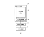
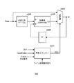
画像表示システム10は、液晶表示装置(広義には、画像表示装置)20と、画像処理装置(表示コントローラー、画像処理コントローラー、画像供給装置)100と、ホスト装置50とを含む。ホスト装置50は、液晶表示装置20に表示する画像データを生成し、画像処理装置100に対して出力する。画像処理装置100は、ホスト装置50からの画像データを圧縮し、圧縮後の画像データを内蔵する画像メモリーにバッファリングする。その後、液晶表示装置20に対して画像データを出力する際に、画像処理装置100は、画像メモリーから読み出した画像データを伸張し、伸張後の画像データを液晶表示装置20に対して出力する。液晶表示装置20は、画像処理装置100からの画像データに基づいて画像の表示を行う。
The
液晶表示装置20は、液晶表示パネル30と、液晶駆動回路40とを含む。液晶表示パネル30は、第1のガラス基板及び第2のガラス基板の間に液晶を封入したものである。第1のガラス基板は例えばアクティブマトリクス基板であり、各画素にアクティブ素子である薄膜トランジスター(Thin Film Transistor:以下、TFT)が設けられている。各画素のTFTのドレイン端子に透明画素電極が、ソース端子にデータ線であるソース線が、ゲート端子に走査線であるゲート線がそれぞれ接続されている。第1のガラス基板と対向する第2のガラス基板には透明電極が設けられている。第2のガラス基板上には、第1のガラス基板の短辺に沿って、液晶表示パネル30を駆動する液晶駆動回路40がCOG(Chip On Glass)実装されている。液晶駆動回路40は、液晶表示パネル30のゲート線に走査信号を、ソース線にデータ信号を供給して液晶表示パネル30を表示駆動する。
The liquid
ホスト装置50は、中央演算処理装置(Central Processing Unit:以下、CPU)及びメモリーを有し、該メモリーに記憶されたプログラムを読み込んだCPUが、該プログラムに対応した処理を実行することで、例えばコンテンツ画像に対応した画像データを生成する。例えばコンテンツ画像としては、動画や静止画、カメラで撮影した自然画、操作に必要なメニュー画面、アイコンなどの文字・図形情報等がある。また、ホスト装置50は、制御データを画像処理装置100が内蔵する制御レジスターに設定することで、画像処理装置100を制御することができる。
The
本実施形態では、上記のように、画像処理装置100が、ホスト装置50からの画像データを圧縮して画像メモリーにバッファリングした後、該画像メモリーから読み出した画像データを伸張して液晶表示装置20に供給する。ここで、画像メモリー内にバッファリングされる画像データの一部を、ホスト装置50が生成した画像データで更新(置換)する場合に、画像処理装置100が、当該領域に対応する画像データを伸張し、更新部分のみ1画素単位で新たな画像データで置き換えて、当該領域の画像データを再び圧縮して画像メモリーに書き戻す。これにより、画像メモリーを有効活用し、且つ使い勝手を向上させた画像処理装置100を提供する。
In the present embodiment, as described above, the
更に、画像処理装置100は、上記の圧縮処理及び伸張処理を、1走査ラインを分割したブロック単位で行う。これにより、圧縮率を低下させることなく、上記のように1画素単位で圧縮した画像データが更新可能な画像処理装置100を提供できるようになる。
Further, the
2. 画像処理装置
2.1 画像処理装置の概要
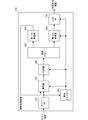
図2に、図1の画像処理装置100の構成例のブロック図を示す。
画像処理装置100は、ホストインターフェース(InterFace:以下、I/Fと略す)110と、選択器120と、LCD(Liquid Crystal Display)I/F130と、制御レジスター150と、圧縮器200と、画像メモリー300と、第1の伸張器400と、第2の伸張器500とを含む。
2. 2. Image Processing Device 2.1 Overview of Image Processing Device FIG. 2 shows a block diagram of a configuration example of the
The
ホストI/F110は、ホスト装置50に接続されたバスを介して入力される画像データ又は制御データに対応する信号の受信インターフェース処理を行う。制御レジスター150には、ホストI/F110を介して受信されたホスト装置50からの制御データが設定される。制御レジスター150に設定された制御データに応じて制御信号が生成され、画像処理装置100の各部は、これらの制御信号に基づいて制御される。
The host I /
選択器120は、ホストI/F110からの入力画像データと、第1の伸張器400からの伸張画像データとのいずれかを圧縮器200に対して出力する。選択器120は、制御レジスター150に設定された制御データに応じて生成された切り換え信号に基づいて切り換え制御を行う。
The
圧縮器200は、選択器120から入力される圧縮処理対象の当該画素の周囲の少なくとも一部の画素の画像データを参照して当該画素の画像データを圧縮する。この圧縮器200は、1走査ラインを分割したブロック(例えば10画素)単位で画像データを圧縮する。そのため、圧縮器200は、当該ブロックの画像データについて圧縮処理を行うと、次のブロックの画像データに対しては改めて圧縮処理を行う。即ち、選択器120から出力された画像データに対して圧縮処理を行う圧縮器200は、ホスト装置50からの画像データをブロック単位で圧縮処理を行う。或いは、圧縮器200は、ホスト装置50からの画像データと第1の伸張器400により伸張された伸張画像データとを1ブロック(広義には圧縮処理単位)内に混在させた画像データをブロック単位で圧縮処理を行う。
The
画像メモリー300は、圧縮器200によって生成された圧縮画像データを記憶する。画像メモリー300は、圧縮処理単位毎に、圧縮画像データの書き込みや読み出しが可能となるように構成される。圧縮器200が、上記のように圧縮処理を行うため、画像メモリー300に格納される画像データのデータサイズを小さくすることができる。
The
第1の伸張器400は、画像メモリー300に記憶された圧縮画像データ(画像データ)を、上記のブロック単位で伸張する。このとき、第1の伸張器400は、ホスト装置50からの更新用の入力画像データの画素位置に対応して画像メモリー300に記憶される圧縮画像データを伸張して伸張画像データを生成する。この伸張画像データが、上記の選択器120に供給される。そして、選択器120は、ホスト装置50からの更新用の入力画像データ又は伸張画像データのいずれかを選択出力し、圧縮器200が、ホスト装置50からの入力画像データにより1画素単位で伸張画像データを更新した更新画像データを圧縮し、圧縮画像データとして画像メモリー300に書き戻す。
The
第2の伸張器500は、画像メモリー300に記憶された圧縮画像データを、上記のブロック単位で伸張する。第2の伸張器500によって伸張された伸張画像データは、LCDI/F130に対して出力される。なお、第2の伸張器500の構成は、第1の伸張器400の構成と同様であってもよいし、異なる構成を有していてもよい。第1の伸張器400及び第2の伸張器500は、圧縮器200において圧縮された画像データを伸張する伸張処理を行うものであればよい。
The
LCDI/F130は、液晶駆動回路40に接続されたバスを介して入出力される信号の送信インターフェース処理を行う。また、LCDI/F120は、液晶表示装置20における表示タイミング制御信号を生成し、画像処理装置100の各部及び液晶表示装置20に対して出力する。この表示タイミング制御信号としては、表示用の垂直同期信号VSYNC、表示用の水平同期信号HSYNC、表示用の画素クロックCLKがあり、LCDI/F130は、上記の表示タイミング制御信号と、該表示タイミング制御信号に同期した送信インターフェース処理後の画像データを液晶表示装置20に対して出力する。
The LCD I /
制御レジスター150は、複数のレジスターを有し、各レジスターには画像処理装置100を制御するための制御データがホストI/F110を介してホスト装置50によって設定される。制御レジスター150の各レジスターに設定された制御データに応じて、画像処理装置100の各部に制御信号が供給される。本実施形態では、この制御レジスター150に、既に画像メモリー300に貯えられている圧縮画像データに対して更新すべき領域に対応する制御データが設定される。そして画像処理装置100では、該制御データに基づいて、上記のように動作する。
The
図3に、本実施形態における圧縮器200における圧縮処理の説明図を模式的に示す。図3において、1走査ラインをn(nは正の整数)画素毎に分割し、各画素の画素値を、「p」に画素番号を付して示している。そして、圧縮処理を関数fで表すものとする。
FIG. 3 schematically shows an explanatory diagram of compression processing in the
圧縮器200は、水平方向に並ぶ複数の画素から構成される1走査ラインをn画素単位で分割したブロック単位で、画像データの差分圧縮を行う。即ち、圧縮器200は、各ブロックの先頭画素についてはそのまま出力し、その後、隣接する画素の画素値との差分を圧縮する。例えば、図3に示すように、第1のブロックBLK1について、先頭画素については、そのまま出力し(p11)、その後、第1のブロックBLK1の最終画素(画素値p1nの画素)まで差分圧縮を行う(f(p12−p11)、・・・、f(p1n−p1(n−1)))。そして、第2のブロックBLK2について、先頭画素については、そのまま出力し(p21)、その後、第2のブロックBLK2の最終画素(画素値p2nの画素)まで差分圧縮を行う(f(p22−p21)、・・・、f(p2n−p2(n−1)))。同様に、第m(mは正の整数)のブロックBLKmについて、先頭画素については、そのまま出力し(pm1)、その後、第mのブロックBLKmの最終画素(画素値pmnの画素)まで差分圧縮を行う(f(pm2−pm1)、・・・、f(pmn−pm(n−1)))。このような差分圧縮を行うことで、画像メモリー300に格納される圧縮画像データのデータサイズを小さくする。
The
なお、第1の伸張器400及び第2の伸張器500も、図3の差分圧縮に対応した差分処理を行う。このようにブロック単位の圧縮処理及び伸張処理は、それぞれの処理において、簡素な構成で、リアルタイムに処理でき、所定以上の圧縮率も確保できる。
Note that the
図4に、図2の選択器120の動作説明図を示す。図4は、既に画像メモリー300に保存されている圧縮画像データを、ホスト装置50からの更新用の入力画像データで部分的に更新する場合のタイミング図の一例を表す。図4において、横軸は時間をとり、縦に第1の伸張器400によって伸張された伸張画像データ、ホストI/F110からの更新用の入力画像データ、選択器120の切り換え信号、選択器120が出力する更新画像データを模式的に表す。
FIG. 4 shows an operation explanatory diagram of the
選択器120は、制御レジスター150に設定された制御データに応じて生成される切り換え信号に基づいて、ホストI/F110からの更新用の入力画像データ、又は第1の伸張器400で伸張された伸張画像データを選択出力する。制御レジスター150に更新領域に対応した制御データが設定されると、画像メモリー300から該更新領域に対応した圧縮画像データがブロック毎に(又は該ブロックを含む走査ライン毎に)読み出され、第1の伸張器400は、伸張処理後の伸張画像データを選択器120に入力する。このとき、更新用の入力画像データの入力タイミングと同期して、伸張画像データが選択器120に入力される。
Based on the switching signal generated according to the control data set in the
そこで、当該ブロックの更新領域の画素のタイミングで、切り換え信号を変化させることで、伸張画像データの一部を、更新用の入力画像データに1画素単位で置換することができる。こうして生成された更新画像データを、選択器120は、圧縮器200に供給し、圧縮器200が、圧縮処理の画像データを画像メモリー300に書き戻す。
Therefore, by changing the switching signal at the timing of the pixel in the update area of the block, a part of the expanded image data can be replaced with the input image data for update in units of one pixel. The
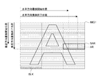
図5に、図2の制御レジスター150に設定される制御データの説明図を示す。図5は、画像メモリー300に既に保存されている圧縮画像データに対応した画像IMG1において、説明の便宜上、1走査ラインが例えば3ブロックで構成されている例を模式的に表すが、本発明は走査ラインのブロック数に限定されるものではない。
FIG. 5 is an explanatory diagram of control data set in the control register 150 of FIG. FIG. 5 schematically shows an example in which one scan line is composed of, for example, three blocks in the image IMG1 corresponding to the compressed image data already stored in the
圧縮器200は、例えば図5のブロックBLK単位で、図3に示す差分圧縮を行う。このとき、例えば、ホスト装置50は、ホストI/F110を介して制御レジスター150を構成する各レジスターに、画像IMG1の水平方向書換開始位置(以下、H書換開始位置)、画像IMG1の水平方向書換終了位置(以下、H書換終了位置)、画像IMG1の垂直方向書換開始位置(以下、V書換開始位置)、及び画像IMG1の垂直方向書換終了位置(以下、V書換終了位置)に対応した制御データを設定する。これらの制御データにより、画像処理装置100では、例えば図5の更新領域ARが特定される。
The
図5のような制御データが制御レジスター150に設定された画像処理装置100は、更新領域ARを含むブロック領域BAR(図5では3ブロック)を特定し、ブロック領域BAR内の圧縮画像データを、ブロック領域BARを含む走査ライン単位(又はブロック領域BARを含む走査ラインのブロック単位)で画像メモリー300から読み出して、第1の伸張器400により伸張処理を行わせる。
The
図6に、図5のブロック領域BARの更新画像データを模式的に示す。図6において、図5と同一部分には同一符号を付し、適宜説明を省略する。 FIG. 6 schematically shows the updated image data of the block area BAR in FIG. In FIG. 6, the same parts as those in FIG.
選択器120には、画像メモリー300から読み出されるブロックの圧縮画像データに対応する更新用の入力画像データと、第1の伸張器400からの伸張画像データとが入力される。そして、選択器120は、更新用の入力画像データと伸張画像データとを図4の切り換え信号により切り換えることで、ブロック毎に、図6に示す構成を有する更新画像データが生成される。圧縮器200は、図6のブロック毎に、差分圧縮処理を行えばよいので、1走査ラインを構成する全画素の画像データに対して再度差分圧縮を行う必要がなく、且つ、1画素単位で、入力画像データに置き換えることが可能となる。
The
以上のような画像処理装置100は、次のように動作する。
The
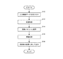
図7に、図2の画像処理装置100の第1の動作例のフローチャートを示す。図7は、ホストI/F110を介してホスト装置50から画像データをそのまま液晶表示装置20に対して供給する通常動作の流れを表す。なお、画像処理装置100が、CPU及びメモリーを有し、該メモリーに格納されたプログラムをCPUが読み出し、CPUがプログラムに対応した処理を実行することで、以下の処理をソフトウェア処理で実現するようにしてもよい。
FIG. 7 shows a flowchart of a first operation example of the
まず、画像処理装置100では、ホストI/F110において、ホスト装置50からの入力画像データを受け付ける(ステップS10)。このとき、選択器120は、ホストI/F110からの入力画像データを圧縮器200に出力するようになっており、圧縮器200が、ステップS10で受け付けられた入力画像データを差分圧縮する(ステップS12)。圧縮器200は、圧縮画像データを画像メモリー300に格納し、画像メモリー300は該圧縮画像データを保存する(ステップS14)。
First, in the
そして、第2の伸張器500が、ステップS14において画像メモリー300に格納された圧縮画像データを読み出し、該圧縮画像データを差分伸張する(ステップS16)。第2の伸張器500によって伸張された伸張画像データはLCDI/F130に出力され、LCDI/F130は、表示タイミング制御信号に同期させて伸張画像データを液晶表示装置20に対して出力し(ステップS18)、一連の処理を終了する(エンド)。
Then, the
図8に、図2の画像処理装置100の第2の動作例のフローチャートを示す。図8は、ホストI/F110を介してホスト装置50から画像データを画像メモリー300にバッファリングし、画像メモリー300内の圧縮画像データの一部を更新してから液晶表示装置20に対して供給する更新動作の流れを表す。なお、画像処理装置100が、CPU及びメモリーを有し、該メモリーに格納されたプログラムをCPUが読み出し、CPUがプログラムに対応した処理を実行することで、以下の処理をソフトウェア処理で実現するようにしてもよい。
FIG. 8 shows a flowchart of a second operation example of the
まず、画像処理装置100では、ホストI/F110において、ホスト装置50からの入力画像データを受け付ける(ステップS20)。このとき、選択器120は、ホストI/F110からの入力画像データを圧縮器200に出力するようになっており、圧縮器200が、ステップS10で受け付けられた入力画像データを上記のように差分圧縮する(ステップS22、第1の圧縮ステップ)。圧縮器200は、圧縮画像データを画像メモリー300に格納し、画像メモリー300は該圧縮画像データを保存する(ステップS24)。
First, in the
次に、ホスト装置50は、ステップS24で保存された圧縮画像データの更新領域に対応した制御データを制御レジスター150に設定し、画像処理装置100は、ホストI/F110を介してホスト装置50から入力される更新用の入力画像データを受け付ける(ステップS26)。
Next, the
ここで、第1の伸張器400は、ステップS26の更新用の入力画像データに対応して画像メモリー300に記憶される圧縮画像データを、更新領域のブロックを含む走査ライン分(又は更新領域の1ブロック分)だけ読み出し、該圧縮画像データを差分伸張する(ステップS28、第1の伸張ステップ)。なお、ステップS28では、画像メモリー300から読み出される圧縮画像データは、制御レジスター150に設定された更新領域に対応する圧縮画像データである。第1の伸張器400によって伸張された伸張画像データは、選択器120に供給される。
Here, the
選択器120は、制御レジスター150に設定された制御データに対応して生成された切り換え信号により、ホストI/F110からの更新用の入力画像データ又は第1の伸張器400からの伸張画像データを切り換えて、1ブロック内で、更新用の入力画像データ及び伸張画像データが混在した更新画像データを生成する(ステップS30)。この更新画像データは、圧縮器200に入力され、圧縮器200は、ステップS30で生成された更新画像データを差分圧縮する(ステップS32、第2の圧縮ステップ)。圧縮器200は、圧縮画像データを画像メモリー300に格納し、画像メモリー300は該圧縮画像データを保存する(ステップS34)。
The
そして、第2の伸張器500が、ステップS34において画像メモリー300に格納された圧縮画像データを読み出し、該圧縮画像データを差分伸張する(ステップS36、第2の伸張ステップ)。第2の伸張器500によって差分伸張された伸張画像データはLCDI/F130に出力され、LCDI/F130は、表示タイミング制御信号に同期させて伸張画像データを液晶表示装置20に対して出力し(ステップS38)、一連の処理を終了する(エンド)。
Then, the
以上のように、第1の圧縮ステップでは、当該画素の周囲の少なくとも一部の画素の画像データを参照して前記当該画素の画像データを圧縮して圧縮画像データを生成し、該圧縮画像データを画像メモリー300に格納する。その後、第1の伸張ステップでは、入力画像データに対応して前記メモリーに記憶される圧縮画像データを伸張して伸張画像データを生成する。更に再び、第2の圧縮ステップでは、入力画像データにより伸張画像データを更新した更新画像データを圧縮し、圧縮画像データとして画像メモリー300に書き戻す。
As described above, in the first compression step, the compressed image data is generated by compressing the image data of the pixel with reference to the image data of at least some pixels around the pixel, and the compressed image data. Is stored in the
このように、画像メモリー300に既に記憶されている圧縮画像データのうち、当該領域の圧縮画像データのみを読み出して伸張し、更新用の入力画像データに対して更新すべき領域のみを置き換えるようにしたので、パーシャル圧縮動作の処理単位である1ブロックを構成する画素数を多くして、圧縮率を向上させることができるようになる。そして、1ブロックを構成する画素数を多くしても、画像メモリー300に記憶される圧縮画像データを1画素単位で書き換えることができるようになる。
As described above, among the compressed image data already stored in the
2.2 画像処理装置の詳細な構成例
次に、本実施形態における画像処理装置100の詳細な構成例について説明する。以下では、画像処理装置100の構成例について、圧縮器200による圧縮処理側と第1の伸張器400による伸張処理側とに着目して説明する。
2.2 Detailed Configuration Example of Image Processing Device Next, a detailed configuration example of the
図9に、画像処理装置100の詳細な構成例のブロック図を示す。図9は、圧縮器200による圧縮処理を実現する構成を表す。図9において、図2と同一部分には同一符号を付し、適宜説明を省略する。
FIG. 9 is a block diagram illustrating a detailed configuration example of the
画像処理装置100は、Hカウンター210、Vカウンター220、アドレス計算回路230、メモリーライト回路240、部分書換有効信号生成回路242を含む。図9では、制御レジスター150に、図5で説明したH書換開始位置、H書換終了位置、V書換開始位置、及びV書換終了位置に対応した制御データの他に、部分書換イネーブルに対応した制御データが設定される。この部分書換イネーブル状態が指定されるレジスターに、イネーブルに対応した制御データが設定されると、圧縮画像データの一部の更新処理が行われる。
The
Hカウンター210は、フレーム先頭信号によりリセットされ、画素クロックCLKに同期して、画像の水平方向の画素数をカウントするカウンターであり、H書換開始位置、及びH書換終了位置の各々に対応する制御データが入力される。Hカウンター210は、カウントを開始すると、ライン先頭識別信号を出力すると共に、H書換開始位置からH書換終了位置に対応するカウント値までアクティブとなる水平書換有効信号を出力する。
The
Vカウンター220は、フレーム先頭信号によりリセットされ、ライン先頭識別信号に同期して、画像の垂直方向のライン数をカウントするカウンターであり、V書換開始位置、及びV書換終了位置の各々に対応する制御データが入力される。Vカウンター220は、カウントを開始すると、(V書換終了位置−V書換開始位置)に対応するカウント値になったときに、1フレーム終了信号をパルス出力すると同時に、Vカウンター220のカウント値を「0」に初期化する。 The V counter 220 is a counter that is reset by the frame head signal and counts the number of lines in the vertical direction of the image in synchronization with the line head identification signal, and corresponds to each of the V rewrite start position and the V rewrite end position. Control data is input. When the count starts, when the count value corresponding to (V rewrite end position−V rewrite start position) is reached, the V counter 220 outputs a 1-frame end signal as a pulse, and simultaneously the count value of the V counter 220 is changed to “ It is initialized to “0”.
部分書換イネーブルに設定されているときライン先頭識別信号が入力されると、アドレス計算回路230は、H書換開始位置及びV書換開始位置に基づいて、画像メモリー300における当該走査ラインの圧縮画像データの記憶位置に対応するライン先頭アドレスを生成する。
When the line head identification signal is input when the partial rewrite enable is set, the
メモリーライト回路240は、圧縮器200によって圧縮された画像データを画像メモリー300に格納する制御を行う。より具体的には、メモリーライト回路240は、Vカウンター220からの1フレーム終了信号により初期化され、アドレス計算回路230により生成されたライン先頭アドレスに基づいて、ライト信号WRに同期して、画像メモリー300に対してアドレス信号Add及び画像データDataを出力する。なお、メモリーライト回路240が1フレーム終了信号により初期化されるのではなく、ホストI/F110からのフレーム先頭信号により初期化されるように構成されてもよい。
The
部分書換有効信号生成回路242は、Hカウンター210により生成された水平書換有効信号及び部分書換イネーブル状態に基づいて部分書換有効信号(選択器120の切り換え信号)を生成する。より具体的には、部分書換有効信号生成回路242は、水平書換有効信号と部分書換イネーブルとの論理積演算結果を部分書換有効信号として出力することができる。
The partial rewrite valid
この部分書換有効信号が切り換え信号として供給される選択器120は、第1のセレクターと、第2のセレクターとを有する。第1のセレクターは、ホストI/F110から入力画像データと第1の伸張器400からの伸張画像データのいずれかを部分書換有効信号に基づいて切り換えて出力する。第2のセレクターは、ホストI/F110からデータイネーブル信号と第1の伸張器400からのデータイネーブル信号のいずれかを部分書換有効信号に基づいて切り換えて出力する。
The
選択器120が、部分書換有効信号によりホストI/F110からの入力画像データを出力する場合、ホストI/F110からのデータイネーブル信号DataEnableがアクティブになって画像の水平方向の画像データが有効になると、Hカウンター210は、ライン先頭識別信号を1パルス分だけアクティブにする。そして、圧縮器200は、図3で説明したように差分圧縮処理を行う。より具体的には、圧縮器200は、ライン先頭識別信号に対応する走査ラインを分割する各ブロックの先頭画素については、そのまま出力し、その後、差分圧縮を行う。
When the
一方、選択器120が、部分書換有効信号によりホストI/F110からの入力画像データと第1の伸張器400からの伸張画像データとを切り換えて更新画像データを生成する場合、ホストI/F110又は第1の伸張器400からのデータイネーブル信号DataEnableがアクティブとなって画像データが有効になると、圧縮器200は、同様に、更新画像データに対して、図3で説明したように差分圧縮処理を行う。
On the other hand, when the
このような圧縮処理を行う圧縮器200は、例えば次のような構成により実現できる。
The
図10に、図9の圧縮器200の構成例のブロック図を示す。図10において、図2と同一部分には同一符号を付し、適宜説明を省略する。
FIG. 10 shows a block diagram of a configuration example of the
圧縮器200は、1画素を構成するR成分、G成分及びB成分のサブ画素毎に画像データの圧縮処理(符号化)を行う。図10では、圧縮器200のうち、R成分のサブ画素の画像データに対して圧縮処理を行う構成を示すが、圧縮器200においてG成分及びB成分のサブ画素についても同様に構成される。
The
圧縮器200のうちR成分の画像データに対して符号化を行う部分は、減算器250R、量子化テーブル252R、逆量子化テーブル254R、加算器256R、選択器258R、260R、フリップフロップ262R、画素カウンター264Rを含む。
The portion of the
減算器250Rは、入力された画像データと、フリップフロップ262Rに保持された直前の隣接画素の画像データとの差分を求め、キャリービット(ボロービット)を含む差分データを出力する。この差分データは、量子化テーブル252Rに供給される。量子化テーブル252Rには、予め入力値に対応して該入力値を量子化した出力値が登録されており、差分データを入力値として、出力値である量子化データを出力する。量子化データは、逆量子化テーブル254Rに供給される。
The
逆量子化テーブル254Rは、量子化テーブル252Rに対応するテーブルであり、予め入力値に対応して該入力値を逆量子化して量子化テーブル252Rの入力値となるような出力値が登録されている。逆量子化テーブル254Rは、量子化テーブル252Rからの量子化データを入力値として、出力値である逆量子化データを出力する。 The inverse quantization table 254R is a table corresponding to the quantization table 252R, and an output value is registered in advance such that the input value corresponding to the input value is inversely quantized to become the input value of the quantization table 252R. Yes. The inverse quantization table 254R receives the quantized data from the quantization table 252R as an input value and outputs inverse quantized data that is an output value.
量子化テーブル252Rからの量子化データは、選択器258Rにも入力される。選択器258Rには、量子化データと、オリジナルの画像データとが入力され、画素カウンター264Rによって生成される選択制御信号SELに基づいて、いずれか1つのデータを出力する。選択器258Rの出力データが、符号化データとして画像メモリー300に格納される。
The quantized data from the quantization table 252R is also input to the
逆量子化テーブル254Rからの逆量子化データは、加算器256Rに入力される。加算器256Rには、逆量子化データとフリップフロップ262Rに保持された画像データとが入力される。加算器256Rは、逆量子化データとフリップフロップ262Rの画像データとを加算し、加算データを選択器260Rに供給する。選択器260Rには、加算器256Rからの加算データと、オリジナルの画像データとが入力され、画素カウンター264Rによって生成される選択制御信号SELに基づいて、いずれか1つのデータを出力する。選択器260Rの選択データは、フリップフロップ262Rにおいて保持される。フリップフロップ262Rは、ホストI/F110を介して入力される画像データに対応した画素クロックCLKを用いて、選択データをラッチできる。
The inversely quantized data from the inverse quantization table 254R is input to the
画素カウンター264Rには、画素クロックCLK、データイネーブル信号DataEnable、フレーム先頭信号、及びライン先頭識別信号が入力され、1走査ラインを分割したブロック単位で符号化が行われるように選択制御信号SELを生成する。画素カウンター264Rは、フレーム先頭信号又はライン先頭識別信号によりリセットされ、データイネーブル信号DataEnableがアクティブの期間は画素クロックCLKによりカウントアップされるカウンターを有する。
A pixel clock CLK, a data enable signal DataEnable, a frame head signal, and a line head identification signal are input to the
図11に、図10に示す圧縮器200の動作例を模式的に示す。図11は、横軸に時間軸をとり、圧縮器200に入力される圧縮前の画像データ、選択制御信号SEL、及び圧縮画像データを表す。
FIG. 11 schematically shows an operation example of the
圧縮器200は、図10に示す構成が色成分毎に並列に設けられており、色成分毎に、並列に各色成分の差分圧縮を行う。各色成分の画素カウンターは、フレーム先頭信号又はライン先頭識別信号によりリセットされ、データイネーブル信号DataEnableがアクティブの期間にカウント動作を行い、1走査ラインを構成するブロック単位の先頭画素の圧縮処理期間にアクティブとなり、それ以外の画素の圧縮処理期間に非アクティブとなるように選択制御信号SELを生成する。これにより、選択器258Rが選択出力するデータが切り換えられ、その結果、ブロック毎に、先頭画素については圧縮処理を行うことなくそのまま出力し(図11の未符号化期間)、先頭画素に続く画素について符号化処理後のデータが出力される(図11の符号化期間)。
The
図12に、画像処理装置100の詳細な構成例のブロック図を示す。図12は、第1の伸張器400による伸張処理を実現する構成を表す。図12において、図2と同一部分には同一符号を付し、適宜説明を省略する。
FIG. 12 shows a block diagram of a detailed configuration example of the
画像処理装置100は、Hカウンター410、Vカウンター420、アドレス計算回路430、メモリーリード回路440を含む。
The
Hカウンター410は、フレーム先頭信号によりリセットされ、画素クロックCLKに同期して、画像の水平方向の画素数をカウントするカウンターであり、H書換ケア開始位置、及びH書換終了位置の各々に対応する制御データが入力される。Hカウンター410は、カウントを開始すると、ライン先頭識別信号を出力する。
The
Vカウンター420は、フレーム先頭信号によりリセットされ、ライン先頭識別信号に同期して、画像の垂直方向のライン数をカウントするカウンターであり、V書換開始位置、及びV書換終了位置の各々に対応する制御データが入力される。Vカウンター420は、カウントを開始すると、(V書換終了位置−V書換開始位置)に対応するカウント値になったときに、1フレーム終了信号をパルス出力すると同時に、Vカウンター220のカウント値を「0」に初期化する。
The
アドレス計算回路430は、ライン先頭識別信号が入力されると、H書換開始位置及びV書換開始位置に基づいて、画像メモリー300における当該走査ラインの圧縮画像データの記憶位置に対応するライン先頭アドレスを生成する。
When the line head identification signal is input, the
メモリーリード回路440は、画像メモリー300に格納された圧縮画像データを読み出す制御を行う。より具体的には、メモリーリード回路440は、Vカウンター420からの1フレーム終了信号がアクティブになるまで、リード信号RDに同期して、画像メモリー300に対してアドレス信号Addを出力することで、圧縮画像データDataを読み出す。
The memory read
第1の伸張器400は、データイネーブル信号DataEnableがアクティブとなって画像データが有効になると、アドレス計算回路430によって生成されたライン先頭アドレスに対応して画像メモリー300に記憶された当該ブロックの圧縮画像データに対して、図3で説明した差分圧縮処理に対応した差分伸張処理を行う。
When the data enable signal DataEnable becomes active and the image data becomes valid, the
このような伸張処理を行う第1の伸張器400は、例えば次のような構成により実現できる。
The
図13に、図12の第1の伸張器400の構成例のブロック図を示す。図13において、図2と同一部分には同一符号を付し、適宜説明を省略する。
FIG. 13 shows a block diagram of a configuration example of the
第1の伸張器400は、1画素を構成するR成分、G成分及びB成分のサブ画素毎に画像データの伸張処理(復号化)を行う。図13では、第1の伸張器400のうち、R成分のサブ画素の画像データに対して伸張処理を行う構成を示すが、第1の伸張器400において、G成分及びB成分のサブ画素についても同様に構成される。
The
第1の伸張器400のうちR成分の画像データに対して復号化を行う部分は、逆量子化テーブル450R、加算器452R、選択器456R、フリップフロップ458R、画素カウンター460Rを含む。
The portion of the
逆量子化テーブル450Rは、図10の逆量子化テーブル254Rと同様であり、逆量子化テーブル450Rは、符号化データを逆量子化データに変換する。加算器452Rには、逆量子化テーブル450Rからの逆量子化データとフリップフロップ458Rに保持された画像データとが入力される。加算器452Rは、逆量子化データとフリップフロップ458Rの画像データとを加算し、加算データとして出力する。加算データは、選択器456Rに入力される。選択器456Rには、オリジナルの画像データ(画像メモリー300から読み出された画像データ)と、加算データとが入力され、画素カウンター460Rにより生成された選択制御信号SEL1に基づいていずれか1つのデータが出力される。選択器456Rの選択データは、フリップフロップ458Rにおいて保持される。フリップフロップ458Rは、ホストI/F110を介して入力される画像データに対応した画素クロックCLKを用いて、選択データをラッチできる。
The inverse quantization table 450R is the same as the inverse quantization table 254R in FIG. 10, and the inverse quantization table 450R converts encoded data into inversely quantized data. The
画素カウンター460Rには、画素クロックCLK、データイネーブル信号DataEnable、フレーム先頭信号、ライン先頭識別信号が入力され、1走査ラインを分割したブロック単位で復号化が行われるように選択制御信号SEL1を生成する。画素カウンター460Rは、フレーム先頭信号又はライン先頭識別信号によりリセットされ、データイネーブル信号DataEnableがアクティブの期間は画素クロックCLKによりカウントアップされるカウンターを有する。
The
第1の伸張器400は、図13に示す構成が色成分毎に並列に設けられており、色成分毎に、並列に各色成分の差分伸張を行う。各色成分の画素カウンターは、フレーム先頭信号又はライン先頭識別信号によりリセットされ、データイネーブル信号DataEnableがアクティブの期間にカウント動作を行い、1走査ラインを構成するブロック単位の先頭画素の伸張処理期間にアクティブとなり、それ以外の画素の伸張処理期間に非アクティブとなるように選択制御信号SEL1を生成する。これにより、選択器456Rが選択出力するデータが切り換えられ、その結果、ブロック毎に、先頭画素については伸張処理を行うことなくそのまま出力し、先頭画素に続く画素について復号化処理後のデータが出力される。
The
以上説明したように、本実施形態では、画像処理装置100において、1走査ラインを分割したブロック単位で圧縮器200により画像データを圧縮して画像メモリー300にバッファリングする場合であっても、1画素単位で更新用の入力画像データと切り換えて生成した更新画像データを圧縮して画像メモリー300に書き戻すようにしたので、圧縮率を低下させることなく、使い勝手を向上させた画像処理装置を提供できるようになる。
As described above, in the present embodiment, even when the
3. 変形例
3.1 第1の変形例
上記の実施形態では、1走査ラインを分割したブロック単位で、画像データの圧縮処理及び伸張処理を行うものとして説明したが、本発明はこれに限定されるものではない。本実施形態の第1の変形例では、圧縮器200が1走査ライン単位で画像データを圧縮すると共に、第1の伸張器400が、1走査ライン単位で画像データを伸張する。この場合でも、本実施形態と比べて、画像メモリーを有効活用し、且つ使い勝手を向上させる一方で、圧縮率をより一層向上させることができるようになる。
3. Modified Example 3.1 First Modified Example In the above embodiment, image data compression processing and decompression processing have been described in units of blocks obtained by dividing one scanning line. However, the present invention is limited to this. It is not a thing. In the first modification of the present embodiment, the
図14に、本実施形態の第1の変形例における圧縮器の圧縮処理の説明図を示す。図14において、1走査ラインの水平方向の画素数がN(Nは正の整数、以下同様)であり、各画素の画素値を、「p」に画素番号を付して示している。そして、圧縮処理を関数fで表すものとする。 FIG. 14 is an explanatory diagram of compression processing of the compressor in the first modification of the present embodiment. In FIG. 14, the number of pixels in the horizontal direction of one scanning line is N (N is a positive integer, the same applies hereinafter), and the pixel value of each pixel is indicated by attaching a pixel number to “p”. The compression process is represented by a function f.
データイネーブル信号DataEnableがアクティブになって画像の水平方向の画像データが有効になると、第1の変形例におけるHカウンターは、ライン先頭識別信号を1パルス分だけアクティブにする。そして、図14に示すように、ライン先頭識別信号に対応する走査ラインの先頭画素については、そのまま出力し(p1)、その後、差分圧縮を行う(f(p2−p1)、f(p3−p2)、・・・、f(pN−1−pN−2)、f(pN−pN−1))。これにより、画像メモリー300格納される圧縮画像データのデータサイズを小さくする。
When the data enable signal DataEnable becomes active and the image data in the horizontal direction of the image becomes valid, the H counter in the first modification activates the line head identification signal for one pulse. Then, as shown in FIG. 14, the head pixel of the scanning line corresponding to the line head identification signal is output as it is (p 1 ), and then differential compression is performed (f (p 2 −p 1 ), f ( p 3 -p 2), ···, f (p N-1 -p N-2), f (p N -p N-1)). Thereby, the data size of the compressed image data stored in the
第1の変形例において、第1の伸張器及び第2の伸張器は、図14に示す圧縮器における圧縮処理に対応した伸張処理を行う。このような第1の変形例では、1走査ライン単位で画像データを圧縮するため、画素値をそのまま出力する先頭画素数が減少し、本実施形態と比較して、1処理単位の圧縮処理時間がかかるものの、圧縮率を向上させることができるようになる。なお、第1の変形例においても、本実施形態と同様に、1画素単位で、画像データを書き換えることは可能である。 In the first modification, the first decompressor and the second decompressor perform decompression processing corresponding to the compression processing in the compressor shown in FIG. In such a first modification, since the image data is compressed in units of one scanning line, the number of head pixels for outputting the pixel values as they are is reduced, and the compression processing time in one processing unit as compared with the present embodiment. However, the compression rate can be improved. Note that in the first modification as well, the image data can be rewritten in units of one pixel as in the present embodiment.
3.2 第2の変形例
本実施形態又はその第1の変形例では、画像メモリーに記憶される圧縮画像データを、第1の伸張器とは別に設けられた第2の伸張器により伸張して、LCDI/Fを介して液晶表示装置に出力するものとして説明したが、本発明はこれに限定されるものではない。本実施形態の第2の変形例では、第1の伸張器により伸張された伸張画像データを、LCDI/Fにも出力し、画像処理装置が第2の伸張器を省略した構成を有している。
3.2 Second Modification In this embodiment or a first modification thereof, compressed image data stored in an image memory is decompressed by a second decompressor provided separately from the first decompressor. In the above description, output to the liquid crystal display device via the LCD I / F has been described, but the present invention is not limited to this. In the second modification of the present embodiment, the decompressed image data decompressed by the first decompressor is also output to the LCD I / F, and the image processing apparatus has a configuration in which the second decompressor is omitted. Yes.
図15に、本実施形態の第2の変形例における画像処理装置の構成例のブロック図を示す。図15において、図2と同一部分には同一符号を付し、適宜説明を省略する。 FIG. 15 is a block diagram showing a configuration example of the image processing apparatus according to the second modification of the present embodiment. In FIG. 15, the same parts as those in FIG.
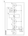
画像処理装置600は、ホストI/F110と、選択器120、LCDI/F130と、制御レジスター150と、圧縮器200と、画像メモリー300と、第1の伸張器400と、ラインメモリー610とを含む。即ち、第2の変形例における画像処理装置600が本実施形態における画像処理装置100と異なる点は、第2の伸張器500が省略され、ラインメモリー610が追加されている点である。
The
ラインメモリー610は、第1の伸張器400によって伸張された更新領域の少なくとも1走査ライン分の伸張画像データ(又は1走査ラインを分割した1ブロック分の伸張画像データ)を保持する。ラインメモリー610に保持された伸張画像データは、選択器120に供給される。そして、第1の伸張器400に伸張された伸張画像データは、LCDI/F130を介して液晶表示装置20に対して出力される。
The
即ち、選択器120は、本実施形態と同様に、伸張画像データと更新用の入力画像データのいずれかを選択出力して更新画像データを出力するが、この伸張画像データがラインメモリー610に蓄積されたものである。そして、第1の伸張器400が、部分更新される領域の圧縮画像データの伸張処理に加えて、画像メモリー300に記憶された1画面分の圧縮画像データの伸張処理も行う。従って、第1の伸張器400によって伸張された画像データを、液晶表示装置20に供給することができる。
That is, as in the present embodiment, the
このような第2の変形例によれば、伸張器を1つ備えるだけで済むため、画像処理装置600の構成を簡素化でき、回路規模を縮小することができる。但し、第1の伸張器400が2つの伸張処理を行う必要があるため、伸張処理の切り換え制御が必要となる。
According to the second modified example, since only one decompressor is required, the configuration of the
従って、第2の変形例における画像処理装置は、第1の伸張器400によって伸張された画像データを液晶表示装置20に供給することができるように構成される。
Therefore, the image processing apparatus according to the second modification is configured so that the image data expanded by the
以上のような第1の変形例又は第2の変形例における画像処理装置は、図1の画像表示システムにおける画像処理装置に置き換えることが可能である。従って、第1の変形例又は第2の変形例における画像処理装置を含む画像表示システムによれば、本実施形態と同様の効果を得ることができる。 The image processing apparatus in the first modification or the second modification as described above can be replaced with the image processing apparatus in the image display system of FIG. Therefore, according to the image display system including the image processing apparatus in the first modification example or the second modification example, the same effect as in the present embodiment can be obtained.
4. 電子機器
本実施形態における画像処理装置100又はその変形例における画像処理装置、又は上記のいずれかの画像処理装置を含む画像表示システムは、例えば次のような電子機器に適用することができる。以下では、本実施形態における画像処理装置100又はこれを含む画像表示システム10が適用される例について説明するが、第1の変形例又は第2の変形例における画像処理装置又はこれを含む画像表示システムも同様に適用できる。
4). Electronic Device The
図16に、本実施形態における電子機器としての携帯電話機の構成例のブロック図を示す。図16において、図1と同一部分には同一符号を付し、適宜説明を省略する。 FIG. 16 shows a block diagram of a configuration example of a mobile phone as an electronic apparatus in the present embodiment. In FIG. 16, the same parts as those in FIG.
携帯電話機900は、カメラモジュール910を含む。カメラモジュール910は、CCDカメラを含み、CCDカメラで撮像した画像のデータを画像処理装置100に供給する。
The
また、携帯電話機900は、液晶表示パネル30を含む。液晶表示パネル30は、液晶駆動回路40によって駆動される。液晶表示パネル30は、複数のゲート線、複数のソース線、複数の画素を含む。液晶駆動回路40は、ゲートドライバ42、ソースドライバ44及び電源回路46を含む。ゲートドライバ42は、液晶表示パネル30の複数のゲート線を走査する。ソースドライバ44は、液晶表示パネル30の複数のソース線を、画像データに基づいて駆動する。電源回路46は、ゲートドライバ42、ソースドライバ44及び液晶表示パネル30の電圧を生成する。電源回路46は、ソースドライバ44及びゲートドライバ42に接続され、各ドライバに対して、駆動用の電源電圧を供給する。また電源回路46は、液晶表示パネル30の対向電極に、対向電極電圧Vcomを供給する。
In addition, the
画像処理装置100は、液晶駆動回路40に接続され、ソースドライバ44に対して上記の合成処理が行われたRGBフォーマットの画像データを供給する。
The
ホスト装置50は、画像処理装置100に接続され、画像データを画像処理装置100に供給すると共に、画像処理装置100を制御する。またホスト装置50は、アンテナ960を介して受信された画像データを、変復調部950で復調した後、画像処理装置100に供給できる。画像処理装置100は、この画像データに基づき、ソースドライバ44及びゲートドライバ42により液晶表示パネル30に表示させる。また、ホスト装置50は、カメラモジュール910で生成された画像データを変復調部950で変調した後、アンテナ960を介して他の通信装置への送信を指示できる。更に、ホスト装置50は、操作入力部970からの操作情報に基づいて画像データの送受信処理、カメラモジュール910の撮像、液晶表示パネル30の表示処理を行う。
The
図17(A)、図17(B)に、本実施形態における画像処理装置100又は画像表示システム10が適用された電子機器の構成を示す斜視図を示す。図17(A)は、図16の携帯電話機の構成の斜視図を表す。図17(B)は、モバイル型のパーソナルコンピューターの構成の斜視図を表す。図17(A)において、図16と同一部分には同一符号を付し、適宜説明を省略する。
17A and 17B are perspective views showing the configuration of an electronic apparatus to which the
図17(A)に示す携帯電話機900は、本体部980と、表示部990とを含む。表示部990として、本実施形態における画像表示システム10の液晶表示パネル30が実装される。本体部980は、画像表示システム10のうちホスト装置50を含み、この本体部980には操作入力部970としてキーボードが設けられる。即ち、携帯電話機900は、少なくとも上記の実施形態における画像処理装置100を含んで構成される。キーボードを介した操作情報がホスト装置50によって解析され、その操作情報に応じて表示部990に画像が表示される。本実施形態によれば、圧縮画像データを記憶する画像メモリーの一部のみを1画素単位で更新できる上に、圧縮率を向上させることができるため、より多くの画像や情報を蓄積でき、より多機能な携帯電話機を低コストで提供できるようになる。
A
図17(B)に示すパーソナルコンピューター1000は、本体部1010と、表示部1020とを含む。表示部1020として、本実施形態における画像表示システム10の液晶表示パネル30が実装される。本体部1010は、画像表示システム10のうちホスト装置50を含み、この本体部1010にはキーボード1030が設けられる。即ち、パーソナルコンピューター1000は、少なくとも上記の実施形態における画像処理装置100を含んで構成される。キーボード1030を介した操作情報がホスト装置50によって解析され、その操作情報に応じて表示部1020に画像が表示される。本実施形態によれば、圧縮画像データを記憶する画像メモリーの一部のみを1画素単位で更新できる上に、圧縮率を向上させることができるため、より多くの画像や情報を蓄積でき、より多機能なパーソナルコンピューターを低コストで提供できるようになる。
A
なお、本実施形態における画像処理装置100又は画像表示システム10(第1の変形例又は第2の変形例における画像処理装置又はこれを含む画像表示システム)が適用された電子機器として、図17(A)、図17(B)に示すものに限定されるものではなく、情報携帯端末(PDA:Personal Digital Assistants)、デジタルスチルカメラ、テレビ、ビデオカメラ、カーナビゲーション装置、ページャー、電子手帳、電子ペーパー、電卓、ワードプロセッサー、ワークステーション、テレビ電話、POS(Point of sale system)端末、プリンター、スキャナー、複写機、ビデオプレーヤー、タッチパネルを備えた機器等が挙げられる。
Note that an electronic apparatus to which the
以上、本発明に係る画像処理装置、画像表示システム、電子機器及び画像処理方法等を上記の実施形態又はその変形例に基づいて説明したが、本発明は上記の実施形態又はその変形例に限定されるものではなく、その要旨を逸脱しない範囲において種々の態様において実施することが可能であり、例えば次のような変形も可能である。 As described above, the image processing apparatus, the image display system, the electronic device, the image processing method, and the like according to the present invention have been described based on the above-described embodiment or its modification. However, the present invention is limited to the above-described embodiment or its modification. However, the present invention can be implemented in various modes without departing from the gist of the invention. For example, the following modifications are possible.
(1)上記の実施形態又はその変形例では、液晶表示装置に画像データを供給する画像処理装置を例に説明したが、本発明はこれに限定されるものではない。本実施形態における画像処理装置が、有機EL表示装置やCRT(Cathode-Ray Tube)等の表示装置や画像投影装置に画像データを供給するようにしてもよい。 (1) In the above embodiment or its modification, the image processing apparatus that supplies image data to the liquid crystal display device has been described as an example, but the present invention is not limited to this. The image processing apparatus according to the present embodiment may supply image data to a display apparatus such as an organic EL display apparatus or a CRT (Cathode-Ray Tube) or an image projection apparatus.
(2)上記の実施形態又はその変形例では、圧縮器及び第1の伸張器が、差分圧縮及びこれに対応する差分伸張処理を行う例について説明したが、本発明は、圧縮処理の処理内容及び伸張処理の処理内容に限定されるものではない。 (2) In the above-described embodiment or its modification, the example in which the compressor and the first decompressor perform differential compression and differential decompression processing corresponding thereto has been described. In addition, the processing contents of the decompression process are not limited.
(3)上記の実施形態又はその変形例では、圧縮処理が、1走査ライン単位、又は1走査ラインを分割したブロック単位で行われ、該圧縮処理に対応した伸張処理も同様であるものとして説明したが、本発明はこれに限定されるものではない。例えば、圧縮処理が、1走査ライン単位又はブロック単位で行われなくてもよい。 (3) In the above embodiment or its modification, it is assumed that the compression processing is performed in units of one scanning line or in units of blocks obtained by dividing one scanning line, and the decompression processing corresponding to the compression processing is the same. However, the present invention is not limited to this. For example, the compression process may not be performed in units of one scanning line or blocks.
(4)上記の実施形態又はその変形例において、圧縮器の構成が図10に示す構成であるものとして説明したが、本発明はこれに限定されるものではない。 (4) In the above embodiment or its modification, the compressor has been described as having the configuration shown in FIG. 10, but the present invention is not limited to this.
(5)上記の実施形態又はその変形例において、第1の伸張器の構成が図13に示す構成であるものとして説明したが、本発明はこれに限定されるものではない。 (5) In the above-described embodiment or its modification, the first decompressor has been described as having the configuration shown in FIG. 13, but the present invention is not limited to this.
(6)上記の実施形態又はその変形例において、第2の伸張器の構成に限定されるものではない。また、第1の伸張器と第2の伸張器とが互いに異なるアルゴリズムで圧縮画像データを伸張してもよい。 (6) In the above-described embodiment or its modification, it is not limited to the configuration of the second expander. Further, the first decompressor and the second decompressor may decompress the compressed image data using different algorithms.
(7)上の実施形態又はその変形例において、画像処理装置が、圧縮器、第1の伸張器及び第2の伸張器を備える構成を有するものとして説明したが、本発明はこれに限定されるものではない。例えば、圧縮器が行う圧縮処理を、ソフトウェア処理で実現するようにしてもよい。また、第1の伸張器が行う伸張処理を、ソフトウェア処理で実現するようにしてもよい。同様に、第2の伸張器が行う伸張処理を、ソフトウェア処理で実現するようにしてもよい。 (7) In the above embodiment or its modification, the image processing apparatus has been described as having a configuration including a compressor, a first expander, and a second expander. However, the present invention is not limited to this. It is not something. For example, the compression processing performed by the compressor may be realized by software processing. Further, the decompression process performed by the first decompressor may be realized by software processing. Similarly, the decompression process performed by the second decompressor may be realized by software processing.
(8)上記の実施形態又はその変形例において、本発明を、画像処理装置、画像表示システム、電子機器及び画像処理方法等として説明したが、本発明はこれに限定されるものではない。例えば、上記の画像処理方法の処理手順が記述されたプログラムや、該プログラムが記録された記録媒体であってもよい。 (8) Although the present invention has been described as an image processing apparatus, an image display system, an electronic apparatus, an image processing method, and the like in the above-described embodiment or its modification, the present invention is not limited to this. For example, it may be a program in which the processing procedure of the image processing method is described, or a recording medium on which the program is recorded.
10…画像表示システム、 20…液晶表示装置、 30…液晶表示パネル、
40…液晶駆動回路、 50…ホスト装置、 100,600…画像処理装置、
110…ホストI/F、 120…選択器、 130…LCDI/F、
150…制御レジスター、 200…圧縮器、 210,410…Hカウンター、
220,420…Vカウンター、 230,430…アドレス計算回路、
240…メモリーライト回路、 300…画像メモリー、 400…第1の伸張器、
440…メモリーリード回路、 500…第2の伸張器、 610…ラインメモリー、
900…携帯電話機、 910…カメラモジュール、 950…変復調部、
960…アンテナ、 970…操作入力部、 980,1010…本体部、
990,1020…表示部、 1000…パーソナルコンピューター、
1030…キーボード
DESCRIPTION OF
40 ... Liquid crystal drive circuit, 50 ... Host device, 100, 600 ... Image processing device,
110 ... Host I / F, 120 ... Selector, 130 ... LCD I / F,
150 ...
220, 420 ... V counter, 230,430 ... address calculation circuit,
240: Memory write circuit, 300: Image memory, 400: First decompressor,
440 ... Memory read circuit, 500 ... Second decompressor, 610 ... Line memory,
900 ... mobile phone, 910 ... camera module, 950 ... modulation / demodulation unit,
960 ... Antenna, 970 ... Operation input unit, 980, 1010 ... Main unit,
990, 1020 ... display unit, 1000 ... personal computer,
1030 ... Keyboard
Claims (15)
前記圧縮器によって圧縮された圧縮画像データを記憶するメモリーと、
前記メモリーに記憶された前記圧縮画像データを伸張する第1の伸張器とを含み、
前記第1の伸張器が、
入力画像データに対応して前記メモリーに記憶される圧縮画像データを伸張して伸張画像データを生成し、
前記圧縮器が、
前記入力画像データにより前記伸張画像データを更新した更新画像データを圧縮し、圧縮画像データとして前記メモリーに書き戻すことを特徴とする画像処理装置。 A compressor that compresses image data of the pixel with reference to image data of at least some of the pixels around the pixel;
A memory for storing compressed image data compressed by the compressor;
A first decompressor for decompressing the compressed image data stored in the memory;
The first stretcher comprises:
Decompressing the compressed image data stored in the memory corresponding to the input image data to generate decompressed image data;
The compressor is
An image processing apparatus, wherein compressed image data obtained by updating the decompressed image data with the input image data is compressed and written back to the memory as compressed image data.
所与の切り換え信号に基づいて、前記伸張画像データ又は前記入力画像データを前記圧縮器に供給する選択器を含むことを特徴とする画像処理装置。 In claim 1,
An image processing apparatus comprising: a selector that supplies the decompressed image data or the input image data to the compressor based on a given switching signal.
画像の水平方向の書き換え開始位置、前記水平方向の書き換え終了位置、該画像の垂直方向の書き換え開始位置、及び前記垂直方向の書き換え終了位置に対応した制御データが設定される制御レジスターを含み、
前記制御データに基づいて、前記伸張画像データ又は前記入力画像データを前記圧縮器に供給することを特徴とする画像処理装置。 In claim 1 or 2,
A control register in which control data corresponding to the horizontal rewrite start position of the image, the horizontal rewrite end position, the vertical rewrite start position of the image, and the vertical rewrite end position is set;
An image processing apparatus that supplies the decompressed image data or the input image data to the compressor based on the control data.
前記圧縮器が、
1走査ライン単位に画像データの圧縮処理を行い、
前記第1の伸張器が、
1走査ライン単位に前記メモリーから前記圧縮画像データを読み出し、該圧縮画像データに基づいて前記圧縮処理に対応した伸張処理を行うことを特徴とする画像処理装置。 In any one of Claims 1 thru | or 3,
The compressor is
The image data is compressed in units of one scan line,
The first stretcher comprises:
An image processing apparatus, wherein the compressed image data is read from the memory in units of one scanning line, and decompression processing corresponding to the compression processing is performed based on the compressed image data.
前記圧縮器が、
1走査ラインを分割したブロック単位に、当該画素の画像データと前記当該画素と水平方向に隣接する画素の画像データとの差分を圧縮する差分圧縮処理を行い、
前記第1の伸張器が、
前記メモリーから前記ブロック単位又は当該ブロックを含む走査ライン単位に前記圧縮画像データを読み出し、該圧縮画像データに基づいて前記差分圧縮処理に対応した差分伸張処理を行うことを特徴とする画像処理装置。 In any one of Claims 1 thru | or 3,
The compressor is
For each block obtained by dividing one scan line, a difference compression process is performed to compress the difference between the image data of the pixel and the image data of the pixel adjacent to the pixel in the horizontal direction,
The first stretcher comprises:
An image processing apparatus, wherein the compressed image data is read from the memory in units of blocks or in units of scan lines including the blocks, and differential expansion processing corresponding to the differential compression processing is performed based on the compressed image data.
前記メモリーに記憶された前記圧縮画像データを伸張する第2の伸張器を含み、
前記第2の伸張器によって伸張された画像データを画像表示装置に供給することを特徴とする画像処理装置。 In any one of Claims 1 thru | or 5,
A second decompressor for decompressing the compressed image data stored in the memory;
An image processing apparatus for supplying image data decompressed by the second decompressor to an image display device.
前記画像処理装置からの画像データに基づいて画像を表示する画像表示装置とを含み、
前記画像処理装置が、
前記第1の伸張器によって伸張された画像データを前記画像表示装置に供給することを特徴とする画像表示システム。 An image processing apparatus according to any one of claims 1 to 5,
An image display device that displays an image based on image data from the image processing device,
The image processing apparatus is
An image display system, characterized in that the image data expanded by the first expander is supplied to the image display device.
前記画像処理装置からの画像データに基づいて画像を表示する画像表示装置とを含み、
前記画像処理装置が、
前記第2の伸張器によって伸張された画像データを前記画像表示装置に供給することを特徴とする画像表示システム。 An image processing apparatus according to claim 6;
An image display device that displays an image based on image data from the image processing device,
The image processing apparatus is
An image display system, characterized in that the image data expanded by the second expander is supplied to the image display device.
入力画像データに対応して前記メモリーに記憶される圧縮画像データを伸張して伸張画像データを生成する第1の伸張ステップと、
前記入力画像データにより前記伸張画像データを更新した更新画像データを圧縮し、圧縮画像データとして前記メモリーに書き戻す第2の圧縮ステップとを含むことを特徴とする画像処理方法。 A first compression step of compressing the image data of the pixel with reference to image data of at least some pixels around the pixel to generate compressed image data, and storing the compressed image data in a memory;
A first decompression step of decompressing compressed image data stored in the memory corresponding to input image data to generate decompressed image data;
And a second compression step of compressing the updated image data obtained by updating the decompressed image data with the input image data, and writing the compressed image data back to the memory as a compressed image data.
前記第2の圧縮ステップは、
画像の水平方向の書き換え開始位置、前記水平方向の書き換え終了位置、該画像の垂直方向の書き換え開始位置、及び前記垂直方向の書き換え終了位置に対応した制御データに基づいて、前記伸張画像データ又は前記入力画像データを圧縮することを特徴とする画像処理方法。 In claim 11,
The second compression step includes
Based on the control data corresponding to the horizontal rewrite start position of the image, the horizontal rewrite end position, the vertical rewrite start position of the image, and the vertical rewrite end position, the expanded image data or the An image processing method characterized by compressing input image data.
前記第1の圧縮ステップが、
1走査ライン単位に画像データの圧縮処理を行い、
前記第1の伸張ステップが、
1走査ライン単位に前記メモリーから前記圧縮画像データを読み出し、該圧縮画像データに基づいて前記圧縮処理に対応した伸張処理を行うことを特徴とする画像処理方法。 In claim 11 or 12,
The first compression step comprises:
The image data is compressed in units of one scan line,
Said first stretching step comprises:
An image processing method comprising: reading the compressed image data from the memory in units of one scanning line, and performing an expansion process corresponding to the compression process based on the compressed image data.
前記第1の圧縮ステップが、
1走査ラインを分割したブロック単位又は当該ブロックを含む走査ライン単位に、当該画素の画像データと前記当該画素と水平方向に隣接する画素の画像データとの差分を圧縮する差分圧縮処理を行い、
前記第1の伸張ステップが、
前記メモリーから前記ブロック単位に前記圧縮画像データを読み出し、該圧縮画像データに基づいて前記差分圧縮処理に対応した差分伸張処理を行うことを特徴とする画像処理方法。 In any of claims 11 to 13,
The first compression step comprises:
A differential compression process for compressing a difference between image data of the pixel and image data of a pixel adjacent to the pixel in the horizontal direction is performed on a block unit obtained by dividing one scan line or on a scan line unit including the block.
Said first stretching step comprises:
An image processing method comprising: reading the compressed image data from the memory in units of blocks, and performing a differential decompression process corresponding to the differential compression process based on the compressed image data.
前記メモリーに記憶された前記圧縮画像データを伸張し、伸張処理された画像データを画像表示装置に供給する第2の伸張ステップを含むことを特徴とする画像処理方法。 In any one of Claims 11 thru | or 14.
An image processing method comprising: a second decompression step of decompressing the compressed image data stored in the memory and supplying the decompressed image data to an image display device.
Priority Applications (1)
| Application Number | Priority Date | Filing Date | Title |
|---|---|---|---|
| JP2009229299A JP2011077970A (en) | 2009-10-01 | 2009-10-01 | Image processor, image display system, electronic device and image processing method |
Applications Claiming Priority (1)
| Application Number | Priority Date | Filing Date | Title |
|---|---|---|---|
| JP2009229299A JP2011077970A (en) | 2009-10-01 | 2009-10-01 | Image processor, image display system, electronic device and image processing method |
Publications (2)
| Publication Number | Publication Date |
|---|---|
| JP2011077970A true JP2011077970A (en) | 2011-04-14 |
| JP2011077970A5 JP2011077970A5 (en) | 2012-11-29 |
Family
ID=44021421
Family Applications (1)
| Application Number | Title | Priority Date | Filing Date |
|---|---|---|---|
| JP2009229299A Pending JP2011077970A (en) | 2009-10-01 | 2009-10-01 | Image processor, image display system, electronic device and image processing method |
Country Status (1)
| Country | Link |
|---|---|
| JP (1) | JP2011077970A (en) |
Cited By (4)
| Publication number | Priority date | Publication date | Assignee | Title |
|---|---|---|---|---|
| KR20130043703A (en) * | 2011-10-20 | 2013-05-02 | 삼성전자주식회사 | Display driver and method of operating image data processing device |
| JP2014228872A (en) * | 2014-07-15 | 2014-12-08 | 株式会社ルネサスエスピードライバ | Semiconductor device, and display device |
| CN104575427A (en) * | 2015-01-23 | 2015-04-29 | 浙江工业大学 | High-compression-ratio lossless image compression method suitable for embedded system decoding |
| US9792884B2 (en) | 2015-03-12 | 2017-10-17 | Kabushiki Kaisha Toshiba | Image processing apparatus and image processing method |
Citations (2)
| Publication number | Priority date | Publication date | Assignee | Title |
|---|---|---|---|---|
| JPH0488572A (en) * | 1990-07-31 | 1992-03-23 | Canon Inc | Picture processor |
| JP2008257685A (en) * | 2007-03-12 | 2008-10-23 | Seiko Epson Corp | Image processor, image processing method, and electronic equipment |
-
2009
- 2009-10-01 JP JP2009229299A patent/JP2011077970A/en active Pending
Patent Citations (2)
| Publication number | Priority date | Publication date | Assignee | Title |
|---|---|---|---|---|
| JPH0488572A (en) * | 1990-07-31 | 1992-03-23 | Canon Inc | Picture processor |
| JP2008257685A (en) * | 2007-03-12 | 2008-10-23 | Seiko Epson Corp | Image processor, image processing method, and electronic equipment |
Cited By (6)
| Publication number | Priority date | Publication date | Assignee | Title |
|---|---|---|---|---|
| KR20130043703A (en) * | 2011-10-20 | 2013-05-02 | 삼성전자주식회사 | Display driver and method of operating image data processing device |
| JP2013088824A (en) * | 2011-10-20 | 2013-05-13 | Samsung Electronics Co Ltd | Display driver and method of operating image data processing device |
| KR101885341B1 (en) | 2011-10-20 | 2018-08-07 | 삼성전자 주식회사 | Display driver and method of operating image data processing device |
| JP2014228872A (en) * | 2014-07-15 | 2014-12-08 | 株式会社ルネサスエスピードライバ | Semiconductor device, and display device |
| CN104575427A (en) * | 2015-01-23 | 2015-04-29 | 浙江工业大学 | High-compression-ratio lossless image compression method suitable for embedded system decoding |
| US9792884B2 (en) | 2015-03-12 | 2017-10-17 | Kabushiki Kaisha Toshiba | Image processing apparatus and image processing method |
Similar Documents
| Publication | Publication Date | Title |
|---|---|---|
| JP4601279B2 (en) | Controller driver and operation method thereof | |
| US8736545B2 (en) | Image display device and driving method for the same | |
| JP3578141B2 (en) | Display driver, display unit and electronic device | |
| JP5100312B2 (en) | Liquid crystal display device and LCD driver | |
| US7742065B2 (en) | Controller driver and liquid crystal display apparatus using the same | |
| JP2011022391A5 (en) | ||
| KR101650779B1 (en) | Single-chip display-driving circuit, display device and display system having the same | |
| US20210056912A1 (en) | Data compensating circuit and display device including the same | |
| JP4757193B2 (en) | Controller driver and display device using the same | |
| US8233003B2 (en) | Image processing device, image processing method, and electronic instrument | |
| US7667718B2 (en) | Image scaling circuit and method thereof | |
| US20140118300A1 (en) | Display control device and data processing system | |
| US11651723B2 (en) | Display device and method of driving the same | |
| JP2011077970A (en) | Image processor, image display system, electronic device and image processing method | |
| US20170345356A1 (en) | Display Driving Apparatus And Operating Method Thereof | |
| US20080226164A1 (en) | Image data decoding device, image data encoding device, image processing device, and electronic instrument | |
| JP5157419B2 (en) | Image processing apparatus, image processing method, and electronic apparatus | |
| JP2002325253A (en) | Image information transmission device, image information transmission system, and image information transmission method | |
| JP4735572B2 (en) | Image data encoding apparatus, image data decoding apparatus, image processing apparatus, and electronic apparatus | |
| US20060098031A1 (en) | System and method for effectively performing image rotation procedures in a compressed domain | |
| KR100608766B1 (en) | A display apparatus and method for mobile communication terminal | |
| US20070109234A1 (en) | Liquid crystal display and method for driving same | |
| US20180261142A1 (en) | Display device and control method therefor | |
| JP2006163201A (en) | Apparatus and method for transferring data, and image display apparatus | |
| US20080129751A1 (en) | Smart Blanking Graphics Controller, Device Having Same, And Method |
Legal Events
| Date | Code | Title | Description |
|---|---|---|---|
| A621 | Written request for application examination |
Free format text: JAPANESE INTERMEDIATE CODE: A621 Effective date: 20120928 |
|
| A521 | Written amendment |
Free format text: JAPANESE INTERMEDIATE CODE: A523 Effective date: 20120928 |
|
| A977 | Report on retrieval |
Free format text: JAPANESE INTERMEDIATE CODE: A971007 Effective date: 20130729 |
|
| A131 | Notification of reasons for refusal |
Free format text: JAPANESE INTERMEDIATE CODE: A131 Effective date: 20130806 |
|
| A521 | Written amendment |
Free format text: JAPANESE INTERMEDIATE CODE: A523 Effective date: 20131004 |
|
| A02 | Decision of refusal |
Free format text: JAPANESE INTERMEDIATE CODE: A02 Effective date: 20140513 |