JP2007240741A - Image controller and control method - Google Patents
Image controller and control method Download PDFInfo
- Publication number
- JP2007240741A JP2007240741A JP2006061226A JP2006061226A JP2007240741A JP 2007240741 A JP2007240741 A JP 2007240741A JP 2006061226 A JP2006061226 A JP 2006061226A JP 2006061226 A JP2006061226 A JP 2006061226A JP 2007240741 A JP2007240741 A JP 2007240741A
- Authority
- JP
- Japan
- Prior art keywords
- image
- signal
- image signal
- output
- input
- Prior art date
- Legal status (The legal status is an assumption and is not a legal conclusion. Google has not performed a legal analysis and makes no representation as to the accuracy of the status listed.)
- Pending
Links
Images


Classifications
-
- G—PHYSICS
- G09—EDUCATION; CRYPTOGRAPHY; DISPLAY; ADVERTISING; SEALS
- G09G—ARRANGEMENTS OR CIRCUITS FOR CONTROL OF INDICATING DEVICES USING STATIC MEANS TO PRESENT VARIABLE INFORMATION
- G09G5/00—Control arrangements or circuits for visual indicators common to cathode-ray tube indicators and other visual indicators
- G09G5/003—Details of a display terminal, the details relating to the control arrangement of the display terminal and to the interfaces thereto
-
- G—PHYSICS
- G09—EDUCATION; CRYPTOGRAPHY; DISPLAY; ADVERTISING; SEALS
- G09G—ARRANGEMENTS OR CIRCUITS FOR CONTROL OF INDICATING DEVICES USING STATIC MEANS TO PRESENT VARIABLE INFORMATION
- G09G5/00—Control arrangements or circuits for visual indicators common to cathode-ray tube indicators and other visual indicators
- G09G5/36—Control arrangements or circuits for visual indicators common to cathode-ray tube indicators and other visual indicators characterised by the display of a graphic pattern, e.g. using an all-points-addressable [APA] memory
-
- H—ELECTRICITY
- H04—ELECTRIC COMMUNICATION TECHNIQUE
- H04N—PICTORIAL COMMUNICATION, e.g. TELEVISION
- H04N1/00—Scanning, transmission or reproduction of documents or the like, e.g. facsimile transmission; Details thereof
- H04N1/00127—Connection or combination of a still picture apparatus with another apparatus, e.g. for storage, processing or transmission of still picture signals or of information associated with a still picture
- H04N1/00129—Connection or combination of a still picture apparatus with another apparatus, e.g. for storage, processing or transmission of still picture signals or of information associated with a still picture with a display device, e.g. CRT or LCD monitor
-
- H—ELECTRICITY
- H04—ELECTRIC COMMUNICATION TECHNIQUE
- H04N—PICTORIAL COMMUNICATION, e.g. TELEVISION
- H04N1/00—Scanning, transmission or reproduction of documents or the like, e.g. facsimile transmission; Details thereof
- H04N1/00127—Connection or combination of a still picture apparatus with another apparatus, e.g. for storage, processing or transmission of still picture signals or of information associated with a still picture
- H04N1/00347—Connection or combination of a still picture apparatus with another apparatus, e.g. for storage, processing or transmission of still picture signals or of information associated with a still picture with another still picture apparatus, e.g. hybrid still picture apparatus
-
- H—ELECTRICITY
- H04—ELECTRIC COMMUNICATION TECHNIQUE
- H04N—PICTORIAL COMMUNICATION, e.g. TELEVISION
- H04N1/00—Scanning, transmission or reproduction of documents or the like, e.g. facsimile transmission; Details thereof
- H04N1/0035—User-machine interface; Control console
- H04N1/00405—Output means
- H04N1/00408—Display of information to the user, e.g. menus
- H04N1/0044—Display of information to the user, e.g. menus for image preview or review, e.g. to help the user position a sheet
-
- H—ELECTRICITY
- H04—ELECTRIC COMMUNICATION TECHNIQUE
- H04N—PICTORIAL COMMUNICATION, e.g. TELEVISION
- H04N1/00—Scanning, transmission or reproduction of documents or the like, e.g. facsimile transmission; Details thereof
- H04N1/00885—Power supply means, e.g. arrangements for the control of power supply to the apparatus or components thereof
- H04N1/00888—Control thereof
- H04N1/00896—Control thereof using a low-power mode, e.g. standby
-
- H—ELECTRICITY
- H04—ELECTRIC COMMUNICATION TECHNIQUE
- H04N—PICTORIAL COMMUNICATION, e.g. TELEVISION
- H04N1/00—Scanning, transmission or reproduction of documents or the like, e.g. facsimile transmission; Details thereof
- H04N1/00885—Power supply means, e.g. arrangements for the control of power supply to the apparatus or components thereof
- H04N1/00904—Arrangements for supplying power to different circuits or for supplying power at different levels
-
- G—PHYSICS
- G09—EDUCATION; CRYPTOGRAPHY; DISPLAY; ADVERTISING; SEALS
- G09G—ARRANGEMENTS OR CIRCUITS FOR CONTROL OF INDICATING DEVICES USING STATIC MEANS TO PRESENT VARIABLE INFORMATION
- G09G2320/00—Control of display operating conditions
- G09G2320/10—Special adaptations of display systems for operation with variable images
- G09G2320/103—Detection of image changes, e.g. determination of an index representative of the image change
-
- G—PHYSICS
- G09—EDUCATION; CRYPTOGRAPHY; DISPLAY; ADVERTISING; SEALS
- G09G—ARRANGEMENTS OR CIRCUITS FOR CONTROL OF INDICATING DEVICES USING STATIC MEANS TO PRESENT VARIABLE INFORMATION
- G09G2330/00—Aspects of power supply; Aspects of display protection and defect management
- G09G2330/02—Details of power systems and of start or stop of display operation
- G09G2330/021—Power management, e.g. power saving
-
- G—PHYSICS
- G09—EDUCATION; CRYPTOGRAPHY; DISPLAY; ADVERTISING; SEALS
- G09G—ARRANGEMENTS OR CIRCUITS FOR CONTROL OF INDICATING DEVICES USING STATIC MEANS TO PRESENT VARIABLE INFORMATION
- G09G2360/00—Aspects of the architecture of display systems
- G09G2360/16—Calculation or use of calculated indices related to luminance levels in display data
-
- G—PHYSICS
- G09—EDUCATION; CRYPTOGRAPHY; DISPLAY; ADVERTISING; SEALS
- G09G—ARRANGEMENTS OR CIRCUITS FOR CONTROL OF INDICATING DEVICES USING STATIC MEANS TO PRESENT VARIABLE INFORMATION
- G09G2360/00—Aspects of the architecture of display systems
- G09G2360/18—Use of a frame buffer in a display terminal, inclusive of the display panel
-
- G—PHYSICS
- G09—EDUCATION; CRYPTOGRAPHY; DISPLAY; ADVERTISING; SEALS
- G09G—ARRANGEMENTS OR CIRCUITS FOR CONTROL OF INDICATING DEVICES USING STATIC MEANS TO PRESENT VARIABLE INFORMATION
- G09G2370/00—Aspects of data communication
- G09G2370/04—Exchange of auxiliary data, i.e. other than image data, between monitor and graphics controller
- G09G2370/045—Exchange of auxiliary data, i.e. other than image data, between monitor and graphics controller using multiple communication channels, e.g. parallel and serial
-
- G—PHYSICS
- G09—EDUCATION; CRYPTOGRAPHY; DISPLAY; ADVERTISING; SEALS
- G09G—ARRANGEMENTS OR CIRCUITS FOR CONTROL OF INDICATING DEVICES USING STATIC MEANS TO PRESENT VARIABLE INFORMATION
- G09G5/00—Control arrangements or circuits for visual indicators common to cathode-ray tube indicators and other visual indicators
- G09G5/003—Details of a display terminal, the details relating to the control arrangement of the display terminal and to the interfaces thereto
- G09G5/006—Details of the interface to the display terminal
-
- G—PHYSICS
- G09—EDUCATION; CRYPTOGRAPHY; DISPLAY; ADVERTISING; SEALS
- G09G—ARRANGEMENTS OR CIRCUITS FOR CONTROL OF INDICATING DEVICES USING STATIC MEANS TO PRESENT VARIABLE INFORMATION
- G09G5/00—Control arrangements or circuits for visual indicators common to cathode-ray tube indicators and other visual indicators
- G09G5/36—Control arrangements or circuits for visual indicators common to cathode-ray tube indicators and other visual indicators characterised by the display of a graphic pattern, e.g. using an all-points-addressable [APA] memory
- G09G5/363—Graphics controllers
-
- H—ELECTRICITY
- H04—ELECTRIC COMMUNICATION TECHNIQUE
- H04N—PICTORIAL COMMUNICATION, e.g. TELEVISION
- H04N2101/00—Still video cameras
Landscapes
- Engineering & Computer Science (AREA)
- Multimedia (AREA)
- Signal Processing (AREA)
- Physics & Mathematics (AREA)
- Computer Hardware Design (AREA)
- General Physics & Mathematics (AREA)
- Theoretical Computer Science (AREA)
- Human Computer Interaction (AREA)
- Controls And Circuits For Display Device (AREA)
- Control Of Indicators Other Than Cathode Ray Tubes (AREA)
- Digital Computer Display Output (AREA)
Abstract
Description
本発明は、デジタルインターフェイスを用いて画像出力装置の出力を表示制御する画像制御装置に関し、詳しくは、動画入力端子を用いて静止画像を入力する場合に省電力制御された画像制御装置に関する。 The present invention relates to an image control apparatus that controls display of an output of an image output apparatus using a digital interface, and more particularly to an image control apparatus that is controlled in power saving when a still image is input using a moving image input terminal.
従来、デジタルカメラなどの画像出力装置とコンピュータとをデジタルインターフェイスで接続して画像を表示する方法が知られている。例えば、下記特許文献1では、映像信号をデジタル描画命令信号として伝送することにより伝送損失を低減したデジタル画像表示システムが開示されている。また、下記特許文献2では、パーソナルコンピュータ(以下PC)に接続されたデジタルカメラの電源をPCが制御することにより、消費電力を低減するシステムが開示されている。 Conventionally, a method of displaying an image by connecting an image output device such as a digital camera and a computer via a digital interface is known. For example, Patent Document 1 below discloses a digital image display system in which transmission loss is reduced by transmitting a video signal as a digital drawing command signal. Patent Document 2 below discloses a system for reducing power consumption by controlling the power of a digital camera connected to a personal computer (hereinafter referred to as PC) by the PC.
近年ではテレビなどの画像表示システムにおけるデジタルインターフェイスとしてHDMI(High−Definition Multimedia Interface)が採用されるようになってきた。 In recent years, HDMI (High-Definition Multimedia Interface) has been adopted as a digital interface in an image display system such as a television.
HDMIはPCで広く採用されているDVI(Digital Visual Interface)をAV機器用に発展させたものである。データ伝送方式はDVIと同じTMDS(Transition Minimized Differential Signaling)を用いている。DVIとの主な違いは、著作権保護機構_HDCP(High−bandwidth Digital Content Protection)を付けたこと、コネクタをひとまわり小さくして取り回しを良くしたこと、映像と音声を1本のケーブルで送ることができるようにしたこと、などである。 HDMI is an extension of DVI (Digital Visual Interface) widely used in PCs for AV equipment. The data transmission method uses TMDS (Transition Minimized Differential Signaling) which is the same as DVI. The main differences from DVI are the copyright protection mechanism _HDCP (High-bandwidth Digital Content Protection), the connector has been made smaller and the handling has been improved, and video and audio can be sent with a single cable. And so on.
一方、デジタルカメラやデジタルビデオカメラなどのデジタル画像出力装置からの出力をテレビなどの画像表示システムに接続する場合、従来は(1)RCAアナログコネクタによるコンポジット出力を用いる方法、または(2)メモリーカードから読み出す方法が用いられる場合が多かった。 On the other hand, when the output from a digital image output device such as a digital camera or digital video camera is connected to an image display system such as a television, conventionally, (1) a method using composite output by an RCA analog connector, or (2) a memory card The method of reading from was often used.
(1)の場合、デジタル画像をアナログインターレース画像に変換し、輝度と色差を一緒にして伝送するため、画像の劣化が起きる。 In the case of (1), since a digital image is converted into an analog interlaced image and transmitted together with luminance and color difference, image degradation occurs.
また、(2)の場合は、デジタル画像をそのままのフォーマットで使用できるが、メモリーカードを出力装置から抜き出す必要があり、その際にデータを破損する可能性がある。さらに、画像表示システム側にもメモリーカードスロットを設ける必要がある。 In the case of (2), the digital image can be used in the format as it is, but it is necessary to extract the memory card from the output device, and there is a possibility that the data will be damaged. Furthermore, it is necessary to provide a memory card slot on the image display system side.
また、PCではUSB(Universal Serial Bus)を用いてファイル転送する方法が一般的に用いられているが、テレビなどではファイル管理の方法が煩雑になるため、あまり用いられていない。テレビではUSB端子は備えていてもメモリーカードリーダーを接続して(2)と同様の使用方法をされることが一般的である。 In addition, a method of transferring a file using a USB (Universal Serial Bus) is generally used in a PC, but a file management method becomes complicated in a television or the like, so that it is not frequently used. Even if a television has a USB terminal, it is common to use a memory card reader in the same manner as in (2).
このような状況から、デジタルカメラやデジタルビデオカメラなどのデジタル画像出力装置にもHDMIに直接接続可能な端子を設けることが望まれている。
しかしながら、HDMIでは画像を動画として扱うため、デジタル画像出力装置から垂直同期信号に同期して毎フレーム画像を送出しつづける必要がある。したがって、デジタル出力装置から静止画像を出力する場合においても、画像表示を行っている間、常に画像出力状態になっている必要がある。 However, since HDMI handles images as moving images, it is necessary to continue sending frame images from a digital image output device in synchronization with a vertical synchronization signal. Therefore, even when a still image is output from the digital output device, it is necessary to always be in an image output state during image display.
そのため、上記したメモリカード方式等に比較すると電力消費が大きいという欠点があった。 For this reason, there is a drawback in that the power consumption is large as compared with the memory card system described above.
デジタルカメラのような小型のデジタル画像出力装置においてはバッテリー駆動の場合が多いので、消費電力が大きいことはより好ましくない。例えば、画像の閲覧で不要にバッテリーを消耗してしまうと、撮影時にバッテリー切れを起こして撮影できない状況が起こり得るためである。 In a small digital image output device such as a digital camera, battery power is often used, so that high power consumption is not preferable. For example, if the battery is unnecessarily consumed when viewing an image, a situation may occur in which shooting cannot be performed due to the battery running out during shooting.
本発明は前述の課題を解決した、低消費電力制御が可能な画像制御装置を提供するものである。 The present invention provides an image control apparatus that can solve the above-described problems and can perform low power consumption control.
本発明の画像制御装置は、ケーブルを介して接続された画像出力装置が出力する画像信号を入力として、ケーブルを介して接続された表示装置に適正に画像表示されるように画像信号を処理するものである。このとき画像出力装置が出力した画像信号が静止画を表示する画像信号であるときには、画像出力装置からの入力画像信号を表示装置に出力するのではなく、画像制御装置内のフレームメモリに格納された静止画に対応する画像信号を出力するものである。そして画像出力装置に対して、フレームメモリに格納された画像信号を出力中であることを画像出力装置に通知する機能を備えるものである。 The image control apparatus of the present invention receives an image signal output from an image output apparatus connected via a cable as an input, and processes the image signal so that an image is properly displayed on a display apparatus connected via the cable. Is. At this time, when the image signal output from the image output device is an image signal for displaying a still image, the input image signal from the image output device is not output to the display device but is stored in the frame memory in the image control device. The image signal corresponding to the still image is output. The image output apparatus has a function of notifying the image output apparatus that the image signal stored in the frame memory is being output.
本発明の画像制御方法は、外部接続されたデジタル画像出力装置より入力された画像が静止画か否かを判別するとともに、入力された画像をフレームメモリに格納する。判断結果が静止画である場合に、静止画と判別したことをデジタル画像出力装置に通達するとともに、接続されている表示装置に表示する画像を、フレームメモリからの読み出し画像とするものである。 The image control method according to the present invention determines whether or not an image input from an externally connected digital image output device is a still image, and stores the input image in a frame memory. When the determination result is a still image, the digital image output device is notified that the image has been determined to be a still image, and the image displayed on the connected display device is the image read from the frame memory.
画像出力装置は画像制御装置からの通知に従って、静止画の画像信号の出力を停止することが可能となり、バッテリーセーブモードやスリープモード等の省電力モードへ移行することができる。 The image output device can stop outputting the image signal of the still image according to the notification from the image control device, and can shift to a power saving mode such as a battery save mode or a sleep mode.
また、HDMIだけでなくIEEE1394やLANを使った画像伝送においても、デジタル静止画像を動画として扱う場合は本発明が適用可能である。 Further, the present invention can be applied to a case where a digital still image is handled as a moving image not only in HDMI but also in image transmission using IEEE1394 or LAN.
本発明の画像制御装置によれば、画像制御装置に接続されたバッテリー駆動を行っているデジタル画像出力装置のバッテリーセーブに対して、特に大きな効果をもたらすものである。 According to the image control device of the present invention, the battery saving of the digital image output device that is connected to the image control device and is driven by a battery is particularly effective.
(実施形態1)
本発明の画像制御装置を用いた画像表示システムの全体のブロック図を図1に記す。
(Embodiment 1)
An overall block diagram of an image display system using the image control apparatus of the present invention is shown in FIG.
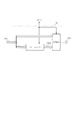
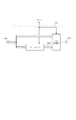
画像表示システムは、画像出力装置101、画像制御装置105及び表示装置109とから構成される。
The image display system includes an
ここで、画像出力装置101としては、デジタルスチルカメラ(DSC)やデジタルビデオカメラ(DVC)などのデジタル画像信号を出力する小型でバッテリー駆動の映像機器が好ましく用いられる。また、画像出力装置101と画像制御装置105の間の信号伝送や画像制御装置105と表示装置109の間の信号伝送で用いられるデジタルインターフェイスは、例えばHDMIのような動画像用のインターフェイスである。
Here, as the
画像出力装置101はCPU102の指示により、記憶部103に蓄えた画像を、トランスミッター104を介して外部に出力する。トランスミッター104は例えばHDMIならば、差動伝送のTMDS信号に変換して非圧縮で画像信号を送出する。
The
画像出力装置101から出力されたデジタルの画像信号は、画像信号を伝送する信号線110を介して画像制御装置105に入力される。
A digital image signal output from the
画像制御装置105では、入力部であるレシーバー107が画像信号を受け取る。レシーバー107は後段の画像処理部108が処理できる信号形態に変換して画像信号を画像処理部108に渡す。画像処理部108はCPU106の指示に従って下記の画像処理を行い、表示装置109に画像信号を渡す。表示装置109は入力された画像信号に基いて画像を表示する。
In the
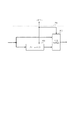
図2に画像処理部108の詳細を記す。画像処理部108では、解像度変換や輝度調整など数々の画像処理を行うが、ここでは説明を簡略にするために本発明に最も関係する画像処理についてのみ記載する。
Details of the
画像処理装置108は、少なくとも一画面分の画像の画像信号を格納するフレームメモリ201と、画像信号を切り替えて出力する切替部202で構成される。
The
画像制御装置105に入力される画像信号が動画の場合、画像出力装置101のトランスミッター104は動画出力用のインターフェイスなので通常の画像出力として扱い、コントロール信号を伝送する信号線111は使用しない。
When the image signal input to the
図3は画像制御装置105に動画データが入力された場合における、画像処理部108内部の信号の流れを説明した図である。
FIG. 3 is a diagram illustrating the flow of signals inside the
動画像入力の場合、画像処理部108では処理は行わずに入力された画像信号S301をそのまま出力する。即ち、切替部202は入力された画像信号S301と、フレームメモリ201から読み出した1フレーム前の画像信号S304とから入力画像信号S301を選択して、出力画像信号S305として出力する。
In the case of moving image input, the
ここでは、動画入力の場合もフレームメモリ201に画像信号を書き込み・読み出す動作を行うが、動画の場合はCPU106からの指示によって書き込み・読み出し動作を停止するようにしてもよい。
Here, the operation of writing / reading image signals to / from the
一方、画像制御装置105に入力される画像が静止画の場合、画像出力装置101から信号線111を用いて、出力画像が静止画であることが画像制御装置105に通知される。レシーバー107は、入力画像が静止画である旨の情報をCPU106に知らせる。CPU106はその情報に従って画像処理部108に指示を出す。
On the other hand, when the image input to the
静止画像入力の場合、画像処理部108ではCPU106の指示に従ってフレームメモリ201への画像データの書き込みを停止する。ここでフレームメモリ201には静止画像が少なくとも1フレーム分、蓄えられているものとする。次にCPU106は切替部202に指示を出し、入力画像信号S301と、フレームメモリ201から読み出された少なくとも1フレーム前の画像信号S304とから、画像信号S304を選択して出力画像信号S305として出力する。
In the case of still image input, the
切替部202の出力切り替えが完了すると、CPU106はレシーバー107に指示を出し、信号線111を介して通知信号を出力し、画像制御装置105がフレームメモリ201からの画像信号を出力中であることを画像出力装置101に通知する。
When the output switching of the switching unit 202 is completed, the
画像出力装置101ではトランスミッター104を介してCPU102にその情報が伝えられる。CPU102は画像信号を出力しつづける必要がないので、画像信号の出力を停止したパワーセーブモードに移行し、ユーザーの新たな入力待ちの状態になる。
In the
図4は画像出力装置101の動作を説明したフローチャートである。
FIG. 4 is a flowchart for explaining the operation of the
ケーブルを介して本発明による画像制御装置105への接続が検出(S501)されると、ユーザーからの出力要求が静止画か動画かの判断(S502)が行われる。
When the connection to the
ここでユーザーからの要求が動画出力ならば、デジタルインターフェイスから動画像信号が送出(S503)される。 If the user request is a moving image output, a moving image signal is sent from the digital interface (S503).
また、ユーザーからの要求が静止画出力ならば、デジタルインターフェイスから静止画像信号が送出(S504)される。静止画出力の時は画像制御装置105に送出信号が静止画であることを知らせる静止画像判別信号が送出(S505)される。静止画判別信号を受け取った画像制御装置105は、前記静止画像信号をメモリーに格納したか否かをメモリー格納済信号として画像出力装置101に通知する。画像出力装置101は前記メモリー格納済信号の有無を判別(S506)する。
If the user request is still image output, a still image signal is sent from the digital interface (S504). At the time of still image output, a still image discrimination signal is transmitted to inform the
前記メモリー格納済信号が無い場合、もしくは本発明による画像制御装置105以外の機器に接続された場合、はユーザーからのキー入力待ち(S507)になる。
If there is no signal stored in the memory, or if it is connected to a device other than the
キー入力が無ければS502に移行し静止画像出力が継続して行われる。 If there is no key input, the process proceeds to S502, and still image output is continuously performed.
S508でキー入力があると、静止画判別信号の送出が停止(S508)され、ユーザーからのキー入力指示を実行して、S502に移行する。 If there is a key input in S508, the transmission of the still image discrimination signal is stopped (S508), the key input instruction from the user is executed, and the process proceeds to S502.
一方、S506で前記メモリー格納済信号が有る場合、画像出力装置101はパワーセーブモードに移行(S509)し、画像信号の出力を停止する。
On the other hand, when the memory stored signal is present in S506, the
その後、ユーザーからのキー入力待ち(S510)になる。 Thereafter, the process waits for a key input from the user (S510).
S510でユーザーからのキー入力を検出すると、パワーセーブモードを解除(S511)し、S508に移行する。 When a key input from the user is detected in S510, the power save mode is canceled (S511), and the process proceeds to S508.
図5は本発明による画像制御装置105の動作を説明したフローチャートである。
FIG. 5 is a flowchart for explaining the operation of the
ケーブルを介して画像出力装置101の接続が検出(S601)されると、送られてきた画像信号をフレームメモリ201へ格納(S602)する。
When connection of the
次に、画像出力装置101から送出される前記静止画像判別信号が有るか無いかの判断(S603)が行われる。 Next, it is determined whether or not there is the still image determination signal sent from the image output apparatus 101 (S603).
S603で前記静止画像判別信号が無かった場合は切替部202で出力画像の切り替えが行われ(S604)、動画像が表示(S605)される。さらに前記メモリー格納済信号が送出されている場合は出力が停止(S606)されて、S602に移行する。 If there is no still image discrimination signal in S603, the switching unit 202 switches the output image (S604), and the moving image is displayed (S605). Further, if the memory stored signal is transmitted, the output is stopped (S606), and the process proceeds to S602.
一方、S603で前記静止画判別信号が有った場合は切替部202で出力画像の切り替えが行われ(S607)、静止画像が表示(S608)される。さらに前記メモリー格納済信号が送出(S609)されて、S603に移行する。 On the other hand, when there is the still image discrimination signal in S603, the switching unit 202 switches the output image (S607), and the still image is displayed (S608). Further, the memory stored signal is transmitted (S609), and the process proceeds to S603.
上記説明において、画像制御装置105から送出するメモリー格納済信号を送出/停止でコントロールする信号として説明したが、特定のコマンドで制御するものとしても良い。その場合、信号の送出/停止でコントロールするのではなく、格納済みコマンドの発信/画像信号再要求コマンドの発信で制御する。これは画像出力装置101から送出する静止画判別信号においても同様である。
In the above description, the memory stored signal transmitted from the
(実施形態2)
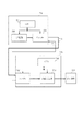
図6は、本発明の第2の実施形態に係る画像制御装置を用いた画像表示システムのブロック図である。実施形態1との相違は、画像出力装置701が記憶部703に蓄えた画像データをエンコーダー704を介して圧縮データとして出力し、画像制御装置705では、デコーダー707を介して画像信号を受信する点である。
(Embodiment 2)
FIG. 6 is a block diagram of an image display system using an image control apparatus according to the second embodiment of the present invention. The difference from the first embodiment is that the image data stored in the
また、画像出力装置701からは、静止画像判別信号は出力されず、画像制御装置705側で静止画か動画かを判定する。
The
画像処理部708は、図7に示すように、少なくとも1フレーム分の画像信号を格納するフレームメモリ801と、入力画像信号とフレームメモリ801から読み出された画像信号とを比較判定して画像信号を切り替えて出力する判定切替部802とで構成される。
As shown in FIG. 7, the
画像制御装置705に入力される画像が動画の場合、判定切替部802は入力画像信号が動画であると判定して、入力画像信号を出力すると共に、その情報をCPU706に知らせる。この場合、エンコーダー704とデコーダー707にとって信号線710を通して伝送される画像信号は通常の画像信号であるので、特にコントロールを要する必要が無く、信号線711は使用しない。
When the image input to the
図8は画像制御装置705に動画データが入力された場合における、画像処理部708内部の信号の流れを説明した図である。
FIG. 8 is a diagram for explaining the flow of signals inside the
判定切替部802は、入力された画像信号S901と、フレームメモリ801から読み出された少なくとも1フレーム前の画像信号S904とを比較して入力画像が動画か静止画かを判定し、出力の切り替えを行う。動画と判定した場合は、入力画像信号S901を選択して出力画像信号905として出力し、静止画と判定したときは、画像信号S904を選択して出力画像信号905として出力する。静止画か動画かの判定は、例えば、異なるフレーム間の画像データの平均輝度レベル(APL)を比較して判定される。即ち、APLの差が予め設定された閾値以上の時に動画と判定される。
The determination switching unit 802 determines whether the input image is a moving image or a still image by comparing the input image signal S901 with the image signal S904 read at least one frame before read from the
この閾値はユーザー調整可能なものとしても良い。 This threshold may be user adjustable.
また、比較のためのフレーム遅延量もCPU706からの指示によって設定されてもよいし、またユーザー調整可能なものとしても良い。
Further, the frame delay amount for comparison may be set by an instruction from the
さらに、フレームメモリを複数備えて比較する画像データのフレーム数を増やすことにより、静止画検出の検出精度をあげることも可能である。 Furthermore, it is possible to increase the detection accuracy of still image detection by providing a plurality of frame memories and increasing the number of frames of image data to be compared.
判定切替部802は入力画像が静止画であると判定すると、その結果をCPU706に知らせる。CPU706はフレームメモリ801へ指示を出し、フレームメモリ801への書き込みを停止する。
If the determination switching unit 802 determines that the input image is a still image, the determination switching unit 802 notifies the
さらにCPU706はデコーダー707に指示を出し、信号線711を介して画像制御装置705がフレームメモリ801を用いて出力中であることを画像出力装置701に通知する。
Further, the
画像出力装置701ではエンコーダー704を介してCPU702にその情報が伝えられる。CPU702は画像を出力しつづける必要がないので、パワーセーブモードに移行し、ユーザーの新たな入力待ちの状態になる。
In the
図9は、本実施形態における画像出力装置701の動作を説明したフローチャートである。静止画像判別信号を送出しないこと以外は実施形態1と同様なので説明は省力する。
FIG. 9 is a flowchart for explaining the operation of the
図10は本実施形態における画像制御装置705の動作を説明したフローチャートである。
FIG. 10 is a flowchart for explaining the operation of the
判定切替部802でフレームデータの比較(S1210)が行われ、その比較結果から画像出力装置701から送出される画像信号が静止画か動画かの判別(S1203)が行われる。
The determination switching unit 802 compares the frame data (S1210), and determines whether the image signal sent from the
他の実施形態1と同様の動作は説明を省略する。 Description of operations similar to those of the other embodiment 1 is omitted.
画像出力装置701がパワーセーブモード等に入り画像信号の送出が止まった場合は、S1210におけるフレームデータ比較では比較検出は行わないものとする。したがって、入力画像信号が無信号、すなわち黒画像のときは静止画と判断し、フレームメモリ701に格納されている画像を表示する。
When the
上記説明では静止画の場合にパワーセーブモードに移行する形態を述べたが、フレームメモリを複数備えて短い動画を保存して、短い動画についても上記静止画の場合と同じようにパワーセーブモードに移行できるように制御するようにすることも可能である。 In the above description, the mode of shifting to the power save mode in the case of a still image has been described. However, a short movie is stored with a plurality of frame memories, and the short movie is also switched to the power save mode as in the case of the still image. It is also possible to control to be able to shift.
101、701 画像出力装置
102、702 CPU
103、703 記憶部
104 トランスミッター
105、705 画像制御装置
106、706 CPU
107 レシーバー
108、708 画像処理部
109、709 表示装置
201、801 フレームメモリ
202 切替部
704 エンコーダー
707 デコーダー
802 判定切替部
101, 701
103, 703 Storage unit 104
Claims (9)
前記画像出力装置から出力された画像信号を入力する入力部と、
入力画像信号を格納するフレームメモリと、
前記画像信号が静止画を表示する画像信号であるときには前記フレームメモリから読み出した画像信号を出力し、前記画像信号が動画を表示する画像信号であるときには前記入力画像信号を出力する切替え部とを有することを特徴とする画像制御装置。 An image control device connectable to an image output device,
An input unit for inputting an image signal output from the image output device;
A frame memory for storing input image signals;
A switching unit that outputs an image signal read from the frame memory when the image signal is an image signal for displaying a still image, and outputs the input image signal when the image signal is an image signal for displaying a moving image; An image control apparatus comprising:
前記画像制御装置は、入力した画像信号が静止画を表示する画像信号であるときにはフレームメモリから読み出した画像信号を出力し、前記入力した画像信号が動画を表示する画像信号であるときには入力した画像信号を出力する切替え部を有し、
前記切替え部が前記フレームメモリから読み出した画像信号を出力していることを通知する通知信号を出力するものであって、
前記画像制御装置から前記通知信号を受信したときに、前記画像制御装置への画像信号の出力を停止するように制御する制御部を有することを特徴とする画像出力装置。 An image output device connectable to an image control device,
The image control device outputs an image signal read from a frame memory when the input image signal is an image signal for displaying a still image, and inputs an image when the input image signal is an image signal for displaying a moving image. A switching unit for outputting a signal;
A notification signal for notifying that the switching unit is outputting an image signal read from the frame memory;
An image output apparatus comprising: a control unit that controls to stop outputting an image signal to the image control apparatus when the notification signal is received from the image control apparatus.
前記画像出力装置から出力された画像信号を入力するステップと、
入力画像信号をフレームメモリに格納するステップと、
前記画像信号が静止画を表示する画像信号であるときには前記フレームメモリから読み出した画像信号を出力し、前記画像信号が動画を表示する画像信号であるときには前記入力画像信号を出力するステップとを有することを特徴とする画像制御装置の制御方法。
An image control device control method connectable to an image output device,
Inputting an image signal output from the image output device;
Storing an input image signal in a frame memory;
Outputting the image signal read from the frame memory when the image signal is an image signal for displaying a still image, and outputting the input image signal when the image signal is an image signal for displaying a moving image. And a control method for the image control apparatus.
Priority Applications (5)
| Application Number | Priority Date | Filing Date | Title |
|---|---|---|---|
| JP2006061226A JP2007240741A (en) | 2006-03-07 | 2006-03-07 | Image controller and control method |
| US12/280,830 US20090033969A1 (en) | 2006-03-07 | 2007-02-28 | Image control apparatus and image control method |
| EP07715258A EP1991981A1 (en) | 2006-03-07 | 2007-02-28 | Image control apparatus and image control method |
| PCT/JP2007/054367 WO2007105548A1 (en) | 2006-03-07 | 2007-02-28 | Image control apparatus and image control method |
| CN2007800079793A CN101395656B (en) | 2006-03-07 | 2007-02-28 | Image control apparatus and image control method |
Applications Claiming Priority (1)
| Application Number | Priority Date | Filing Date | Title |
|---|---|---|---|
| JP2006061226A JP2007240741A (en) | 2006-03-07 | 2006-03-07 | Image controller and control method |
Publications (2)
| Publication Number | Publication Date |
|---|---|
| JP2007240741A true JP2007240741A (en) | 2007-09-20 |
| JP2007240741A5 JP2007240741A5 (en) | 2008-11-13 |
Family
ID=38093504
Family Applications (1)
| Application Number | Title | Priority Date | Filing Date |
|---|---|---|---|
| JP2006061226A Pending JP2007240741A (en) | 2006-03-07 | 2006-03-07 | Image controller and control method |
Country Status (5)
| Country | Link |
|---|---|
| US (1) | US20090033969A1 (en) |
| EP (1) | EP1991981A1 (en) |
| JP (1) | JP2007240741A (en) |
| CN (1) | CN101395656B (en) |
| WO (1) | WO2007105548A1 (en) |
Cited By (8)
| Publication number | Priority date | Publication date | Assignee | Title |
|---|---|---|---|---|
| JP2008283561A (en) * | 2007-05-11 | 2008-11-20 | Sony Corp | Communication system, video signal transmission method, transmitter, transmitting method, receiver, and receiving method |
| JP2011259155A (en) * | 2010-06-08 | 2011-12-22 | Sharp Corp | Content reproduction device, content reproduction system, reproduction method, program, and recording medium |
| US8217948B2 (en) * | 2008-04-08 | 2012-07-10 | Samsung Electronics Co., Ltd. | Display interface system, display device and display system |
| US8359628B2 (en) | 2007-10-05 | 2013-01-22 | Sony Corporation | Display device and transmitting device |
| JP2013076855A (en) * | 2011-09-30 | 2013-04-25 | Mitsubishi Electric Corp | Video signal processing apparatus |
| WO2013076881A1 (en) * | 2011-11-25 | 2013-05-30 | パナソニック株式会社 | Transmission device and reception device for baseband video data, and transmission/reception system |
| KR101307557B1 (en) * | 2012-03-09 | 2013-09-12 | 엘지디스플레이 주식회사 | Display device and method for controlling panel self refresh operation thereof |
| JP2015075770A (en) * | 2013-10-11 | 2015-04-20 | 三星電子株式会社Samsung Electronics Co.,Ltd. | Image processing device, electronic device containing image processing device, and image processing method |
Families Citing this family (5)
| Publication number | Priority date | Publication date | Assignee | Title |
|---|---|---|---|---|
| TW201001155A (en) * | 2008-06-24 | 2010-01-01 | Qisda Corp | Digital frame and power saving method thereof |
| TW201035956A (en) * | 2009-03-27 | 2010-10-01 | Hannstar Display Corp | Liquid crystal display device having low power consumption and method thereof |
| CN102213995A (en) * | 2010-04-09 | 2011-10-12 | 宏碁股份有限公司 | Display system and electricity saving method thereof |
| CN102810294A (en) * | 2012-08-01 | 2012-12-05 | 京东方科技集团股份有限公司 | Displaying method, displaying device and displaying system |
| CN109272972B (en) * | 2018-11-30 | 2021-04-09 | 北京集创北方科技股份有限公司 | Display device and control method thereof |
Citations (4)
| Publication number | Priority date | Publication date | Assignee | Title |
|---|---|---|---|---|
| JP2002158936A (en) * | 2000-11-17 | 2002-05-31 | Canon Inc | Digital television system, method for displaying image and storage medium |
| JP2003162272A (en) * | 2001-09-14 | 2003-06-06 | Nec Corp | Image processor, image transmitting device, image receiving device, and image processing method |
| JP2004271930A (en) * | 2003-03-10 | 2004-09-30 | Nec Electronics Corp | Driving circuit of display device |
| JP2005316176A (en) * | 2004-04-28 | 2005-11-10 | Toshiba Corp | Electronic equipment and display control method |
Family Cites Families (17)
| Publication number | Priority date | Publication date | Assignee | Title |
|---|---|---|---|---|
| US5206730A (en) * | 1989-11-10 | 1993-04-27 | Konica Corporation | Still video camera having one-shot and serial shot modes |
| JP3162231B2 (en) | 1993-08-06 | 2001-04-25 | 株式会社日立製作所 | Digital image display system |
| US5880702A (en) * | 1994-10-20 | 1999-03-09 | Canon Kabushiki Kaisha | Display control apparatus and method |
| JPH09163209A (en) | 1995-12-08 | 1997-06-20 | Canon Inc | Digital camera, image pickup device and image pickup means controller |
| US6756974B2 (en) * | 1997-09-24 | 2004-06-29 | Canon Kabushiki Kaisha | Display control apparatus and method |
| EP1583094B1 (en) * | 1998-04-21 | 2007-06-20 | Victor Company of Japan, Ltd. | Power saving system for optical disc recording/reproducing apparatus |
| JP2001094989A (en) * | 1999-09-20 | 2001-04-06 | Toshiba Corp | Dynamic image transmitter and dynamic image communications equipment |
| US7088322B2 (en) * | 2000-05-12 | 2006-08-08 | Semiconductor Energy Laboratory Co., Ltd. | Semiconductor device |
| US6903732B2 (en) * | 2001-01-15 | 2005-06-07 | Matsushita Electric Industrial Co., Ltd. | Image display device |
| JP3578141B2 (en) * | 2001-02-22 | 2004-10-20 | セイコーエプソン株式会社 | Display driver, display unit and electronic device |
| EP1331570B1 (en) * | 2002-01-18 | 2005-03-23 | Hewlett-Packard Company | Data processing system and method for controlling display devices |
| JP2004015332A (en) * | 2002-06-05 | 2004-01-15 | Olympus Corp | Table type display apparatus and assembling method therefor |
| JP4838132B2 (en) * | 2003-09-10 | 2011-12-14 | クゥアルコム・インコーポレイテッド | High speed data rate interface |
| US7173613B2 (en) * | 2003-09-30 | 2007-02-06 | Lenovosingapore Pte Ltd | Peripheral device including a user interface for controlling a computer system unit optionally attached to the peripheral device |
| KR100541956B1 (en) * | 2004-06-22 | 2006-01-12 | 삼성전자주식회사 | DVD reproducing device for transforming external input signal and method thereof |
| US8098964B2 (en) * | 2006-02-06 | 2012-01-17 | Microsoft Corp. | Raw image processing |
| JP4890880B2 (en) * | 2006-02-16 | 2012-03-07 | キヤノン株式会社 | Image transmitting apparatus, image transmitting method, program, and storage medium |
-
2006
- 2006-03-07 JP JP2006061226A patent/JP2007240741A/en active Pending
-
2007
- 2007-02-28 WO PCT/JP2007/054367 patent/WO2007105548A1/en active Search and Examination
- 2007-02-28 CN CN2007800079793A patent/CN101395656B/en not_active Expired - Fee Related
- 2007-02-28 US US12/280,830 patent/US20090033969A1/en not_active Abandoned
- 2007-02-28 EP EP07715258A patent/EP1991981A1/en not_active Withdrawn
Patent Citations (4)
| Publication number | Priority date | Publication date | Assignee | Title |
|---|---|---|---|---|
| JP2002158936A (en) * | 2000-11-17 | 2002-05-31 | Canon Inc | Digital television system, method for displaying image and storage medium |
| JP2003162272A (en) * | 2001-09-14 | 2003-06-06 | Nec Corp | Image processor, image transmitting device, image receiving device, and image processing method |
| JP2004271930A (en) * | 2003-03-10 | 2004-09-30 | Nec Electronics Corp | Driving circuit of display device |
| JP2005316176A (en) * | 2004-04-28 | 2005-11-10 | Toshiba Corp | Electronic equipment and display control method |
Cited By (16)
| Publication number | Priority date | Publication date | Assignee | Title |
|---|---|---|---|---|
| US8856840B2 (en) | 2007-05-11 | 2014-10-07 | Sony Corporation | Communication system, video signal transmission method, transmitter, transmitting method, receiver, and receiving method |
| JP2008283561A (en) * | 2007-05-11 | 2008-11-20 | Sony Corp | Communication system, video signal transmission method, transmitter, transmitting method, receiver, and receiving method |
| US8359628B2 (en) | 2007-10-05 | 2013-01-22 | Sony Corporation | Display device and transmitting device |
| US8869209B2 (en) | 2007-10-05 | 2014-10-21 | Sony Corporation | Display device and transmitting device |
| US8217948B2 (en) * | 2008-04-08 | 2012-07-10 | Samsung Electronics Co., Ltd. | Display interface system, display device and display system |
| KR101453074B1 (en) | 2008-04-08 | 2014-10-23 | 삼성전자주식회사 | Display interface system display device and display system |
| JP2011259155A (en) * | 2010-06-08 | 2011-12-22 | Sharp Corp | Content reproduction device, content reproduction system, reproduction method, program, and recording medium |
| JP2013076855A (en) * | 2011-09-30 | 2013-04-25 | Mitsubishi Electric Corp | Video signal processing apparatus |
| WO2013076882A1 (en) * | 2011-11-25 | 2013-05-30 | パナソニック株式会社 | Baseband video data transmission device and receiving device, and transceiver system |
| WO2013076881A1 (en) * | 2011-11-25 | 2013-05-30 | パナソニック株式会社 | Transmission device and reception device for baseband video data, and transmission/reception system |
| US8872982B2 (en) | 2011-11-25 | 2014-10-28 | Panasonic Corporation | Transmission device and reception device for baseband video data, and transmission/reception system |
| US8902368B2 (en) | 2011-11-25 | 2014-12-02 | Panasonic Corporation | Baseband video data transmission device and reception device, and transceiver system with reduced power consumption by intermittent transmission reception of a video signal |
| JP5695211B2 (en) * | 2011-11-25 | 2015-04-01 | パナソニックIpマネジメント株式会社 | Baseband video data transmission device, reception device, and transmission / reception system |
| JPWO2013076882A1 (en) * | 2011-11-25 | 2015-04-27 | パナソニックIpマネジメント株式会社 | Baseband video data transmission device, reception device, and transmission / reception system |
| KR101307557B1 (en) * | 2012-03-09 | 2013-09-12 | 엘지디스플레이 주식회사 | Display device and method for controlling panel self refresh operation thereof |
| JP2015075770A (en) * | 2013-10-11 | 2015-04-20 | 三星電子株式会社Samsung Electronics Co.,Ltd. | Image processing device, electronic device containing image processing device, and image processing method |
Also Published As
| Publication number | Publication date |
|---|---|
| CN101395656A (en) | 2009-03-25 |
| WO2007105548A1 (en) | 2007-09-20 |
| EP1991981A1 (en) | 2008-11-19 |
| CN101395656B (en) | 2011-01-05 |
| US20090033969A1 (en) | 2009-02-05 |
Similar Documents
| Publication | Publication Date | Title |
|---|---|---|
| JP2007240741A (en) | Image controller and control method | |
| JP4829806B2 (en) | Data processing apparatus and computer program | |
| US10212381B2 (en) | Image transfer apparatus with CEC communication function | |
| US8453008B2 (en) | Communication apparatus and control method using consumer electronics protocol | |
| US10509614B2 (en) | Video display apparatus-apparatus communication | |
| US9778894B2 (en) | System and method for outputting extended display identification data to another electronic device to achieve power savings | |
| JP2009253390A (en) | Electronic device, communication system, communication method, and program | |
| JP2010028553A (en) | Communication apparatus | |
| EP1672922A2 (en) | Electronic device and method of controlling same | |
| US20150163450A1 (en) | Video display system, source device, sink device, and video display method | |
| US20240040079A1 (en) | Reception Device, Method for Controlling Reception Device, and Transmission/Reception System | |
| JP5335609B2 (en) | Communication device | |
| JP2010154241A (en) | Communication apparatus | |
| JP6811607B2 (en) | Receiver and receiving method | |
| CN108780348B (en) | Image transmission apparatus, image transmission system, and method of controlling image transmission apparatus | |
| CN107846588B (en) | Method and device for acquiring serial port record information in television | |
| JP2010004353A (en) | Image processor, and control method thereof | |
| US20120257118A1 (en) | Image processing apparatus and method, recording medium, and program | |
| US11688330B2 (en) | Display apparatus and controlling method thereof | |
| JP2019220752A (en) | Information processing device | |
| JP5693676B2 (en) | Communication apparatus and control method | |
| JP2014146921A (en) | Communication device, control method, and program | |
| JP2018191021A (en) | Communication device | |
| JP2016208434A (en) | Electronic apparatus, method, and program | |
| JP2004295143A (en) | Image output device, image output method, image transmission device, and image transmission method |
Legal Events
| Date | Code | Title | Description |
|---|---|---|---|
| A521 | Written amendment |
Free format text: JAPANESE INTERMEDIATE CODE: A523 Effective date: 20080926 |
|
| A621 | Written request for application examination |
Free format text: JAPANESE INTERMEDIATE CODE: A621 Effective date: 20080926 |
|
| RD04 | Notification of resignation of power of attorney |
Free format text: JAPANESE INTERMEDIATE CODE: A7424 Effective date: 20100201 |
|
| RD01 | Notification of change of attorney |
Free format text: JAPANESE INTERMEDIATE CODE: A7421 Effective date: 20100630 |
|
| A131 | Notification of reasons for refusal |
Free format text: JAPANESE INTERMEDIATE CODE: A131 Effective date: 20110906 |
|
| A521 | Written amendment |
Free format text: JAPANESE INTERMEDIATE CODE: A523 Effective date: 20111014 |
|
| A02 | Decision of refusal |
Free format text: JAPANESE INTERMEDIATE CODE: A02 Effective date: 20120214 |