CN101155672B - Parallel-kinematical machine - Google Patents
Parallel-kinematical machine Download PDFInfo
- Publication number
- CN101155672B CN101155672B CN2005800395787A CN200580039578A CN101155672B CN 101155672 B CN101155672 B CN 101155672B CN 2005800395787 A CN2005800395787 A CN 2005800395787A CN 200580039578 A CN200580039578 A CN 200580039578A CN 101155672 B CN101155672 B CN 101155672B
- Authority
- CN
- China
- Prior art keywords
- machine
- reinforcement
- adjusting device
- parallel motion
- motion according
- Prior art date
- Legal status (The legal status is an assumption and is not a legal conclusion. Google has not performed a legal analysis and makes no representation as to the accuracy of the status listed.)
- Expired - Fee Related
Links
- 230000002787 reinforcement Effects 0.000 claims description 100
- 230000007704 transition Effects 0.000 claims 1
- 230000003014 reinforcing effect Effects 0.000 abstract description 5
- 238000005452 bending Methods 0.000 description 6
- 238000004519 manufacturing process Methods 0.000 description 2
- 239000000463 material Substances 0.000 description 2
- 229920000049 Carbon (fiber) Polymers 0.000 description 1
- 229910000831 Steel Inorganic materials 0.000 description 1
- 230000005540 biological transmission Effects 0.000 description 1
- 239000004917 carbon fiber Substances 0.000 description 1
- 239000002131 composite material Substances 0.000 description 1
- 230000008878 coupling Effects 0.000 description 1
- 238000010168 coupling process Methods 0.000 description 1
- 238000005859 coupling reaction Methods 0.000 description 1
- 238000005516 engineering process Methods 0.000 description 1
- VNWKTOKETHGBQD-UHFFFAOYSA-N methane Chemical compound C VNWKTOKETHGBQD-UHFFFAOYSA-N 0.000 description 1
- NJPPVKZQTLUDBO-UHFFFAOYSA-N novaluron Chemical compound C1=C(Cl)C(OC(F)(F)C(OC(F)(F)F)F)=CC=C1NC(=O)NC(=O)C1=C(F)C=CC=C1F NJPPVKZQTLUDBO-UHFFFAOYSA-N 0.000 description 1
- 230000000149 penetrating effect Effects 0.000 description 1
- 238000004904 shortening Methods 0.000 description 1
- 239000010959 steel Substances 0.000 description 1
Images


Classifications
-
- B—PERFORMING OPERATIONS; TRANSPORTING
- B25—HAND TOOLS; PORTABLE POWER-DRIVEN TOOLS; MANIPULATORS
- B25J—MANIPULATORS; CHAMBERS PROVIDED WITH MANIPULATION DEVICES
- B25J9/00—Programme-controlled manipulators
- B25J9/10—Programme-controlled manipulators characterised by positioning means for manipulator elements
-
- B—PERFORMING OPERATIONS; TRANSPORTING
- B25—HAND TOOLS; PORTABLE POWER-DRIVEN TOOLS; MANIPULATORS
- B25J—MANIPULATORS; CHAMBERS PROVIDED WITH MANIPULATION DEVICES
- B25J17/00—Joints
- B25J17/02—Wrist joints
- B25J17/0258—Two-dimensional joints
- B25J17/0266—Two-dimensional joints comprising more than two actuating or connecting rods
-
- B—PERFORMING OPERATIONS; TRANSPORTING
- B23—MACHINE TOOLS; METAL-WORKING NOT OTHERWISE PROVIDED FOR
- B23Q—DETAILS, COMPONENTS, OR ACCESSORIES FOR MACHINE TOOLS, e.g. ARRANGEMENTS FOR COPYING OR CONTROLLING; MACHINE TOOLS IN GENERAL CHARACTERISED BY THE CONSTRUCTION OF PARTICULAR DETAILS OR COMPONENTS; COMBINATIONS OR ASSOCIATIONS OF METAL-WORKING MACHINES, NOT DIRECTED TO A PARTICULAR RESULT
- B23Q1/00—Members which are comprised in the general build-up of a form of machine, particularly relatively large fixed members
- B23Q1/25—Movable or adjustable work or tool supports
- B23Q1/26—Movable or adjustable work or tool supports characterised by constructional features relating to the co-operation of relatively movable members; Means for preventing relative movement of such members
-
- B—PERFORMING OPERATIONS; TRANSPORTING
- B23—MACHINE TOOLS; METAL-WORKING NOT OTHERWISE PROVIDED FOR
- B23Q—DETAILS, COMPONENTS, OR ACCESSORIES FOR MACHINE TOOLS, e.g. ARRANGEMENTS FOR COPYING OR CONTROLLING; MACHINE TOOLS IN GENERAL CHARACTERISED BY THE CONSTRUCTION OF PARTICULAR DETAILS OR COMPONENTS; COMBINATIONS OR ASSOCIATIONS OF METAL-WORKING MACHINES, NOT DIRECTED TO A PARTICULAR RESULT
- B23Q1/00—Members which are comprised in the general build-up of a form of machine, particularly relatively large fixed members
- B23Q1/25—Movable or adjustable work or tool supports
- B23Q1/44—Movable or adjustable work or tool supports using particular mechanisms
- B23Q1/50—Movable or adjustable work or tool supports using particular mechanisms with rotating pairs only, the rotating pairs being the first two elements of the mechanism
- B23Q1/54—Movable or adjustable work or tool supports using particular mechanisms with rotating pairs only, the rotating pairs being the first two elements of the mechanism two rotating pairs only
- B23Q1/545—Movable or adjustable work or tool supports using particular mechanisms with rotating pairs only, the rotating pairs being the first two elements of the mechanism two rotating pairs only comprising spherical surfaces
- B23Q1/5462—Movable or adjustable work or tool supports using particular mechanisms with rotating pairs only, the rotating pairs being the first two elements of the mechanism two rotating pairs only comprising spherical surfaces with one supplementary sliding pair
-
- Y—GENERAL TAGGING OF NEW TECHNOLOGICAL DEVELOPMENTS; GENERAL TAGGING OF CROSS-SECTIONAL TECHNOLOGIES SPANNING OVER SEVERAL SECTIONS OF THE IPC; TECHNICAL SUBJECTS COVERED BY FORMER USPC CROSS-REFERENCE ART COLLECTIONS [XRACs] AND DIGESTS
- Y10—TECHNICAL SUBJECTS COVERED BY FORMER USPC
- Y10T—TECHNICAL SUBJECTS COVERED BY FORMER US CLASSIFICATION
- Y10T409/00—Gear cutting, milling, or planing
- Y10T409/30—Milling
- Y10T409/306664—Milling including means to infeed rotary cutter toward work
- Y10T409/307672—Angularly adjustable cutter head
-
- Y—GENERAL TAGGING OF NEW TECHNOLOGICAL DEVELOPMENTS; GENERAL TAGGING OF CROSS-SECTIONAL TECHNOLOGIES SPANNING OVER SEVERAL SECTIONS OF THE IPC; TECHNICAL SUBJECTS COVERED BY FORMER USPC CROSS-REFERENCE ART COLLECTIONS [XRACs] AND DIGESTS
- Y10—TECHNICAL SUBJECTS COVERED BY FORMER USPC
- Y10T—TECHNICAL SUBJECTS COVERED BY FORMER US CLASSIFICATION
- Y10T409/00—Gear cutting, milling, or planing
- Y10T409/30—Milling
- Y10T409/309576—Machine frame
-
- Y—GENERAL TAGGING OF NEW TECHNOLOGICAL DEVELOPMENTS; GENERAL TAGGING OF CROSS-SECTIONAL TECHNOLOGIES SPANNING OVER SEVERAL SECTIONS OF THE IPC; TECHNICAL SUBJECTS COVERED BY FORMER USPC CROSS-REFERENCE ART COLLECTIONS [XRACs] AND DIGESTS
- Y10—TECHNICAL SUBJECTS COVERED BY FORMER USPC
- Y10T—TECHNICAL SUBJECTS COVERED BY FORMER US CLASSIFICATION
- Y10T74/00—Machine element or mechanism
- Y10T74/20—Control lever and linkage systems
- Y10T74/20207—Multiple controlling elements for single controlled element
- Y10T74/20305—Robotic arm
- Y10T74/20317—Robotic arm including electric motor
Landscapes
- Engineering & Computer Science (AREA)
- Mechanical Engineering (AREA)
- Robotics (AREA)
- Machine Tool Units (AREA)
- Manipulator (AREA)
- Lenses (AREA)
- Sorption Type Refrigeration Machines (AREA)
- Compression-Type Refrigeration Machines With Reversible Cycles (AREA)
- Transmission Devices (AREA)
- Pivots And Pivotal Connections (AREA)
- Transplanting Machines (AREA)
- Laser Beam Processing (AREA)
- Soil Working Implements (AREA)
- Lifting Devices For Agricultural Implements (AREA)
- Working Measures On Existing Buildindgs (AREA)
- Extrusion Moulding Of Plastics Or The Like (AREA)
- Machines For Laying And Maintaining Railways (AREA)
Abstract
A parallel-kinematical machine (1) that includes at least three setting devices (4.1, 4.2, 4.3) which can be lengthened and shortened individually, wherein each setting device (4.1, 4.2, 4.3) is connected to a positioning head (11) via a first joint (8, 9, 10), wherein each setting device (4.1, 4.2, 4.3) is connected to a base (2) via a universal joint (3.1, 3.2, 3.3), and wherein the positioning head (11) is movable within a working range in response to manoeuvring of the setting devices (4.1, 4.2, 4.3), wherein at least two reinforcing beams (5.1, 5.2, 5.2.1, 5.2.2) are connected to the positioning head (11) via a respective beam rotation bearing (100.1, 100.2), each having solely one degree of freedom, wherein each reinforcing beam (5.1, 5.2, 5.2.1, 5.2.2) is adapted to slide transversely in a beam bearing (17.1, 17.2, 17.2.1, 17.2.2) in the base (2) when one or more of the setting devices (4.1, 4.2, 4.3) is lengthened or shortened, wherein each beam bearing (17.1, 17.2, 17.2.1, 17.2.2) is connected to the base (2) via a beam-universal-joint (BU1, BU2) and wherein the beam bearing (17.2, 17.2.1, 17.2.2) of at least one reinforcing beam (5.2, 5.2.1, 5.2.2) is rotatable about an axis that extends parallel with the longitudinal axis of said reinforcing beam (5.2, 5.2.1, 5.2.2).
Description
Technical field
The present invention relates to machine tool field, particularly relate to the robot that is used for industry.
Background technology
US Patent specification U.S.4,732,525 (corresponding SE 452279) have lectured a kind of machine of parallel motion of robot form of conventional design.This robot comprises three adjusting devices that can extend and shorten, and a central tube that has positioning head at the one end.This central tube also is installed into centre bearing by the universal joint form along its axially-movable, and this universal joint can provide the three degree of freedom with respect to machinery bed.Each adjusting device can provide the joint of three degree of freedom to be connected with described positioning head by one, and is connected with machinery bed by a joint with two frees degree, so that described positioning head can be moved in limited working range.Described adjusting device is only adjusted pulling force and pressure, and central tube is adjusted all revolving forces and be applied to the bending stress that produces on the positioning head owing to load.
The accuracy that this machine moves depends primarily on its rigidity, and rigidity depends on the quantity of available bearing/free degree, depends on that also component materials minimizes the ability of distorting stress and bending stress on the crucial direction.For example, what can mention is, the big side force of positioning head causes central tube the tendency of rotating between the connector crooked and/or its gyrobearing and itself and described adjusting device in machinery bed to occur.
Therefore, the rigidity of described conventional machine especially depends on the design that is connected of adjusting device and positioning head, also depends on the self-stiffness of central tube self.In order to strengthen the rigidity of this conventional machine, be necessary at first in each joint, to use stricter tolerance, next is to use firmer central tube, brings weight to increase thereupon.
This central tube can be made firmlyer by using harder material and/or the thickness by increasing central tube and/or increasing its diameter.
Yet the improvement of all these machine rigidity all causes higher cost, heavier machine and the minimizing that can handle the working region of this positioning head.
The machine of known similar parallel motion also derives from, for example UK Patent Application 8319708 (2,143,498), US 4,569,627 and NO 148216.
Yet, do not have in these known machines a kind of have allow the rigidity levels that the modern machines expectation reaches and the basic structure of thing followed precision level.
Summary of the invention
One object of the present invention is to provide a kind of machine of parallel motion, and the desired precision of its rigidity and its thing followed is greater than the rigidity and the precision of the machine of the parallel motion of previously known, and has the simple structure that can realize relatively low manufacturing cost.
Further purpose is to provide a kind of like this machine, and this machine does not have central tube, improving the flexibility of positioning head in its working range, and also helps to realize simple structure and relatively low manufacturing cost thereupon.
Also have, another purpose is to reduce the moving-mass of this machine.
The present invention relates to a kind of machine of parallel motion, it comprises at least three adjusting devices, and described adjusting device can extend and shorten on its longitudinal direction individually.Each adjusting device is connected with positioning head by first joint, also is connected with machinery bed by suitable universal joint, and the form of this universal joint can be slewing equipment or ball screw.Therefore, this positioning head can be moved in working range by handling this adjusting device.At least two reinforcements are connected with described positioning head by beam swivel bearing separately, and each beam swivel bearing only has one degree of freedom.Each reinforcement is arranged to, and laterally slides in the beam bearing of base support when one or more described adjusting devices is elongated or shortened.In addition, each beam bearing is connected with machinery bed by the beam universal joint, and the axis that the beam bearing of at least one reinforcement can extend in parallel around the longitudinal axis with this reinforcement rotates.
This notion produces several feasible basic embodiment about concerning between machinery bed, adjusting device, reinforcement and the positioning head, these basic embodiment are the correlation about these parts on the one hand, be that this will become obvious according to the part that is described below with reference to Fig. 6 about the correlation of parts bearing in the machinery bed and in the positioning head on the other hand.
Specific embodiment described below comprises three adjusting devices, and each adjusting device is connected with its reinforcement separately, and wherein second adjusting device also has additional reinforcement.
Universal joint comprises outer pivoted member, should be installed in the aforementioned base so that around outer axis of rotation rotation by outer pivoted member, and further comprise interior pivoted member, pivoted member is installed in the described outer pivoted member so that around rotating with the rectangular interior axis of rotation of described outer axis of rotation in this.In this case, the beam bearing preferably is connected with the interior pivoted member of universal joint.Under the situation of other embodiment, the beam bearing can separate with the universal joint of described adjusting device, but link to each other with the universal joint of self, this self the universal joint and the universal joint of this adjusting device concern at interval, yet described self universal joint needs the beam swivel bearing of self that this reinforcement is connected with positioning head.
To become according to illustrated embodiment and be apparent that first joint only has one degree of freedom, and eliminate and to give this machine rigidity in the use central tube thus.
Each reinforcement is suitable for presenting bending strength on a first direction, this bending strength considerably beyond reinforcement with the rectangular direction of this first direction on bending strength.This makes described reinforcement can have the shape of cross section or the oval shape of cross section of essentially rectangular.Yet, should be appreciated that, can expect that other shape of cross sections also fall within the scope of the present invention, for example I-beam (I-beam).Described reinforcement is preferably made by the composite with carbon fiber reinforcement.
According to the embodiment of detailed demonstration, this machine comprises three adjusting devices, and each adjusting device forever is connected with reinforcement in described first joint.One of them adjusting device also has additional reinforcement, so that all obtain roughly the same rigidity on all directions.As noted above, can expect that this machine only has two reinforcements each other in the right angle setting.The beam bearing of at least one reinforcement can be around the longitudinal axis rotation of self, perhaps be centered around in its base bearing with the parallel axis rotation of described self longitudinal axis.In this illustrated embodiment, this can be around described adjusting device rotation in interior pivoted member to reinforcement.
Each adjusting device of illustrated embodiment is made of screw-nut body, and wherein nut forever is connected with interior pivoted member.Yet, should be appreciated that, can imagine that fully other Machinery Design with other types adjusting device also fall in the scope of the invention.For example, can use linear motor to substitute illustrated screw-nut body as adjusting device.This linear motor even can be made of reinforcement perhaps comprises the part of reinforcement.
Each reinforcement comprises first sliding members of at least one longitudinal extension, it for example is the steel slide bar that can bonded or firmly be screwed on the beam, described first sliding members is connected with second sliding members (for example guide rail) with the shape lock mode, but can slide by relative second sliding members, wherein second sliding members is connected with described nut by intermediate bearing directly or indirectly.At second sliding members indirectly by under intermediate bearing and the situation that nut is connected, described second sliding members leads in the shape mode with respect to described nut owing to can tilt around adjusting device, and this can become obvious according to the illustrated embodiment that has the universal joint bearing of two reinforcements.Though illustrated embodiment has shown by allowing described reinforcement to rotate in interior pivoted member, the axis rotation that reinforcement can extend in parallel around the symmetrical longitudinal axis with this reinforcement, but be appreciated that corresponding rotation also can just rotate it in the outer pivoted member of described joint to realize by whole universal joint is installed in machinery bed.
Described screw or nut are rotatably driven by the adjusting device motor.When drive by motor be screw the time, motor is connected with an end of this screw, and the other end of described screw is supported by spring bearing.In the embodiment that shows in detail, the adjusting device motor is installed in the motor frame, one end of motor frame has the part of described first joint, and this motor frame comprises also and connect the surface that one or more reinforcements will be abutted against on described the connections surface and fix.Perhaps, the motor frame that holds the adjusting device motor also can be installed in respect to shown in the other end of screw of part speech, thus in this case, " the no motor " of screw held and is connected with described first joint.When drive by motor be nut the time, described driving can for example wait by belt transmission and realize, so that can easily change the ratio of adjusting device and motor.
Two first joints in first joint at positioning head place comprise the joint axis that is parallel to each other, and the 3rd described first joint at described positioning head place comprises the joint axis that meets at right angles and extend with other two joint axis.In addition, the joint axis line parallel of first joint of this adjusting device in the joint that the interior axis of rotation of the universal joint of each adjusting device and those do not allow to tilt, wherein do not allow just not allow reinforcement center on this joint in the parallel axis rotation of longitudinal axis of self symmetry.
The embodiment that shows provides a kind of machine of parallel motion in detail, the universal joint of this machine comprises two joint and the joints with three degree of freedom of having two frees degree separately, and each the beam swivel bearing for this machine only has one degree of freedom, promptly at this positioning head place.
Should be appreciated that according to the present invention, the quantity of the reinforcement that is provided and cross sectional dimensions thereof can change.If be also to be understood that the beam swivel bearing is different with described first joint, this first joint then, promptly the free degree quantity about the adjusting device joint of positioning head also can change.
Description of drawings
Now with reference to one exemplary embodiment shown in the drawings the present invention is described in more detail, wherein:
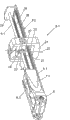
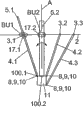
Fig. 1 illustrates according to machine embodiment of the present invention;
Fig. 2 illustrates a reinforcement according to the machine of Fig. 1, and the adjusting device that connects;
Fig. 3 is the profile of Fig. 2 mid point F3 place's reinforcement and adjusting device;
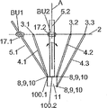
Fig. 4 illustrates another reinforcement of machine, and this beam is rotatable according to Fig. 1, and the figure illustrates the adjusting device of connection;
Fig. 5 is the profile of Fig. 4 mid point F5 place's reinforcement and adjusting device;
Fig. 6 a)-e) indicative icon according to the embodiment of five kinds of different fundamental types of the present invention; And
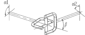
Fig. 7 illustrates the universal joint of universal joint (cardan joint) form with two frees degree.
The specific embodiment
Fig. 1 illustrates the embodiment according to the machine 1 of parallel motion of the present invention.This machine comprises base 2, and wherein three independent universal joints 3.1,3.2,3.3 are installed in penetrating in the mouth of three correspondences in this base.Adjusting device 4.1,4.2,4.3 and reinforcement or reinforcing strip 5.1,5.2.1,5.2.2,5.3 pass each universal joint and extend.When relevant universal joint is inconsistent when the universal joint relevant with adjusting device with reinforcement, be marked as BU1, BU2, BU3 as the universal joint of the reinforcement of beam universal joint.Adjusting device has the form of screw-nut body, and wherein nut and universal joint are rigidly connected.The screw of adjusting device is driven by the adjustment motor 6.1,6.2,6.3 that is installed in the motor frame 7.1,7.2,7.3, wherein the motor frame has parts 8 of first joint at the one end, and another parts 9 teamworks of these parts 8 and joint are so that around 10 rotations of joint axis.Another parts 9 of this joint are rigidly connected with positioning head 11.First joint 8,9,10 among Fig. 1 embodiment is thus as the beam swivel bearing 100.3 about reinforcement 5.3, and in the case, also conduct only has the hinge of one degree of freedom.Beam swivel bearing 100.1, the 100.2 corresponding connections that other motor framves 7.1,7.2 pass through separately with positioning head.So this positioning head 11 usually with handle 12, tool heads 13, tool coupling device 14 link to each other, thereby implementation tool is mobile in working range.Motor frame 7.1,7.2,7.3 also comprises on the limit, two opposite sides and connects surface 15, reinforcement 5.1,5.2.1,5.2.2,5.3 near and be fixed on and connect on the surface 15.Can see also that from Fig. 1 base has the medium window 16 that is used to hold cable etc.
Each reinforcement 5.1,5.2,5.3 is arranged to, and when elongating or shortening adjusting device 4.1,4.2,4.3, laterally slides among the beam bearing 17.1 in base 2,17.2.1, the 17.2.2,17.3.Be disposed among the beam universal joint BU1 consistent, BU2, the BU3 according to beam bearing 17.1,17.2.1, the 17.2.2,17.3 of Fig. 1 embodiment with the universal joint 3.1,3.2,3.3 of each adjusting device.
As can be seen from Fig. 1, one of adjusting device, promptly second adjusting device 4.2 comprises two reinforcement 5.2.1,5.2.2, these two reinforcements are placed on this adjusting device and the respective side that described beam links to each other, and are oriented usually with all the other two reinforcements 5.1,5.3 that are positioned on other two adjusting devices 4.1,4.3 and meet at right angles.As the result that this reinforcement duplicates, all reinforcements in this machine can be set to identical size, and are subjected to equally significantly power.
Fig. 2 has shown first adjusting device 4.1 that combines with reinforcement 5.1, and the 3rd adjusting device 4.3 is similar among itself and Fig. 1.Universal joint 3.1 comprises outer pivoted member 21, should be installed in the base so that around outer axis of rotation 22 rotations by outer pivoted member 21, and should further comprise interior pivoted member 23 by outer pivoted member 21, pivoted member 23 is installed in the outer pivoted member 21 so that around interior axis of rotation 24 rotations in this.Reinforcement 5.1 also passes the pivot window 25 in the universal joint and extends, and its middle regulator 4.1 and reinforcement 5.1 can move as a units synchronization in universal joint.In this respect, reinforcement 5.1 comprises first sliding members 26 of the longitudinal extension of two two slide bar forms, this first sliding members 26 locks onto in the shape mode but is connected to slidably separately on second sliding members 27 of form of corresponding guide rail, and this second sliding members 27 is rigidly connected in this on pivoted member 23.The nut 28 of adjusting device 4.1 is installed in the interior pivoted member 23 by rigidity, and the screw of described device rotates through this nut, and an end is supported by spring bearing 29.
Along with the screw of adjusting device 4.1 by adjusting motor 6.1 rotations, motor frame 7.1 and joint component 8 thereof with approaching/recess universal joint 3.1 and base, reinforcement 5.1 is installed in the sliding members 27 movably simultaneously, so that positioning head will move in working range.In the case, the screw of each adjusting device will be as drawing between positioning head and the base-press transfer device, and the reinforcement that is connected with adjusting device will be as bearing bending stress and distorting stress and laterally transmit the device of power between positioning head and base.
Fig. 3 is the profile that position F3 obtains in the place in Fig. 2.Fig. 3 shows that the screw 31 of this adjusting device screws in its nuts 28, and in described nut is installed in by rigidity in the pivoted member 23, and interior pivoted member 23 is installed into outside in the pivoted member 21 conversely around interior axis of rotation 24 rotations.This figure has clearly illustrated more how first sliding members 26 of this reinforcement 5.1 is slidably arranged on and simultaneously shape is controlled in two other sliding members 27 that forever is fastened on the interior pivoted member 23.This figure has also clearly illustrated pivot window 25.Can be clear that also that from this figure reinforcement 5.1 has rectangular cross-sectional shape, this means that beam has flexural rigidity on a first direction, this flexural rigidity considerably beyond beam with the rectangular direction of described first direction on flexural rigidity.
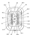
The another one that Fig. 4 illustrates in described three adjusting devices also is last adjusting device, two reinforcement 5.2.1,5.2.2 being connected with described adjusting device have also been shown, described beam firmly is connected with motor frame 7.2 on each side of adjusting motor 6.2 and adjusting device, in the figure, described side is hidden by a reinforcement 5.2.1.This adjusting device extends through pivoted member 43 in, pivoted member 43 is corresponding to foregoing element in being somebody's turn to do, be installed to be outside and rotate around interior axis of rotation 46 in the pivoted member 21, and outer pivoted member 21 is installed to be in described base conversely around outer axis of rotation 47 rotations.Yet interior pivoted member 43 comprises that first pivot window 45.1 and second pivot window 45.2, two reinforcement 5.2.1,5.2.2 extend through this first pivot window 45.1 and second pivot window 45.2 in parallel to each other separately.
Fig. 5 is the profile that position F5 obtains in the place in Fig. 4.In Fig. 5 illustration, screw 51 and its nut 52 screw-threaded engagement of adjusting device, this nut 52 is rigidly connected by the center waist 53 in nut shell 54 and the interior pivoted member 43, and described waist is formed by described two pivot windows 45.1,45.2 on each side of this waist.From this figure, can also see, each reinforcement 5.2.1,5.2.2 are by two inclined elements 55.1,55.2 be connected with interior pivoted member 43, one of them inclined element 55.1 is installed into, the screw 51 that centers on the adjusting device on interior pivoted member 43 1 sides is made banking motion, and another inclined element 55.2 is installed as by correspondence, and the screw 51 that centers on the described adjusting device on interior pivoted member 43 opposite sides is made banking motion.Each inclined element 55.1,55.2 is installed in the nut shell 54, so that carry out banking motion around the screw 51 of adjusting device.An inclined element comprises first base arm 56.1 and second base arm 56.2 that screw 51 diagonal angles of relative adjusting device are provided with, and its pedestal is directed in opposite direction, so that first base arm 56.1 supports one second sliding members 57.1 and first sliding members 57.2 that is connected with a reinforcement 5.2.1, and second base arm 56.2 supports one second sliding members 58.1 and first sliding members 58.2 that is connected with the second reinforcement 5.2.2.Correspondingly, second inclined element 55.2 on waist 53 opposite sides is formed and is orientated, and each reinforcement 5.2.1,5.2.2 will be as shown in Figure 5 be connected with inclined element 55.1,55.2 boths on waist 53 each side.Therefore, these two reinforcement 5.2.1,5.2.2 are connected with interior pivoted member 43 by described inclined element.
Fig. 6 a)-e) roughly illustrates the embodiment that falls into five kinds of different fundamental types in the scope of the invention.Run through Fig. 6, use with figure noted earlier in the corresponding Reference numeral of employed Reference numeral, this subgraph is represented the embodiment of the schematic fundamental type in the scope of the invention, wherein this machine comprises at least three adjusting devices 4.1,4.2,4.3, each adjusting device can be extended and shortened along its longitudinal direction, and wherein each adjusting device is connected with positioning head 11 by first joint 8,9,10.Each adjusting device 4.1,4.2,4.3 also is connected with base 2 by universal joint 3.1,3.2,3.3, and described positioning head 11 can move in working range according to the manipulation of adjusting device.At least two reinforcements 5.1,5.2 are connected with positioning head 11 by beam swivel bearing 100.1,100.2 separately, and each beam swivel bearing only has one degree of freedom, and promptly described bearing plays the function of hinge.Each reinforcement 5.1,5.2 also is arranged to along with one or more adjusting devices 4.1,4.2,4.3 are elongated or shortened, and laterally slides in the beam bearing 17.1,17.2 in base 2.As previously mentioned, each beam bearing 17.1,17.2 is connected with base 2 by beam universal joint BU1, BU2.Use shown in the four-headed arrow as Fig. 6 is a)-6e) middle, the beam bearing 17.2 of at least one reinforcement 5.2 also can be around the axis A rotation parallel with the longitudinal axis of reinforcement 5.2.
Fig. 6 a) illustrates the first fundamental type embodiment, first joint 8,9,10 of its middle regulator (for example first adjusting device 4.1) constitutes such joint, this joint directly links to each other with positioning head 11, and with the beam pivot journal 100.1 or the 100.2 spaced apart certain distances of reinforcement (for example first reinforcement 5.1), described axle journal also directly links to each other with positioning head 11.And the beam universal joint BU1 of first reinforcement 5.1 in the base 2 and beam bearing 17.1 are spaced apart with the universal joint 3.1,3.2,3.3 of adjusting device 4.1,4.2,4.3, and described universal joint and base 2 are rigidly connected.
Fig. 6 b) shown the embodiment of second fundamental type, first joint 8,9,10 of its middle regulator (for example first adjusting device 4.1) constitutes such joint, and this joint directly is connected with positioning head 11.In this embodiment, the beam swivel bearing 100.1 of reinforcement (for example first reinforcement 5.1) or 100.2 and this adjusting device be rigidly connected, but spaced apart with first joint 8,9,10 of this adjusting device.A) illustrated embodiment is corresponding with Fig. 6, and the beam universal joint BU1 of first reinforcement 5.1 in the base 2 and beam bearing 17.1 is spaced apart with the universal joint 3.1,3.2,3.3 of adjusting device 4.1,4.2,4.3, and the same and base 2 of described universal joint is rigidly connected.
Fig. 6 c) shown the embodiment of the 3rd fundamental type, first joint 8,9,10 of its middle regulator (for example first adjusting device 4.1) and reinforcement (for example first reinforcement 5.1) are rigidly connected.In this embodiment, the beam swivel bearing 100.1 of reinforcement 5.1 directly is connected with positioning head 11.Yet first joint 8,9,10 and the beam swivel bearing 100.1 of this adjusting device are spaced apart.With Fig. 6 a) and Fig. 6 b) illustrated embodiment is corresponding, the beam universal joint BU1 of the reinforcement 5.1 in the base 2 and beam bearing 17.1 are spaced apart with the universal joint 3.1,3.2,3.3 of adjusting device 4.1,4.2,4.3, described universal joint and base 2 are rigidly connected.
Fig. 6 d) shown the embodiment of the 4th fundamental type, the beam swivel bearing 100.1,100.2 of first joint 8,9,10 of its middle regulator (for example first adjusting device 4.1) and reinforcement (for example first reinforcement 5.1) constitutes and positioning head 11 direct-connected same joints.With Fig. 6 a), 6b) with 6c) illustrated embodiment is corresponding, the beam universal joint BU1 of first reinforcement 5.1 in the base 2 and beam bearing 17.1 are spaced apart with the universal joint 3.1,3.2,3.3 of adjusting device 4.1,4.2,4.3, and described universal joint and base 2 are rigidly connected.
Fig. 6 e) shown the embodiment of the 5th fundamental type, the beam swivel bearing 100.1,100.2 of first joint 8,9,10 of its middle regulator (for example first adjusting device 4.1) and reinforcement (for example first reinforcement 5.1) constitutes and positioning head 11 direct-connected same joints.The universal joint 3.1,3.2,3.3 and the base 2 of adjusting device 4.1,4.2,4.3 are rigidly connected, and are made of the beam universal joint of described reinforcement and the beam bearing in the base 2.Therefore, in this embodiment, this reinforcement moves with described adjusting device.
The embodiment of this 5th fundamental type as top with reference to Fig. 1-5 by introducing the embodiment that describes in detail, comprise the adjusting device that links to each other with reinforcement, this embodiment belongs to the embodiment of the 5th fundamental type.
Beam universal joint BU1 and BU2 are commonly referred to as universal joint (cardan joint), it has two frees degree, wherein the exercise performance of this joint makes the rotation of the anglec of rotation and interior axis of rotation 24 at outer axis of rotation 22 places owing to existing angle and different therebetween, and it is poor that this angle is commonly referred to the anglec of rotation.When the beam swivel bearing 100.1,100.2 that only has one degree of freedom is placed to square position each other, anglec of rotation difference about BU1 and BU2 cancels each other out, cause the motion locking of machine thus, unless allow at least one reinforcement rotation, shown in the following equation relevant with Fig. 7.
Anglec of rotation difference can be expressed as:

Wherein β is the angle between outer axis of rotation and the interior axis of rotation, and α 1 is the rotation of outer axis of rotation, and α 2 is rotations of interior axis of rotation.
Claims (22)
1. the machine of a parallel motion (1), it comprises at least three adjusting devices (4.1,4.2,4.3), each described adjusting device all can be elongated or shortened individually, each adjusting device (4.1 wherein, 4.2,4.3) and by one first joint (8,9,10) be connected with a positioning head (11), each adjusting device (4.1,4.2,4.3) is by a universal joint (3.1,3.2,3.3) be connected with base (2), and described positioning head (11) can be according to adjusting device (4.1,4.2,4.3) manipulation in working range, move, it is characterized in that:
The machine of described parallel motion further comprises: at least two reinforcements (5.1,5.2,5.2.1,5.2.2), wherein each all passed through corresponding beam swivel bearing (100.1,100.2) be connected with described positioning head (11), each beam swivel bearing only has one degree of freedom, wherein when one or more described adjusting devices (4.1,4.2,4.3) each reinforcement when being elongated or shortened (5.1,5.2,5.2.1,5.2.2) be suitable for beam bearing (17.1 at base (2), 17.2 17.2.1 laterally slides in 17.2.2), each beam bearing (17.1,17.2 17.2.1 is 17.2.2) by beam universal joint (BU1, BU2) be connected with base (2), and at least one reinforcement (5.2,5.2.1, beam bearing (17.2 5.2.2), 17.2.1,17.2.2) can around with described reinforcement (5.2,5.2.1, the rotation of axis that longitudinal axis 5.2.2) extends in parallel.
2. the machine of parallel motion according to claim 1 is characterized in that, at least one beam swivel bearing (100.1,100.2) is made of described first joint (8,9,10).
3. the machine of parallel motion according to claim 2 is characterized in that, (BU1 BU2) is made of a universal joint (3.1,3.2,3.3) at least one beam universal joint.
4. the machine of parallel motion according to claim 1 is characterized in that, and at least one reinforcement (5.1,5.2,5.2.1, beam swivel bearing (100.1,100.2) 5.2.2) is rigidly connected with adjusting device (4.1,4.2,4.3).
5. the machine of parallel motion according to claim 1 is characterized in that, (5.1,5.2,5.2.1's first joint (8,9,10) of at least one adjusting device (4.1,4.2,4.3) 5.2.2) is rigidly connected with reinforcement.
6. the machine of parallel motion according to claim 1, it is characterized in that, described universal joint (3.1,3.2,3.3) and beam universal joint (BU1, BU2) both comprises outer pivoted member (21), should be installed in the base (2) so that around outer axis of rotation (22 by outer pivoted member (21), 47) rotation, and have interior pivoted member (23,43), pivoted member (23 in described, 43) be installed in this outer pivoted member (21) so that around rotating with the rectangular interior axis of rotation (24,46) of this outer axis of rotation (22,47).
7. the machine of parallel motion according to claim 6 is characterized in that, described beam bearing (17.1,17.2) or with the interior pivoted member (23 of universal joint (3.1,3.2,3.3), 43) connect, perhaps (BU1, interior pivoted member BU2) connects with the beam universal joint.
8. the machine of parallel motion according to claim 1 is characterized in that, each reinforcement (5.1,5.2,5.2.1,5.2.2) on a first direction, have flexural rigidity, this flexural rigidity significantly greater than described reinforcement with the rectangular direction of described first direction on flexural rigidity.
9. the machine of parallel motion according to claim 8 is characterized in that, (5.1,5.2,5.2.1 5.2.2) has the shape of cross section of essentially rectangular to each reinforcement.
10. the machine of parallel motion according to claim 1, it is characterized in that described machine comprises three adjusting devices (4.1,4.2,4.3), each adjusting device is in the situation and reinforcement (5.1 that does not have any transition joint or bearing at described first joint (8,9,10), 5.2,5.2.1,5.2.2,5.3) be rigidly connected.
11. the machine of parallel motion according to claim 1 is characterized in that, (5.2.1's adjusting device (4.2) in the described adjusting device 5.2.2) is rigidly connected with the reinforcement that adds.
12. the machine of parallel motion according to claim 6 is characterized in that, the form of at least one adjusting device (4.1,4.2,4.3) is screw-nut body, and wherein screw or nut (28,52) are rigidly connected with interior pivoted member (23,43).
13. the machine of parallel motion according to claim 1 is characterized in that, the form of at least one adjusting device (4.1,4.2,4.3) is a linear motor.
14. the machine of parallel motion according to claim 13 is characterized in that, the part of described linear motor is made of reinforcement (5.1,5.2,5.2.1,5.2.2,5.3).
15. the machine of parallel motion according to claim 6 is characterized in that,
Each reinforcement (5.1,5.2,5.2.1,5.2.2,5.3) and comprise first sliding members (26,57.2 of the slide bar form of at least one longitudinal extension, 58.2), second sliding members of described first sliding members and guide rail form (27,57.1,58.1) connects in the shape mode, described second sliding members (27,57.1,58.1) connect with described interior pivoted member (23,43).
16. the machine of parallel motion according to claim 15 is characterized in that, described second sliding members (27,57.1,58.1) or fixedly connected with interior pivoted member (23,43) perhaps leads in the shape mode about pivoted member (23,43) in described.
17. the machine of parallel motion according to claim 12, it is characterized in that, the screw (31 of described screw-nut body, 51) be suitable at one end by adjusting device motor (6.1,6.2,6.3) drive, and the other end of described screw is supported by spring bearing (29), perhaps the nut of described screw-nut body (28,52) is suitable for being driven by adjusting device motor (6).
18. the machine of parallel motion according to claim 17 is characterized in that, described adjusting device motor (6.1,6.2,6.3) and be installed in motor frame (7.1,7.2,7.3) in, an end of described motor frame forms described first joint (8,9,10) parts (8), and described motor frame also has the surface of connection (15), and at least one reinforcement (5.1,5.2.1,5.2.2,5.3) be secured on the described connection surface.
19. the machine of parallel motion according to claim 1 is characterized in that, (5.1,5.2,5.2.1, described beam swivel bearing (100.1,100.2) 5.2.2) have and are oriented rectangular each other bearing axis at least two reinforcements.
20. the machine of parallel motion according to claim 12 is characterized in that, the described beam swivel bearing (100.1,100.3) of at least two reinforcements (5.1,5.3) has and is oriented bearing axis parallel to each other.
21. the machine of parallel motion according to claim 6 is characterized in that, (BU1, interior axis of rotation (24,46) BU3) is parallel with the bearing axis of each beam swivel bearing (100.1,100.3) for the described beam universal joint of two reinforcements (5.1,5.3).
22. the machine of parallel motion according to claim 21 is characterized in that, (BU1, interior axis of rotation (24) BU3) is parallel to each other for the described beam universal joint of two reinforcements (5.1,5.3).
Applications Claiming Priority (4)
| Application Number | Priority Date | Filing Date | Title |
|---|---|---|---|
| SE04028247 | 2004-11-18 | ||
| SE0402824A SE527873C2 (en) | 2004-11-18 | 2004-11-18 | Parallel kinematic machine |
| SE0402824-7 | 2004-11-18 | ||
| PCT/SE2005/001651 WO2006054935A1 (en) | 2004-11-18 | 2005-11-03 | Parallel-kinematical machine |
Publications (2)
| Publication Number | Publication Date |
|---|---|
| CN101155672A CN101155672A (en) | 2008-04-02 |
| CN101155672B true CN101155672B (en) | 2010-12-15 |
Family
ID=33516484
Family Applications (1)
| Application Number | Title | Priority Date | Filing Date |
|---|---|---|---|
| CN2005800395787A Expired - Fee Related CN101155672B (en) | 2004-11-18 | 2005-11-03 | Parallel-kinematical machine |
Country Status (22)
| Country | Link |
|---|---|
| US (1) | US8783127B2 (en) |
| EP (1) | EP1838501B1 (en) |
| JP (1) | JP4955568B2 (en) |
| KR (1) | KR101227727B1 (en) |
| CN (1) | CN101155672B (en) |
| AT (1) | ATE496737T1 (en) |
| AU (1) | AU2005307148B2 (en) |
| BR (1) | BRPI0518431B1 (en) |
| CA (1) | CA2587836C (en) |
| DE (1) | DE602005026175D1 (en) |
| DK (1) | DK1838501T3 (en) |
| ES (1) | ES2358240T3 (en) |
| IL (1) | IL183080A (en) |
| MX (1) | MX2007006036A (en) |
| MY (1) | MY141396A (en) |
| PL (1) | PL1838501T3 (en) |
| RU (1) | RU2395380C2 (en) |
| SE (1) | SE527873C2 (en) |
| SI (1) | SI1838501T1 (en) |
| TW (1) | TWI345520B (en) |
| WO (1) | WO2006054935A1 (en) |
| ZA (1) | ZA200705062B (en) |
Families Citing this family (33)
| Publication number | Priority date | Publication date | Assignee | Title |
|---|---|---|---|---|
| DE102006046758A1 (en) * | 2006-09-29 | 2008-04-03 | Abb Patent Gmbh | Arrangement, especially for positioning objects, has at least one pair of supports made up of two supports that run parallel one inside the other and together form parallelogram |
| KR101264800B1 (en) * | 2007-11-26 | 2013-05-15 | 모터 파워 컴파니 에스.알.엘. | A device for handling and/or performing work operations on objects |
| JP2012529920A (en) * | 2009-06-15 | 2012-11-29 | ディーエスエム アイピー アセッツ ビー.ブイ. | Hinge structure |
| SE535182C2 (en) * | 2010-06-17 | 2012-05-08 | Exechon Ab | A parallel kinematic machine with card holder |
| CN101954593B (en) * | 2010-09-07 | 2012-06-13 | 上海工程技术大学 | Triple rotating parallel mechanism for virtual axis machine tool and robot |
| CN101966502B (en) * | 2010-10-15 | 2012-12-12 | 江苏长虹汽车装备集团有限公司 | Vehicle painting hybrid rotor based on spatial and planar parallel mechanism with three degrees of freedom |
| CN102114599B (en) * | 2011-02-11 | 2012-08-08 | 上海工程技术大学 | Decoupling three-rotation parallel mechanism for imaginary axis lathe and robot |
| US9764464B2 (en) * | 2011-08-03 | 2017-09-19 | The Boeing Company | Robot including telescopic assemblies for positioning an end effector |
| CN102672714B (en) * | 2012-03-21 | 2014-05-21 | 天津大学 | High-rigidity high-precision five-coordinate parallel power head |
| CN102632394B (en) * | 2012-04-18 | 2013-12-11 | 浙江理工大学 | Three- DOF (degree of freedom) parallel mechanism with two vertical intersecting rotating shafts |
| KR101419897B1 (en) * | 2012-04-26 | 2014-07-15 | 고려대학교 산학협력단 | 5-dof micro robot of parallel-type |
| CN102699899B (en) * | 2012-06-06 | 2014-08-06 | 天津大学 | Highly over-constrained high-rigidity multi-coordinate hybrid robot |
| CN102699900B (en) * | 2012-06-06 | 2015-05-27 | 天津大学 | Over-constraint hybrid robot with double platforms and five degrees of freedom |
| CN102922507A (en) * | 2012-08-30 | 2013-02-13 | 南京理工大学 | Two-degree-of-freedom leveling device |
| KR101382666B1 (en) * | 2012-11-26 | 2014-04-07 | 양국진 | Parallel manipulator |
| US20140150593A1 (en) | 2012-12-05 | 2014-06-05 | Alio Industries, Inc. | Precision tripod motion system |
| CN103029122B (en) * | 2012-12-11 | 2015-03-11 | 北京交通大学 | Redundant-drive three-degree-of-freedom translation-type parallel-connection robot mechanism |
| CN103240614B (en) * | 2013-05-06 | 2015-11-25 | 江苏国威工程机械有限公司 | A kind of redundant drive five-axle linkage series-parallel machine tool |
| CN103252774B (en) * | 2013-05-07 | 2015-04-15 | 天津大学 | Space five-degree-of-freedom hybrid robot |
| WO2014185877A2 (en) * | 2013-05-13 | 2014-11-20 | Coşkunöz Metal Form Maki̇na Endüstri̇ Ve Ti̇c. A.Ş. | A laser processing machine with a movement mechanism |
| CN103600346A (en) * | 2013-11-25 | 2014-02-26 | 浙江理工大学 | Three-degree-of-freedom spatial orientation parallel mechanism |
| CN104384941B (en) * | 2014-09-16 | 2016-08-17 | 燕山大学 | There is the Planar Mechanisms parallel institution of equivalent Tricept mechanism kinematic |
| ES2540925B1 (en) | 2015-05-27 | 2016-01-22 | Caviaroli, S.L. | Encapsulation procedure of hydrophobic substances |
| CN105598478B (en) * | 2016-03-24 | 2018-10-12 | 江苏中智自动化有限公司 | A kind of high-precision numerical control machine parallel main shaft head |
| CN106378770B (en) * | 2016-11-09 | 2018-10-02 | 南京理工大学 | It is a kind of that two flat one turn of Three Degree Of Freedom robot mechanisms can be achieved |
| CN106426102B (en) * | 2016-11-09 | 2018-10-02 | 南京理工大学 | It is a kind of that there are three flat two turns of robot with five degrees of freedom mechanisms |
| CN108500953A (en) * | 2018-02-28 | 2018-09-07 | 上海大学 | A kind of five degree of freedom precision series-parallel robot containing moving platform additional constraint |
| CN108656092B (en) * | 2018-08-07 | 2020-11-27 | 燕山大学 | Series-parallel robot based on four branched chains, two-rotation and one-movement parallel mechanism |
| CN109128872B (en) * | 2018-09-26 | 2019-09-17 | 燕山大学 | A kind of symmetrical parallel three NC axes main tapping can be realized multi-direction Fixed-point Motion of A |
| CN110076444A (en) * | 2019-04-30 | 2019-08-02 | 天津大学 | A kind of two-freedom parallel connection head for Friction Stir Welding |
| CN110450142B (en) * | 2019-09-09 | 2024-08-20 | 哈工大机器人(合肥)国际创新研究院 | Six-degree-of-freedom parallel robot based on double gyroscope components |
| RU2744148C1 (en) * | 2019-12-16 | 2021-03-03 | Булат Азатович Еникеев | Machine with parallel kinematics of increased vibration resistance |
| CN113715003A (en) * | 2021-09-16 | 2021-11-30 | 江南大学 | RRP type two-rotation one-movement parallel mechanism with two non-coplanar rotating shafts |
Citations (4)
| Publication number | Priority date | Publication date | Assignee | Title |
|---|---|---|---|---|
| US4819496A (en) * | 1987-11-17 | 1989-04-11 | The United States Of America As Represented By The Secretary Of The Air Force | Six degrees of freedom micromanipulator |
| EP0925870A2 (en) * | 1997-12-24 | 1999-06-30 | Rolf Dipl.-Ing. Wissner | Device for positioning a first machine part relative to a second machine part |
| US6497548B1 (en) * | 1999-08-05 | 2002-12-24 | Shambhu Nath Roy | Parallel kinematics mechanism with a concentric sperical joint |
| CN1511674A (en) * | 2002-11-13 | 2004-07-14 | 德克尔・马霍普夫龙滕有限责任公司 | Machine tool |
Family Cites Families (16)
| Publication number | Priority date | Publication date | Assignee | Title |
|---|---|---|---|---|
| US148216A (en) | 1874-03-03 | Improvement in suspenders | ||
| US4407625A (en) * | 1981-05-15 | 1983-10-04 | Westinghouse Electric Corp. | Multi-arm robot |
| US4569627A (en) | 1983-03-10 | 1986-02-11 | Simunovic Sergio N | Robotic manipulator |
| GB2143498B (en) | 1983-07-21 | 1986-04-30 | Emi Ltd | Improvements in or relating to assembly robots |
| JPS60122711A (en) * | 1983-12-08 | 1985-07-01 | Oji Paper Co Ltd | Manufacture of porous carbon board |
| SE452279B (en) * | 1985-05-10 | 1987-11-23 | Neos Products Hb | ROBOT |
| EP0482268A1 (en) * | 1990-10-24 | 1992-04-29 | Marc Lecomte | Linear and translation guiding module |
| JP3192678B2 (en) * | 1991-04-30 | 2001-07-30 | キヤノン株式会社 | Z tilt arm |
| KR0160676B1 (en) * | 1995-02-20 | 1998-12-15 | 김광호 | Robot |
| JP3090257B2 (en) * | 1996-11-11 | 2000-09-18 | キタムラ機械株式会社 | Machining center |
| SE512338C2 (en) * | 1998-06-25 | 2000-02-28 | Neos Robotics Ab | System and method for controlling a robot |
| JP3731710B2 (en) * | 1998-10-01 | 2006-01-05 | ファナック株式会社 | Joint structure of parallel link mechanism |
| DE19952423A1 (en) * | 1999-10-30 | 2001-05-10 | Hueller Hille Gmbh | Processing machine for multi-axis movement of a tool or workpiece |
| FR2800659B1 (en) * | 1999-11-05 | 2002-01-18 | Process Conception Ing Sa | DEVICE FOR MOVING AN OBJECT SUBSTANTIALLY PARALLEL TO A PLANE |
| JP4249530B2 (en) * | 2003-04-11 | 2009-04-02 | 高松機械工業株式会社 | Positioning device using parallel mechanism |
| SE535182C2 (en) * | 2010-06-17 | 2012-05-08 | Exechon Ab | A parallel kinematic machine with card holder |
-
2004
- 2004-11-18 SE SE0402824A patent/SE527873C2/en not_active IP Right Cessation
-
2005
- 2005-10-24 TW TW094137069A patent/TWI345520B/en not_active IP Right Cessation
- 2005-11-03 KR KR1020077013693A patent/KR101227727B1/en active IP Right Grant
- 2005-11-03 DK DK05799561.5T patent/DK1838501T3/en active
- 2005-11-03 EP EP05799561A patent/EP1838501B1/en active Active
- 2005-11-03 PL PL05799561T patent/PL1838501T3/en unknown
- 2005-11-03 US US11/719,117 patent/US8783127B2/en active Active
- 2005-11-03 CN CN2005800395787A patent/CN101155672B/en not_active Expired - Fee Related
- 2005-11-03 JP JP2007542969A patent/JP4955568B2/en not_active Expired - Fee Related
- 2005-11-03 ES ES05799561T patent/ES2358240T3/en active Active
- 2005-11-03 WO PCT/SE2005/001651 patent/WO2006054935A1/en active Application Filing
- 2005-11-03 AT AT05799561T patent/ATE496737T1/en active
- 2005-11-03 MX MX2007006036A patent/MX2007006036A/en active IP Right Grant
- 2005-11-03 AU AU2005307148A patent/AU2005307148B2/en not_active Ceased
- 2005-11-03 BR BRPI0518431A patent/BRPI0518431B1/en not_active IP Right Cessation
- 2005-11-03 CA CA2587836A patent/CA2587836C/en active Active
- 2005-11-03 SI SI200531228T patent/SI1838501T1/en unknown
- 2005-11-03 DE DE602005026175T patent/DE602005026175D1/en active Active
- 2005-11-03 RU RU2007120945/02A patent/RU2395380C2/en active
- 2005-11-07 MY MYPI20055214A patent/MY141396A/en unknown
-
2007
- 2007-05-09 IL IL183080A patent/IL183080A/en active IP Right Grant
- 2007-06-11 ZA ZA200705062A patent/ZA200705062B/en unknown
Patent Citations (4)
| Publication number | Priority date | Publication date | Assignee | Title |
|---|---|---|---|---|
| US4819496A (en) * | 1987-11-17 | 1989-04-11 | The United States Of America As Represented By The Secretary Of The Air Force | Six degrees of freedom micromanipulator |
| EP0925870A2 (en) * | 1997-12-24 | 1999-06-30 | Rolf Dipl.-Ing. Wissner | Device for positioning a first machine part relative to a second machine part |
| US6497548B1 (en) * | 1999-08-05 | 2002-12-24 | Shambhu Nath Roy | Parallel kinematics mechanism with a concentric sperical joint |
| CN1511674A (en) * | 2002-11-13 | 2004-07-14 | 德克尔・马霍普夫龙滕有限责任公司 | Machine tool |
Also Published As
Similar Documents
| Publication | Publication Date | Title |
|---|---|---|
| CN101155672B (en) | Parallel-kinematical machine | |
| AU2011265794B2 (en) | A parallel-kinematical machine with gimbal holders | |
| US20060241810A1 (en) | High stiffness, high accuracy, parallel kinematic, three degree of freedom motion platform | |
| JP4381812B2 (en) | Flexible track positioning machine | |
| JP3743835B2 (en) | Remote elastic central equipment | |
| US7163247B2 (en) | Tool holder | |
| JP3905456B2 (en) | Compound loading test equipment | |
| CN106799728A (en) | A kind of passive compliance device | |
| CN106734420A (en) | A kind of space pipe fitting flexible bending reverses building mortion | |
| EP2509754A1 (en) | Connecting device for the connection of sections/girders/arms to an attachment | |
| CN221498222U (en) | Crawler angle adjusting mechanism of double-crawler wall climbing robot | |
| CN218151774U (en) | Hydraulic actuating system | |
| US20230173659A1 (en) | Compliant Mechanism for Improving Reaction Torque Sensing in Robotic Actuators | |
| DE19846355A1 (en) | Universal joint for use in automobiles has crosspiece with overlapping spigots and supports tension and pressure by means of additional support spigot pairs | |
| Talken et al. | Approximating Hinges With Multimaterial Compliant Joints | |
| KR20240112582A (en) | Passive compensation mechanism for high load |
Legal Events
| Date | Code | Title | Description |
|---|---|---|---|
| C06 | Publication | ||
| PB01 | Publication | ||
| C10 | Entry into substantive examination | ||
| SE01 | Entry into force of request for substantive examination | ||
| C14 | Grant of patent or utility model | ||
| GR01 | Patent grant | ||
| C41 | Transfer of patent application or patent right or utility model | ||
| TR01 | Transfer of patent right |
Effective date of registration: 20160321 Address after: Sweden Sollentuna Patentee after: Love Xichong grams of Technology Holding Co. Address before: Sweden Sollentuna Patentee before: Eexchon AB |
|
| CF01 | Termination of patent right due to non-payment of annual fee |
Granted publication date: 20101215 |