CN101087638A - Circumferentially pleated filter assembly and method of making the same - Google Patents
Circumferentially pleated filter assembly and method of making the same Download PDFInfo
- Publication number
- CN101087638A CN101087638A CNA2005800397316A CN200580039731A CN101087638A CN 101087638 A CN101087638 A CN 101087638A CN A2005800397316 A CNA2005800397316 A CN A2005800397316A CN 200580039731 A CN200580039731 A CN 200580039731A CN 101087638 A CN101087638 A CN 101087638A
- Authority
- CN
- China
- Prior art keywords
- fold
- filter
- filter sleeve
- sleeve
- filter element
- Prior art date
- Legal status (The legal status is an assumption and is not a legal conclusion. Google has not performed a legal analysis and makes no representation as to the accuracy of the status listed.)
- Pending
Links
- 238000004519 manufacturing process Methods 0.000 title description 4
- 238000000034 method Methods 0.000 claims abstract description 18
- 230000000712 assembly Effects 0.000 claims description 66
- 238000000429 assembly Methods 0.000 claims description 66
- 238000001914 filtration Methods 0.000 claims description 46
- 239000012530 fluid Substances 0.000 claims description 36
- 239000000463 material Substances 0.000 claims description 26
- 150000001875 compounds Chemical class 0.000 claims description 25
- 238000007789 sealing Methods 0.000 claims description 19
- 238000011144 upstream manufacturing Methods 0.000 claims description 15
- 230000015572 biosynthetic process Effects 0.000 claims description 14
- 238000006116 polymerization reaction Methods 0.000 claims description 8
- 230000002093 peripheral effect Effects 0.000 claims description 6
- 239000011248 coating agent Substances 0.000 claims description 4
- 238000000576 coating method Methods 0.000 claims description 4
- 239000007921 spray Substances 0.000 claims description 4
- 230000004888 barrier function Effects 0.000 claims description 3
- 239000004745 nonwoven fabric Substances 0.000 claims description 3
- 238000002360 preparation method Methods 0.000 claims 10
- 238000010276 construction Methods 0.000 claims 3
- 238000001467 acupuncture Methods 0.000 claims 1
- 239000011152 fibreglass Substances 0.000 claims 1
- 239000002131 composite material Substances 0.000 description 10
- 239000004743 Polypropylene Substances 0.000 description 4
- 230000014509 gene expression Effects 0.000 description 4
- -1 polypropylene Polymers 0.000 description 4
- 229920001155 polypropylene Polymers 0.000 description 4
- 230000002950 deficient Effects 0.000 description 3
- 239000000155 melt Substances 0.000 description 3
- 230000003321 amplification Effects 0.000 description 2
- 238000013461 design Methods 0.000 description 2
- 238000005516 engineering process Methods 0.000 description 2
- 239000000835 fiber Substances 0.000 description 2
- 239000004811 fluoropolymer Substances 0.000 description 2
- 229920002313 fluoropolymer Polymers 0.000 description 2
- 239000003365 glass fiber Substances 0.000 description 2
- 238000003199 nucleic acid amplification method Methods 0.000 description 2
- 238000012856 packing Methods 0.000 description 2
- 238000003466 welding Methods 0.000 description 2
- 229920000784 Nomex Polymers 0.000 description 1
- 230000004323 axial length Effects 0.000 description 1
- 229920001971 elastomer Polymers 0.000 description 1
- 239000000806 elastomer Substances 0.000 description 1
- 238000004880 explosion Methods 0.000 description 1
- 230000006872 improvement Effects 0.000 description 1
- 230000003993 interaction Effects 0.000 description 1
- 239000007788 liquid Substances 0.000 description 1
- 239000012528 membrane Substances 0.000 description 1
- 239000002184 metal Substances 0.000 description 1
- 238000012986 modification Methods 0.000 description 1
- 230000004048 modification Effects 0.000 description 1
- 239000005445 natural material Substances 0.000 description 1
- 239000004763 nomex Substances 0.000 description 1
- 239000004033 plastic Substances 0.000 description 1
- 229920003023 plastic Polymers 0.000 description 1
- 239000011148 porous material Substances 0.000 description 1
- 230000008569 process Effects 0.000 description 1
- 238000012797 qualification Methods 0.000 description 1
- 229920001059 synthetic polymer Polymers 0.000 description 1
- 230000017105 transposition Effects 0.000 description 1
Images


Classifications
-
- B—PERFORMING OPERATIONS; TRANSPORTING
- B01—PHYSICAL OR CHEMICAL PROCESSES OR APPARATUS IN GENERAL
- B01D—SEPARATION
- B01D29/00—Filters with filtering elements stationary during filtration, e.g. pressure or suction filters, not covered by groups B01D24/00 - B01D27/00; Filtering elements therefor
- B01D29/11—Filters with filtering elements stationary during filtration, e.g. pressure or suction filters, not covered by groups B01D24/00 - B01D27/00; Filtering elements therefor with bag, cage, hose, tube, sleeve or like filtering elements
- B01D29/111—Making filtering elements
-
- B—PERFORMING OPERATIONS; TRANSPORTING
- B01—PHYSICAL OR CHEMICAL PROCESSES OR APPARATUS IN GENERAL
- B01D—SEPARATION
- B01D29/00—Filters with filtering elements stationary during filtration, e.g. pressure or suction filters, not covered by groups B01D24/00 - B01D27/00; Filtering elements therefor
- B01D29/11—Filters with filtering elements stationary during filtration, e.g. pressure or suction filters, not covered by groups B01D24/00 - B01D27/00; Filtering elements therefor with bag, cage, hose, tube, sleeve or like filtering elements
- B01D29/13—Supported filter elements
- B01D29/15—Supported filter elements arranged for inward flow filtration
- B01D29/21—Supported filter elements arranged for inward flow filtration with corrugated, folded or wound sheets
-
- B—PERFORMING OPERATIONS; TRANSPORTING
- B01—PHYSICAL OR CHEMICAL PROCESSES OR APPARATUS IN GENERAL
- B01D—SEPARATION
- B01D29/00—Filters with filtering elements stationary during filtration, e.g. pressure or suction filters, not covered by groups B01D24/00 - B01D27/00; Filtering elements therefor
- B01D29/11—Filters with filtering elements stationary during filtration, e.g. pressure or suction filters, not covered by groups B01D24/00 - B01D27/00; Filtering elements therefor with bag, cage, hose, tube, sleeve or like filtering elements
- B01D29/13—Supported filter elements
- B01D29/23—Supported filter elements arranged for outward flow filtration
- B01D29/232—Supported filter elements arranged for outward flow filtration with corrugated, folded or wound sheets
-
- B—PERFORMING OPERATIONS; TRANSPORTING
- B01—PHYSICAL OR CHEMICAL PROCESSES OR APPARATUS IN GENERAL
- B01D—SEPARATION
- B01D29/00—Filters with filtering elements stationary during filtration, e.g. pressure or suction filters, not covered by groups B01D24/00 - B01D27/00; Filtering elements therefor
- B01D29/50—Filters with filtering elements stationary during filtration, e.g. pressure or suction filters, not covered by groups B01D24/00 - B01D27/00; Filtering elements therefor with multiple filtering elements, characterised by their mutual disposition
- B01D29/52—Filters with filtering elements stationary during filtration, e.g. pressure or suction filters, not covered by groups B01D24/00 - B01D27/00; Filtering elements therefor with multiple filtering elements, characterised by their mutual disposition in parallel connection
- B01D29/54—Filters with filtering elements stationary during filtration, e.g. pressure or suction filters, not covered by groups B01D24/00 - B01D27/00; Filtering elements therefor with multiple filtering elements, characterised by their mutual disposition in parallel connection arranged concentrically or coaxially
-
- B—PERFORMING OPERATIONS; TRANSPORTING
- B01—PHYSICAL OR CHEMICAL PROCESSES OR APPARATUS IN GENERAL
- B01D—SEPARATION
- B01D2201/00—Details relating to filtering apparatus
- B01D2201/12—Pleated filters
- B01D2201/122—Pleated filters with pleats of different length
-
- Y—GENERAL TAGGING OF NEW TECHNOLOGICAL DEVELOPMENTS; GENERAL TAGGING OF CROSS-SECTIONAL TECHNOLOGIES SPANNING OVER SEVERAL SECTIONS OF THE IPC; TECHNICAL SUBJECTS COVERED BY FORMER USPC CROSS-REFERENCE ART COLLECTIONS [XRACs] AND DIGESTS
- Y10—TECHNICAL SUBJECTS COVERED BY FORMER USPC
- Y10T—TECHNICAL SUBJECTS COVERED BY FORMER US CLASSIFICATION
- Y10T156/00—Adhesive bonding and miscellaneous chemical manufacture
- Y10T156/10—Methods of surface bonding and/or assembly therefor
- Y10T156/1002—Methods of surface bonding and/or assembly therefor with permanent bending or reshaping or surface deformation of self sustaining lamina
- Y10T156/1025—Methods of surface bonding and/or assembly therefor with permanent bending or reshaping or surface deformation of self sustaining lamina to form undulated to corrugated sheet and securing to base with parts of shaped areas out of contact
-
- Y—GENERAL TAGGING OF NEW TECHNOLOGICAL DEVELOPMENTS; GENERAL TAGGING OF CROSS-SECTIONAL TECHNOLOGIES SPANNING OVER SEVERAL SECTIONS OF THE IPC; TECHNICAL SUBJECTS COVERED BY FORMER USPC CROSS-REFERENCE ART COLLECTIONS [XRACs] AND DIGESTS
- Y10—TECHNICAL SUBJECTS COVERED BY FORMER USPC
- Y10T—TECHNICAL SUBJECTS COVERED BY FORMER US CLASSIFICATION
- Y10T156/00—Adhesive bonding and miscellaneous chemical manufacture
- Y10T156/10—Methods of surface bonding and/or assembly therefor
- Y10T156/1002—Methods of surface bonding and/or assembly therefor with permanent bending or reshaping or surface deformation of self sustaining lamina
- Y10T156/1036—Bending of one piece blank and joining edges to form article
- Y10T156/1038—Hollow cylinder article
-
- Y—GENERAL TAGGING OF NEW TECHNOLOGICAL DEVELOPMENTS; GENERAL TAGGING OF CROSS-SECTIONAL TECHNOLOGIES SPANNING OVER SEVERAL SECTIONS OF THE IPC; TECHNICAL SUBJECTS COVERED BY FORMER USPC CROSS-REFERENCE ART COLLECTIONS [XRACs] AND DIGESTS
- Y10—TECHNICAL SUBJECTS COVERED BY FORMER USPC
- Y10T—TECHNICAL SUBJECTS COVERED BY FORMER US CLASSIFICATION
- Y10T156/00—Adhesive bonding and miscellaneous chemical manufacture
- Y10T156/10—Methods of surface bonding and/or assembly therefor
- Y10T156/1002—Methods of surface bonding and/or assembly therefor with permanent bending or reshaping or surface deformation of self sustaining lamina
- Y10T156/1051—Methods of surface bonding and/or assembly therefor with permanent bending or reshaping or surface deformation of self sustaining lamina by folding
Landscapes
- Chemical & Material Sciences (AREA)
- Chemical Kinetics & Catalysis (AREA)
- Filtering Of Dispersed Particles In Gases (AREA)
- Filtering Materials (AREA)
- Lubrication Details And Ventilation Of Internal Combustion Engines (AREA)
Abstract
A filter assembly is provided which includes an outer filter sleeve formed at least in part by a plurality of pleats, an inner filter sleeve formed at least in part by a plurality of pleats, wherein the inner and outer filter sleeves define a passage therebetween. An inlet cap is secured to a first end of the inner and outer filter sleeves and it has at least one inlet port communicating with the passage, and an end cap is secured to a second end of the inner and outer filter sleeves and it has an end surface closing the passage. Methods of forming such a filter assembly are also provided.
Description
Technical field
The present invention relates to the filtering flow field, more particularly, the present invention relates to a kind of bag type filtering assembly, between these two medium sleeves, limit the circular passage that receives fluid to be filtered with two concentric circumferentially pleated formula medium sleeves.
Background technology
The bag type filtering system that is used to filter fluid is well-known in this area.These filtration systems generally include cylinder blanket, and end sealing and its opposite end of this shell have removable cap.Inflow pipe is transported to fluid to be filtered in the shell, has filtered fluid and has flowed out from shell by effuser.
Removable bag filter is arranged on enclosure, so that filter the fluid that is transported to filter.Usually, bag filter comprises the filter medium with open upper and closed bottom end.Filter bag is supported on unlimited basket or guard inside, and basket or guard are suspended on enclosure usually.Basket is used to support the medium of filter bag, so that prevent medium explosion when liquid is filled filter bag.
There are several defectives in existing bag filter.A defective is that filter bag has bigger hold-up volume.Therefore, it is very difficult to take out the filter bag of using, and this is because filter bag is heavier relatively.The filter bag that is full of will weigh 30 pounds, and its inside may accommodate the material of harm, and this has increased the difficulty of taking out.In order to remedy this situation, before taking out the filter bag of using, use the emptying air bag to reduce its hold-up volume.Yet these air bags usually are inconvenient to operate.
Another defective relevant with existing bag filter is that the effective filtration area that they provide is limited.Because the industrial standardization of basket size is restricted so increase the trial of the effective filtration area of existing bag filter.That is to say that the filter bag that can obtain has two remarkable different sizes usually: (#1) 7 " diameter * 16 " length; And (#2) 7 " diameter * 32 " length.As a result, any increase of effective filtration area all is subjected to changing the restriction of the requirement of filter external diameter.
At the design bag filter so that hold-up volume is minimum and make effective filtration area carry out a large amount of trials aspect maximum.For instance, U.S. Patent No. 4,081,379 have disclosed a kind of annular filter bag, and it provides the useable surface area bigger than conventional filter bag.U.S. Patent No. 4,863,602 and 4,877,526 have disclosed a kind of filter bag with surface area of increase, and it comprises the clad of the melt blown media of a plurality of packings, and is provided with flexible support layers between each layer.Hayward Lofclear 500 serial bag filters provide the surface area that increases by folding pre-filtering layer by final filter course packing.These effort of the prior art mostly do not reach target.
In U.S. Patent No. 6,030, disclosed a kind of useful especially bag type filtering assembly in 531 and 6,238,560.In this unique filter assemblies, by being provided, two concentric medium sleeves increased effective surface area, and these two medium sleeves at one end are connected on the unlimited inlet cover, and are connected in the opposite end on the end cap of sealing.The hold-up volume of staying the fluid in the filter element after two sleeve structures also make and use minimizes, thereby makes the easier filter element that takes out from filter basket/shell.
For many years, the design of cylindrical fold formula filter cylinder attempts making the quantity maximization of the filter medium that can be engaged in the filter cylinder with given external diameter or surface area too.In the radially fold formula filter cylinder of standard, can be around the fold restricted number of filter cylinder core body filling the quantity of the filter medium that can clog in the filter cylinder.As a result, between the adjacent pleats of the periphery of filter element, there is a large amount of free spaces.
The similarity of spirality pleated filter element and standard radial pleated filter element is that it comprises a plurality of vertical folds that are provided with cylindrical structure.Yet in the spirality pleated filter, roll the end of fold, so that minimize near the interval between the adjacent pleats face of filter element outer radius.In this case, the fold highly significant is greater than the distance between the interior week of the periphery of filter cylinder core body and filter cylinder box.As a result, in the spirality pleated filter, the fold of periphery has occupied the unnecessary volume that is usually expressed as free space in pleated filter element radially.This provides the filter table area that increases than standard radial fold building.
It will be useful that the technology that will be used to improve the effective surface area of fold formula filter cylinder is applied to bag filter.This will provide the filter life of increase, lower pressure drop and provide lower running cost for the consumer.
Summary of the invention
The present invention relates to a kind of useful novel pocket type filter assemblies, it comprises: outside filter sleeve, and it forms to the fold of small part by a plurality of longitudinal extensions; And inboard filter sleeve, it forms to the fold of small part by a plurality of longitudinal extensions.Compare with conventional bag filter commonly known in the art, this concentric pleated filter sleeve enlarges markedly the effective surface area of filter assemblies of the present invention.The surface area that increases will prolong the life-span of filter, reduce pressure drop and reduce consumer's running cost.Limit annular fluid passage between concentric medial and lateral filter sleeve, compare with conventional bag filter commonly known in the art, this fluid passage has the hold-up volume that reduces.This hold-up volume reduce to make that exceeding its probable life at filter takes out filter assemblies after the time limit easily from shell.
Inlet cover is fixed on first end of medial and lateral filter sleeve, and has the inlet that at least one is communicated with the fluid passage of filter assemblies.End cap is fixed on second end of medial and lateral filter sleeve, and the end face with closed fluid passages.In presently preferred embodiment of the present invention, sheath surrounds the downstream of outside filter sleeve, so that level and smooth and continuous surface to be provided, takes out thereby protection filter medium and help are installed on outside filter sleeve in the basket and from basket.The material of rarer porosity forms sheath by have relatively such as polymeric web or sieve etc.Can expect that in addition available similar sheath surrounds or otherwise protect the downstream of inboard filter sleeve, with further help inboard filter sleeve is installed in the basket and from basket and take out.
Preferably, each filter sleeve comprises a plurality of longitudinal extensions and the kyrtom that circumferentially is provided with.In one embodiment of the invention, the kyrtom of the circumferential setting of the adjacency of arbitrary or two filter sleeves about 50% to 80% of fold arc length or the arch height of overlapping each other.In one embodiment of the invention, the kyrtom of the circumferential setting of the adjacency of arbitrary or two filter sleeves is circumferentially spaced apart each other.In one embodiment of the invention, the kyrtom of the circumferential setting of arbitrary or two filter sleeves evenly distributes.In one embodiment of the invention, the kyrtom of the circumferential setting of arbitrary or two filter sleeves has equal arc length.In one embodiment of the invention, the circumferential kyrtom that is provided with of each of medial and lateral filter sleeve has radial outside fold supporting leg and radially inner side fold supporting leg.Usually, the arc length of radially inner side fold supporting leg or arch height are shorter than the arc length or the arch height of radial outside fold supporting leg.
Preferably, the medial and lateral filter sleeve is all formed by the multilayered fold compound, and this compound comprises at least one filtering medium layer, upstream support/drainage layer and downstream support/drainage layer.Preferably, filter medium is selected from the group of following filtering material, but this group comprises any flexibility and fold filter medium, and such as melt blown media, felt paper, wet method paper (glass fibre), preferred medium is selected from and melts and sprays filter medium and microporous barrier.According to the applied occasion of filter, can also use other filtering material.
In one embodiment of the invention, layered composite comprises a plurality of filtering medium layers with same porosity.In another embodiment of the present invention, layered composite comprises a plurality of filtering medium layers with different porosities.Preferably, the support of layered composite/drainage layer is made of the material that is selected from following group, and this group comprises extruding polymerization net or net and polymerization non-woven fabric (that is, spunbond etc.).According to the applied occasion of filter, can also use other support/drainage material.
According to one embodiment of present invention, inlet cover is combined on outside filter sleeve and the inboard filter sleeve, and elastomeric seal can be molded on the periphery of inlet cover.End cap also is combined on outside filter sleeve and the inboard filter sleeve.Preferably, inboard filter sleeve limits the centre bore of filter assemblies, and end cap comprises the central outlet that is communicated with centre bore.
In one embodiment of the invention, at least one is attached on the side of inlet cover and end cap in the filter sleeve of medial and lateral.In another embodiment of the present invention, at least one is attached on the end face of inlet cover and end cap in the filter sleeve of medial and lateral.
The invention still further relates to a kind of like this filter assemblies, this filter assemblies comprises: the radial outside filter sleeve, and its multilayered fold compound by the kyrtom that comprises a plurality of longitudinal extensions and circumferentially be provided with forms; And the radially inner side filter sleeve, itself and radial outside filter sleeve are arranged with one heart, and are formed by the multilayered fold compound of the kyrtom that comprises a plurality of longitudinal extensions and circumferentially be provided with.Inboard filter sleeve limits centre bore, limits the circular passage between the filter sleeve of medial and lateral.Inlet cover is incorporated into the upper end of medial and lateral filter sleeve, and has the inlet that at least one is communicated with the circular passage.End cap is incorporated into the lower end of medial and lateral filter sleeve, and has the end face of closed ring passage and the central outlet that is communicated with centre bore.In addition, the sheath of porous material surrounds the radial outside filter sleeve.Similarly sheath can also surround the inner surface of radially inner side filter sleeve.
The invention still further relates to a kind of filtration system, comprising: shell or pressure vessel, it has the detachable lid of inner chamber and closed inner chamber.Inflow pipe is transported to unfiltered fluid in the inner chamber of shell, and effuser is carried the fluid of filtration that flows out from the inner chamber of shell.This system also comprises: filter element, and it is arranged in the inner chamber of shell, and comprises the radially inner side filter sleeve and the radial outside filter sleeve of arranged concentric, and each filter sleeve has the kyrtom of a plurality of circumferential arrangement.Limit the circular passage between the filter sleeve of medial and lateral, be used to receive the unfiltered fluid from the inflow pipe of shell, inboard filter sleeve limits the centre bore that is communicated with the effuser of shell.
Inlet cover is fixed on the upper end of medial and lateral filter sleeve, and a plurality of inlets are communicated with the circular passage; End cap is fixed on the lower end of medial and lateral filter sleeve, and central outlet is communicated with centre bore.Preferably, inlet cover comprises the peripheral sealing surface that coating is molded, and the sealing face is used in the lid sealed engagement of shell back with shell that filter assemblies is packed into.In addition, this filtration system comprises the porose basket that is used to support the filter assemblies in the shell.
The invention still further relates to a kind of method that forms filter element, comprise the steps: to prepare a plurality of setting folds that have the first fold supporting leg and the second fold supporting leg separately, wherein, the first fold supporting leg of a fold partly is connected by middle fold with the second fold supporting leg of last fold; To erect fold and move to overlap condition, wherein, pleated portions is divided into the part of the second fold supporting leg of last fold in the middle of each; And overlapping fold shape become cylindrical structure.The step for preparing a plurality of setting folds comprises: form a plurality of setting folds, it has the first contour fold supporting leg and the second fold supporting leg, perhaps have the first highly different fold supporting legs and the second fold supporting leg, wherein the height of the first fold supporting leg is less than the height of the second fold supporting leg.
The step for preparing a plurality of setting folds comprises: adopt the middle fold that comprises at least one middle fold section partly the first fold supporting leg of a fold to be connected with the second fold supporting leg of last fold.Fold section in the middle of the fold part can comprise two in the middle of described.Fold section can have identical length in the middle of these, perhaps can have different length.Preferably, the length of middle fold part is less than the height of last fold supporting leg, and more preferably, the length of middle fold part is about half of height of last fold supporting leg.
In conjunction with regarding to detailed description of the present invention under the following accompanying drawing reading, those of ordinary skill in the art can more easily understand the above-mentioned and others of bag type filtering assembly of the present invention.
Description of drawings
How to make and use filter assemblies of the present invention for those skilled in the art can more easily be understood, describe presently preferred embodiment of the present invention below with reference to the accompanying drawings in detail, wherein:
Fig. 1 is the perspective view of the filter assemblies that presently preferred embodiment constitutes according to the present invention, wherein, the part of the sheath of encirclement filter element is cut, so that show the inboard and the external circumferential pleated filter sleeve that form filter element, the pleated filter sleeve is partly dissectd, so that show its fold building and be defined in fluid passage between the sleeve;
Figure 1A is the local enlarged perspective of pleated filter sleeve shown in Figure 1, wherein, separates the section of the fold of each sleeve, so that upstream support/drainage layer, downstream support/drainage layer and a plurality of dielectric layer that forms the fold compound is shown;
Fig. 2 is the top view of filter assemblies shown in Figure 1, the architectural feature of the inlet cover of the upper end that is arranged on filter assemblies is shown, this inlet cover comprises a plurality of circumferentially isolated arc inlets, and these inlets allow fluid to flow into the fluid passage that is defined between the pleated filter sleeve;
Fig. 2 A is the fragmentary, perspective view of filter assemblies of the present invention, compares with unlimited inlet cover shown in Figure 2, and this filter assemblies comprises the inlet cover of sealing;
Fig. 3 is the bottom view of filter assemblies shown in Figure 1, and the architectural feature of the end cap of the lower end that is arranged on filter assemblies is shown, and this end cap comprises annular end face, and this annular end face sealing is defined in the fluid passage between the pleated filter sleeve;
Fig. 4 is the local amplification end view of filter assemblies, wherein, the part of end cap is cut, so that show the fold building of inboard filter sleeve, the adjacent segmental fold of the circumferential setting of inboard and outside filter sleeve abuts each other, and therefore the base portion of adjacent pleats is followed at the top of a fold;
Fig. 5 is the local amplification end view of filter assemblies, and wherein, the part of end cap is cut, so that show the fold building of inboard filter sleeve, the adjacent segmental fold of the circumferential setting of inboard and outside filter sleeve is overlapped each other;
Fig. 6 is the cross-sectional view of the part of inlet cover shown in Figure 2, and the line 6-6 intercepting of this figure in Fig. 2 illustrates the inboard of filter element and outside sleeve and be fixed on mode on the inlet cover;
Fig. 7 is the cross-sectional view of the part of end cap shown in Figure 3, and the line 7-7 intercepting of this figure in Fig. 3 illustrates the inboard of filter element and outside sleeve and be fixed on mode on the end cap;
Fig. 8 is arranged on the cross-sectional view of the filter assemblies of the present invention in the pressure vessel, and wherein a series of arrows are represented the direction stream by the fluid of filter assemblies;
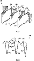
Fig. 9 is the perspective view that is used to form circumferentially pleated pleated structure of the present invention, this pleated structure comprises having the first contour fold supporting leg and the setting fold of the second fold supporting leg, wherein, the first fold supporting leg of a fold partly is connected by flat middle fold with the second fold supporting leg of last fold;
Figure 10 is the top view of pleated structure shown in Figure 9;
Figure 11 moves to the circumferentially pleated perspective view that overlap condition forms by the pleated structure with Fig. 9 and Figure 10, and wherein, pleated portions is divided into the part of the second fold supporting leg of last fold in the middle of each;
Figure 12 is the perspective view that is used to form circumferentially pleated another kind of pleated structure of the present invention, this pleated structure comprises having the first contour fold supporting leg and the setting fold of the second fold supporting leg, wherein, the first fold supporting leg of a fold partly is connected by middle fold with the second fold supporting leg of last fold, and middle pleated portions branch comprises two isometric middle fold sections;
Figure 13 is the top view of pleated structure shown in Figure 12;
Figure 14 moves to the circumferentially pleated perspective view that overlap condition forms by the pleated structure with Figure 12 and Figure 13, and wherein, two isometric middle fold sections flatten and become the part of the second fold supporting leg of last fold;
Figure 15 is a circumferentially pleated top view shown in Figure 14;
Figure 16 is the perspective view that is used to form circumferentially pleated another kind of pleated structure of the present invention, this pleated structure comprises the first fold supporting leg with differing heights and the setting fold of the second fold supporting leg, wherein, the first fold supporting leg of a fold partly is connected by middle fold with the second fold supporting leg of last fold, and middle pleated portions branch comprises the middle fold section of two different lengths;
Figure 17 is the top view of pleated structure shown in Figure 16; And
Figure 18 moves to the circumferentially pleated perspective view that overlap condition forms by the pleated structure with Figure 16 and Figure 17, and wherein, the middle fold section of two different lengths flattens and becomes the part of the second fold supporting leg of last fold.
The specific embodiment
With reference now to accompanying drawing,, wherein identical Reference numeral is represented similar structural element of the present invention and/or feature, the filter assemblies that presently preferred embodiment constitutes according to the present invention shown in Fig. 1, and it is generally by Reference numeral 10 expressions.Filter assemblies 10 is for being commonly referred to a kind of filter assemblies of bag filter, and it is collapsible and easy disposal after using preferably.
With reference to figure 1, filter assemblies 10 comprises the inboard filter sleeve 12 of substantially cylindrical and the outside filter sleeve 14 of substantially cylindrical.Medial and lateral filter sleeve 12,14 all forms to the kyrtom 16 of small part by a plurality of longitudinal extensions and circumferentially setting, and the back will be described this in more detail.Fold 16 is used for increasing with respect to the bag filter of prior art the quantity of effective filtration area in the filter assemblies.Effective filtration area is meant the quantity of the filter medium that fluid in use can touch.Between medial and lateral filter sleeve 12,14, be defined for the elongated circular passage 18 that holds unfiltered fluid, the centre bore 20 that is used to carry fluid of inboard filter sleeve 12 limiting filter assemblies 10.
With reference to figure 2, inlet cover 22 is preferably by constituting such as high strength light plastics such as polypropylene.In order to be easy to assembling, inlet cover 22 is made of two different structural details, promptly inboard body part 22a and outboard flanges part 22b.The inboard body part 22a of inlet cover 22 limits the annular end face 25 of impermeability, and this annular end face limits center access port 23.The size of access port 23 and structure are made and can be held inflow pipe, and this inflow pipe is transported to fluid unfiltered or that otherwise do not handle by inlet cover 22 formed grooves.The outboard flanges part 22b of inlet cover 22 limits the inlet 24 that is communicated with circular passage 18.
In another embodiment of the present invention shown in Fig. 2 A, inlet cover 122 for sealing or do not have opening, therefore in its end face, do not have a center access port.In this case, the top or the lid of the shell of inflow pipe by supporting filter assemblies that is used for unfiltered fluid is transported to the inlet 24 of inlet cover 122 is communicated with filter assemblies.
Two parts of inlet cover 22 preferably mechanically are fixed together by the interaction of a plurality of lock-in features, these lock-in features comprise: be formed at a plurality of circumferential isolated engagement convex portion 27 on the inboard body part 22a of inlet cover 22, and be formed at a plurality of corresponding recess (not shown) on the outboard flanges part 22b of inlet cover 22.In addition, though not shown, a series of raised arcuate portion are radially inwardly outstanding from outboard flanges part 22b, so that engage with the lip-deep corresponding annular lip that is formed at inboard body part 22a.Can also adopt and be used for these two parts of inlet cover are fixed or other optional means otherwise fastening or that link together.Can expect that in addition inlet cover 22 can form single part.
The outboard flanges part 22b of inlet cover 22 also has radially outer shoulder 22c, illustrates as the best among Fig. 6, and this shoulder can comprise that elastomer coats molded sealing surface 29.For example, as shown in Figure 8, in use, coat molded sealing surface 29 and improved the inlet cover 22 of filter assemblies 10 and supported seal interface between the shell of filter assemblies 10.At the common U.S. Provisional Patent Application No.60/404 that transfers the possession of, disclosed the molded seal of this coating in 111, this patent application was submitted on August 15th, 2002, title is " Seal ForCollapsible Filter Element (seal that is used for collapsible filter element) ", and its content is incorporated this paper by reference into.
Refer again to Fig. 1, end cap 26 is fixed on the lower end or second end of medial and lateral filter sleeve 12,14 in a certain way, below will be with reference to figure 7 in more detail to line description this moment.As illustrating best among Fig. 3, end cap 26 has the annular end face 28 of impermeability, the circular passage 18 between this annular end face sealing medial and lateral filter sleeve 12,14.End face 28 prevents that unfiltered fluid from flowing out from filter assemblies 10.In addition, end cap 26 has relatively large central outlet 32, and this central outlet is communicated with the centre bore 20 that is formed by inboard filter sleeve 12, flows out from filter assemblies 10 so that filtered fluid, and allows inflow pipe shown in Figure 8 to pass through.Can expect and comprise within the scope of the invention be that end cap 26 can be formed by two separated components.These parts can construct and assemble according to the mode similar to two parts of inlet cover 22.
Continuation is with reference to figure 1, and sheath 30 surrounds outside filter sleeve 14, and the material of rarer porosity forms by have relatively such as polymeric web or sieve etc.Sheath 30 makes filter assemblies 10 be easier to be installed in the basket (not shown) by reducing the extension resistance of fold on the basket side.Can expect that the sheath of same-type can link to each other with the inner radial surface of inboard filter sleeve 12 in the centre bore 20 of filter assemblies 10, so that protect inboard filter sleeve 12 in the process of installing, not damaged by basket, and make its easy taking-up.
With reference now to Figure 1A,, the medial and lateral filter sleeve 12,14 of filter assemblies 10 is all formed by the multilayered fold compound.This fold composite structure can be made on the pleating machine such as routines such as push-down pleating machine, chip pleating machine or gear type pleating machines and form, and perhaps can form by conventional folding.As selection, can expect that the fold compound can use such device manufacturing, in this device, twine or otherwise form medium around the axle that repeats transposition with reciprocating motion or similar fashion.
Compound preferably includes one or more filtering medium layers 34, upstream support/drainage layer 38 and downstream support/drainage layer 36.In outside filter sleeve 14, upstream support/drainage layer 38 links to each other with the radially inner side of sleeve, and downstream support/drainage layers 36 links to each other with the radial outside of sleeve.On the contrary, in inboard filter sleeve 12, upstream support/drainage layer 38 links to each other with the radial outside of sleeve, and downstream support/drainage layers 36 links to each other with the radially inner side of sleeve.
The upstream, the downstream support/ drainage layer 38,36 that form the layered composite of medial and lateral filter sleeve 12,14 can be made of any material with suitable drainage properties.For instance, support/ drainage layer 36,38 can be the form of net or sieve or porous nonwoven or nonwoven sheet.Net and sieve can have various forms, comprise wire netting through being usually used in the high temperature filtration applications occasion and the polymeric web that is generally used for the lower temperature application scenario.Polymeric web can be woven webs and the form of extruding net.Can adopt above-mentioned any type.Can expect that according to filter assemblies 10 applied filtration application occasions, the upstream of medial and lateral filter sleeve 12,14, downstream support/ drainage layer 38,36 can be made of same material or different materials.
Can select to form the filtering medium layer 34 of the layered composite of medial and lateral filter sleeve 12,14 according to the filtering feature of fluid to be filtered and expectation.Filter medium can comprise perforated membrane (being microporous barrier), perhaps fibre plate or corpus fibrosum (that is, Nomex, meltblown fibers or glass fibre etc.).Filter medium can have loose structure homogeneous or classification, and any suitable effective aperture, and can be by making such as any suitable materials such as natural material or synthetic polymers.With routine radially pleated filter or spirality pleated filter compare, filter assemblies of the present invention can adopt thicker filter medium and support/drainage material relatively, and does not reduce the effective filtration area of filter assemblies.
Can expect that in addition filter medium can comprise two or more dielectric layers with different filtering features, wherein one deck is as the pre-filtering layer of other layer.In one embodiment of the invention, the layered composite of formation medial and lateral filter sleeve 12,14 comprises a plurality of filtering medium layers 34 with same porosity.In another embodiment of the present invention, the layered composite of formation medial and lateral filter sleeve 12,14 comprises a plurality of filtering medium layers 34 with different porosities.In this case, the dielectric layer of porosity rarer (that is, the property held back is lower) is set at the upstream side of compound, and, the dielectric layer of porosity closeer (that is, the property held back is stronger) is set in the downstream of compound.Can expect in addition, can one or more non-pleated media layers be set at the upstream side of the filter sleeve 12,14 of pleated filter, the porosity of these the non-pleated media layers pleated media layer rarer than porosity is rarer.These non-pleated media layers will be used to reduce the load on the pleated media of downstream, thereby help life-saving.
Can expect and comprise in addition within the scope of the invention be that the compound that forms filter sleeve 12,14 can comprise the one or more dielectric layers that are laminated on one or more supports/drainage material layer.For instance, the fluoropolymer medium can be laminated on the spunbond polypropylene support/drainage material.As selection, the fluoropolymer medium can be laminated on symmetry or asymmetrical polypropylene net or the net.Use this stacking material to have a plurality of significant advantages, comprise the improvement of stock, manufacturing and assembling aspect.
In one exemplary embodiment of the present invention, the material that forms the filtering medium layer 34 of medial and lateral filter sleeve 12,14 is the polypropylene media that melts and sprays.The material that forms the upstream support/drainage layer 38 of medial and lateral filter sleeve 12,14 is a polymeric web, and the material that forms the downstream support/drainage layer 36 of medial and lateral filter sleeve 12,14 is non-woven spunbonded materials.The external diameter that in this exemplary embodiment of the present invention, inboard filter sleeve 12 has about 4.750 " internal diameter, outside filter sleeve 14 has about 6.687 ".These sizes depend on the size of the basket of its internal placement filter assemblies.
Can expect that inboard filter sleeve 12 or outside filter sleeve 14 or both longitudinal extensions and the kyrtom 16 that circumferentially is provided with have equal arc length.Shown in Figure 1A, each kyrtom 16 has a pair of supporting leg, i.e. radially inner side supporting leg 16a and radial outside supporting leg 16b.Two supporting leg 16a, 16b of each kyrtom 16 have different arc length or arch height.The arc length of radially inner side supporting leg 16a is shorter or little than the arc length of radial outside supporting leg 16b usually.For disclosed purpose of the present invention, measure total arch height of each fold 16 with respect to radially inner side supporting leg 16a.
In one exemplary embodiment of the present invention, arc length or the arch height h of the radially inner side supporting leg 16a of each fold 16
iBe about 1.0 inches, arc length or the arch height h of the radial outside supporting leg 16b of each fold 16
0Be about 1.5 inches.In another exemplary embodiment of the present invention, arc length or the arch height h of the radially inner side supporting leg 16a of each fold 16
iBe about 0.75 inch, arc length or the arch height h of the radial outside supporting leg 16b of each fold 16
0Be about 1.125 inches.
Can expect that the kyrtom 16 of inboard filter sleeve 12 or outside filter sleeve 14 or both adjacency or otherwise adjacent circumferential setting evenly distributes around the girth of medial and lateral filter sleeve 12,14.That is to say that fold is evenly spaced apart each other, thereby make do not have fold overlapping, for example as shown in Figure 4.In other words, the top of each fold 16 or top be positioned in abutting connection with the base portion of fold 16 or bottom place or near, and unlike the radially fold formula filter cylinder of routine, the base portion and the top of fold are radially spaced each other.As a result, the medial and lateral filter sleeve 12,14 of filter assemblies 10 has continuous basically radial thickness t around the whole basically girth of each filter sleeve
R, this thickness equal the fold supporting leg thickness three (3) doubly.In this case, the girth " C " of each filter sleeve 12,14 is defined by following formula:
C=h
i·N
In the formula, N is the quantity that forms the fold of filter sleeve.
Can expect that in addition the kyrtom 16 of inboard filter sleeve 12 or outside filter sleeve 14 or both adjacency or otherwise adjacent circumferential setting is overlapped each other.If measure with lap in abutting connection with the radially inner side supporting leg 16a of fold about the radially inner side supporting leg 16a of a fold, so, according to the present invention, the kyrtom 16 of inboard filter sleeve 12 or outside filter sleeve 14 or both adjacency or otherwise adjacent circumferential setting about 50% to 80% of the fold arc length that can overlap each other.
In an example shown in Figure 5, the fold 16 of medial and lateral filter sleeve 12,14 about 50% of the fold arc length that overlaps each other.As a result, medial and lateral filter sleeve 12,14 has continuous basically radial thickness t around the whole basically girth of each filter sleeve
R, this thickness equal the fold supporting leg thickness five (5) doubly.In this case, the girth " C " of each filter sleeve 12,14 is defined by following formula:
C=h
i·N·O
p
In the formula, N is the quantity that forms the fold of filter sleeve, O
pBe the overlapping percentage between two adjacent pleats in the filter sleeve.
Therefore, if arc length or the arch height h of the radially inner side supporting leg 16a of each fold 16
iBe about 1.0 inches, arc length or the arch height h of the radial outside supporting leg 16b of each fold 16
0Be about 1.5 inches, the upstream and downstream surface of 1/3rd kyrtom height of the radial outside supporting leg 16b of each fold 16 or 0.5 inch is exposed or is not otherwise contacted with the surface of adjacent pleats supporting leg so.Equally, if arc length or the arch height h of the radially inner side supporting leg 16a of each fold 16
iBe about 0.75 inch, arc length or the arch height h of the radial outside supporting leg 16b of each fold 16
0Be about 1.125 inches, the upstream and downstream surface of 1/3rd kyrtom height of the radial outside supporting leg 16b of each fold 16 or 0.375 inch is exposed or is not otherwise contacted with the surface of adjacent pleats supporting leg so.
According to the present invention, the overlapping total amount O in the filter sleeve 12,14 between the adjacent pleats 16
TDefine by following formula:
O
T=h
i·O
p
With reference to figure 6, as mentioned above, inlet cover 22 is fixed on the upper end of medial and lateral filter sleeve 12,14.Specifically, the layered composite structure of filter sleeve 12,14 adopts any well-known method of attachment (for example by ultrasonic bonding, thermal or otherwise) to be fixed on the inlet cover 22.The top of inboard filter sleeve 12 directly is fixed on the outer peripheral face of wall 42 of inboard body part 22a of inlet cover 22.Equally, the top of outside filter sleeve 14 directly is fixed on the periphery wall 44 of outboard flanges part 22b of inlet cover 22.
With reference to figure 7, as mentioned above, end cap 26 is fixed on the lower end of medial and lateral filter sleeve 12,14.Specifically, the layered composite structure of filter sleeve 12,14 adopts any well-known method of attachment (for example by ultrasonic bonding, thermal or otherwise) to be fixed on the end cap 26.The bottom of inboard filter sleeve 12 directly is fixed on the outer peripheral face of setting flange walls 46 of end cap 26.Equally, the bottom of outside filter sleeve 14 directly is fixed on the outer peripheral face of wall 48 of end cap 26.
Those skilled in the art will recognize easily, and as mentioned above filter sleeve 12,14 being fixed on the outside of inlet cover 22 and end cap 26 or the outer peripheral face can be more flexible and assemble with lower cost.Those skilled in the art also will recognize, by with top description and be shown in Fig. 6 and Fig. 7 in mode, at the two ends of filter assemblies 10 with dielectric layer and supporting layer welding, in conjunction with or otherwise sealing each other, must flow through whole dielectric layers of filter sleeve 12,14 of unfiltered fluid.This has eliminated last filter course and has produced bypass and too early possibility of jamming, and allows the user to obtain the MaLS of filter assemblies 10 of the present invention.When the typical fold formula filter cylinder filter of assembling, common capping of end cap or alternate manner are attached to the opposite end of fold, if do not pack into fully then may produce bypass in the fold end, the present invention forms with this filter and contrasts.
With reference now to Fig. 8,, in use, collapsible pocket type filter assemblies 10 of the present invention is arranged in the porose basket or jar 50 that preferably is made of metal.At this moment, circumferentially pleated 16 complete outside 50a by basket 50 of outside filter sleeve 14 support and support each other, and therefore in use can not move.In addition, circumferentially pleated 16 of inboard filter sleeve 12 complete inside 50b by basket 50 support and support each other.Therefore, these folds in use can not move.This produces consistent pressure drop and longer filter life.Basket 50 is supported by shell with dismountable top or lid 54 or pressure vessel 52.When basket 50 was arranged on shell 50 inside, the elastomeric seal face 29 that the coating on the outer shoulder 22c of inlet cover 22 is molded and the surface of shell lid 54 formed sealing.In addition, the perisporium of the center access port 23 of the O type circle 55a that is provided with of the upper end of a pair of inflow pipe 56 around pressure vessel 52,55b sealed engagement inlet cover 22.
At work, shown in the direction streamline, inflow pipe 56 is transported to unfiltered fluid in the inlet cover 22 formed grooves.Then, unfiltered fluid flows through a plurality of inlets 24 in the inlet cover 22, and enters in the inner passage 18 between the medial and lateral filter sleeve 12,14 that is formed at filter assemblies 10.Under pressure, fluid passes through the pleated media layer of medial and lateral filter sleeve 12,14, thereby filters and handle.Then, shown in the direction streamline, the effuser 58 outflow filter shells 52 of fluid have been filtered by outer casing bottom.
Those skilled in the art will recognize easily that the arrangement of basket 50 shown in Figure 8 and shell 52 is the limiting examples that can use the system of filter assemblies 10.Can expect that under the situation that does not break away from the spirit or scope of the present invention, filter assemblies 10 of the present invention can be used for the arrangement and the system of other type.
When bag type filtering assembly 10 of the present invention exceeds its service life, can easily from shell 52, take out.After taking out, filter assemblies 10 can fold.By making inlet cover 22 this folding near realizing towards end cap 26.Filter assemblies after folding can be discarded then.Those skilled in the art it will be appreciated that, compares with the standard bag filter that has only a filter medium sleeve, and the size of the inner passage 18 of filter assemblies 10 is less relatively.Therefore, compare with typical bag filter, the hold-up volume relevant with filter assemblies 10 reduces greatly.Lower hold-up volume helps easily to take out filter assemblies 10 from shell 52, and fluid loss is minimized, and this fluid loss can cause the zone around the shell to be polluted.
With reference now to Fig. 9 and Figure 10,, by the pleated structure of Reference numeral 200 expression, it is used to form medial and lateral filter sleeve circumferentially pleated of filter assemblies of the present invention shown in the figure.Pleated structure 200 comprises erects fold 216, and each is erect fold and has the first contour fold supporting leg 216a and the second fold supporting leg 216b.In pleated structure 200, the first fold supporting leg 216a of a fold 216 is connected by flat middle fold part 216c with the second fold supporting leg 216b of last fold 216.
Of the present invention when circumferentially pleated when forming, the setting fold 216 of pleated structure 200 is moved to overlap condition shown in Figure 11.At this overlap condition, in the middle of each fold part 216c become last fold 216 ' the part of the second fold supporting leg 216b.As example, if the height of each fold supporting leg 216a, 216b is 1.0 inches, the length of middle fold part 216c is 0.50 inch, so as shown in figure 11 each that is produced circumferentially pleated 216 ' will have arc length and be a radial outside fold supporting leg that 1.0 inches radially inner side fold supporting leg and arc length are 1.50 inches.
With reference now to Figure 12 and Figure 13,, by the another kind of pleated structure of Reference numeral 300 expression, it is used to form medial and lateral filter sleeve circumferentially pleated of filter assemblies of the present invention shown in the figure.Pleated structure 300 comprises erects fold 316, and each is erect fold and has the first contour fold supporting leg 316a and the second fold supporting leg 316b.In pleated structure 300, the first fold supporting leg 316a of a fold 316 partly is connected by middle fold with the second fold supporting leg 316b of last fold 316, and this centre pleated portions branch comprises the middle fold section 316c and the 316d of two isometric " 1 ".So pleated structure 300 has basically the form of the W shape structure that is made of the long and short fold that replaces.
Of the present invention when circumferentially pleated when forming, by moving towards the direction shown in the arrow " x ", make two in the middle of fold section 316c and 316d opens, folding or otherwise flatten.Then fold 316 is moved to overlap condition.As Figure 14 and shown in Figure 15, in this overlap condition, fold section 316c and 316d become the part of the second fold supporting leg 316b of last fold 316 in the middle of two.As example, if the height of each fold supporting leg 316a, 316b is 1.0 inches, the length of fold section 316c, 316d is 0.25 inch in the middle of each, so each that is produced circumferentially pleated 316 ' will have arc length and be a radial outside fold supporting leg that 1.0 inches radially inner side fold supporting leg and arc length are 1.50 inches.
Can expect, the W shape structure of pleated structure 300 can be used for the adjacent pleats surface of filter sleeve is remained on spaced apart relation, thereby make that these adjacent pleats surfaces can not contact with each other on most of axial length of filter sleeve, therefore the flow resistance by sleeve is littler.In this case, the contact of face-face fold will mainly appear at the opposed end place of two filter sleeves, at the opposed end sleeve seal or otherwise be fixed on the end cap.As selection, can expect that formed circumferentially pleated spot welding or the similar techniques can used of W shape compound is fixed on the appropriate location, thereby make middle fold remain on the state of flattening.
With reference now to Figure 16 and Figure 17,, by the another kind of pleated structure of Reference numeral 400 expression, it is used to form medial and lateral filter sleeve circumferentially pleated of filter assemblies of the present invention shown in the figure.Pleated structure 400 comprises erects fold 416, and each is erect fold and has the first fold supporting leg 416a and the second fold supporting leg 416b.In pleated structure 400, the first fold supporting leg 416a of each fold 416 is longer than each fold 416 second fold supporting leg 416b.In addition, the first fold supporting leg 416a of a fold 416 partly is connected by middle fold with the second fold supporting leg 416b of last fold 416, and this centre pleated portions branch comprises the middle fold section 416c and the 416d of two different lengths.Preferably, the length of the middle fold section of front end 416c is less than the length of fold section 416d in the middle of the rear end.
Although described circumferentially pleated bag type filtering assembly of the present invention above with reference to several presently preferred embodiments, but those skilled in the art will recognize easily, under the situation of the spirit and scope of the present invention that do not break away from the appended claims qualification, can carry out various modifications or variation to the present invention.
Claims (65)
1. filter element comprises:
A) outside filter sleeve, it forms to the fold of small part by a plurality of longitudinal extensions;
B) inboard filter sleeve, it forms to the fold of small part by a plurality of longitudinal extensions, limits passage between described outside filter sleeve and described inboard filter sleeve;
C) inlet cover, it is fixed on first end of described outside filter sleeve and described inboard filter sleeve, and has the inlet of at least one and described channel connection; And
D) end cap, it is fixed on second end of described outside filter sleeve and described inboard filter sleeve, and has the end face of the described passage of sealing.
2. filter element according to claim 1, wherein,
Described outside filter sleeve comprises the kyrtom of a plurality of circumferential settings.
3. filter element according to claim 1, wherein,
Described inboard filter sleeve comprises the kyrtom of a plurality of circumferential settings.
4. filter element according to claim 2, wherein,
The kyrtom of the circumferential setting of the adjacency of described outside filter sleeve is overlapped each other.
5. filter element according to claim 3, wherein,
The kyrtom of the circumferential setting of the adjacency of described inboard filter sleeve is overlapped each other.
6. filter element according to claim 4, wherein,
The kyrtom of the circumferential setting of the adjacency of described outside filter sleeve overlap each other described fold arc length about 50% to 80%.
7. filter element according to claim 5, wherein,
The kyrtom of the circumferential setting of the adjacency of described inboard filter sleeve overlap each other described fold arc length about 50% to 80%.
8. filter element according to claim 2, wherein,
The kyrtom of the circumferential setting of the adjacency of described outside filter sleeve is circumferentially spaced apart each other.
9. filter element according to claim 3, wherein,
The kyrtom of the circumferential setting of the adjacency of described inboard filter sleeve is circumferentially spaced apart each other.
10. filter element according to claim 2, wherein,
The kyrtom of the circumferential setting of described outside filter sleeve evenly distributes around the girth of described outside filter sleeve.
11. filter element according to claim 3, wherein,
The kyrtom of the circumferential setting of described inboard filter sleeve evenly distributes around the girth of described inboard filter sleeve.
12. filter element according to claim 2, wherein,
The kyrtom of the circumferential setting of described outside filter sleeve has equal arc length.
13. filter element according to claim 3, wherein,
The kyrtom of the circumferential setting of described inboard filter sleeve has equal arc length.
14. filter element according to claim 2, wherein,
The kyrtom that each of described outside filter sleeve circumferentially is provided with has radial outside fold supporting leg and radially inner side fold supporting leg, and the arc length of described radially inner side fold supporting leg is shorter than the arc length of described radial outside fold supporting leg.
15. filter element according to claim 3, wherein,
The kyrtom that each of described inboard filter sleeve circumferentially is provided with has radial outside fold supporting leg and radially inner side fold supporting leg, and the arc length of described radially inner side fold supporting leg is shorter than the arc length of described radial outside fold supporting leg.
16. filter element according to claim 1, wherein,
Described outside filter sleeve and described inboard filter sleeve are all formed by the multilayered fold compound, and described compound comprises at least one filtering medium layer, upstream support/drainage layer and downstream support/drainage layer.
17. filter element according to claim 16, wherein,
Described at least one filtering medium layer is selected from the group of following filtering material, and described group comprises: melt and spray filter medium, nonwoven filter media, fiberglass media and acupuncture medium.
18. filter element according to claim 16, wherein,
Described multilayered fold compound comprises a plurality of filtering medium layers that have same porosity separately.
19. filter element according to claim 16, wherein,
Described multilayered fold compound comprises a plurality of filtering medium layers that have different porosities separately.
20. filter element according to claim 16, wherein,
The support of described multilayered fold compound/drainage layer is made of the material that is selected from following group, and described group comprises: extruding polymerization net, extruding polymerization net and spunbond polymerization non-woven fabric.
21. filter element according to claim 1, wherein,
Described inlet cover is combined on described outside filter sleeve and the described inboard filter sleeve.
22. filter element according to claim 1, wherein,
Described end cap is combined on described outside filter sleeve and the described inboard filter sleeve.
23. filter element according to claim 1, wherein,
Described inlet cover has the two-piece construction that comprises inside part and Outboard Sections, and described inboard filter sleeve is combined on the inside part of described inlet cover, and described outside filter sleeve is combined on the Outboard Sections of described inlet cover.
24. filter element according to claim 1, wherein,
Described end cap has the two-piece construction that comprises inside part and Outboard Sections, and described inboard filter sleeve is combined on the inside part of described end cap, and described outside filter sleeve is combined on the Outboard Sections of described end cap.
25. filter element according to claim 1, wherein,
Molded elastomeric seal on the periphery of described inlet cover.
26. filter element according to claim 1, wherein,
Described inlet cover has the end face of sealing.
27. filter element according to claim 1, wherein,
Described inlet cover has unlimited end face.
28. filter element according to claim 1 also comprises:
Sheath, it surrounds described outside filter sleeve, and the material of rarer porosity forms by having relatively.
29. filter element according to claim 1, wherein,
Described inboard filter sleeve limits the centre bore of filter assemblies, and described end cap comprises the central outlet that is communicated with described centre bore.
30. a filter element comprises:
A) radial outside filter sleeve, its kyrtom by longitudinal extension and circumferentially setting forms;
B) radially inner side filter sleeve, itself and described radial outside filter sleeve arrange with one heart, and formed by longitudinal extension and the kyrtom that circumferentially is provided with, limits the circular passage between described outside filter sleeve and described inboard filter sleeve;
C) inlet cover, it is fixed on first end of described outside filter sleeve and described inboard filter sleeve, and has the inlet that at least one is communicated with described circular passage; And
D) end cap, it is fixed on second end of described outside filter sleeve and described inboard filter sleeve, and has the annular end face of the described circular passage of sealing.
31. filter element according to claim 30, wherein,
The kyrtom of the circumferential setting of the adjacency of described outside filter sleeve is overlapped each other; The kyrtom of the circumferential setting of the adjacency of described inboard filter sleeve is overlapped each other.
32. filter element according to claim 30, wherein,
The kyrtom of the circumferential setting of the adjacency of described outside filter sleeve overlap each other described fold arc length about 50% to 80%; The kyrtom of the circumferential setting of the adjacency of described inboard filter sleeve overlap each other described fold arc length about 50% to 80%.
33. filter element according to claim 30, wherein,
The kyrtom of the circumferential setting of the adjacency of described outside filter sleeve is circumferentially spaced apart each other; The kyrtom of the circumferential setting of the adjacency of described inboard filter sleeve is circumferentially spaced apart each other.
34. filter element according to claim 30, wherein,
The kyrtom of the circumferential setting of described outside filter sleeve evenly distributes around the girth of described outside filter sleeve; The kyrtom of the circumferential setting of described inboard filter sleeve evenly distributes around the girth of described inboard filter sleeve.
35. filter element according to claim 30, wherein,
The kyrtom of the circumferential setting of described outside filter sleeve has equal arc length; The kyrtom of the circumferential setting of described inboard filter sleeve has equal arc length.
36. filter element according to claim 30, wherein,
Described outside filter sleeve and described inboard filter sleeve are all formed by the multilayered fold compound, and described compound comprises at least one filtering medium layer, upstream support/drainage layer and downstream support/drainage layer.
37. filter element according to claim 30, wherein,
Described inlet cover and described end cap are combined on described outside filter sleeve and the described inboard filter sleeve.
38. filter element according to claim 30, wherein,
At least one has two-part construction in described inlet cover and the described end cap.
39. filter element according to claim 30, wherein,
Molded elastomeric seal on the periphery of described inlet cover.
40. filter element according to claim 30 also comprises:
Sheath, it surrounds described outside filter sleeve, and the material of rarer porosity forms by having relatively.
41. filter element according to claim 30 also comprises:
Sheath, it covers the inner radial surface of described radially inner side filter sleeve, and the material of rarer porosity forms by having relatively.
42. filter element according to claim 30, wherein,
Described inboard filter sleeve limits the centre bore of filter assemblies, and described end cap comprises the central outlet that is communicated with described centre bore.
43. a filter element comprises:
A) radial outside filter sleeve, its multilayered fold compound by the kyrtom that comprises a plurality of longitudinal extensions and circumferentially be provided with forms;
B) radially inner side filter sleeve, itself and described radial outside filter sleeve are arranged with one heart, and the multilayered fold compound by the kyrtom that comprises a plurality of longitudinal extensions and circumferentially be provided with forms, described inboard filter sleeve limits centre bore, limits the circular passage between described outside filter sleeve and described inboard filter sleeve;
C) inlet cover, it is fixed on the upper end of described outside filter sleeve and described inboard filter sleeve, and has the inlet that at least one is communicated with described circular passage;
D) end cap, it is fixed on the lower end of described outside filter sleeve and described inboard filter sleeve, and has the annular end face of the described circular passage of sealing and the central outlet that is communicated with described centre bore; And
E) porous sheath, it surrounds described radial outside filter sleeve.
44. according to the described filter element of claim 43, wherein,
Described inboard filter sleeve and described outside filter sleeve are attached on the side of described inlet cover and described end cap.
45. according to the described filter element of claim 43, wherein,
Described inboard filter sleeve and described outside filter sleeve are attached on the end face of described inlet cover and described end cap.
46. according to the described filter element of claim 43, wherein,
The multilayered fold compound that forms described inboard filter sleeve and described outside filter sleeve comprises at least one filtering medium layer, upstream support/drainage layer and downstream support/drainage layer.
47. according to the described filter element of claim 46, wherein,
Described at least one filtering medium layer is selected from the group of following filtering material, and described group comprises: melt and spray filter medium and microporous barrier.
48. according to the described filter element of claim 46, wherein,
Described multilayered fold compound comprises a plurality of filtering medium layers that have same porosity separately.
49. according to the described filter element of claim 46, wherein,
Described multilayered fold compound comprises a plurality of filtering medium layers that have different porosities separately.
50. according to the described filter element of claim 46, wherein,
The support of described multilayered fold compound/drainage layer is made of the material that is selected from following group, and described group comprises: extruding polymerization net, extruding polymerization net and spunbond polymerization non-woven fabric.
51. a filter assemblies comprises:
A) shell, it has the detachable lid of inner chamber and closed inner chamber, and described shell comprises: inflow pipe, it is transported to unfiltered fluid in the inner chamber of described shell; And effuser, it carries the fluid of filtration that flows out from described inner chamber; And
B) filter element, it is arranged in the inner chamber of described shell, and the radially inner side filter sleeve and the radial outside filter sleeve that comprise arranged concentric, each filter sleeve has the kyrtom of a plurality of longitudinal extensions and circumferential arrangement, wherein, between described inboard filter sleeve and described outside filter sleeve, limit the circular passage, this circular passage is used to receive the unfiltered fluid from the inflow pipe of described shell, described inboard filter sleeve limits the centre bore that is communicated with the effuser of described shell, inlet cover is fixed on the upper end of described inboard filter sleeve and described outside filter sleeve, and have a plurality of inlets that are communicated with described circular passage, end cap is fixed on the lower end of described inboard filter sleeve and described outside filter sleeve, and has the central outlet that is communicated with described centre bore.
52. according to the described filter assemblies of claim 51, wherein,
Described inlet cover comprises the peripheral sealing surface that coating is molded, and described sealing surface is used in the lid sealed engagement of described shell back with described shell that described filter assemblies is packed into.
53. according to the described filter assemblies of claim 51, wherein,
Described inlet cover has unlimited end face, is formed with the center access port in described end face, and this center access port is used for the inflow pipe sealed engagement with described shell.
54. according to the described filter assemblies of claim 51, wherein,
Described inlet cover has the end face of sealing.
55., also comprise according to the described filter assemblies of claim 51:
Porose basket, it is used to support the filter assemblies in the described shell.
56. a method that forms filter element comprises the steps:
A) preparation has a plurality of setting folds of the first fold supporting leg and the second fold supporting leg separately, and wherein, the first fold supporting leg of a fold partly is connected by middle fold with the second fold supporting leg of last fold;
B) described setting fold is moved to overlap condition, wherein, pleated portions is divided into the part of the second fold supporting leg of last fold in the middle of each; And
C) overlapping fold shape is become cylindrical structure.
57. according to the method for the described formation filter element of claim 56, wherein,
The step of a plurality of setting folds of described preparation comprises: formation has the first contour fold supporting leg and a plurality of setting folds of the second fold supporting leg.
58. according to the method for the described formation filter element of claim 56, wherein,
The step of a plurality of setting folds of described preparation comprises: formation has the first highly different fold supporting legs and a plurality of setting folds of the second fold supporting leg.
59. according to the method for the described formation filter element of claim 56, wherein,
The step of a plurality of setting folds of described preparation comprises: formation has the first highly different fold supporting legs and a plurality of setting folds of the second fold supporting leg, and the height of the described first fold supporting leg is less than the height of the described second fold supporting leg.
60. according to the method for the described formation filter element of claim 56, wherein,
The step of a plurality of setting folds of described preparation comprises: adopt the middle fold that comprises at least one middle fold section partly the first fold supporting leg of a fold to be connected with the second fold supporting leg of last fold.
61. according to the method for the described formation filter element of claim 56, wherein,
The step of a plurality of setting folds of described preparation comprises: adopt the middle fold that comprises two middle fold sections partly the first fold supporting leg of a fold to be connected with the second fold supporting leg of last fold.
62. according to the method for the described formation filter element of claim 56, wherein,
The step of a plurality of setting folds of described preparation comprises: adopt the middle fold that comprises two isometric middle fold sections partly the first fold supporting leg of a fold to be connected with the second fold supporting leg of last fold.
63. according to the method for the described formation filter element of claim 56, wherein,
The step of a plurality of setting folds of described preparation comprises: adopt the middle fold of middle the fold section comprise that two length is different partly the first fold supporting leg of a fold to be connected with the second fold supporting leg of last fold.
64. according to the method for the described formation filter element of claim 56, wherein,
The step of a plurality of setting folds of described preparation comprises: the fold part is connected the first fold supporting leg of a fold in the middle of adopting with the second fold supporting leg of last fold, and the length of described middle fold part is less than the height of described last fold supporting leg.
65. according to the method for the described formation filter element of claim 56, wherein,
The step of a plurality of setting folds of described preparation comprises: the fold part is connected the first fold supporting leg of a fold in the middle of adopting with the second fold supporting leg of last fold, described in the middle of fold length partly be about half of height of described last fold supporting leg.
Applications Claiming Priority (2)
| Application Number | Priority Date | Filing Date | Title |
|---|---|---|---|
| US10/993,824 | 2004-11-19 | ||
| US10/993,824 US20060108277A1 (en) | 2004-11-19 | 2004-11-19 | Circumferentially pleated filter assembly and method of forming the same |
Publications (1)
| Publication Number | Publication Date |
|---|---|
| CN101087638A true CN101087638A (en) | 2007-12-12 |
Family
ID=36407750
Family Applications (1)
| Application Number | Title | Priority Date | Filing Date |
|---|---|---|---|
| CNA2005800397316A Pending CN101087638A (en) | 2004-11-19 | 2005-11-15 | Circumferentially pleated filter assembly and method of making the same |
Country Status (7)
| Country | Link |
|---|---|
| US (3) | US20060108277A1 (en) |
| EP (1) | EP1835976A2 (en) |
| JP (1) | JP2008520430A (en) |
| CN (1) | CN101087638A (en) |
| AU (1) | AU2005307720A1 (en) |
| BR (1) | BRPI0518314A2 (en) |
| WO (1) | WO2006055710A2 (en) |
Cited By (12)
| Publication number | Priority date | Publication date | Assignee | Title |
|---|---|---|---|---|
| CN102317523A (en) * | 2008-12-23 | 2012-01-11 | 3M创新有限公司 | Functionalized nonwoven articles |
| CN102580377A (en) * | 2011-01-14 | 2012-07-18 | 通用电气公司 | Filters and methods for imparting structural support to pleated filter media |
| CN102803593A (en) * | 2009-06-23 | 2012-11-28 | 3M创新有限公司 | Functionalized nonwoven article |
| CN103237582A (en) * | 2010-09-07 | 2013-08-07 | 豪威株式会社 | Filter cartridge |
| CN101918102B (en) * | 2007-12-21 | 2013-09-11 | 3M创新有限公司 | Filter device |
| CN103566639A (en) * | 2012-07-19 | 2014-02-12 | 康明斯过滤Ip公司 | Form-molded filter element and method |
| CN104540567A (en) * | 2012-05-31 | 2015-04-22 | Advancetex国际有限公司 | Filter cage and filter assembly for baghouse filter |
| CN111085023A (en) * | 2018-10-24 | 2020-05-01 | 帕尔公司 | Support and drainage material, filter and method of use |
| CN111971100A (en) * | 2018-01-26 | 2020-11-20 | 赛多利斯司特蒂姆生物工艺公司 | Filter module |
| CN112392058A (en) * | 2020-11-11 | 2021-02-23 | 宁波市北仑大矸建筑工程有限公司 | Foundation pit drainage device |
| CN112723717A (en) * | 2020-11-27 | 2021-04-30 | 绍兴旗滨玻璃有限公司 | Float glass melting furnace and float glass production line |
| CN114887415A (en) * | 2013-06-28 | 2022-08-12 | 唐纳森公司 | Filter cartridge for air cleaner assembly |
Families Citing this family (25)
| Publication number | Priority date | Publication date | Assignee | Title |
|---|---|---|---|---|
| US20060108277A1 (en) * | 2004-11-19 | 2006-05-25 | Fall Brian L | Circumferentially pleated filter assembly and method of forming the same |
| US7425226B2 (en) * | 2005-05-12 | 2008-09-16 | Powell Allan R | Fluid filter with canted fanfold pleats |
| US8545658B2 (en) * | 2005-11-09 | 2013-10-01 | 3M Innovative Properties Company | Apparatus and methods for forming filter sleeves having circumferential pleats for use in a bag-type filter assembly |
| US20070199886A1 (en) * | 2006-01-10 | 2007-08-30 | Yaakov Korb | Water filtration system |
| WO2007122909A1 (en) * | 2006-04-25 | 2007-11-01 | Entegris, Inc. | Pleated filter cartridge |
| US20100120353A1 (en) * | 2008-11-13 | 2010-05-13 | Mellies Elizabeth S | Removable vent trap |
| US20100243554A1 (en) * | 2009-03-25 | 2010-09-30 | Nathan Herrin | Fluid Filter Assembly |
| US8216470B2 (en) * | 2009-05-21 | 2012-07-10 | Cummins Filtration Ip, Inc. | Multi-stage filter cartridge with polyurethane endcaps |
| US20100326928A1 (en) | 2009-06-25 | 2010-12-30 | Mpc Inc. | Filtration System |
| US9370742B2 (en) * | 2013-03-15 | 2016-06-21 | Bha Altair, Llc | Radial pleat design and collapsible filter element |
| USD735293S1 (en) * | 2014-05-07 | 2015-07-28 | Cummins Filtration Ip, Inc. | Filter element |
| US9782702B2 (en) | 2014-05-22 | 2017-10-10 | Pall Corporation | Filter assemblies, filter elements, and methods for filtering liquids |
| US9839866B2 (en) | 2014-05-30 | 2017-12-12 | Pall Corporation | Filter elements and methods for filtering fluids |
| USD751170S1 (en) * | 2014-09-17 | 2016-03-08 | Rapid Pure, Inc. | Water filter mount assembly |
| US20160278605A1 (en) * | 2015-03-23 | 2016-09-29 | General Electric Company | Dishwasher appliance and a method for forming a unitary filter for a dishwasher appliance |
| USD770592S1 (en) * | 2015-05-05 | 2016-11-01 | Cummins Filtration Ip, Inc. | Filter element |
| EP3529111B1 (en) | 2016-10-20 | 2023-01-11 | Cummins Filtration IP, Inc. | Interrupted, directional emboss of flat sheet |
| DE102016013844A1 (en) * | 2016-11-22 | 2018-05-24 | Mann + Hummel Gmbh | Round filter element with elongated cross-sectional shape |
| DE112017005542T5 (en) | 2016-12-15 | 2019-07-25 | Cummins Filtration Ip, Inc. | Tetrahedral filter media |
| CN113694644B (en) | 2017-04-11 | 2023-12-05 | 康明斯过滤Ip公司 | Plate filter element |
| US10617978B1 (en) * | 2018-10-24 | 2020-04-14 | Pall Corporation | Support and drainage material, filter, and method of use |
| WO2020176742A1 (en) * | 2019-02-27 | 2020-09-03 | Entegris | Polyimide-containing filtration membrane, filters, and methods |
| US11786845B2 (en) | 2021-04-15 | 2023-10-17 | Pall Corporation | Filter element |
| IT202200011309A1 (en) | 2022-05-27 | 2023-11-27 | Giovanni Simoncello | REGENERABLE FILTER FOR WATER FILTRATION AND CORRESPONDING WATER FILTRATION SYSTEM OPERATING IN A CIRCULAR ECONOMY CONTEXT |
| CN118543156A (en) * | 2024-07-25 | 2024-08-27 | 丰果(中国)有限公司 | Front filter |
Family Cites Families (77)
| Publication number | Priority date | Publication date | Assignee | Title |
|---|---|---|---|---|
| US75221A (en) * | 1868-03-03 | Improved machine foe heading bolts | ||
| US624014A (en) | 1899-05-02 | The norris peters cd | ||
| US1647799A (en) * | 1926-03-05 | 1927-11-01 | Forrester L Hammer | Strainer |
| US1846584A (en) | 1928-03-09 | 1932-02-23 | John W Clark | Wrapper for packages, bales, and the like |
| US1809716A (en) | 1929-04-20 | 1931-06-09 | Lawrence E Mcdonough | Plaiting machine |
| US2323896A (en) | 1940-11-06 | 1943-07-13 | Mutual Machine Company | Selective plaiting machine |
| US2387368A (en) * | 1942-02-26 | 1945-10-23 | Vokes Cecil Gordon | Filter for liquids or gases |
| US2395449A (en) | 1942-03-31 | 1946-02-26 | Southwick W Briggs | Filter unit |
| US2420414A (en) * | 1943-09-21 | 1947-05-13 | Southwick W Briggs | Filter construction |
| US2448157A (en) * | 1945-09-01 | 1948-08-31 | Max S Schneider | Portable filter |
| US2586078A (en) | 1946-06-19 | 1952-02-19 | American Viscose Corp | Method and means for packaging |
| US2689652A (en) | 1950-11-04 | 1954-09-21 | Gen Motors Corp | Oil filter |
| US2758860A (en) * | 1953-10-05 | 1956-08-14 | Waldemar A Endter | Latch device |
| US2758760A (en) | 1953-11-06 | 1956-08-14 | Bock Franz | Machine for producing accordion pleating |
| US2792118A (en) * | 1953-11-24 | 1957-05-14 | Jr Frederick Kraissl | Strainers |
| US2801009A (en) * | 1954-02-10 | 1957-07-30 | Gen Motors Corp | Filter having outwardly extending pleats |
| US2840283A (en) | 1955-10-25 | 1958-06-24 | Roussos Mary | Method of plaiting and apparatus for the practice of such method |
| GB823648A (en) | 1956-09-27 | 1959-11-18 | Air Maze Corp | Filters for fluids |
| US3106528A (en) | 1957-03-25 | 1963-10-08 | Roland H Burks | Filter cartridge and method and means for making the same |
| US2979240A (en) | 1959-07-06 | 1961-04-11 | Ideal Pleating Company | Pleating apparatus and method |
| DE1118758B (en) * | 1959-11-05 | 1961-12-07 | Fr August Neidig Soehne Maschi | Liquid filter with cylindrical filter insert |
| US3390218A (en) | 1964-10-06 | 1968-06-25 | Johnson & Johnson | Method of pleating sheet materials |
| US3349159A (en) | 1964-08-31 | 1967-10-24 | Luboshez Sergius N Ferris | Method and apparatus for pleating material |
| US3542636A (en) | 1965-07-28 | 1970-11-24 | Kurt Wandel | Corrugated board |
| US3474599A (en) | 1968-01-04 | 1969-10-28 | Louis Schwab | Filter assemblage for purifying a particle-laden gaseous flow |
| US3733267A (en) * | 1970-04-17 | 1973-05-15 | Taussig Frederick | Process of filtration of dry cleaning fluid |
| US3701433A (en) | 1970-11-10 | 1972-10-31 | Pall Corp | Filter for use in the filtration of blood |
| GB1400147A (en) | 1971-08-26 | 1975-07-16 | Rolls Royce | Filter elements |
| GB1481050A (en) | 1973-10-30 | 1977-07-27 | Mitsubishi Petrochemical Co | Corrugated cardboard sheet and method for producing the same |
| JPS544121Y2 (en) | 1974-07-05 | 1979-02-23 | ||
| US3988244A (en) * | 1975-06-30 | 1976-10-26 | Sta-Rite Industries, Inc. | Cartridge filter |
| US4081379A (en) | 1976-10-28 | 1978-03-28 | Advanced Filtration Equipment Corporation | Filter bag arrangement for a pressure vessel and method of manufacture thereof |
| GB2035893B (en) | 1978-12-05 | 1982-08-04 | Roldwest Ltd | Pleating and laminating |
| US4422939A (en) | 1979-11-07 | 1983-12-27 | Texas Medical Products, Inc. | Blood and perfusate filter |
| US4552661A (en) * | 1981-10-16 | 1985-11-12 | Morgan Howard W | Liquid filter having self-retaining filter bags |
| US4465213A (en) | 1981-12-22 | 1984-08-14 | Karl Rabofsky Gmbh | Pleating machine |
| JPS60125220A (en) | 1983-12-13 | 1985-07-04 | Tsuchiya Mfg Co Ltd | Preparation of filtier element |
| JPS6197003A (en) | 1984-10-19 | 1986-05-15 | Jun Taga | Cartridge filter |
| GB2176416B (en) | 1985-06-08 | 1989-07-26 | Sartorius Gmbh | Fluid filter |
| US4828698A (en) | 1986-03-07 | 1989-05-09 | Pall Corporation | Filtering apparatus |
| FR2595666B1 (en) | 1986-03-17 | 1988-05-13 | Capy Gilbert | CONVEX SHAPE PACKAGE OBTAINED FROM A PLEATED THIN SHEET |
| US4877526A (en) * | 1987-08-31 | 1989-10-31 | Minnesota Mining And Manufacturing Company | Flexible filter bag and method of fabrication |
| US4863602A (en) * | 1987-08-31 | 1989-09-05 | Minnesota Mining And Manufacturing Company | Flexible filter element employing filtering sheets formed with bypass openings |
| US5252207A (en) | 1988-06-15 | 1993-10-12 | Pall Corporation | Wrap member having openings |
| DE3905854A1 (en) | 1989-02-24 | 1990-09-20 | Brieden Karl Bau Beteiligung | Edge filter candle |
| AU5347390A (en) | 1989-06-13 | 1991-01-08 | Atsunobu Sakamoto | Bag-like filter |
| SU1761201A1 (en) | 1990-06-07 | 1992-09-15 | Научно-исследовательский институт полупроводникового машиностроения | Filtrating element |
| US5174896A (en) * | 1990-06-25 | 1992-12-29 | Harmsco, Inc. | Filtering system utilizing rotational flow and angled pleated filter media and method for making slanted pleated filter media |
| US5075004A (en) * | 1990-10-23 | 1991-12-24 | Isp Investments Inc. | Filter bag seal |
| US5275743A (en) * | 1991-12-10 | 1994-01-04 | Pall Corporation | Filter and filtration method |
| US5211091A (en) | 1992-07-02 | 1993-05-18 | Purolator Products Company | Pleat pack cutter |
| CN1067291C (en) | 1992-11-06 | 2001-06-20 | 帕尔公司 | Filter |
| US5543047A (en) * | 1992-11-06 | 1996-08-06 | Pall Corporation | Filter with over-laid pleats in intimate contact |
| US5342511A (en) * | 1993-07-06 | 1994-08-30 | Baldwin Filters, Inc. | Oil filter with inner and outer coaxial filter elements |
| US5403482A (en) * | 1993-10-12 | 1995-04-04 | Gelman Sciences Inc. | Self-supporting, pleated, spirally wound filter and the corresponding process of making |
| US5709771A (en) | 1994-08-30 | 1998-01-20 | Cellular Designs Unlimited, Inc. | Method and apparatus for forming an expandable-collapsible article having a contoured surface |
| JPH11503963A (en) * | 1995-04-21 | 1999-04-06 | ドナルドソン カンパニー,インコーポレイティド | Pleated filter and method of manufacturing the same |
| US5702037A (en) | 1995-06-01 | 1997-12-30 | Merkel; Ronald F. | Pleating machine and method |
| US5685985A (en) * | 1995-12-20 | 1997-11-11 | Baldwin Filters, Inc. | Environmentally friendly filter cartridge |
| WO1998031447A1 (en) | 1997-01-20 | 1998-07-23 | Cuno, Inc. | Apparatus and method for forming spiral pleated filter cartridges |
| US6030531A (en) * | 1997-09-02 | 2000-02-29 | Gershenson; Moshe | Filter element assembly |
| US6511598B2 (en) * | 1997-09-02 | 2003-01-28 | Moshe Gershenson | Concentrically arranged filter element assembly |
| US6871480B1 (en) | 1997-09-29 | 2005-03-29 | David P. Goodrich | Pleated paper and method of manufacturing |
| US5840188A (en) * | 1997-10-21 | 1998-11-24 | Le Sac Corporation | Snap fit filter bag assembly |
| JP5042408B2 (en) * | 1999-01-07 | 2012-10-03 | スリーエム イノベーティブ プロパティーズ カンパニー | Pleated filter element |
| DE19941029C2 (en) * | 1999-08-28 | 2001-07-26 | Freudenberg Carl Fa | Filter insert from a fold pack folded in a zigzag shape and process for its production |
| WO2001021279A1 (en) * | 1999-09-22 | 2001-03-29 | Pall Corporation | Filter elements and filtering methods |
| AU2045001A (en) | 1999-11-23 | 2001-06-04 | Pall Corporation | Conductive filter cartridge |
| US6409919B1 (en) * | 2001-01-23 | 2002-06-25 | North American Filter Corporation | Reusable filter housing with replaceable, disposable filter cartridge |
| US6780217B1 (en) | 2002-07-31 | 2004-08-24 | Dana Corporation | Panel air filter with gasket of non-woven felt |
| US20040075221A1 (en) | 2002-08-15 | 2004-04-22 | Moshe Gershenson | Inlet flange and seal for a collapsible filter element |
| US6872309B2 (en) * | 2002-10-04 | 2005-03-29 | Hayward Filtration, Llc | Filter bag assembly |
| JP2005087930A (en) | 2003-09-19 | 2005-04-07 | Kyosan Denki Co Ltd | Filter |
| US20060108277A1 (en) | 2004-11-19 | 2006-05-25 | Fall Brian L | Circumferentially pleated filter assembly and method of forming the same |
| US20070084786A1 (en) | 2005-10-14 | 2007-04-19 | General Electric Company | Filter, filter media, and methods for making same |
| US8545658B2 (en) | 2005-11-09 | 2013-10-01 | 3M Innovative Properties Company | Apparatus and methods for forming filter sleeves having circumferential pleats for use in a bag-type filter assembly |
| WO2009085726A1 (en) | 2007-12-21 | 2009-07-09 | 3M Innovative Properties Company | Filter device |
-
2004
- 2004-11-19 US US10/993,824 patent/US20060108277A1/en not_active Abandoned
-
2005
- 2005-11-15 BR BRPI0518314-6A patent/BRPI0518314A2/en not_active Application Discontinuation
- 2005-11-15 CN CNA2005800397316A patent/CN101087638A/en active Pending
- 2005-11-15 EP EP05848808A patent/EP1835976A2/en not_active Withdrawn
- 2005-11-15 JP JP2007543237A patent/JP2008520430A/en not_active Abandoned
- 2005-11-15 WO PCT/US2005/041682 patent/WO2006055710A2/en active Application Filing
- 2005-11-15 AU AU2005307720A patent/AU2005307720A1/en not_active Abandoned
-
2007
- 2007-06-29 US US11/770,834 patent/US7922006B2/en not_active Expired - Fee Related
-
2011
- 2011-02-25 US US13/035,411 patent/US8075720B2/en not_active Expired - Fee Related
Cited By (18)
| Publication number | Priority date | Publication date | Assignee | Title |
|---|---|---|---|---|
| CN101918102B (en) * | 2007-12-21 | 2013-09-11 | 3M创新有限公司 | Filter device |
| CN102317523A (en) * | 2008-12-23 | 2012-01-11 | 3M创新有限公司 | Functionalized nonwoven articles |
| CN102317523B (en) * | 2008-12-23 | 2014-08-06 | 3M创新有限公司 | Functionalized nonwoven article |
| CN102803593A (en) * | 2009-06-23 | 2012-11-28 | 3M创新有限公司 | Functionalized nonwoven article |
| CN103237582B (en) * | 2010-09-07 | 2015-08-19 | 豪威株式会社 | Filter cylinder |
| CN103237582A (en) * | 2010-09-07 | 2013-08-07 | 豪威株式会社 | Filter cartridge |
| US9266043B2 (en) | 2010-09-07 | 2016-02-23 | Coway Co., Ltd | Filter cartridge |
| CN102580377A (en) * | 2011-01-14 | 2012-07-18 | 通用电气公司 | Filters and methods for imparting structural support to pleated filter media |
| CN104540567A (en) * | 2012-05-31 | 2015-04-22 | Advancetex国际有限公司 | Filter cage and filter assembly for baghouse filter |
| CN103566639A (en) * | 2012-07-19 | 2014-02-12 | 康明斯过滤Ip公司 | Form-molded filter element and method |
| CN114887415A (en) * | 2013-06-28 | 2022-08-12 | 唐纳森公司 | Filter cartridge for air cleaner assembly |
| CN114887415B (en) * | 2013-06-28 | 2024-03-26 | 唐纳森公司 | Filter cartridge for an air cleaner assembly |
| CN111971100A (en) * | 2018-01-26 | 2020-11-20 | 赛多利斯司特蒂姆生物工艺公司 | Filter module |
| CN111971100B (en) * | 2018-01-26 | 2021-04-30 | 赛多利斯司特蒂姆生物工艺公司 | Filter module |
| CN111085023B (en) * | 2018-10-24 | 2021-11-16 | 帕尔公司 | Support and drainage material, filter and method of use |
| CN111085023A (en) * | 2018-10-24 | 2020-05-01 | 帕尔公司 | Support and drainage material, filter and method of use |
| CN112392058A (en) * | 2020-11-11 | 2021-02-23 | 宁波市北仑大矸建筑工程有限公司 | Foundation pit drainage device |
| CN112723717A (en) * | 2020-11-27 | 2021-04-30 | 绍兴旗滨玻璃有限公司 | Float glass melting furnace and float glass production line |
Also Published As
| Publication number | Publication date |
|---|---|
| US7922006B2 (en) | 2011-04-12 |
| AU2005307720A1 (en) | 2006-05-26 |
| BRPI0518314A2 (en) | 2008-11-11 |
| US20110152054A1 (en) | 2011-06-23 |
| US20060108277A1 (en) | 2006-05-25 |
| EP1835976A2 (en) | 2007-09-26 |
| US20070262016A1 (en) | 2007-11-15 |
| JP2008520430A (en) | 2008-06-19 |
| WO2006055710A2 (en) | 2006-05-26 |
| US8075720B2 (en) | 2011-12-13 |
| WO2006055710A3 (en) | 2006-08-03 |
Similar Documents
| Publication | Publication Date | Title |
|---|---|---|
| CN101087638A (en) | Circumferentially pleated filter assembly and method of making the same | |
| US5895574A (en) | Rolled liquid filter using fluted media | |
| US8147693B2 (en) | Multi-layer filter including retainers | |
| JP2519830B2 (en) | Filter-device | |
| US7059481B2 (en) | Filter element | |
| CN104275015B (en) | Double bag type filters | |
| US7438812B2 (en) | Filter element and method of making | |
| US4740299A (en) | Filter assembly with threaded collection bowl | |
| US5824232A (en) | Corrugated filter sheet configured into a cylindrical filter media having near circular concentric channels | |
| CN100363083C (en) | Centripetal current type transmission, engine filter and its manufacturing method | |
| EP2959955B1 (en) | Helically wrapped filter | |
| JPH0663316A (en) | Spirally wound filter element | |
| CN103561843A (en) | Extended area filter | |
| JP2005523144A5 (en) | ||
| CN104415610A (en) | Filter element and filter system with a filter element | |
| MX2014015564A (en) | Dual bag filter. | |
| US5549826A (en) | Filtration bag | |
| JP2000502606A (en) | Separation device | |
| GB2310811A (en) | Filter assembly | |
| EP1105200B1 (en) | Filter assemblies | |
| CN114007717B (en) | Filter assembly utilizing full cross-section | |
| CA1292953C (en) | Filter assembly with threaded collection bowl | |
| US20220193579A1 (en) | Star pleating with inside out flow having water drainage through the center | |
| US20220314144A1 (en) | Filter element with flow directing permeability layers | |
| MXPA96003469A (en) | Filtrac bags |
Legal Events
| Date | Code | Title | Description |
|---|---|---|---|
| C06 | Publication | ||
| PB01 | Publication | ||
| C10 | Entry into substantive examination | ||
| SE01 | Entry into force of request for substantive examination | ||
| C02 | Deemed withdrawal of patent application after publication (patent law 2001) | ||
| WD01 | Invention patent application deemed withdrawn after publication |
Open date: 20071212 |